
12 V and 24 V, 72 W power supplies: compact, powerful, and affordable
A reminder: to keep up with new posts on the blog, I recommend following me on Instagram, where I’ll post notifications about every new article and might also write about something interesting - link to my account
You can also subscribe to updates and new articles on the Telegram channel - https://t.me/KirichBlog
I’ve been meaning to review these power supplies for a long time, but I’ve been constantly swamped with work lately, so I kept putting it off. I’d already prepared the material, but never found the time to write it up. Today I’m finally fixing that.
These power supplies are available from various stores. Some sell them individually, as well as in packs of 3, 5, or 10 (the best deal), while others only offer 12 V models, or only 24 V models, and some sell them individually but let you choose between 12 V and 24 V.
They’re especially convenient to buy with $20 or $30 coupons. By the way, there’s also a 100 W version of this power supply - link
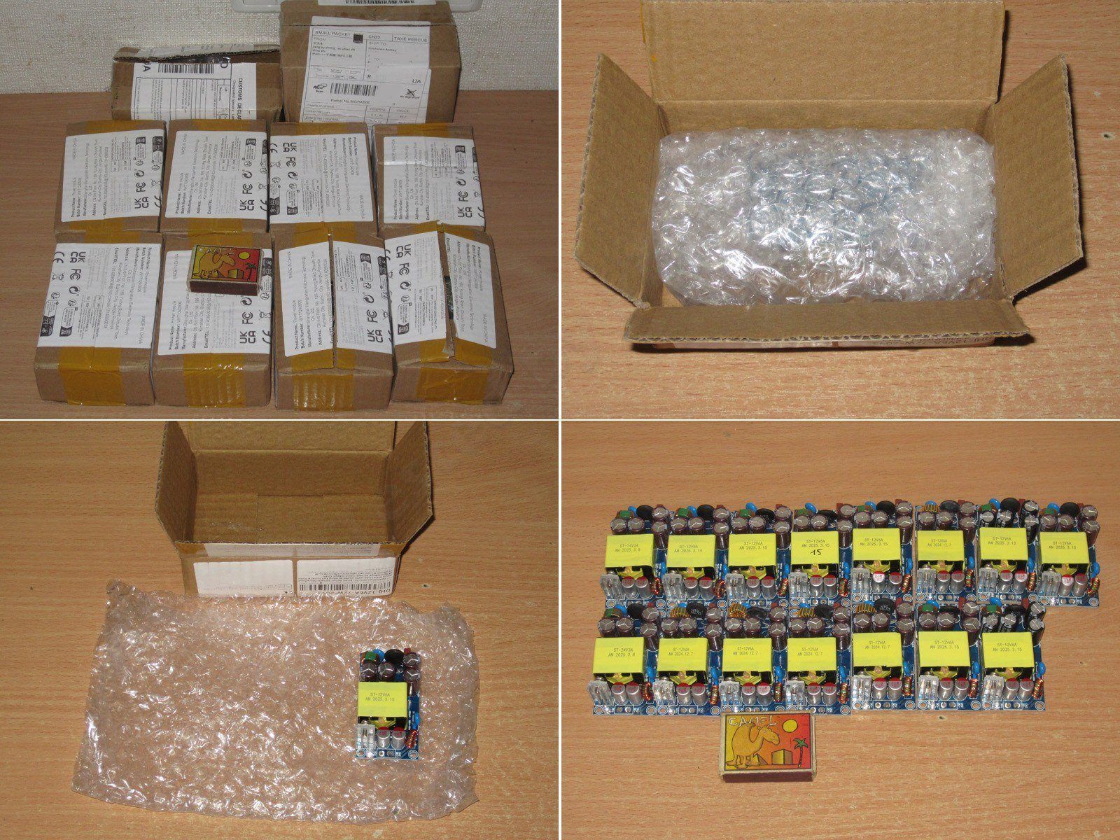
One thing they all have in common is the packaging. Every unit I’ve received, whether bought individually or in packs of 3 or 5, came in a box and was always wrapped in bubble wrap, so it’s very hard to damage them.
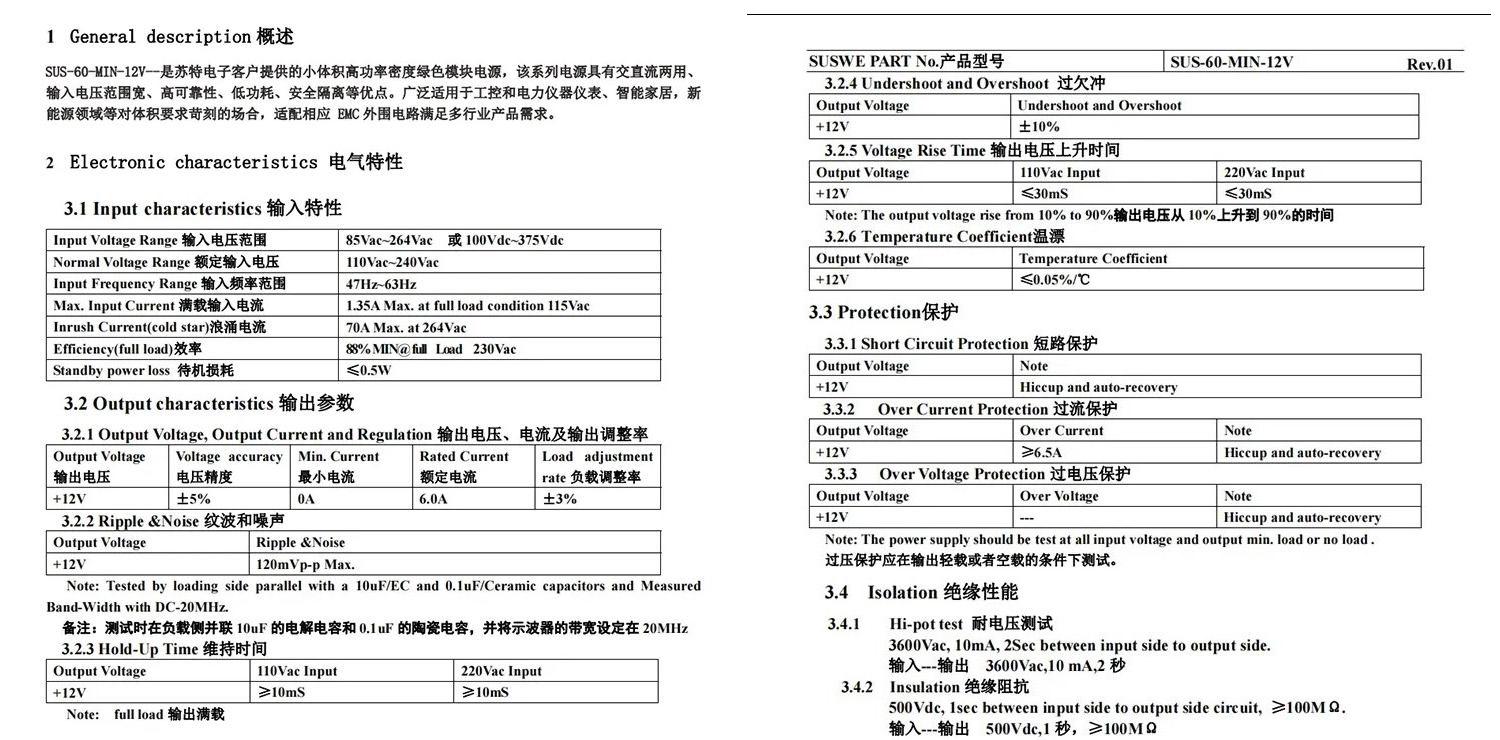
There’s even a datasheet for these power supplies, although it’s only available in fragments and only for the 12 V version. Still, that’s a sign that these are clearly a step above no-name units.
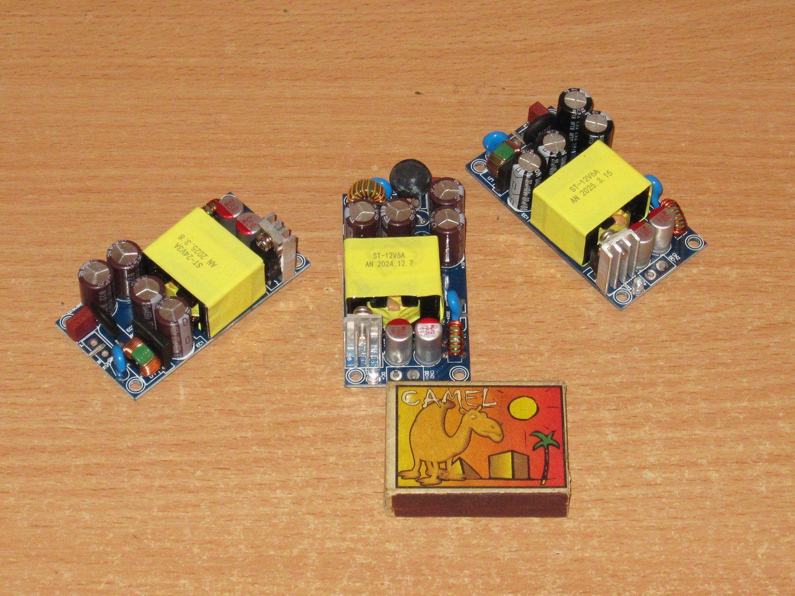
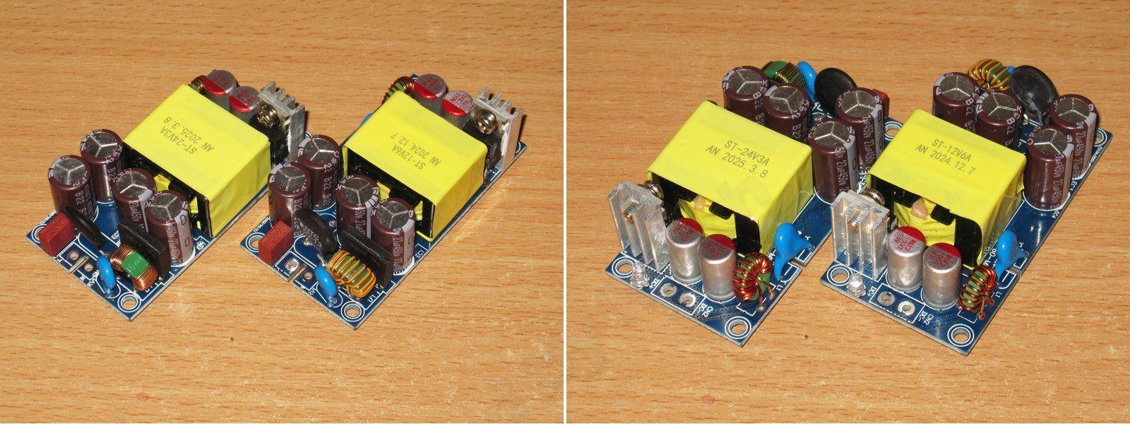
For the demonstration and tests, I picked three units: two 12 V models and one 24 V model. I usually buy the 12 V version, specifically to modify it, but I picked up a couple of 24 V units too. At this power level, they’d work great in a soldering station power supply or some kind of charger.
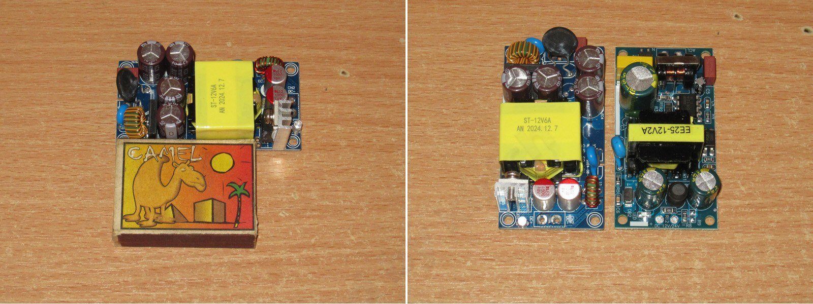
Incidentally, the dimensions match those of the 12 V, 2 A power supply board (in reality, it’s probably closer to 1.5 A) exactly, right down to the spacing between the mounting holes. That means they can replace the original without any modifications to the device. I also use these 12 V, 2 A power supplies extensively, and I have to say their failure rate is very low: I’ve encountered only one failure in a couple of years.
The dimensions in digital form are shown in the picture from the listing.
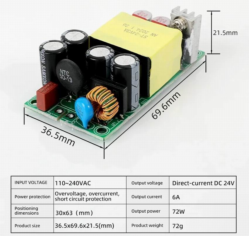
The build is very neat, and the layout is quite compact. You could find things to criticize, but honestly, when you hold one in your hands, it feels like a pretty well-made product.
The store page also has an image showing the components installed on the board. They did leave out the output diode, though, and that’s one of the distinctive features of this power supply model. I’ll explain later.
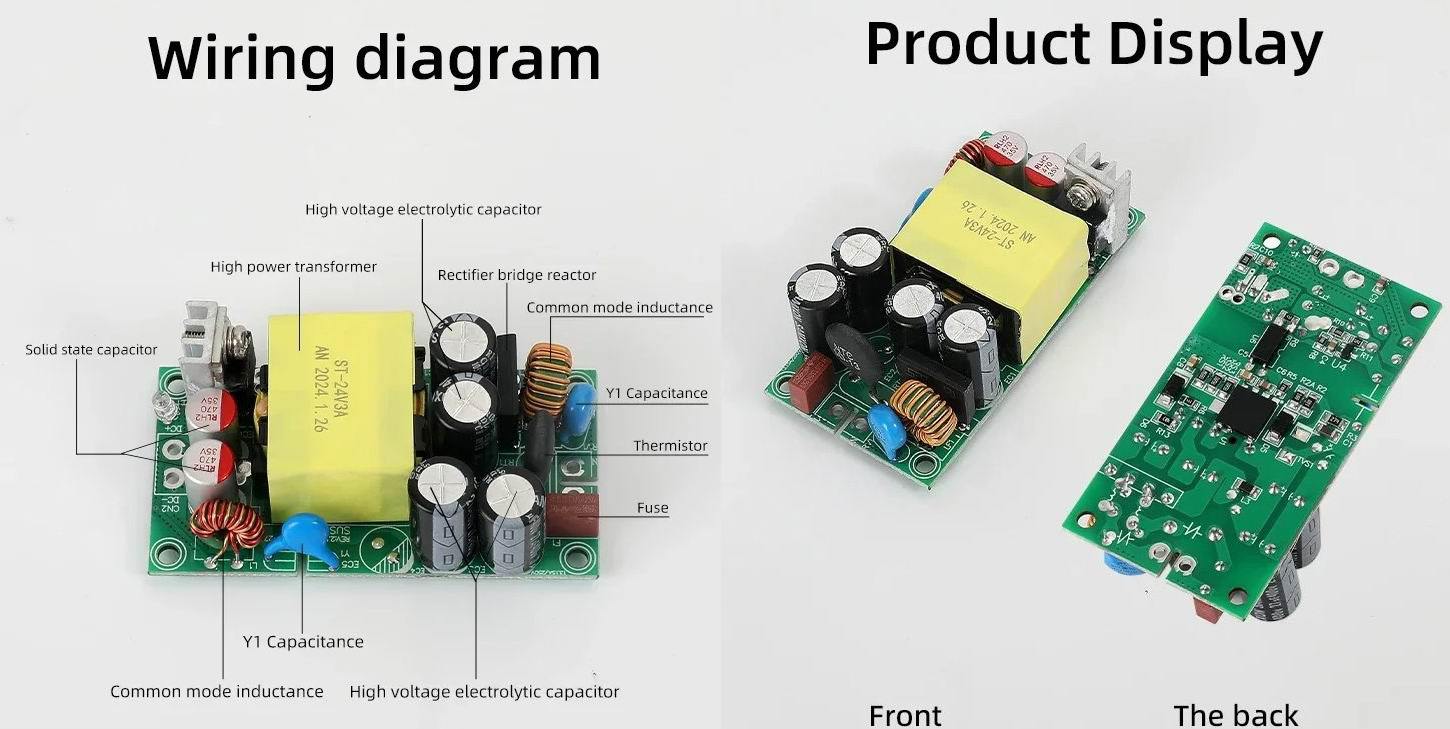
Let’s take a look at the components.
1. On the input side, there’s a fuse, thermistor, varistor, inductor, a fairly large bridge rectifier, and four 27 µF capacitors. Above, I mentioned that I picked two 12 V units for the demonstration. The key difference between them is the capacitors: both are 27 µF, but one unit has 400 V capacitors (black), while the other has 450 V ones (brown).
2. The varistor is rated for a peak voltage of 560 V, so it’s probably there to protect against transient overvoltage.
3. There’s a Y capacitor, with a slot cut into the board underneath it.
4. The output side also has an inductor, a diode, and a pair of polymer capacitors: 470 µF, 35 V in the 24 V version, and 1000 µF, 16 V in the 12 V version.
5. And here’s the feature that wasn’t shown in the image above: the output uses a synchronous rectifier, not just a diode. I didn’t desolder the one in the 24 V version, but the 12 V version has a 10 mΩ model rated for 6 A (the power supply’s stated output current). These rectifiers are used in 5 V, 12 V, 20 V, and 24 V power supplies, and differ in the resistance of the built-in transistor. This version uses a 6 A model. There’s an identical one rated for 5 or 5.5 A; the only difference is that the lower-power one has a fully insulated case. As far as I know, the only higher-rated model is 6.5 A, but either way, this one is excellent.
6. It’s also worth noting that I have at least two revisions of these power supplies, 3 and 4. The differences between them are purely cosmetic.
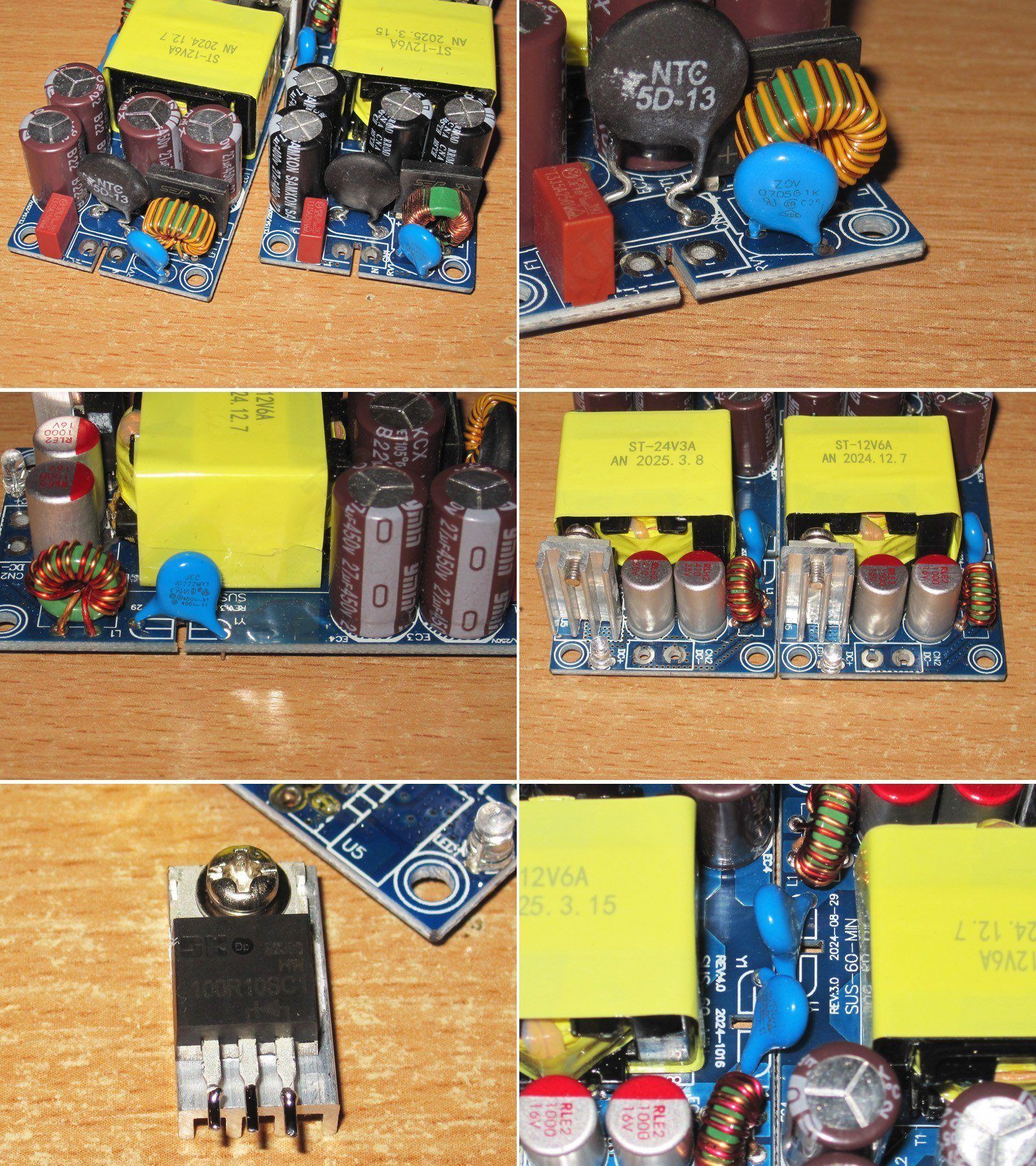
The only difference between the revisions that I noticed is that one has a footprint for an inductor between the high-voltage capacitors, but it’s bridged with a jumper, while the other has no space for an inductor at all.
I also noticed that boards from different sellers vary in whether they have a protective coating. Most of them do, which is another plus. The presence of ceramic capacitors on the output side can also be counted as an advantage.
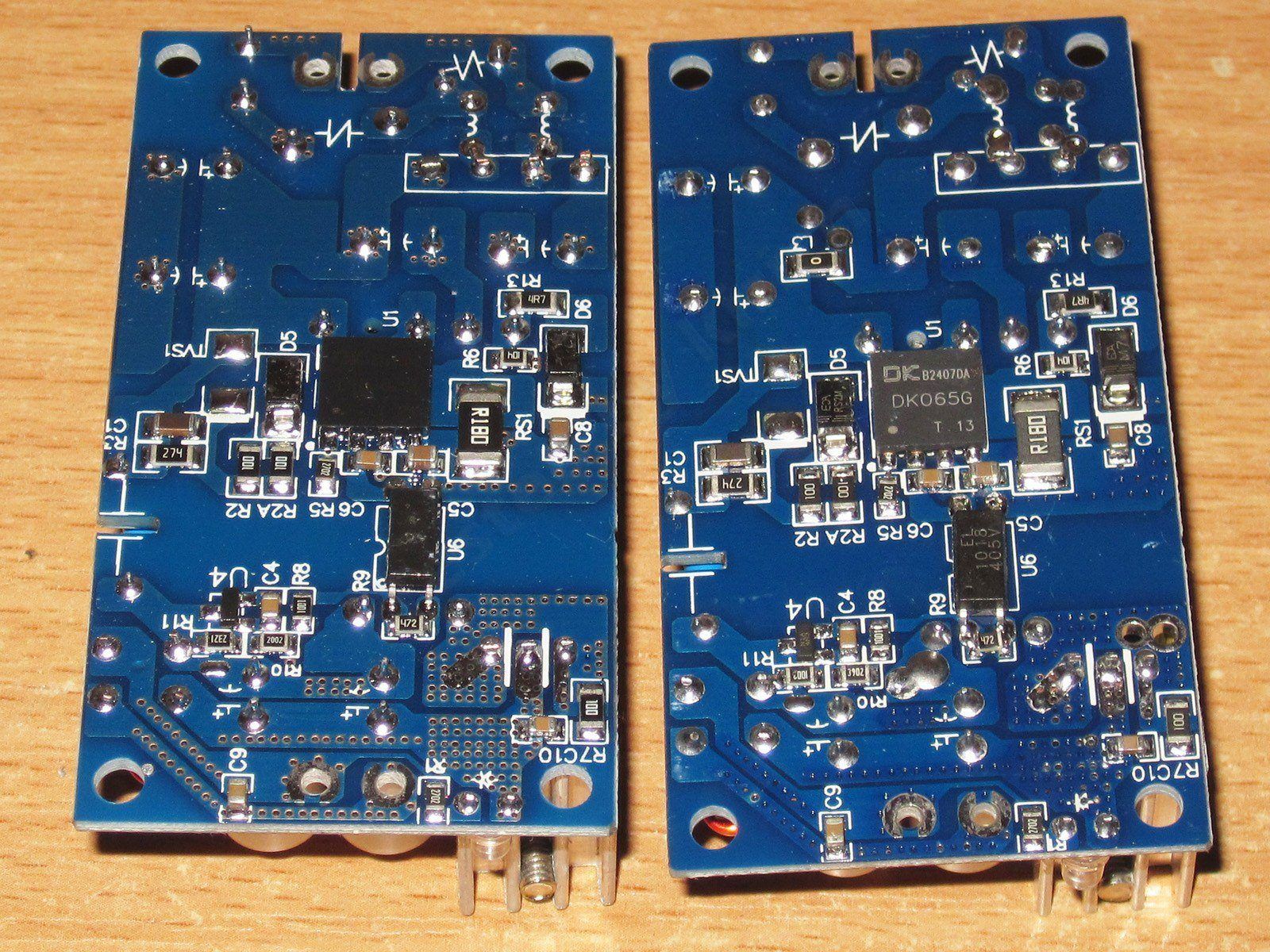
For the demonstration, I used a board without the coating, since it makes things easier to see. And here you can see that the assembly is quite good, as well as the PWM controller chip, the DK065G. This is a PWM controller with a built-in high-voltage transistor and an external current-sense resistor. It's intended for power supplies up to 65 W; there are identical versions for lower power, and it's indeed advertised as a gallium nitride-based chip.
I really like this kind of solution, because it's very hard to mess things up here. The chip already has a full set of protection features, as well as everything needed to control its own high-voltage transistor.
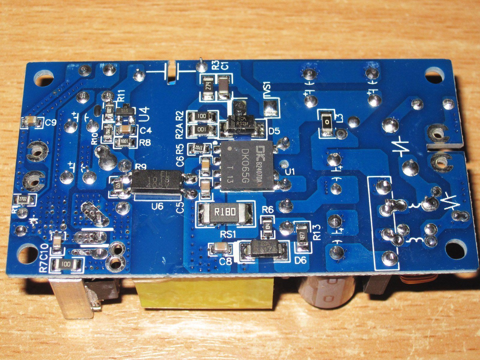
Measuring the capacitance of the input and output capacitors.
1, 2. 12 V with brown capacitors
3, 4. 12 V with black capacitors
5, 6. 24 V with brown capacitors.
You can see that the power supply with the black capacitors has slightly higher capacitance, but for some reason the output capacitors have lower capacitance, even though they have identical markings.
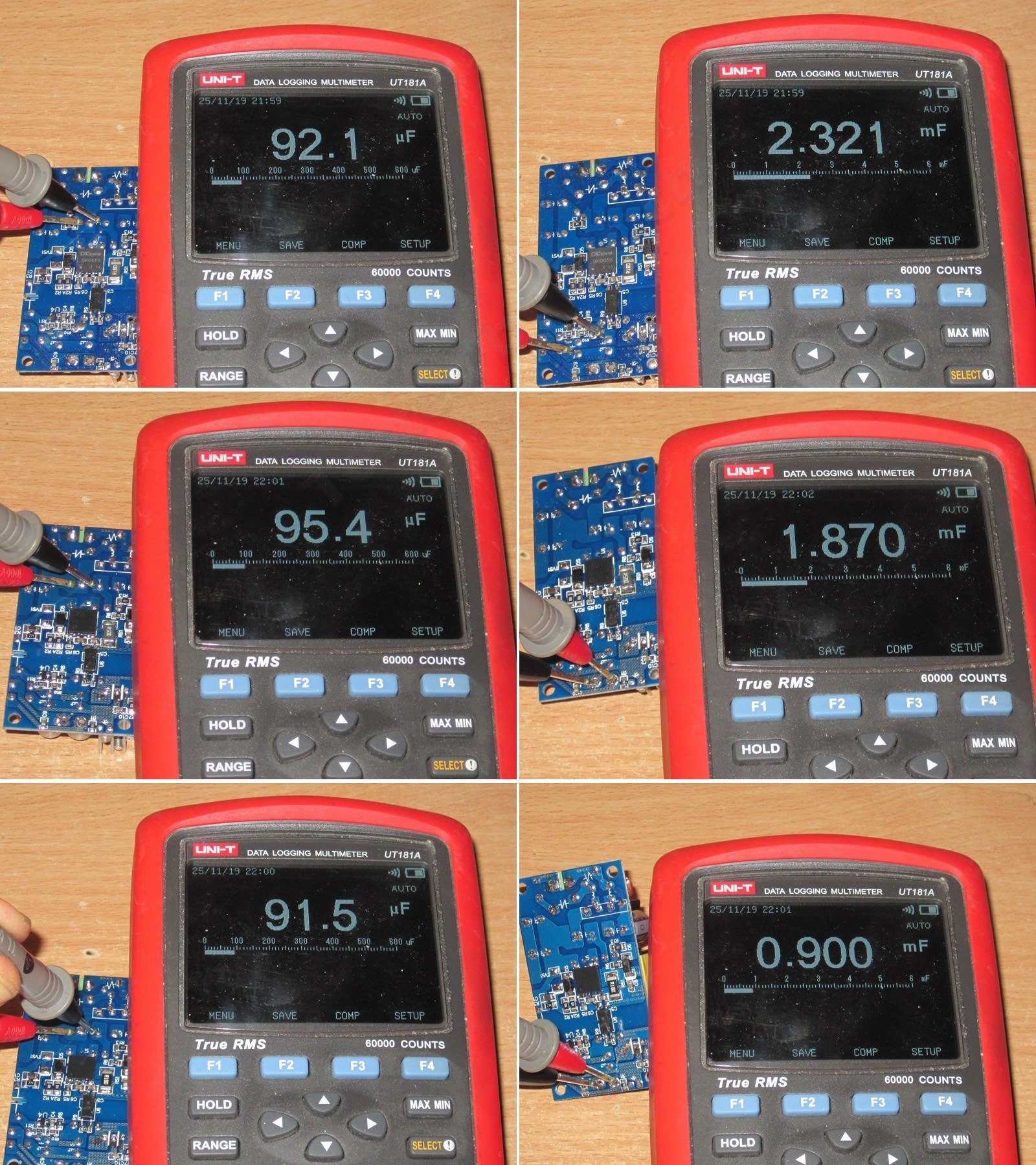
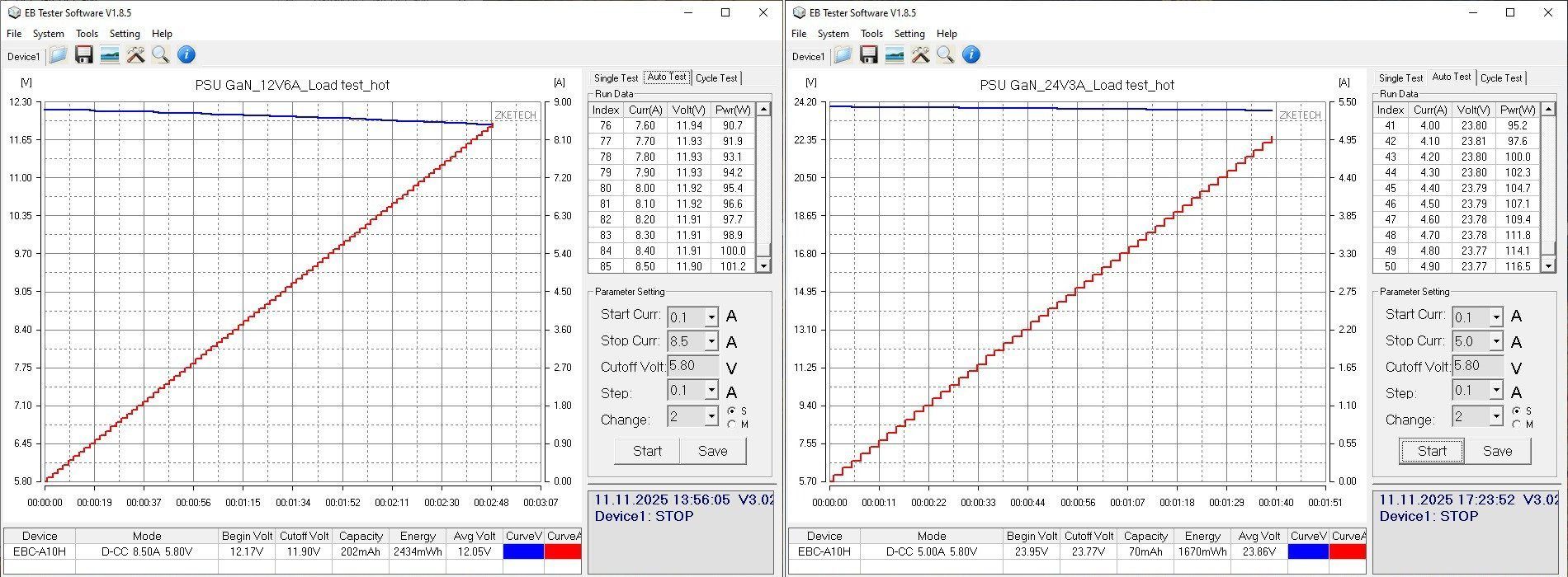
Next, the tests. Since these power supplies are relatively low-power, I used a ZKEtech EBC-A10H load.
And it turned out that things weren't as good as they first seemed. The thing is, I increased the load current on the 12 V units to 8.5–9 A, but the protection didn't trip. On the 24 V version, I increased it to 5 A, and the protection still didn't trip. In other words, with a rated output of 72 W, I was drawing up to 120 W without the protection kicking in. So I stopped the tests there and decided to look into it later.
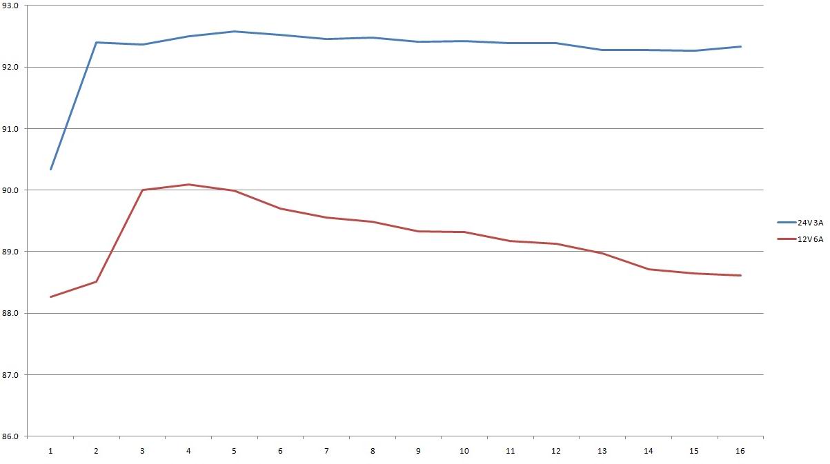
Efficiency measurement results. The datasheet said efficiency is above 88% at full load, and that's true. The 24 V version does even better, at almost 92.5%—excellent for a relatively inexpensive power supply.
For the 12 V power supply, each division on the scale at the bottom is 0.5 A; for the 24 V version, it's 0.25 A. I tested up to 8 A and 4 A, respectively.
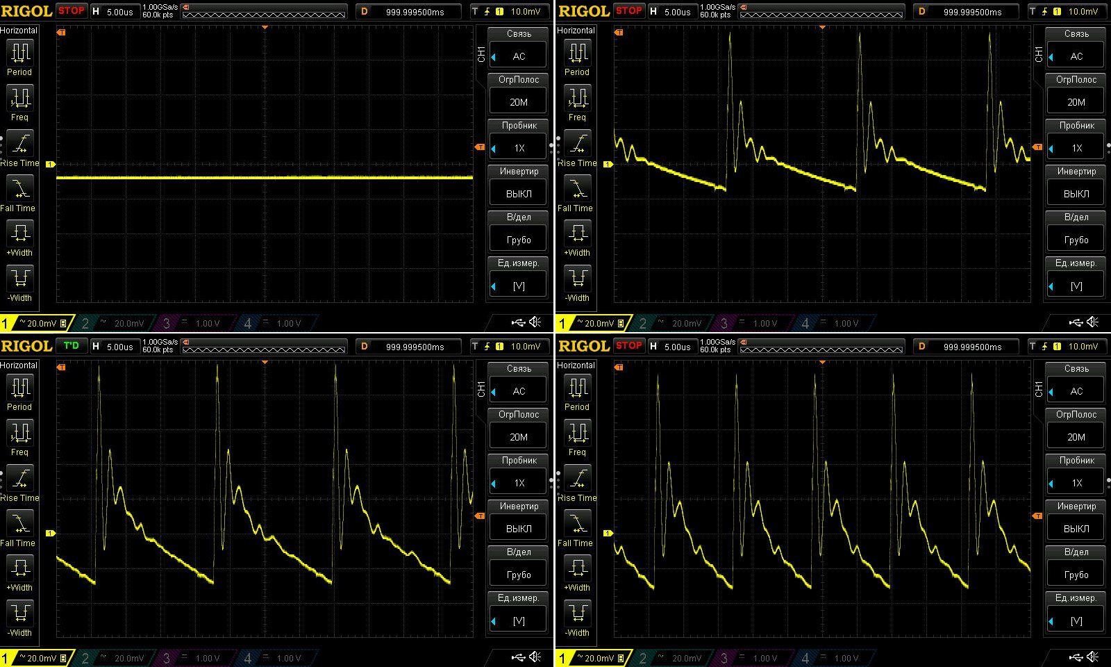
Ripple and tests, starting with the 12 V version.
At no load and at 2, 4, and 6 A, the maximum ripple is up to 120 mV. I wouldn't call that bad, but I somehow expected it to be a bit lower.
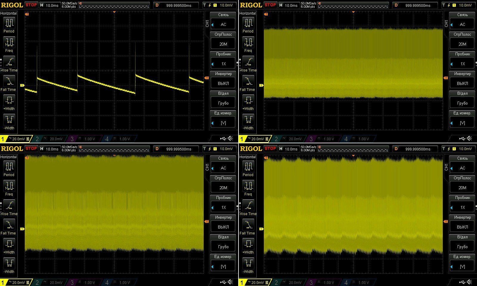
At low frequencies, we see the telltale sign of a “green mode”: 100 Hz ripple starts to become slightly noticeable at maximum current, so overall this is quite normal.
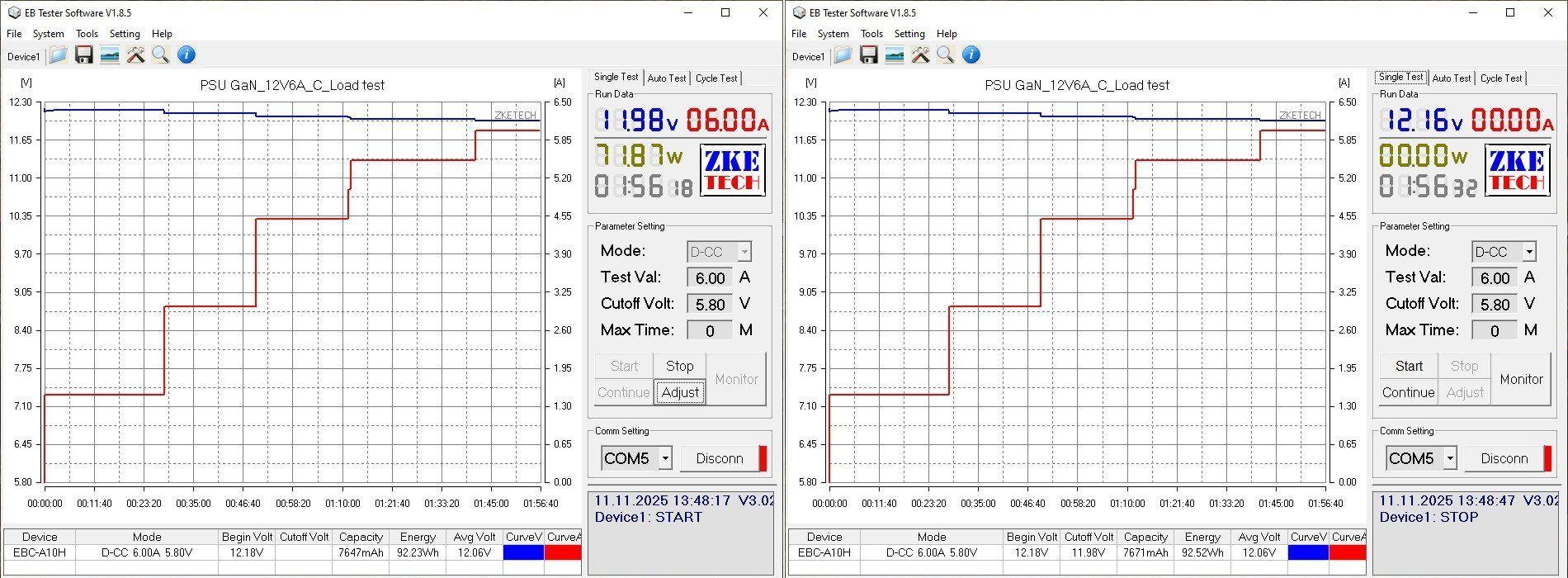
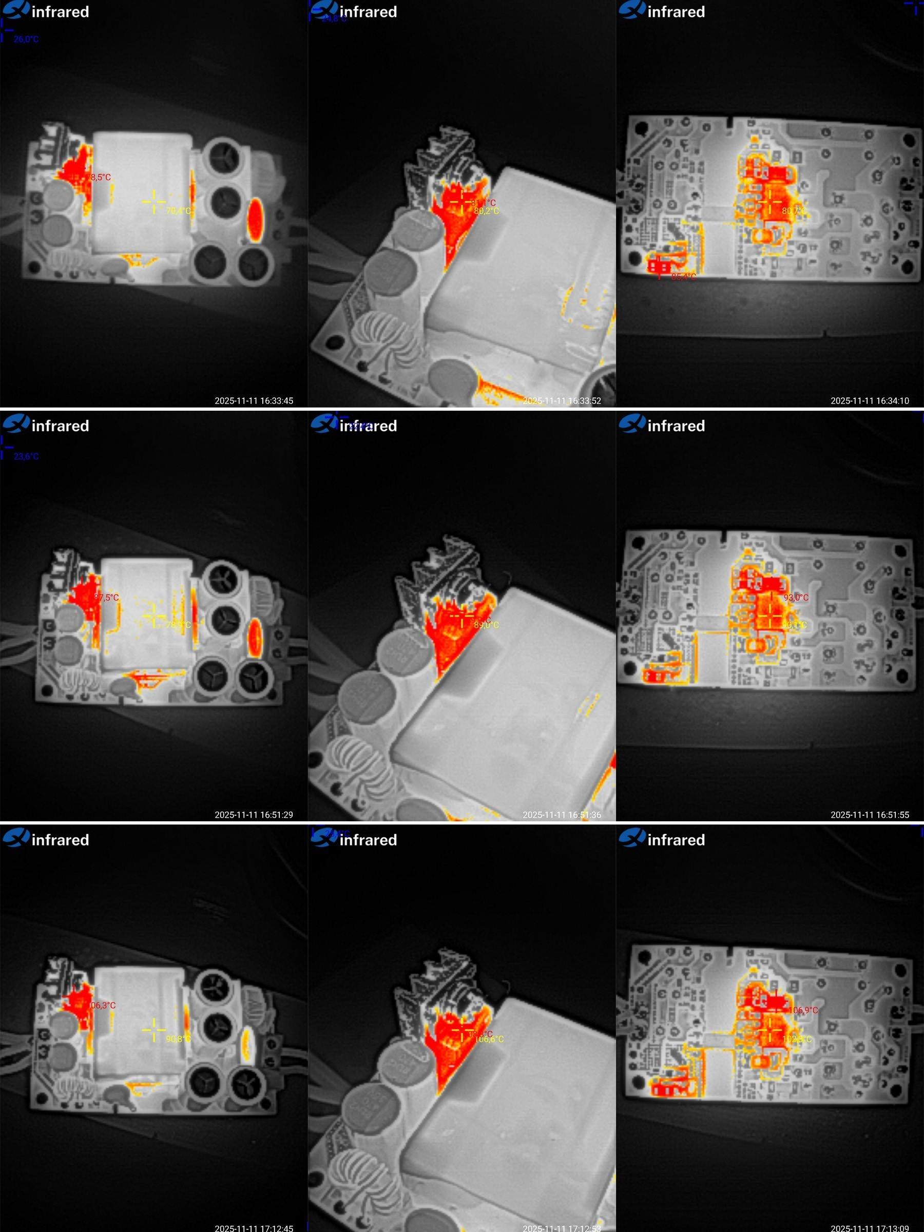
The thermal test had quite a few stages: 1.5, 3, 4.5, 5.5, and 6 A. The total test time was about 2 hours.
The output voltage does vary with load, and by quite a lot—almost 0.2 V. I suspect this is due to the output inductor, which is wound with fairly thin wire. The voltage barely changes with temperature, by about 20 mV.
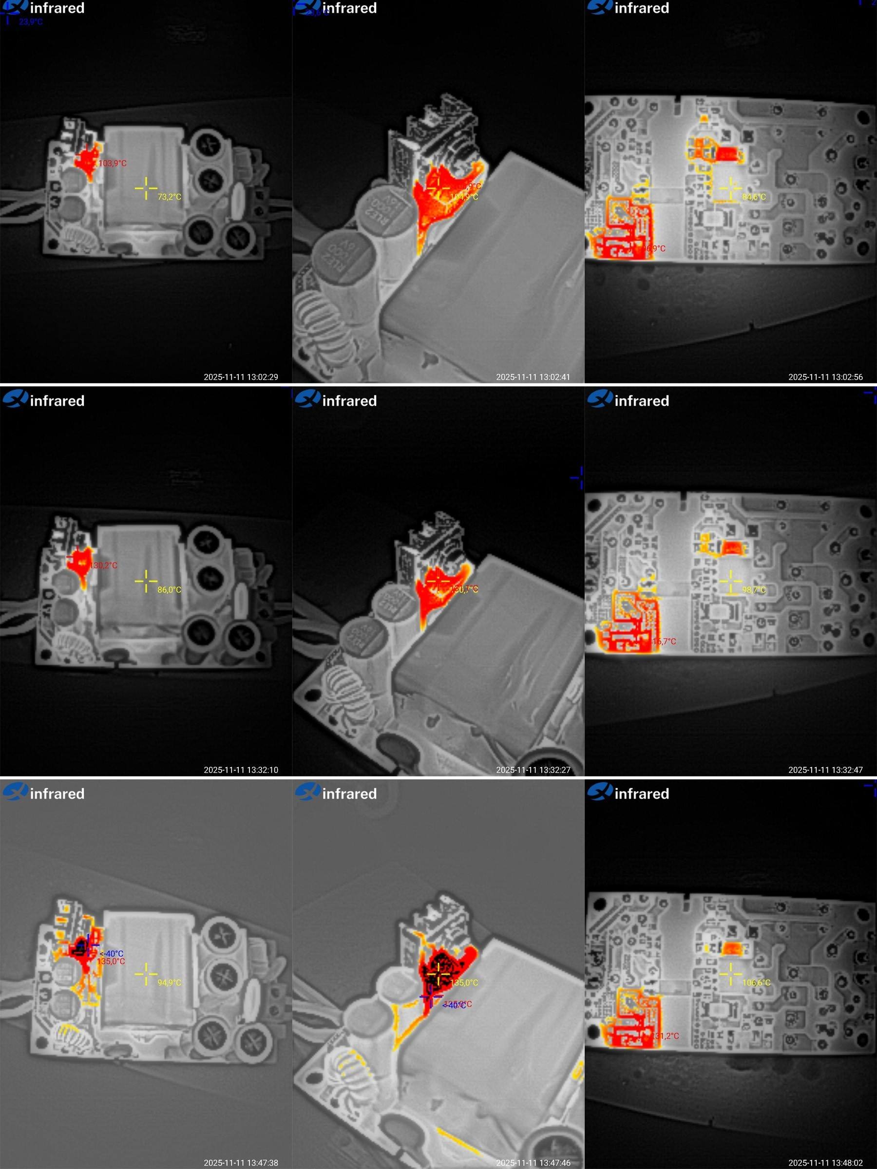
Temperatures at load currents of 4.5, 5.5, and 6 A.
At 4.5 A, there are no complaints: the transformer is at 73°C, the output diode at 104°C, and the PWM controller at 85°C.
At 5.5 A, things are already getting tougher: the transformer is at 86°C, the diode is around 130°C, and the PWM controller is at 99°C.
At 6 A, there are signs of overheating: the transformer is at 95°C, which is fine; the diode is above 135°C (the thermal camera is off the scale), and the PWM controller is at 107°C, which is rather high.
So I can say that the actual continuous output current without overheating is around 4.5 A. But with even a little airflow, the power supply should handle not just 6 A, but probably more. The situation could also be improved by increasing the size of the output diode's heatsink.
Now for the 24 V power supply.
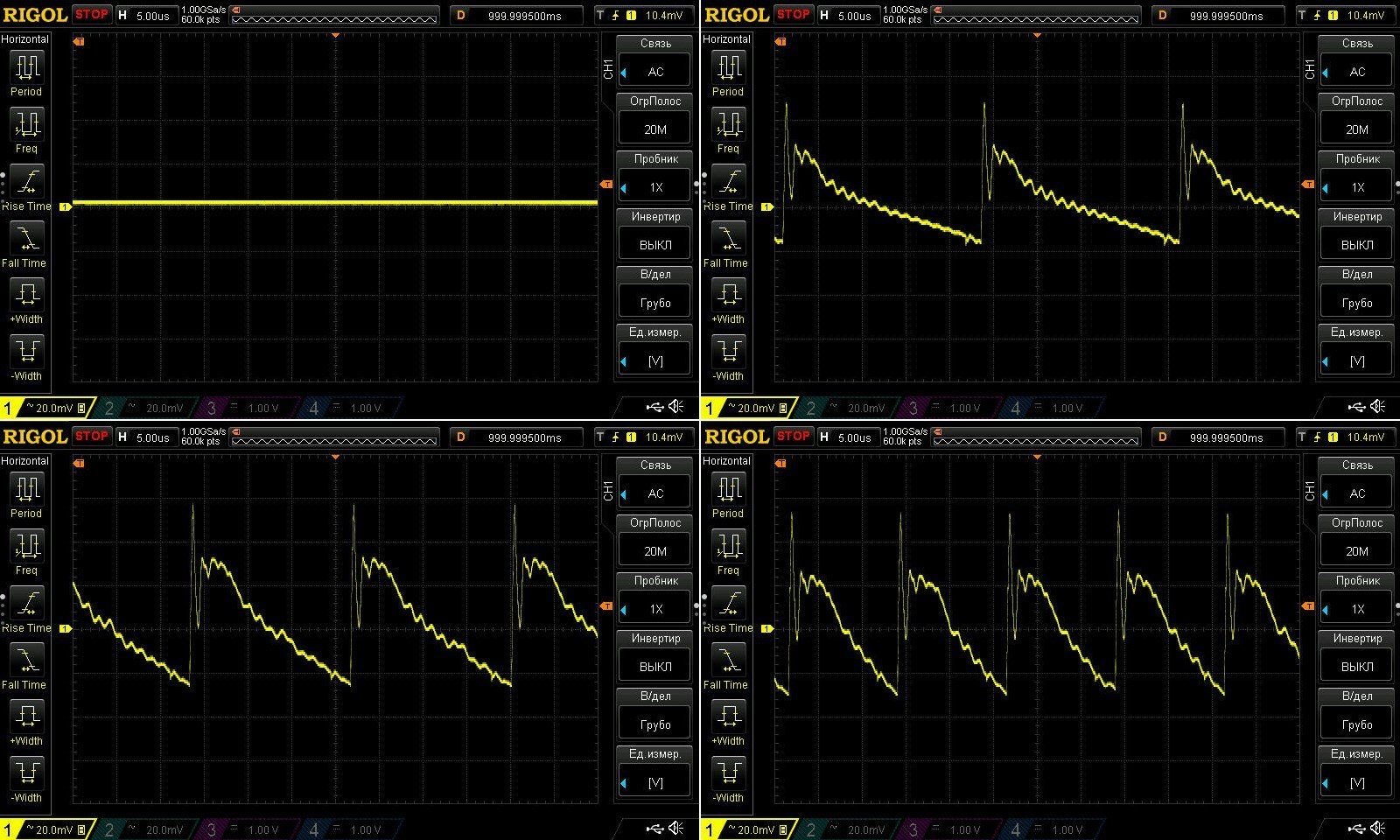
And, surprisingly, the ripple is lower here, although usually it's the other way around.
I measured it at no load and at 1, 2, and 3 A.
Even at maximum current, the peak-to-peak ripple is about 80 mV, one and a half times lower than on the 12 V version. As a percentage, the difference is even greater.
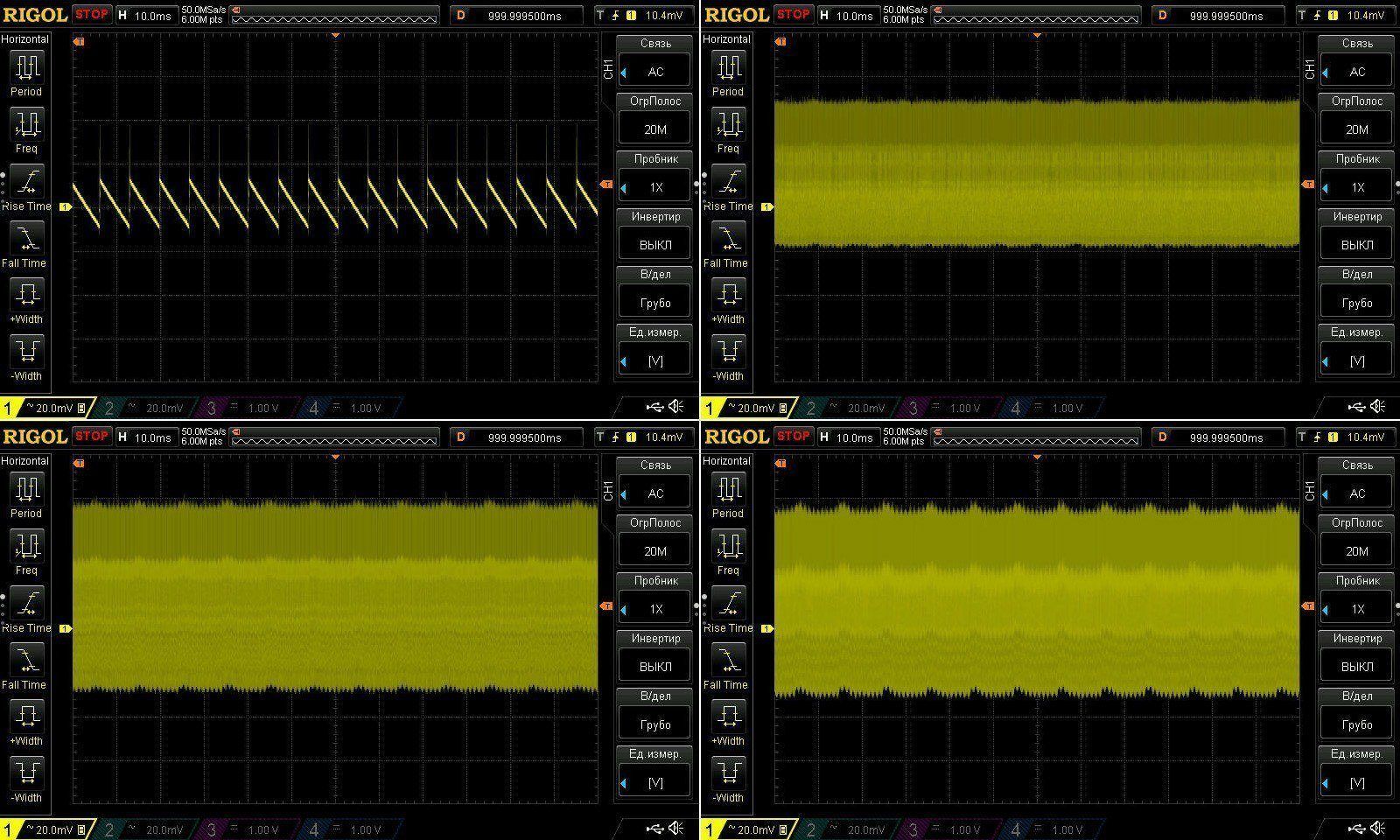
The low-frequency picture is similar to that of the 12 V version, but the overall ripple is of course lower, simply because the high-frequency ripple is lower.
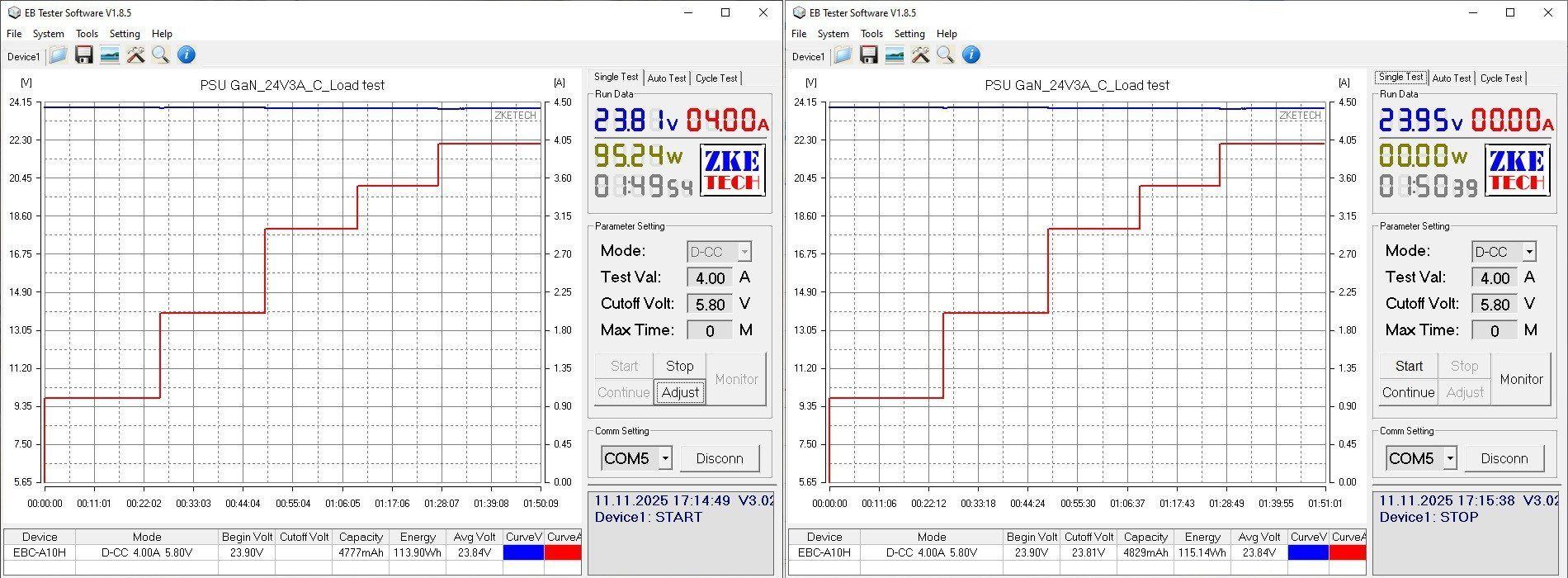
The thermal test was more interesting here. I first loaded it at 1, 2, and 3 A, but the power supply performed perfectly, so I also tested it at 3.5 A and then at 4 A.
In other words, I actually finished the test with the output power just under 100 W.
The output voltage varies slightly less with load, around 140 mV. The absolute temperature-related variation is greater than on the 12 V version, at about 50 mV, but the relative variation is roughly the same.
Temperatures at currents of 3, 3.5, and 4 A.
At 3 A: transformer 70 degrees, diode 80, PWM controller 81 degrees. Everything looks good.
At 3.5 A: transformer 79, diode 90, and PWM controller 90 degrees. Still excellent.
At 4 A: transformer 91, diode 107, PWM controller 103 degrees.
In fact, this power supply can run continuously at 4 A without any particular problems, even though it's rated for 3 A. The higher efficiency of this model is a factor here. In my opinion, it's simply excellent.
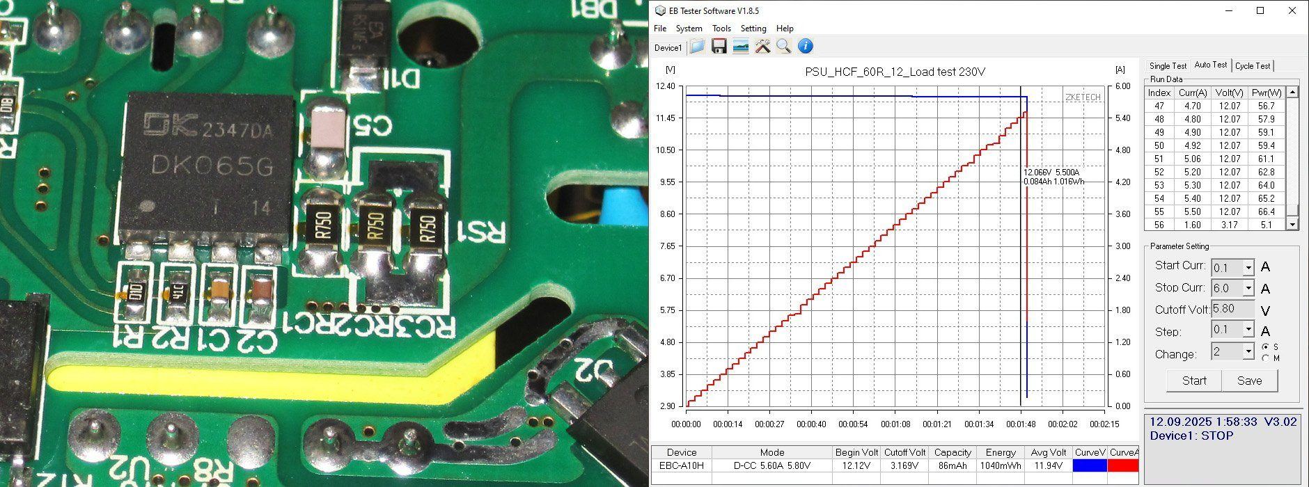
I was done with the main tests, but the protection current was still bothering me: I hadn't managed to push the units to the point where the protection kicked in.
Interestingly, I'd reviewed a power supply using the same chip before. Its shunts had a combined resistance of 0.25 Ω, but the protection current was around 5.5 A. This one has 0.18 Ω shunts, yet it kept running even at 8.5 A.
So, scaling the shunt value, the protection should have tripped at 0.25/0.18 = 1.39 times the current. 5.5 A × 1.39 = 7.65 A, which is clearly less than 8.5 A.
I even wondered if there was a PCB layout mistake and the shunt wasn't actually in the circuit, but no, I checked and everything is correct.
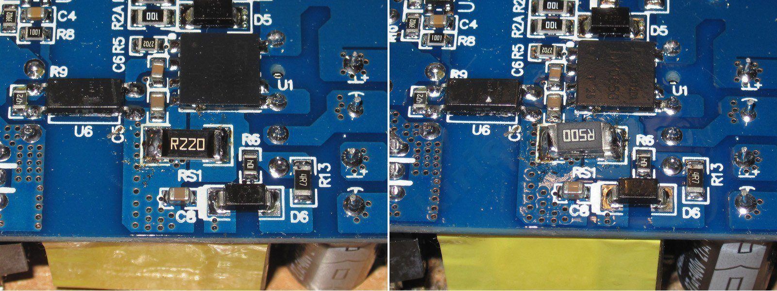
I replaced the shunt with a 0.22 Ω one, but wasn't happy with the result. I wanted to try 0.25 Ω next, but didn't have one, so I put two 0.5 Ω resistors in parallel.
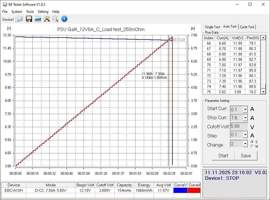
With the 0.25 Ω shunt, the protection tripped at around 7.3–7.4 A. Honestly, this is very strange: two units, using the same chip and the same shunt value, but one trips at 5.5 A and the other at 7.3 A. The only thing I can think of that might affect this is the transformer's winding specifications, but that's just a guess.
In any case, I can say two things:
1. The protection is there and works, but in practice the trip current for the 12 V version is around 10 A. I didn't test the 24 V version, but I think the current will change proportionally.
2. It's better to replace the shunt with a 0.25 Ω one; then the protection will work more reliably.
Conclusions.
In my opinion, this is a strong contender for the title of “people's power supply.” Quality assembly, good components, a well-designed circuit, an input filter and varistor, a GaN-based PWM controller, decent capacitor capacity, a relatively large transformer, polymer capacitors on the output, synchronous rectification, even a conformal coating on the board. It's a little gem of a power supply, especially at such a low price.
This power supply costs around 7 dollars, and during sales, with a coupon, you can realistically get several for about 5–5.5 dollars each.
Two things spoil the picture, maybe even three:
1. The 12 V version gets quite hot; it won't deliver 6 A continuously without airflow.
2. Ripple is also somewhat higher on the 12 V version. Still, given that it's only 1% peak-to-peak, that's perfectly normal and even pretty good. What's more surprising is that it's noticeably lower on the 24 V version.
3. The shunt resistor is clearly undersized here. The original is 180 mΩ; I recommend replacing it with a 250 mΩ one. And yes, the board uses a 2 W resistor, so use either a pair of 500 mΩ, 1 W resistors stacked one on top of the other, or a single 250 mΩ, 2 W resistor (if you can find one).
That's all for now. I liked these units; I'm especially impressed with the 24 V version, and the 12 V one isn't much worse. Overall, I recommend them.
As usual, I'd be glad to hear your comments and feedback if you decide to buy one for yourself.
https://www.kirich.blog/obzory/bloki-pitaniya/1291-bloki-pitaniya-12-i-24-volta-72-vatta-kompaktnye-moschnye-nedorogie, компактные блоки питания для 24волта обзор
Questions and answers
What efficiency did the 12 V and 24 V, 72 W power supplies achieve?
The 24 V version reached nearly 92.5% in testing. The datasheet states efficiency above 88% at full load.
At what current does the 12 V power supply’s protection trip?
It trips at about 10 A, although the rated power is 72 W. The author recommends replacing the stock 180 mOhm shunt with a 250 mOhm one.
Can the 12 V power supply run at 6 A continuously?
The author says the 12 V version will not sustain 6 A without airflow because it gets quite hot.
This model is included in the summary table: Comparison of power supplies: ripple, efficiency, and temperature rise
The figures from this review are in the measurement database: Power supplies
Discounted products
You may be interested in



Discounted products
All the content on the site and the advice are free, but we’d be grateful for your support of the project and the channel!
Comments5
Only registered readers can comment. It takes a minute to sign up, and you can log in with the same account you use on the forum.
Log inRegister
Comments are published in their original language.