
A new converter model from Riden, RK6012
A reminder: to keep up with new posts on the blog, I recommend following me on Instagram. I’ll post notifications about new articles there, and might also write about something interesting from time to time - link to my account
You can also subscribe to updates and new articles on the Telegram channel - https://t.me/KirichBlog Just a note: discussion of reviews and articles is enabled on the channel, as is general chat. I recommend it.
I’ve already reviewed the previous version, so this one will be relatively short, since some of its features are essentially the same as those of the previous model.
But I’ll start the review by listing all the products from this company that I’ve tested.
DPH5005
DPS8005
DPS5020
RD6006
RD6012
RD6018
RD6006P
RD6012P
RD6024
RK6006
Enclosure and power supply for the RK6006
RD6030
Silicone case covers
RD 25A cable set
RS485 module with galvanic isolation for connecting RD60xx series converters
RD6018P
RD6012H
This model is the logical next step in the RK60xx lineup, though it turns out to be quite a bit more interesting.
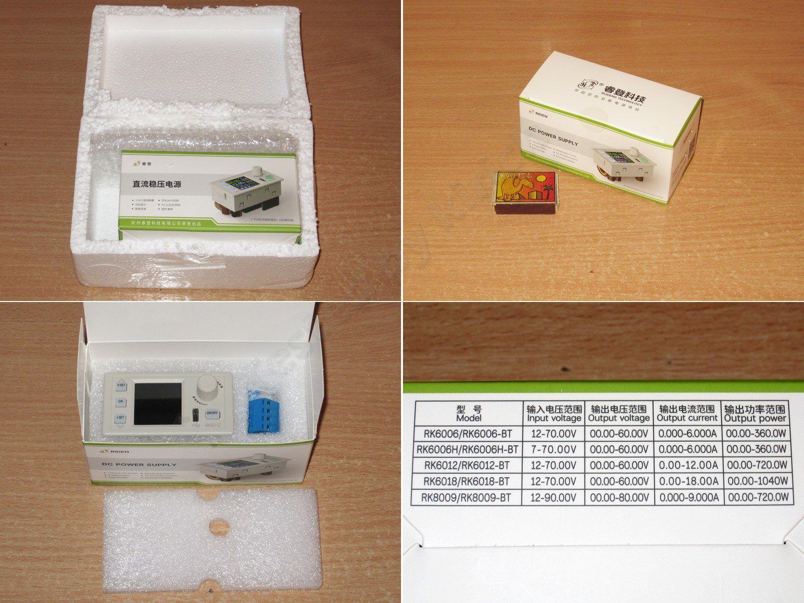
The packaging is standard for this manufacturer, although this time I found that the foam box had been glued shut. At least, I couldn’t open it neatly. The contents are all typical. Nothing new.
But when I turned the box over, I spotted a very interesting table. Alongside the previous 6006 model and the new 6012, it lists three more versions that we can probably expect in the future.
First, they plan to release an even more powerful version, the 6018, rated for 60 V and 18 A.
There’s also a version with an H suffix, which is along the lines of the 6012H, i.e. with a universal power supply.
And there will also be a replacement for the old but very interesting 8005 model: the 8009, rated for 80 V and 9 A.
Honestly, I like this. I also like that they keep making their products for a long time, unlike Atorch, which just discontinued theirs....
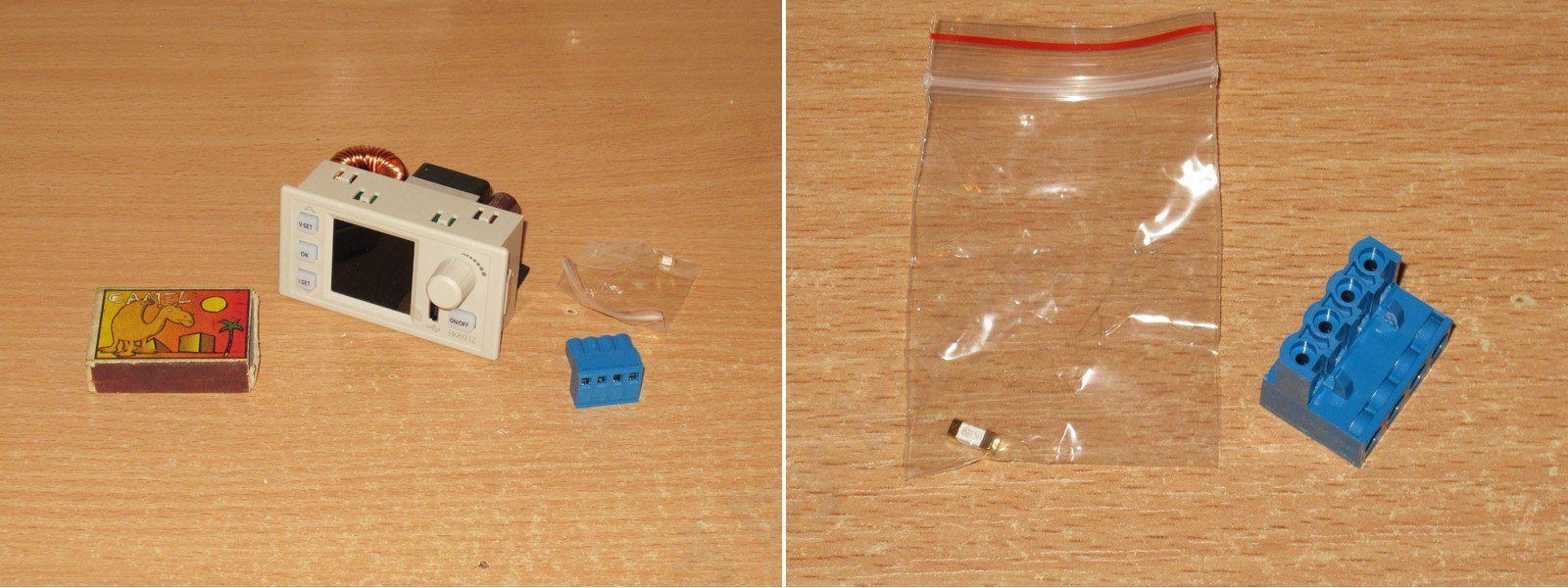
I ordered the basic version. The package includes only the converter itself, a terminal block in an unusual blue color, and a 15 A fuse.
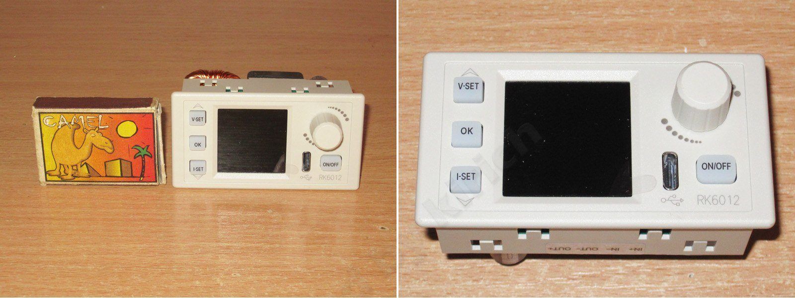
The converter is very compact, and the front panel is identical to that of the previous RK6006, so you could essentially just replace your old one with this more powerful model. Actually, there is one difference: the old version had MicroUSB, while this one has USB-C.
The store link at the beginning and end of the review also offers an assembled version in an enclosure with a power supply. Unfortunately, its power supply has the same power rating as the one for the 6006, so you can certainly draw 12 A, but only up to 30 V; above that, you’ll have to reduce the current.
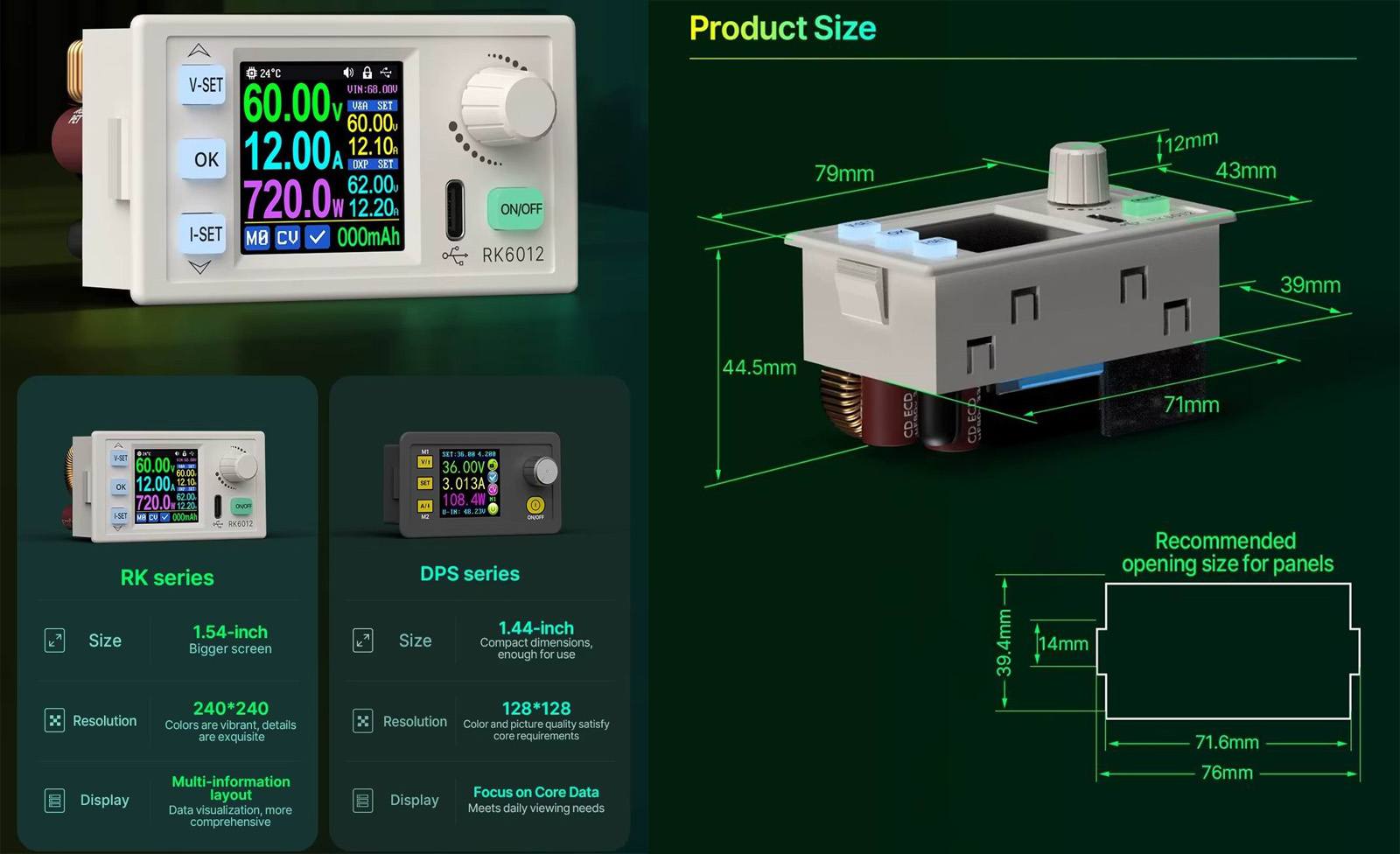
These converters are positioned as replacements for the outdated DPS series. As far as I remember, the most powerful model in that series was the 6005; anything more powerful already had an external power board.
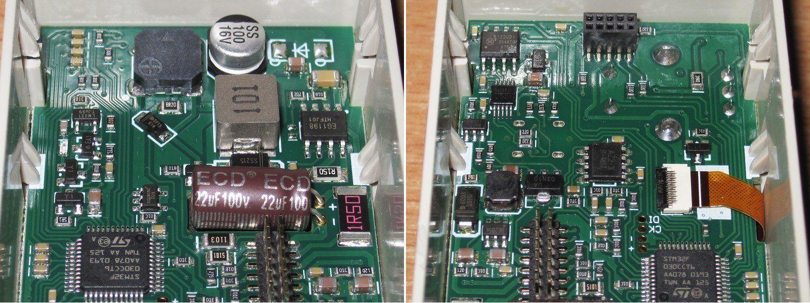
The layout is very compact. The control board is even on a separate submodule. There’s also a very small fan, which, by the way, runs relatively quietly. It turns on when the temperature exceeds 55 degrees or the current goes above 6 A.
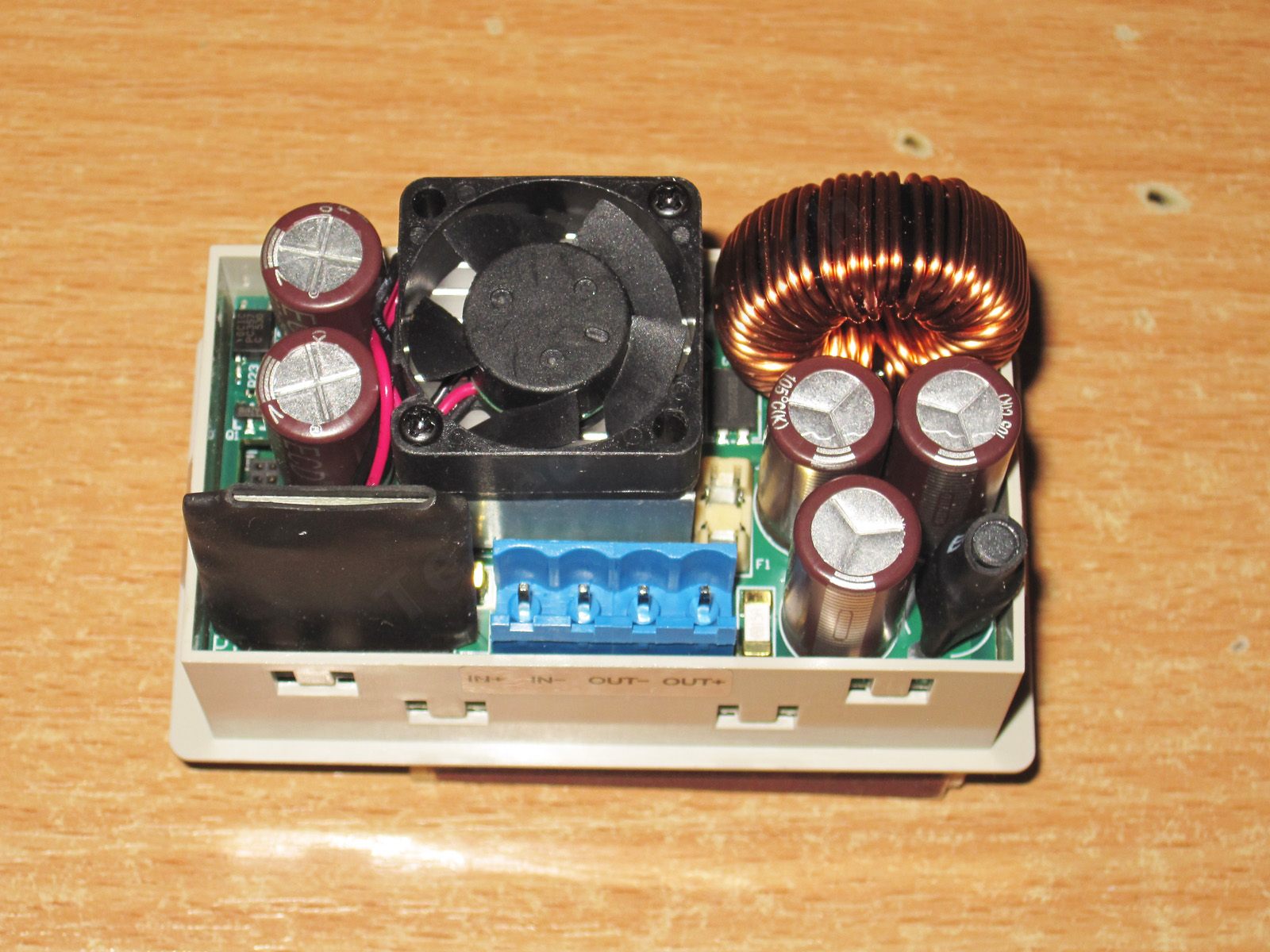
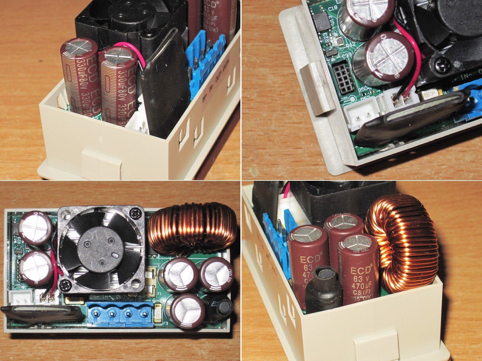
At the input there are two 330 µF, 80 V capacitors. Next to them are connectors for the Bluetooth module and an external temperature sensor.
The fuses are soldered to the board. There’s a small panel next to the output fuse. The output capacitors are rated at 63 V and 470 µF, and here I have to point out that the voltage rating is a very tight fit. Two inductors are visible nearby: a large energy-storage inductor and a smaller one for filtering ripple.
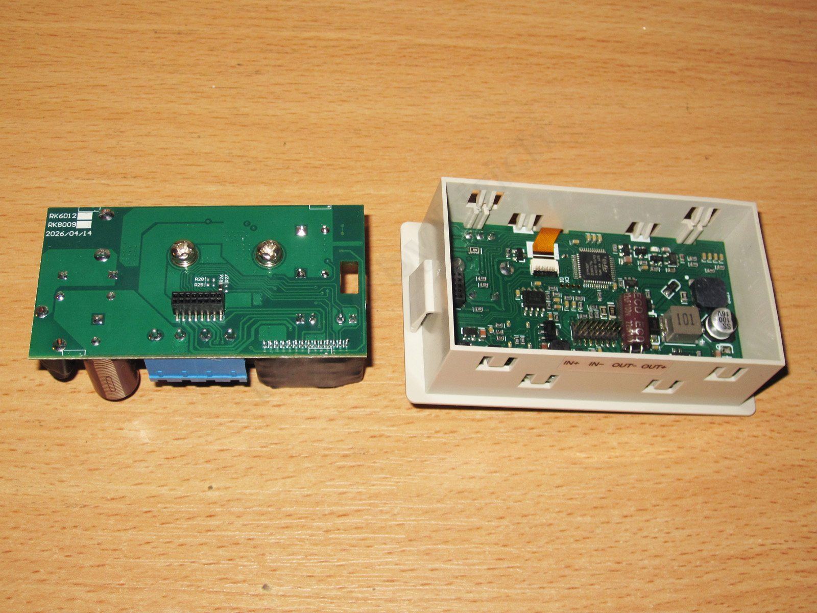
The board comes out fairly easily, but there’s basically nothing interesting on its underside. The other board has plenty going on, though: the microcontroller, auxiliary power supply, and so on.
All the controls are on the lower board. The layout is moderately dense, and the assembly is neat.
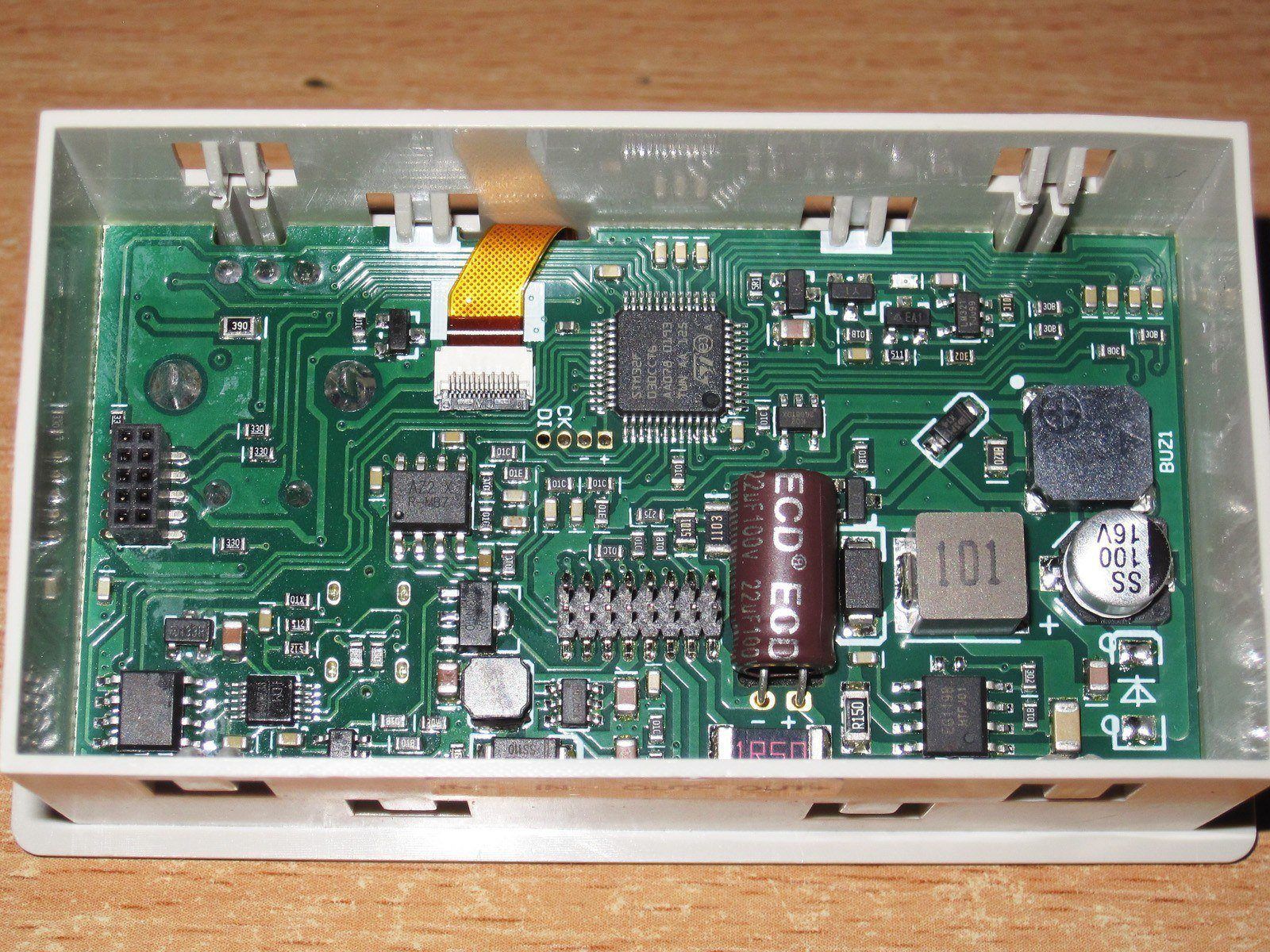
1. Microcontroller, power supply, buzzer.
2. Another small DC-DC converter, probably powering the control circuitry. A USB chip is visible nearby; as far as I can tell, the port is galvanically isolated.
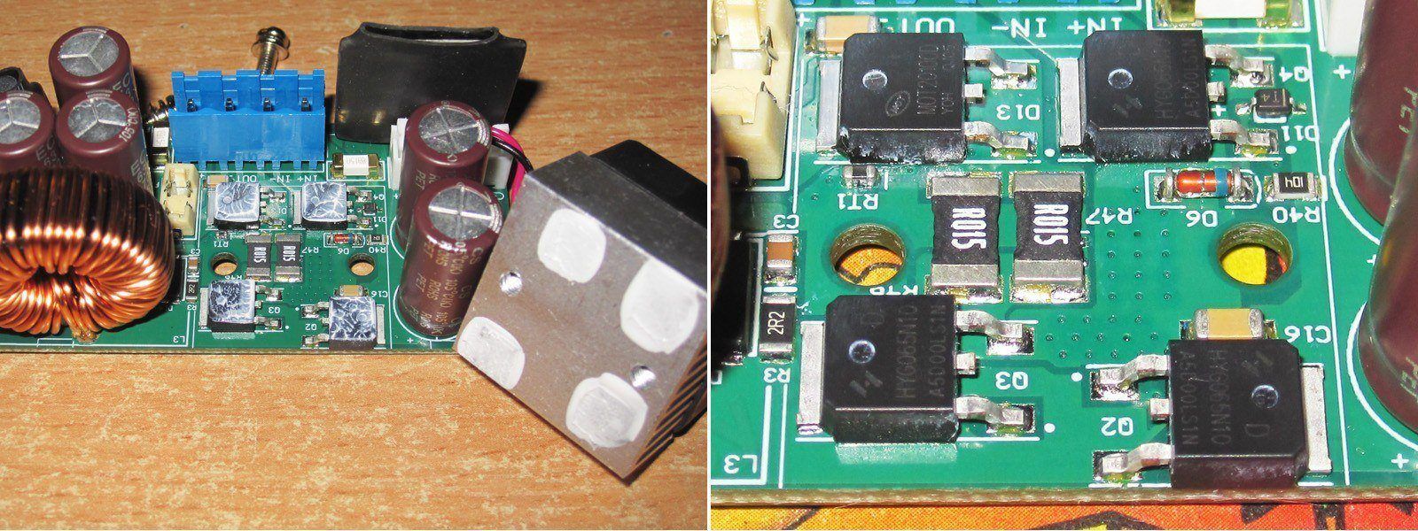
Naturally, I removed the heatsink. There’s thermal paste, but the heatsink is basically only pressed against the transistor cases. On the plus side, its fins are oriented to also direct airflow over the power inductor.
Under the heatsink are a 20 A, 100 V diode assembly and three HYG065N10 transistors. As I understand it, they’re rated at 100 V/93 A/6.8 mΩ. I’d guess one is for reverse-polarity protection and the other two form a synchronous DC-DC converter, but I’m not certain.
Let’s not keep you waiting—time to switch it on.
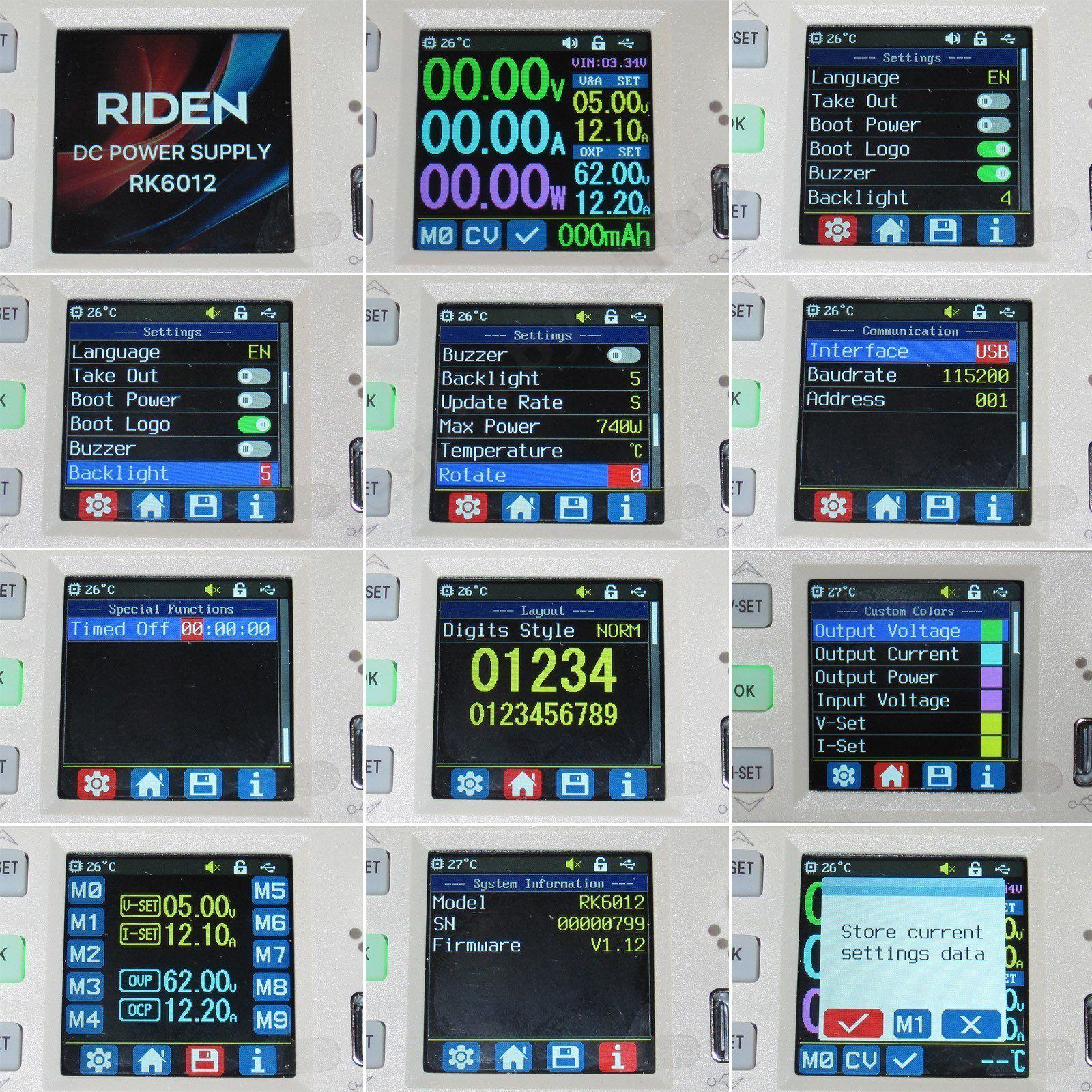
After that, it’s the usual: startup screen, then the main screen.
The menu is also pretty typical, though there’s a new option for the auto-shutdown time. Nice.
A long press of the OK button on the main screen opens the menu for working with preset memory.
If you noticed, there’s an output power setting. If you’re replacing a 6006 model in the old case, be sure to set it to the appropriate value of 360–370 W. The converter will then limit the current automatically when the output voltage is above 30 V.
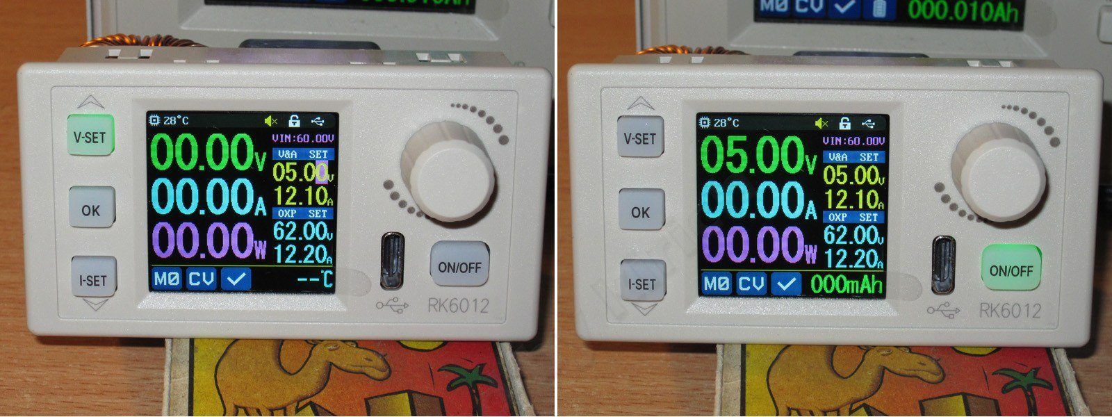
The keypad is excellent: soft, with great tactile feedback and a subtle backlight for the active button. They really got this part right.
One thing I didn’t like right away was how the adjustment step size is selected. Pressing the V-set or I-set button puts you in voltage or current setting mode, starting at the smallest step. But pressing the encoder doesn’t move from the smallest step to the next one; it jumps straight to the largest. For voltage, that means whole volts; for current, tens of amps. This kept throwing me off, since I’m used to stepping up through the options, not down.
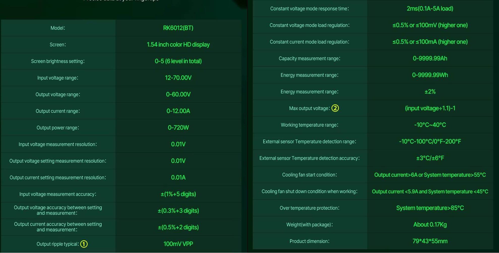
The description—or, more precisely, the specifications—comes with a couple of footnotes. More on those later.
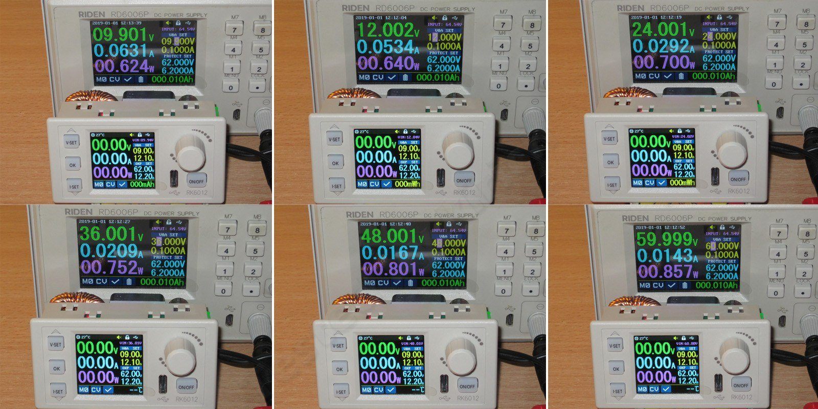
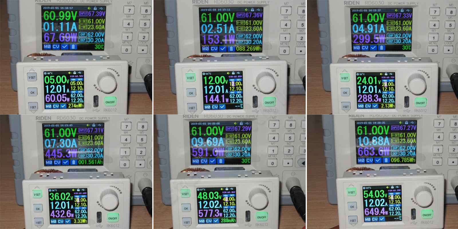
First, I checked its own power consumption.
1. It starts up at around 9.9 V and shuts down closer to 9 V.
2–6. Power consumption with input voltages of 12, 24, 36, 48, and 60 V.
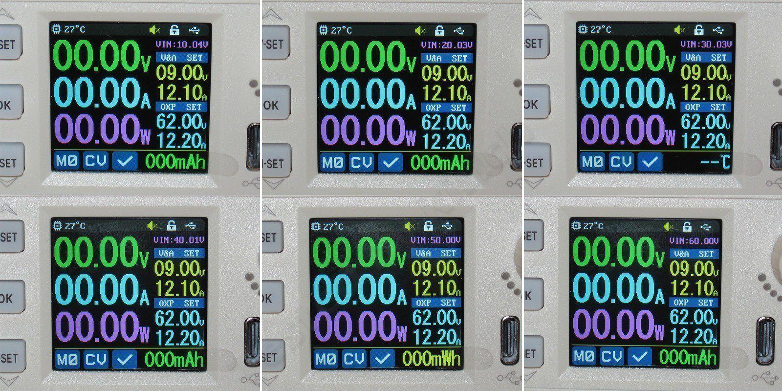
Next, the tests. First up is checking the accuracy of the input voltage measurement—the small voltmeter in the upper-right corner.
I checked it at 10, 20, 30, 40, 50, and 60 V, and I have no complaints about its accuracy.
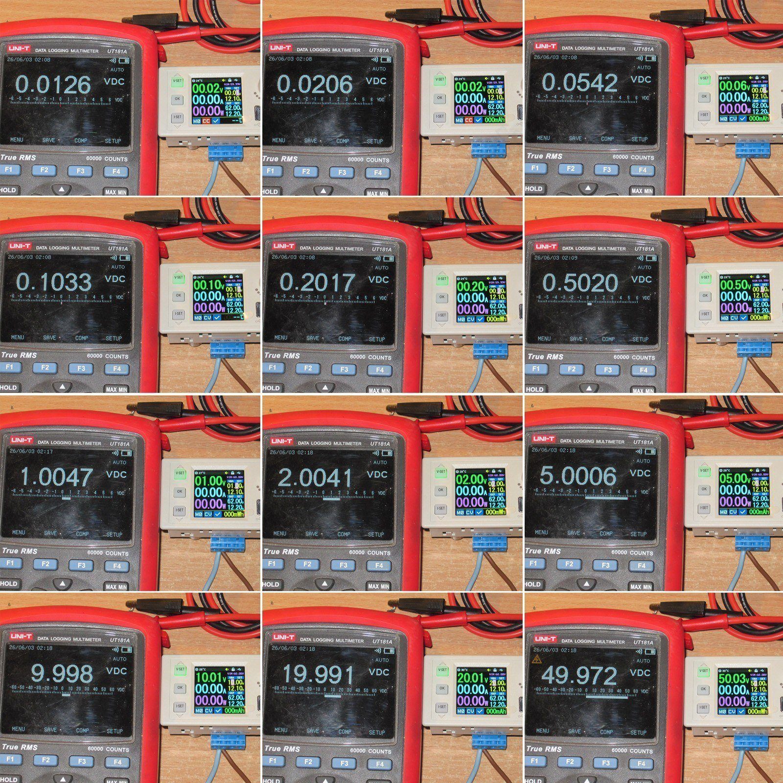
Test two: output voltage setting accuracy, measured with a multimeter, and the accuracy of the converter’s built-in voltmeter, as shown on its display.
I tested from 0.1 to 50 V using the standard 1-2-5 sequence.
There is some measurement error, but it only shows up at the very beginning and very end of the range. Interestingly, right at the end, the output voltage reads low while the built-in voltmeter reads high.
Near the very top of the range, the output is 30 mV low and the voltmeter reads 30 mV high, giving a total error of 60 mV. But if you do the math, that’s only 0.1%—not bad at all, in my opinion.
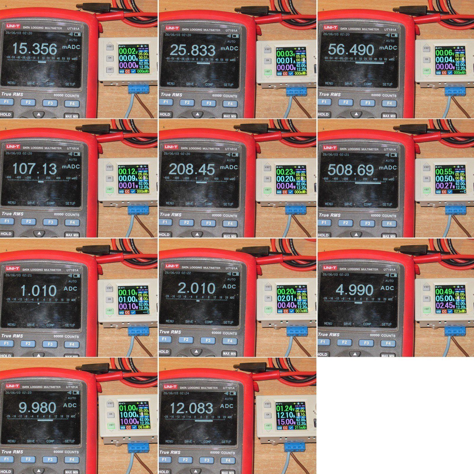
Test three is more complicated: current setting and measurement accuracy. The method is the same as above, except that the final current is only 12 A.
Up to 2 A, the current reads slightly high, but only slightly. Above that, it reads a little low, though nothing critical. For such a small, powerful converter, I think that’s actually pretty good—it’s not a calibrator, after all. What’s more interesting is that up to and including 2 A, the current reads high by roughly the same amount, regardless of the set value.
Test four: how the output voltage varies with current.
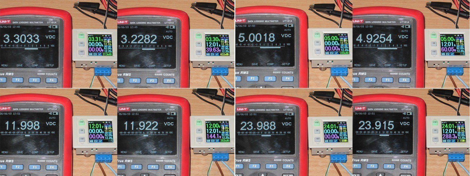
I tested at four voltages—3.3, 5, 12, and 24 V—with no load and at the full rated load.
Somehow, my results here were worse than with the 6006. Back then, it was around 10 mV; here, I got closer to 75–80 mV. Maybe there’s more voltage drop across the terminal block; I didn’t investigate, but the results are shown in the photo below.
In this test, the converter was a bit disappointing. At full current, you get about 0.1–0.09 V less than the set value. I may experiment with it some more later, but I doubt it will get any better.
Test five: minimum voltage drop across the converter.
The description had two footnotes about ripple: it was measured with the bandwidth limited to 20 MHz and with a 0.1 µF capacitor connected in parallel with the probe. But that’s standard practice, as I’ll show later.
The second footnote was about the minimum voltage headroom, and it was worded rather unclearly. But here’s an example: with 24 V at the input, don’t expect more than 20.8 V at the output. That seems rather optimistic to me.

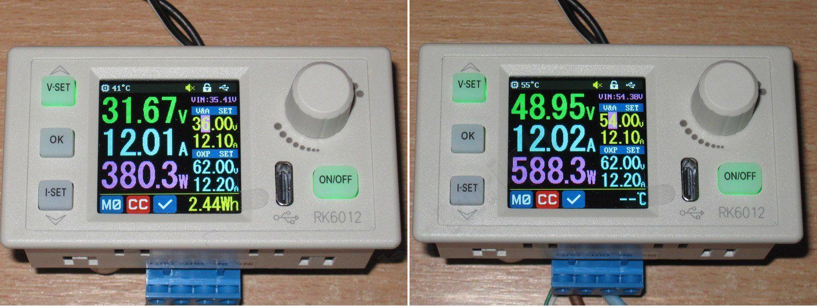
The test is very simple: apply 36 or 55 V to the input. In reality, that leaves us with 35.41 and 54.38 V. Then set the output voltage to a level the converter definitely can’t regulate anymore, and calculate the difference. Naturally, the test is done under full load.
With 35.41 V at the input, the output was 31.67 V, a difference of 3.74 V.
With 54.38 V at the input, the output was 48.95 V, a difference of 5.43 V.
That’s about it. So, if you need a full 61 V, the power supply should be rated for at least 67–68 V. Of course, you could call the specs misleading, but to be fair, they don’t say what current the results were measured at.
Test six: ripple.
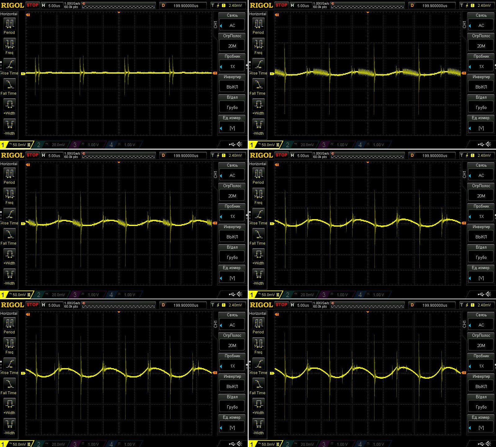
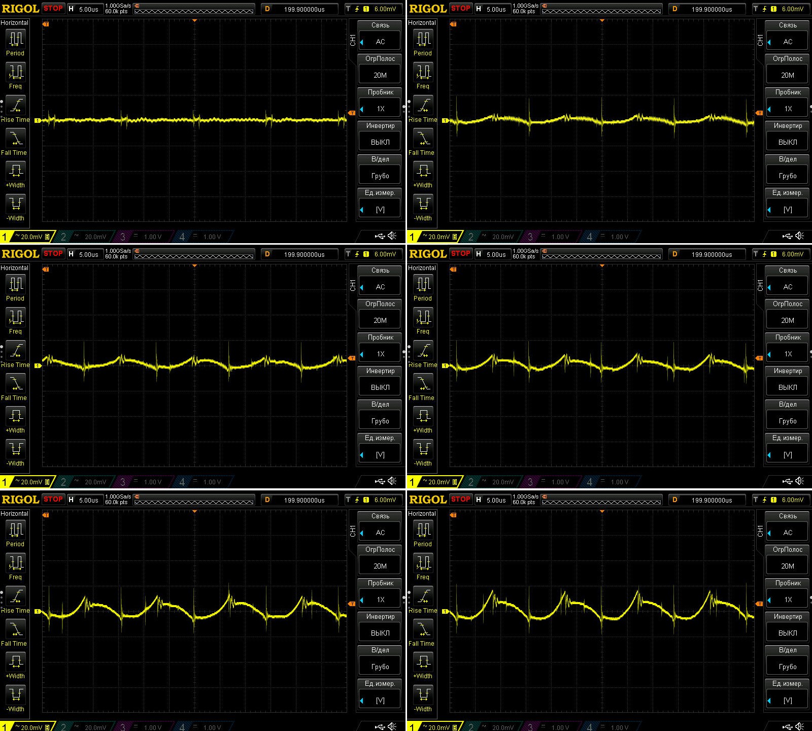
In the first part, I tested it with no load and at currents of 2.5, 5, 7.5, 10, and 12 A, at 30 V, averaging over the full range. The specified ripple is 100 mV peak-to-peak, again with no operating conditions given.
First, I connected the probe directly to the converter output, without anything else, and I can’t say I liked the results. The 6006 looked better with exactly the same measurement.
What I didn’t like were these spikes, since the main part of the ripple stayed well within 100 mV, closer to 50 mV.
All right, I used my usual probe tip adapter, with the standard combination of a 0.1 µF ceramic capacitor and a 1 µF electrolytic capacitor, and got a completely different result, which matches the spec.
Yes, strictly speaking, the correct way to measure is with this kind of two-capacitor setup. Riden’s engineers use only a ceramic capacitor, but that doesn’t make much difference, since it’s mainly the ceramic capacitor that suppresses these spikes.
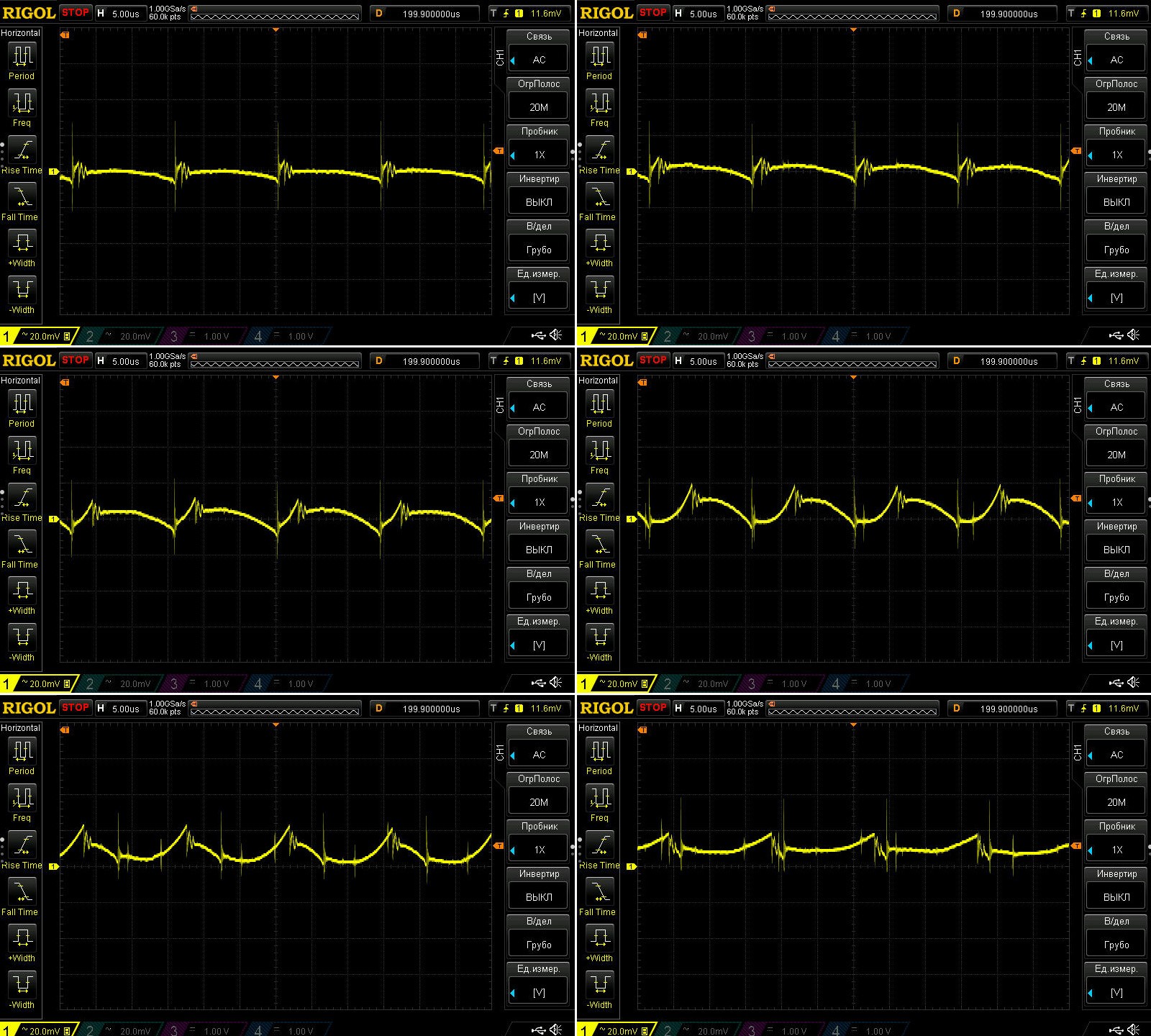
The second test was also a standard one for my reviews. The current was the same throughout, 12 A, but the voltage varied: 3.3, 5, 12, 25, 40, and 53 V. The input was 61 V in every case.
For the most part, with the 0.1 + 1 µF combination, the ripple stays within the specified 100 mV. The spikes are just a little higher at 3.3 and 5 V.
In my opinion, even though there’s an inductor at the converter output, the output here is noticeably noisier than on the previous model. It might be worth removing the board and soldering ceramic capacitors across the output capacitors.
Test six: transient response.
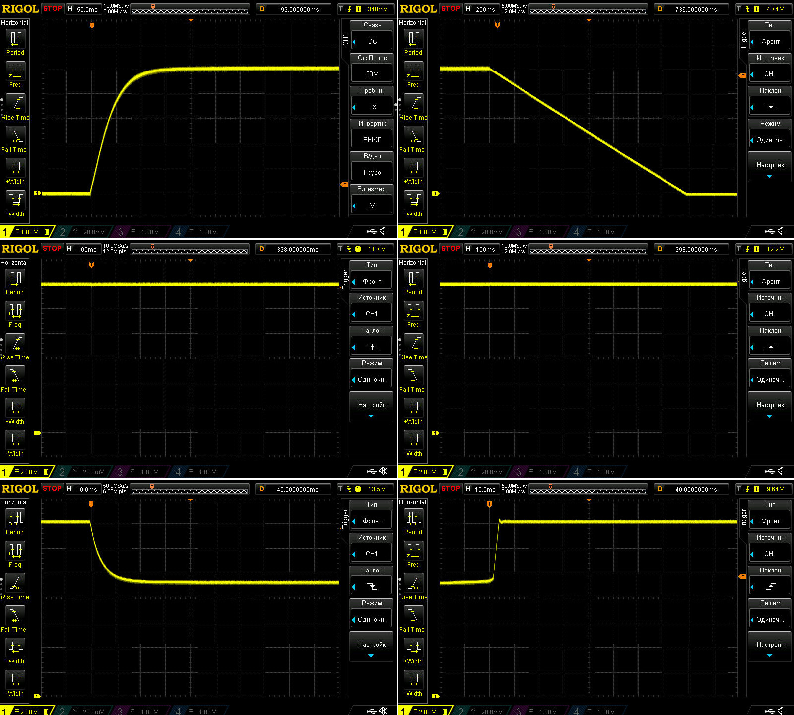
The tests were performed in different operating modes:
1, 2. Applying/removing 5 V at the output.
3, 4. Response to connecting/disconnecting a load. The output was set to 12 V, with a 30 Ω resistor connected continuously and a 3.3 Ω resistor connected in parallel with it (or disconnected). So this tests the response to a current step from 0.4 to 4 A and from 4 to 0.4 A.
5, 6. Switching from CV mode to CC mode and back, at 14 V, with a 4.5 A load current and the current limit set to 3 A.
The converter handled all the tests very well. The only unusual thing was how gradually the voltage dropped when switched off: it fell linearly from 5 to 0 V over 1.6 seconds. I’d guess the discharge circuit (often a current regulator) is relatively low-power, so just keep that in mind.
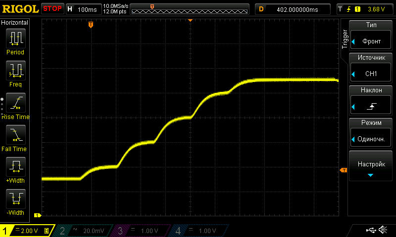
I didn’t do the “soldering iron” test, since it was already clear this model would pass it without any trouble. Instead, I checked its response to voltage adjustment. Below is the waveform while adjusting from 3 to 11 V. There should have been more steps, but in practice, because the adjustment was so fast, it went like this: 3-4-6-8-10-11 V. But in any case, I didn't notice any spikes, including when power was applied to the converter. Everything works correctly.
Test seven: evaluating the converter's efficiency.
Here I checked the efficiency with an input voltage of about 61 V, a load current of 12 A, and output voltages of 5, 12, 24, 36, 48, and 54 V.
Let's also compare it with the 6006 model.
Output voltage — efficiency — power loss
5 V — 88.8% — 7.57 W
12 V — 94.3% — 8.63 W
24 V — 96.7% — 9.83 W
36 V — 97.8% — 9.8 W
48 V — 98.5% — 8.56 W
54 V — 98.8% — 7.64 W
Almost the same operating conditions, except for the current and maximum voltage, for the 6006.
Output voltage — efficiency — power loss
5 V — 83.4% — 6.3 W
12 V — 91.8% — 6.4 W
24 V — 95.3% — 7.0 W
36 V — 96.8% — 7.2 W
48 V — 97.6% — 7.1 W
56 V — 97.9% — 6.8 W
You can see that the new model is clearly more efficient. The power losses are higher, of course, since its power rating is twice as high, but I should point out that the losses increased by much less than the power did.
Test eight: temperature rise.
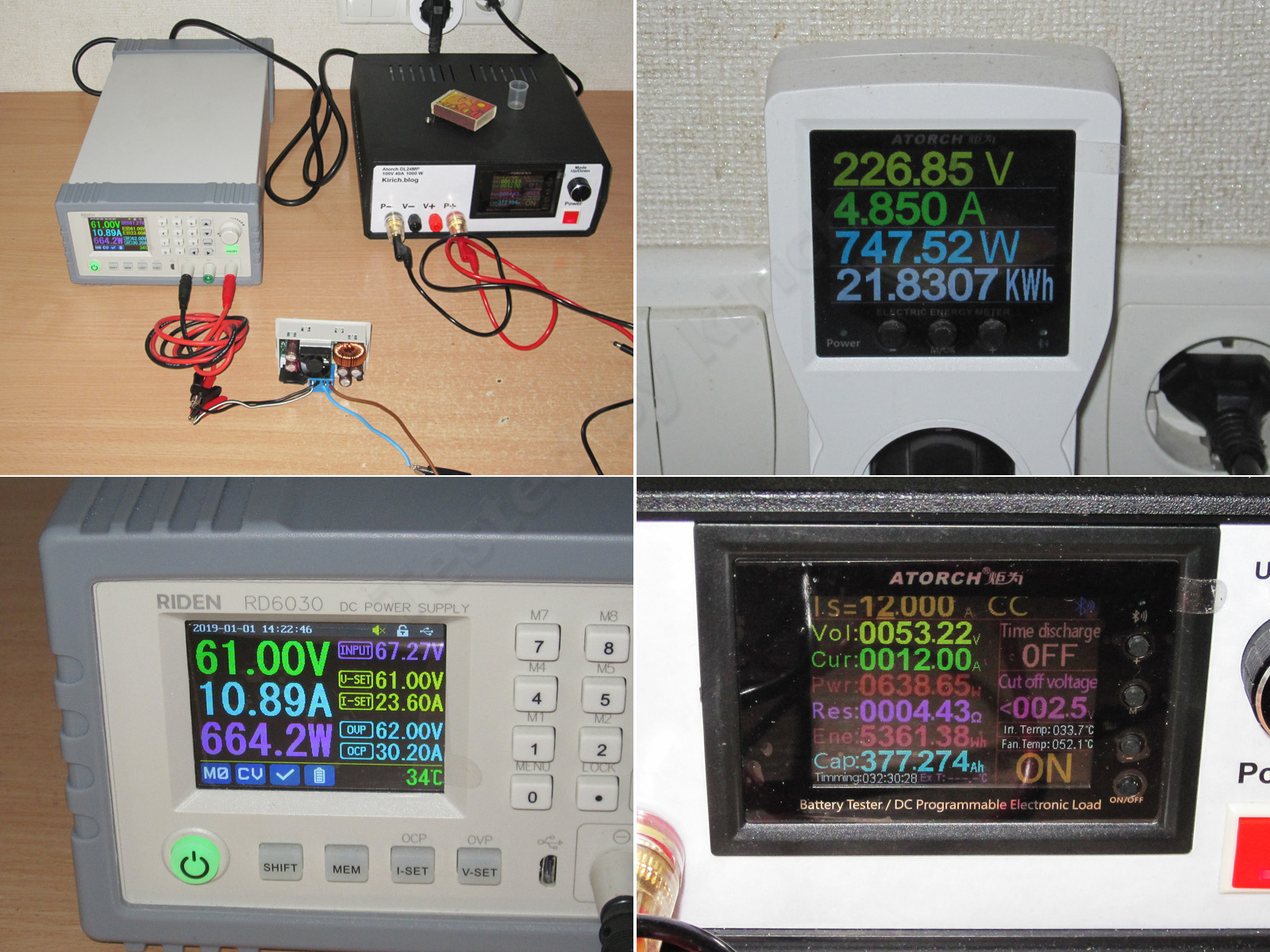
I put together a simple test setup, fed about 61 V into the converter, set the output to 54 V, and loaded it at 12 A. That gave an output power of almost 648 W out of the 720 W maximum.
The power readings worked out like this: 747 W drawn from the mains, 665 W reaching the output of my power supply, 648 W at the output of the unit under test, and just 638 W reaching the load. The rest was lost along the way.
In fact, the losses were higher at 24 V than at 54 V—I only realized that later—but the difference wasn't all that large.
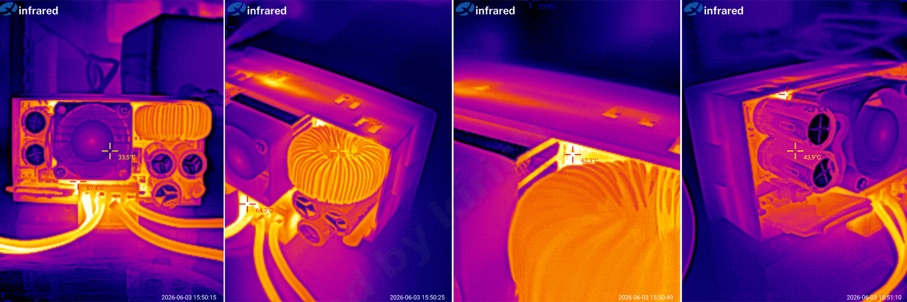
I let it run like this for a while to warm everything up, then took a look.
1. It was about 67 °C somewhere between the terminal block and the heatsink.
2. The power inductor was at 50 °C.
3. Somewhere between the inductor and the heatsink, the temperature seemed to be 62 °C.
4. The highest temperature I found was 77 °C, on the left side of the heatsink—or, more precisely, underneath it.
In any case, the converter performed very well. The fan made a little noise, and it didn't get too hot.
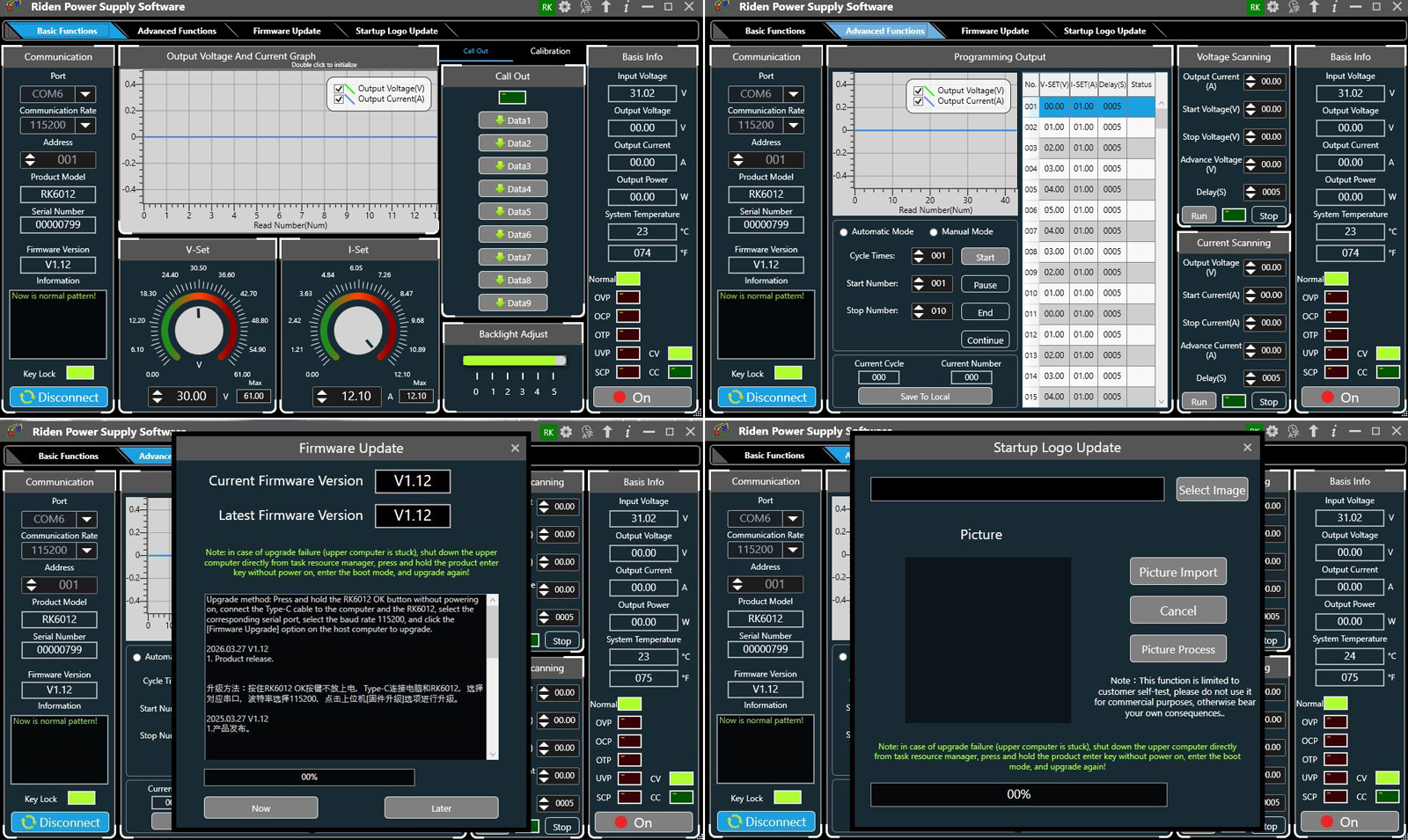
I downloaded and installed the software, updated it as usual, launched it, and would like to say there were some noticeable changes, but I didn't spot any right away. Then again, it's already quite feature-rich.
Conclusions.
Overall, Riden has come up with another predictably good converter. Decent accuracy, high efficiency, moderate ripple, compact size, and a standardized case—but there were a couple of things I didn't like.
There were two things I didn't like. The first, and most important, is the relatively large voltage drop under load. It seems to occur at the terminal block, since the converter itself thinks everything is OK. The second is that switching the adjustment step is a bit awkward. I later realized that the RD60xx converters I'm used to simply have two buttons, left and right, so I've gotten used to them. In short, it's just a matter of habit.
In short, it's a pretty good compact converter with an output power of up to 720 W. It reminded me of my first ZXY6005: a large board and just 300 W. This one is the size of a pack of cigarettes, has more features, and is two and a half times more powerful.
That's all for today. I hope you found this useful. As for me, I'm waiting for the second package from Riden :)
общий, https://www.kirich.blog/obzory/preobrazovateli/1304-novaya-model-preobrazovatelya-ot-rayden-rk6012
Questions and answers
What is the maximum output power of the Raiden RK6012?
Up to 720 W. With the power supply from the 6006 version, 12 A is available only at voltages up to 30 V; above that, the current must be reduced.
How hot does the Raiden RK6012 get under load?
The highest temperature found during testing was 77 °C beneath the heatsink. The fan made some noise, but the converter did not overheat.
What did the author dislike about the RK6012 converter?
The author noted a noticeable voltage drop under load, apparently at the terminal block, and found the adjustment-step selection for voltage and current inconvenient.
This model is included in the summary table: Comparison of adjustable converters for a bench power supply
The figures from this review are in the measurement database: Converters
Discounted products
You may be interested in


Discounted products
All the content on the site and the advice are free, but we’d be grateful for your support of the project and the channel!
Comments6
Only registered readers can comment. It takes a minute to sign up, and you can log in with the same account you use on the forum.
Log inRegister
Comments are published in their original language.