
A decent 12 W PLF12A-15 power supply from Sanmim
A reminder: to keep up with new posts on the blog, I recommend following me on Instagram. I’ll post notifications about every new article there, and might also write about something interesting from time to time - link to my account
You can also subscribe to updates and new articles on the Telegram channel - https://t.me/KirichBlog
I bought two identical power supplies, both rated at 15 V, for some new electronic loads. In the end, one of them wasn’t suitable. There’s a small discount when you buy a pair. These power supplies are also available on AliExpress for roughly the same price, maybe a little more in some cases, so there’s not much point buying them there unless you have some coupons.
As with the other SMPS units from this manufacturer, there’s a datasheet. It’s quite informative, although it’s in Chinese.
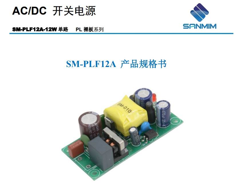
It comes without any packaging, just a plain plastic bag.
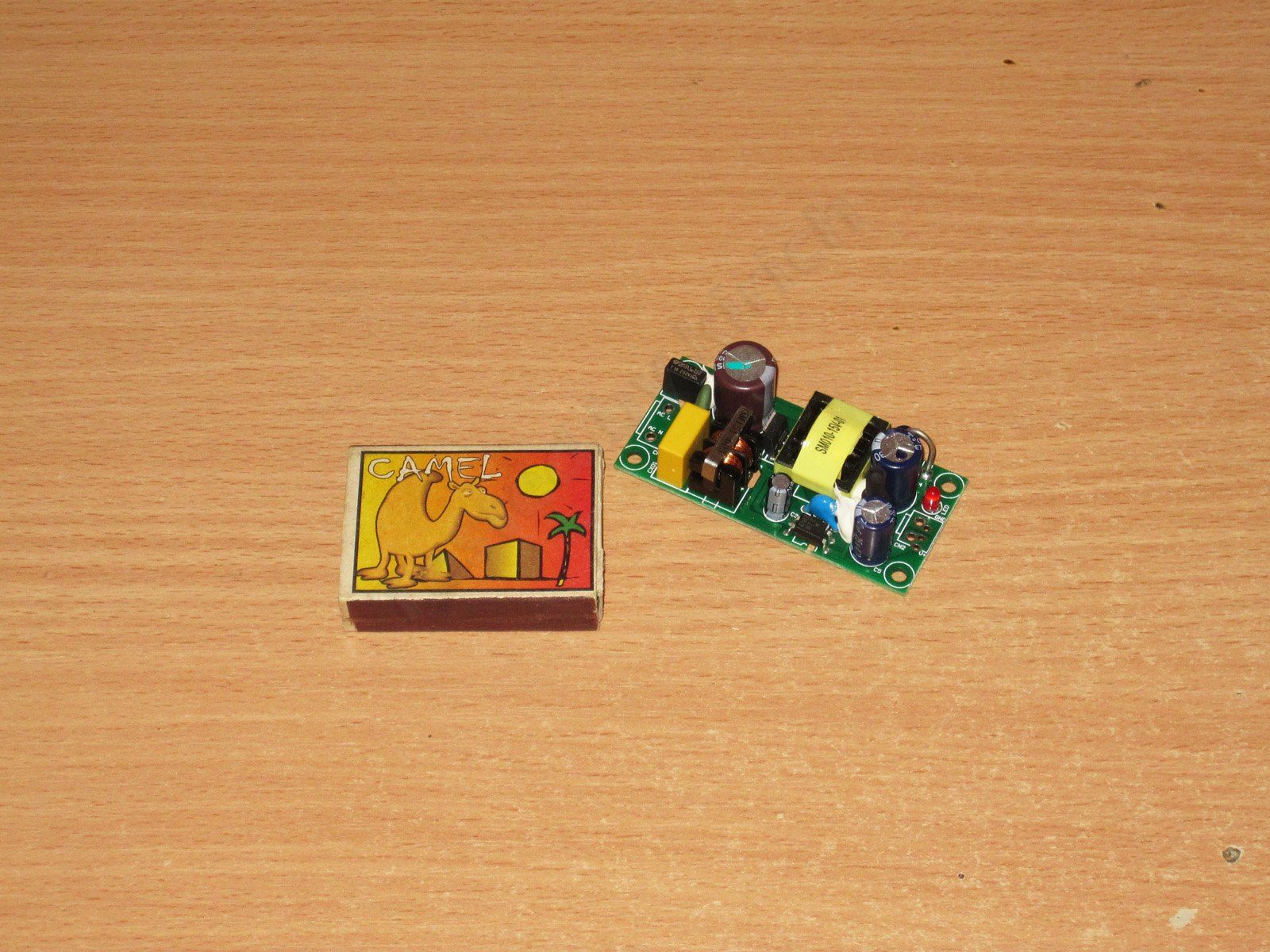
According to the datasheet, there are five versions: 5, 9, 12, 15 and 24 V. The one on my bench is the 15 V version. Note that all versions except the 5 V one are rated at 12 W; the 5 V version is rated at 10 W. This is quite common, though, and is due to its lower efficiency.
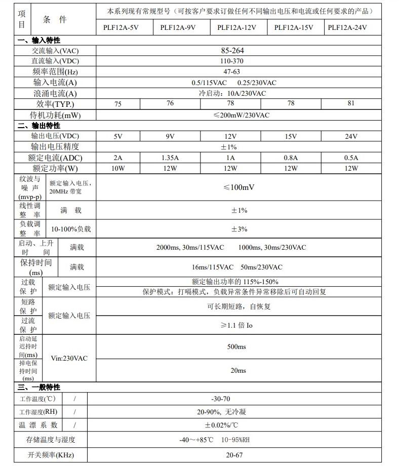
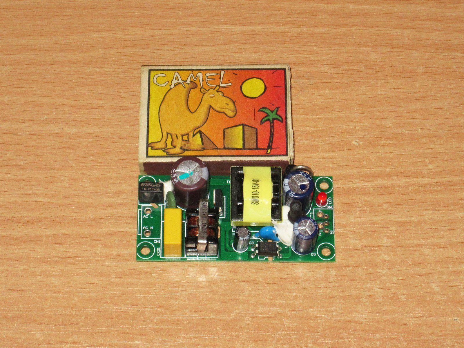
It looks very neat. The board is the classic green color, and everything is straight, attractive and tidy.
The board is a little larger than a matchbox. That’s what caught my eye: I wanted a compact power supply with roughly this much power.
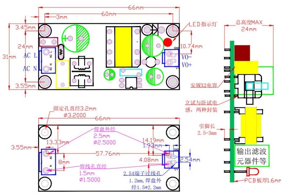
The datasheet includes a detailed (very detailed, actually) dimensioned drawing. Really handy—five stars.
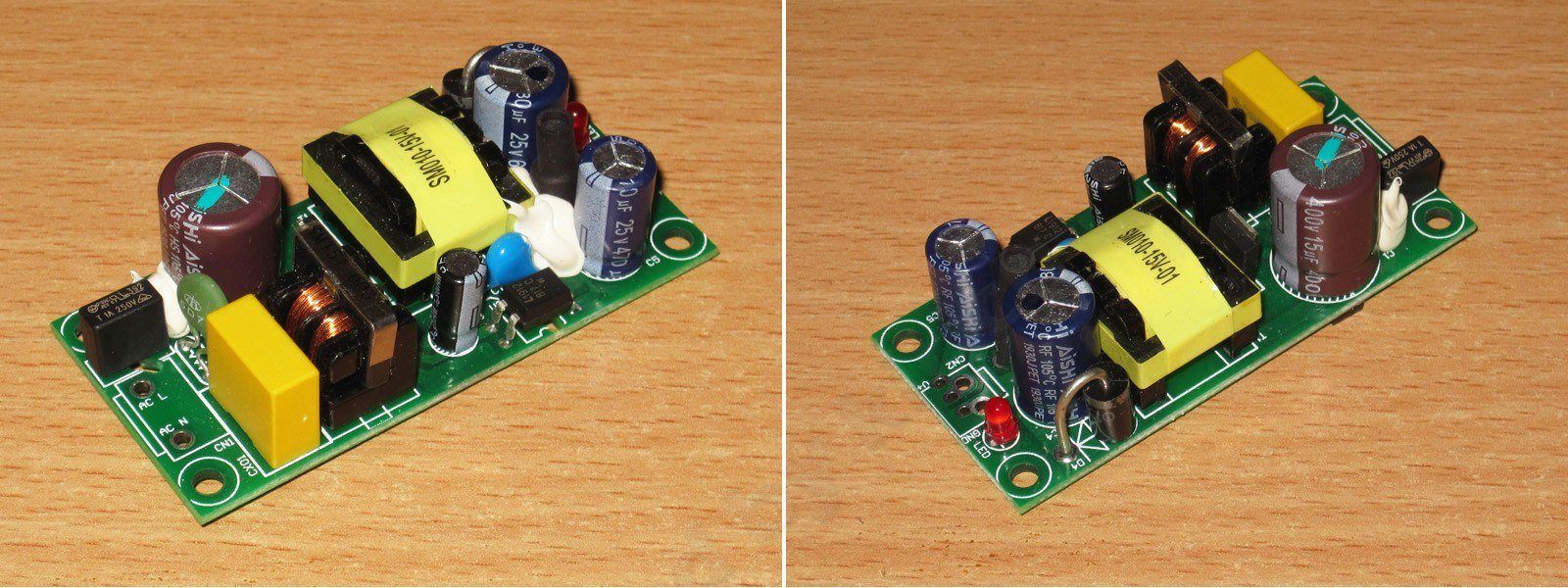
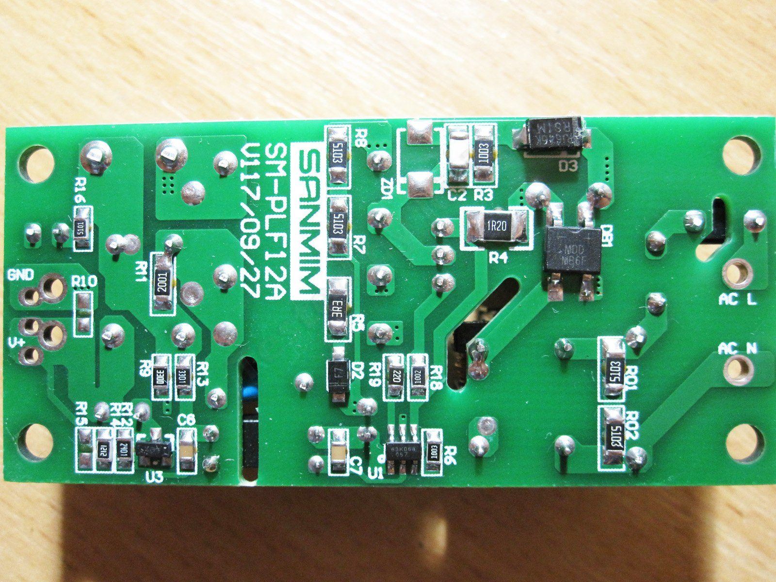
I’ve already reviewed the 6 W version of this manufacturer’s power supply. I use them a lot, but one thing that really annoys me is having to install a fuse because there isn’t one on the unit itself. This one gets that right: there’s an input fuse, thermistor, inductor and X capacitor. They seem to have forgotten only the varistor.
The input capacitor is 15 µF, which is quite enough for our mains supply. All the capacitors are made by Aishi, a pretty good manufacturer.
There’s an inductor on the output to reduce ripple, and two capacitors rated at 680 and 470 µF.

The soldering is neat, the board is clean, and there’s a protective clearance under the optocoupler. Honestly, it’s a pleasure to hold.
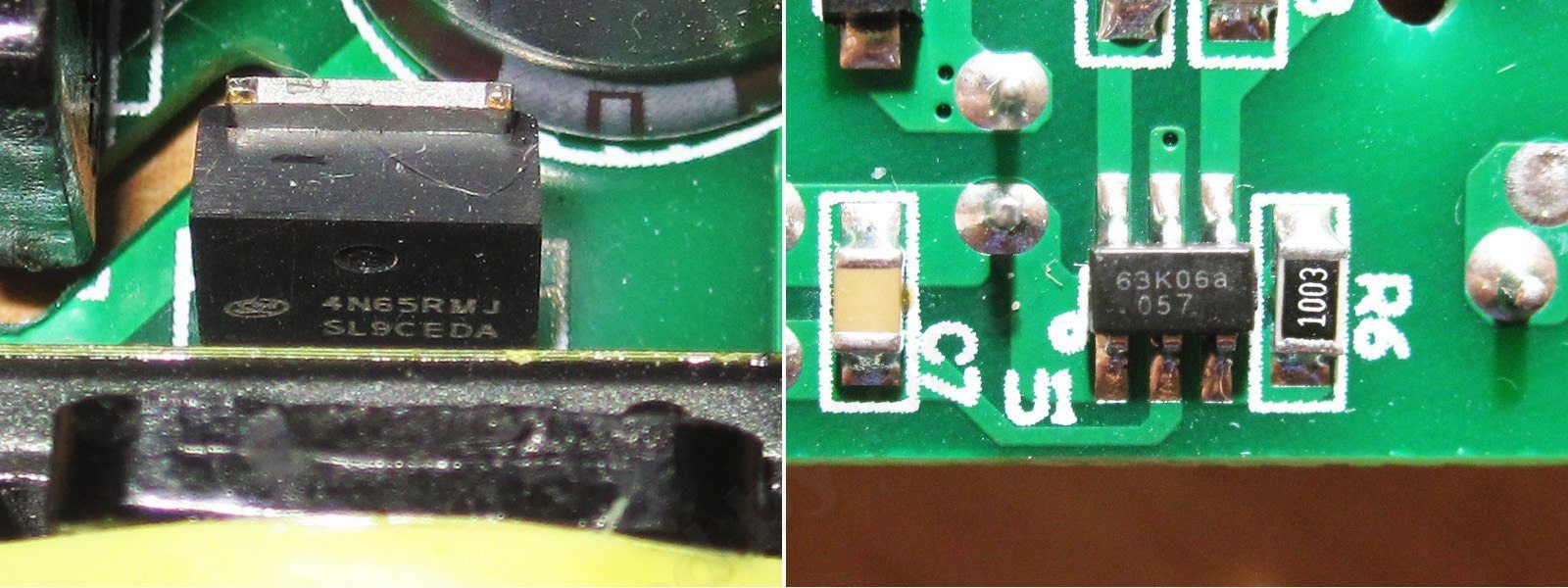
The high-voltage transistor is a 4N65RMJ, controlled by a 63K06A PWM controller.
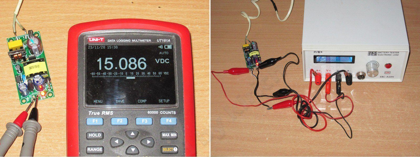
With no load, the output is almost 15.1 V. There’s no output voltage adjustment. I ran the tests with an electronic load using a four-wire connection, wired so that the voltage was measured directly at the board’s output.
With no load connected, my wattmeter reads zero. Unfortunately, my old one burned out before the war, and I don’t really trust the new one. Still, the specified no-load power consumption is about 0.2 W, so I’m inclined to believe it.
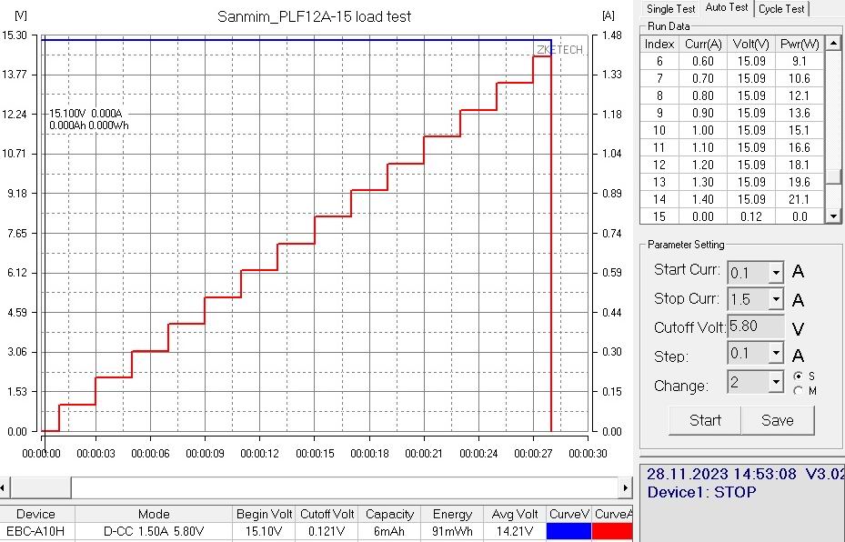
The load test showed, first, that the output voltage is very stable right up until shutdown, and second, that shutdown actually occurs at an output power of 22 W—a generous margin for a 12 W power supply. I was concerned about how it would perform over an extended period: you can load it to around 20 W, but would it hold up?
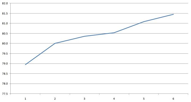
Efficiency is also fine. The specified figure is 78%; at 12 W output, I measured about 80%. I tested it up to 18 W, or 150% load, and efficiency actually increased a little further.
The scale at the bottom is marked in 3 W load increments.
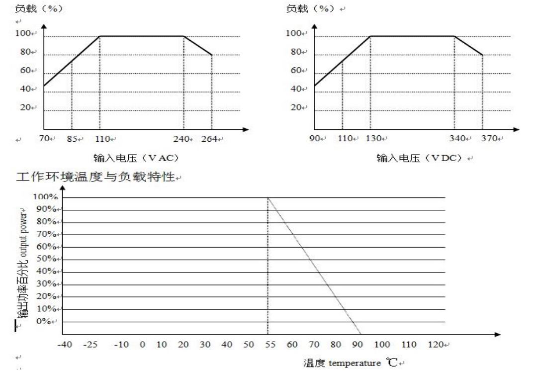
These graphs show the load capacity as a function of input voltage and temperature. They may be a bit hard to follow if you’re not used to this kind of thing, so here’s the simple version:
You can run it at full load with an input voltage in the 110–240 V range. If the voltage is lower or higher, reduce the load.
You can run it at full load up to an ambient temperature of 55°C. Above that, reduce the load linearly.
Since I test at normal mains voltage and room temperature, none of these restrictions apply. And where I planned to use this power supply, there’s active cooling as well.
I planned to start with 20-minute intervals at 50% and 100% load, then test at 125% and 150% for 10 minutes each. But after the 125% load test (1 A), when I increased the current to 1.2 A, the power supply shut down. This indicates that it has overtemperature protection, since the unit worked when cold and delivered up to 22 W.
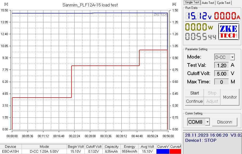
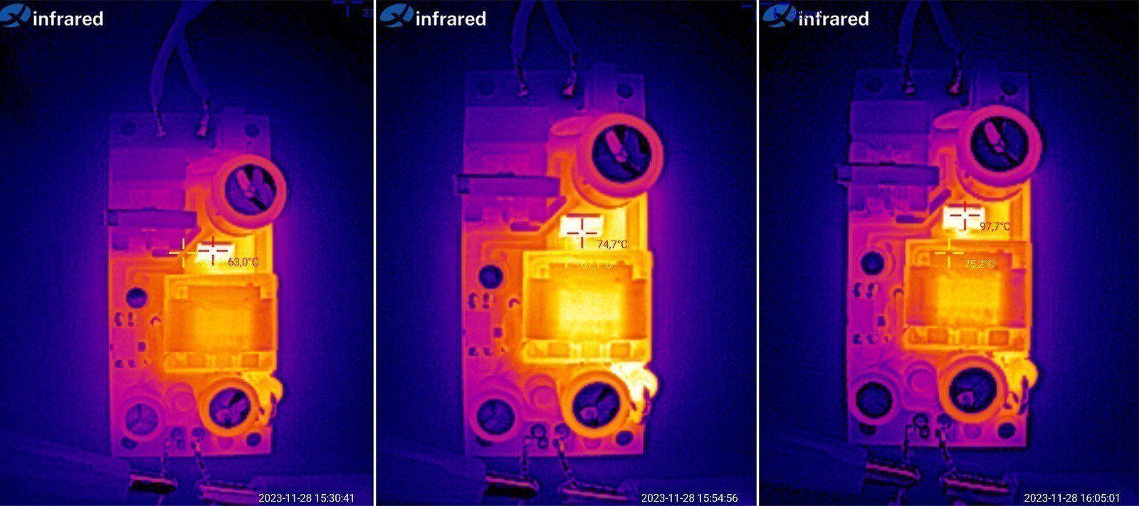
Even so, I can say that the unit handles a 125% load very well. Even under these conditions, the hottest component was the transistor at 97.7 degrees; the other components were cooler, and the transformer stayed below 80, so there’s still some headroom.
The point is, I initially complained about the high overload protection threshold, but the unit handles it just fine.
Thermal images after testing at 50%, 100%, and 125% load.
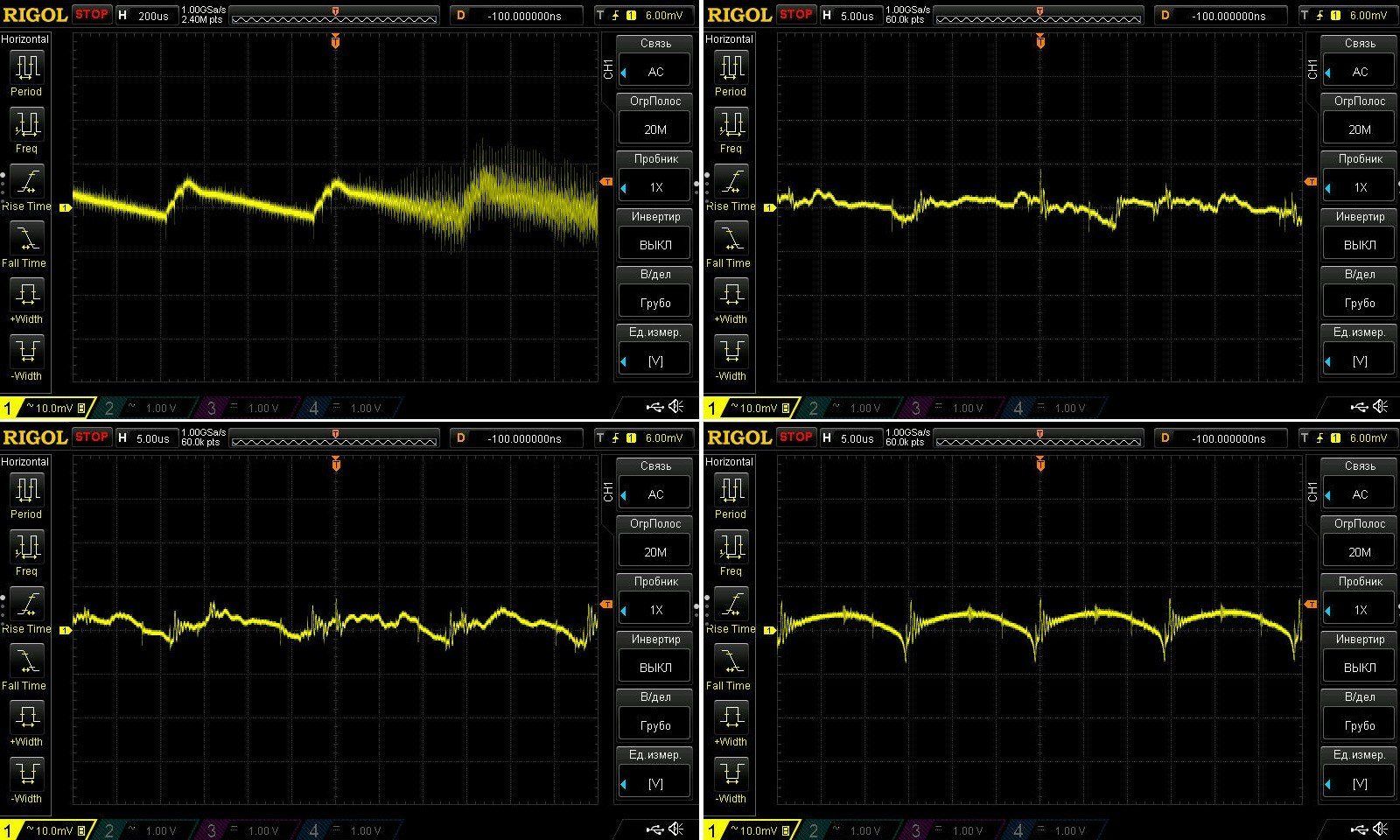
And of course, a test of the output ripple amplitude. The spec is no more than 100 mV for all power supply models.
I tested with no load and at 50%, 100%, and 150%. What can I say? I didn’t even add a C+C input filter, and still got around 15 mV peak-to-peak—a great result.
With no load, the ripple is slightly higher, but the power supply lowers its switching frequency in that condition.
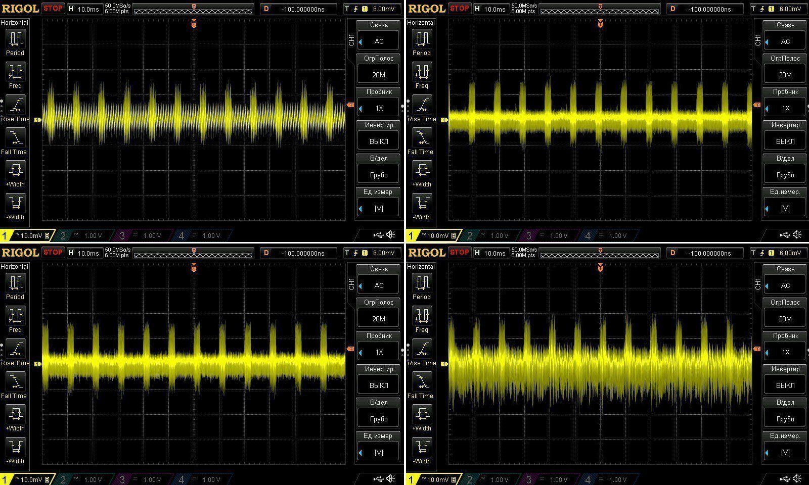
And here’s the low-frequency ripple, where I usually show the full range possible.
Even under these conditions, it came to around 30 mV at 150% output power; at 100%, it was a little lower.
One of these power supplies has already gone into a high-power electronic load, where it powers two fans drawing about 0.8 A in total, plus the control board, for around 0.85–0.9 A altogether. But there was a catch: the fans’ startup current turned out to be very high and triggered the protection. I had to make it a little less sensitive by adding a 3 Ω resistor in parallel with the original 1.2 Ω shunt.
You can just about see this power supply in the photo. It definitely has no cooling problems :)
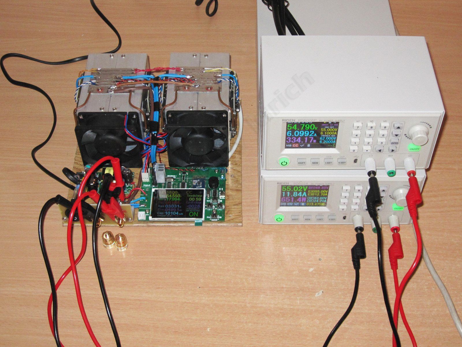
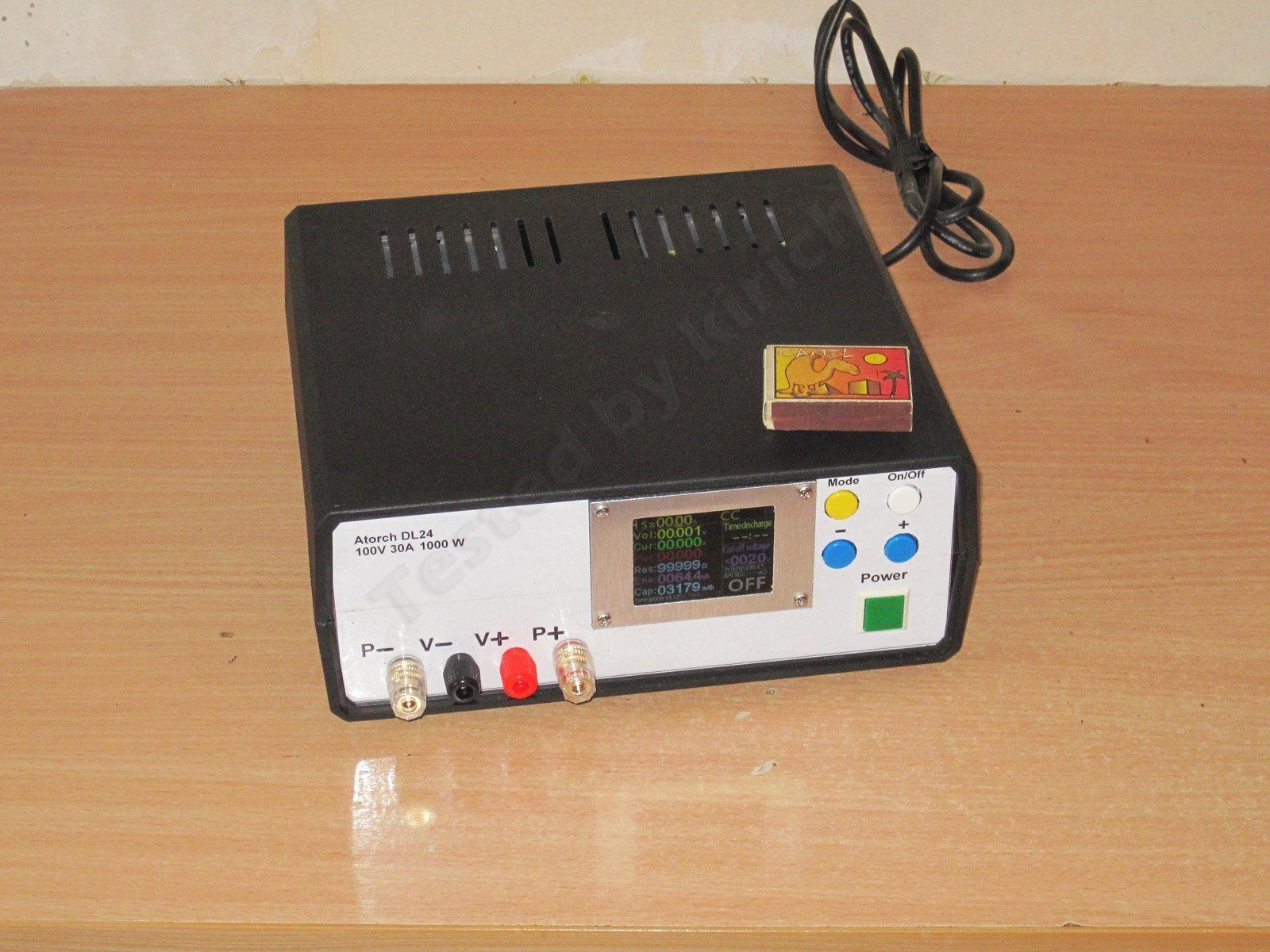
When I built a new 1000 W model, though, this time in an enclosure and with different fans, I had to replace the installed unit with the more powerful GFA20A-12, because the fans I used had an even higher startup current. Reducing the shunt value didn’t help, and lowering it any further would simply have been unsafe.
There’s another possible factor here: this power supply’s protection may respond faster, or perhaps the unit simply shuts off instead of lowering the voltage first, as the SM-PLG06A does, for example.
By the way, I’d like to give a special thanks to one of my readers, who helped mill the display panels :)
Conclusion.
Sanmim power supplies keep impressing me more and more. They’re a very viable alternative to Mean Well units, especially in the mass-market and low-power segments.
Sure, they don’t use Rubycon capacitors, but Aishi capacitors are perfectly decent too. I’d rank them just below the Lelon capacitors used in Mean Well units.
Otherwise, an unequivocal five stars. I recommend buying one.
That’s all for today. Thanks for reading.
5, кирич блог ob2263, 3, sanmim безкорпусний блок живлення схема
Questions and answers
What efficiency did the Sanmim PLF12A-15 achieve?
At 12 W output, the author measured about 80% efficiency; the stated figure is 78%.
How much output ripple does the Sanmim PLF12A-15 have?
The author measured about 15 mV peak-to-peak during testing up to 150% load. Low-frequency ripple at 150% output power was about 30 mV.
Can the Sanmim PLF12A-15 handle overloads?
It ran at 125% load (1 A), but shut down during the extended test after the current was raised to 1.2 A. In a brief test, it shut down at an output power of about 22 W.
This model is included in the summary table: Comparison of power supplies: ripple, efficiency, and temperature rise
The figures from this review are in the measurement database: Power supplies
Discounted products
You may be interested in




Discounted products
All the content on the site and the advice are free, but we’d be grateful for your support of the project and the channel!
Comments7
Only registered readers can comment. It takes a minute to sign up, and you can log in with the same account you use on the forum.
Log inRegister
Comments are published in their original language.