
68 V 600 W Power Supply and a Little More About the RD6006 Converter
$55.89
So, I ordered this power supply on October 27. It cost $55.19, and I had a $2 coupon. I ordered it just three days after the converter, but it arrived about a month later. On top of that, the seller took a long time to ship it. Then, in response to my modest question, "what's going on, bro?", he gave me a tracking number that started showing updates, but a few days later he sent me a different number, most likely the one for my actual parcel.
And on top of all those hiccups, the order seemed to be delivered by courier snails. I was getting tired of waiting.
But it all ended well, and I finally picked up the box with my order from the post office. No complaints about the packaging at all: a cardboard box, an air-cushion "mattress" inside, and a second box.

The power supply's case was so polished and smooth that you could easily use it as a mirror. What's more, there wasn't a single fingerprint on it. It looked absolutely perfect.

The power supply is very similar in size to its "little brothers" rated at around 300–500 W. It's only slightly longer and wider, but noticeably taller, at about 65 mm. The unit weighs almost 1.2 kg without packaging.

The side without the cover also has mounting holes and a label with the specifications: 68 V output voltage and 8.5 A current.
The seller offers a wide range of power supply voltages, and the fact that there was a 68 V model was one of the reasons I bought this one. Of course, I could have gone for the 60 V model and "overclocked" it to 65–67 V, or chosen the 72 V model and stepped it down to the same voltage. But this one just happened to have a more suitable voltage, so I bought it.

There are two power supply options, rated at 500 and 600 W, with a bunch of output voltage options. Interestingly, the seller offers shipping from Russia, but don't get your hopes up: that option is only available for the 500 W, 36 V model... go figure.
Specifications listed on the product page:
1. Input voltage: 100–120 VAC or 200–240 VAC, single input voltage
2. Output voltage: 12 V, 13.5 V, 15 V, 24 V, 27 V, 36 V, 48 V, 60 V, 68 V, 110 V
3. Output current: 0–50 A
4. Operating frequency: 47–63 Hz
5. Protection: short circuit, overload, overvoltage, overheating
6. Heat dissipation: cooling fan
7. Operating status: green indicator
8. Weight: 1.5 kg
9. 2-year warranty
10. Input power: 500 W/600 W (probably output power after all — author's note)

There's a label on top stating that the power supply has a temperature-controlled automatic fan function. Below it is a warning to check the 110/220 V input voltage switch, although there isn't one on this unit.
The warranty seal partly explains why the seller took so long to ship my order. I ordered it at the end of November, and the label shows a manufacturing date of November 2019. I assume the seller collects orders and then sends them to the factory, where a batch of power supplies with the required specifications is made. After all, the differences between them aren't that significant, and are mostly in the secondary circuit.

A terminal block with a cover; to its right are the output voltage adjustment resistor and an LED indicating that output is present.

The cooling system is active, as you'd expect for a power supply like this. But unlike less powerful units, the fan here blows inward, drawing air into the power supply. The hot air exits through openings near the terminal block and on the side. One advantage of this cooling arrangement is a longer fan life, since it moves cool air rather than hot air, as in the first case.

The inside is very neat and well laid out.

What's more, this is one of those rare cases where the product page photos almost perfectly match what actually arrived. The only difference is the output section: mine has one diode assembly, while the product photos show two. They probably photographed a lower-voltage model with a higher current rating, which would explain the two assemblies. The seller's photos also show a 110/220 switch and slightly different-looking capacitors.

I didn't draw a schematic of this power supply, so I'll make up for that with a few more photos and a slightly more detailed description of the individual sections.
1. The input filter is almost fully populated. It has a common-mode choke and two X capacitors, but the fuse is tiny, and they completely forgot the varistor, even though there's a spot for one.
2. A heatsink is fitted to the bridge rectifier; the 5D-20 thermistor is visible nearby.
3. The input capacitors are rated at 1000 µF, 200 V each, so in series they provide 500 µF at 400 V—quite acceptable for a “narrow” input range.
4. The circuit board has two terminals for connecting a 110/220 switch, but nothing is connected to them. Perhaps that’s actually better and more reliable.
I’ll point out right away that the board is made of fiberglass, not cheap phenolic paper, which has become rather uncommon lately.

The first thing that catches your eye when you look inside is the number of transformers. Usually there are two: the main transformer and one for driving the transistors. Here there are four.
The reason is that, unlike the familiar power supplies built around the ever-present TL494, this one uses a separate small converter to power the PWM controller and fan instead of a self-starting circuit. Its output voltage is 12–13 V; I don’t remember the exact figure.
A big advantage of this approach is that, if you want, you can make an adjustable power supply with a range starting almost at zero, since the PWM controller’s supply voltage doesn’t depend on the output voltage. I even had the idea of doing that.

Another transformer measures the current in the primary circuit of the main transformer. This is another difference from other power supplies, where current is measured using a shunt in the secondary circuit. Personally, I prefer the shunt approach, but the manufacturer probably chose this design for standardization: the shunt rating has to change depending on the output current, while the same transformer can be used in every version.
Also note the wire gauge of the main transformer’s primary winding. It’s clearly wound in two layers, since it’s split into two half-windings.

The PWM controller isn’t a TL494 either; it’s an SG3525D, which is quite unusual in power supplies like this—or in most others, for that matter. There’s an LM358 op-amp nearby. At first I thought it was responsible for current measurement, but the truth is both simpler and more complicated: the thermistor voltage is fed to both op-amps. One op-amp controls the fan; its signal then goes to a transistor (between the connector and the trimmer). The other op-amp shifts the signal from the transformer, and the current trip point depends on the temperature.
One design drawback is that the thermistor is “hanging in the air,” so it essentially measures the ambient temperature, since there’s nothing between the fan and the thermistor that generates a lot of heat.

The transformer is marked
The transformer’s core looks more interesting than the ones in more familiar Chinese power supplies.

The output stage has a large inductor, four 100 µF, 200 V capacitors, and a diode assembly mounted on a heatsink. A 10 kΩ load resistor is also visible.
The capacitors are quite large for their capacitance, so I’m inclined to believe they really are rated for 200 V. I have a Samwha RD 470 µF, 100 V capacitor of the same size.

1. The input bridge rectifier is a GBJ1506, rated at 15 A, 600 V.
2. The output uses an MUR3060NCT. I couldn’t find a datasheet for it; searching for MUR3060 only brings up individual diodes, but I did find a description of MUR3060PT, which says it contains a pair of 15 A diodes.
3. Two 2.2 µF, 400 V capacitors are connected in parallel in series with the transformer.
4. The board is marked FST-600 17.02.09

The diode assembly is mounted on a heatsink that doesn’t make contact with the case, which is also fairly unusual. There’s room on the heatsink and circuit board for two more assemblies, presumably for a higher-current version of the power supply.

The board comes out of the case very easily: you just need to remove the four screws securing it to the case and one screw holding the inverter’s power transistors in place.

While unscrewing the transistors, I noticed that the cover was secured not in holes in the case, but in specially pressed-in bosses.
The inverter uses a pair of 25N50T MOSFETs. The closest similar part I could find is the FQA25N50, rated at 23.5 A, 600 V.

The transistors are driven through an isolation transformer (on the left) and a very simple driver made up of a diode, a transistor, and three resistors. The circuit is primitive, but it noticeably helps the transistors turn off faster. I described a similar one some time ago.
The auxiliary power supply is visible on the right. It uses cheap Chang capacitors on the output, which will probably need replacing, but at least they added an inductor to reduce ripple.

The PWM controller and op-amp section. Only later did I notice that resistor R30 actually does nothing: its lower lead goes nowhere because zener diode ZD1 isn't installed.

Overall view of the top of the board

And the bottom, of course.

Overall, the soldering is reasonably good, but I did find one little flaw: a couple of leads were touching. Continuity testing showed there was no electrical contact, but I separated them just to be safe.

As I usually mention in my reviews, when a power supply uses "no-name" Chinese capacitors, they will most likely have their stated capacitance, unlike capacitors labeled Rubycon, Nichicon, and the like.
That turned out to be the case here, too. The input capacitors are almost 1000 µF, and the output capacitors are almost 400 µF (4 × 100). Measuring them in-circuit skewed the results, but I think their actual capacitances are 1000 and 100 µF, respectively.
The input capacitors can be up to 30 mm in diameter; the ones installed now are about 25 mm. They're almost 50 mm tall, but you could try to "squeeze in" 55 mm ones.

Let's move on to the tests.
First, let's check the output voltage and its adjustment range.
It was initially set a little higher than specified, though that's not critical. The full adjustment range was 62–81 V. When I tried to set it to exactly 68 V, I found that the voltage drifted slightly upward: I'd set it to 68 V, and a minute later it was already at 68.06 V. A small thing, but annoying.
I should also note that the power supply makes a noticeable buzzing sound with no load, but even a small current makes it stop.

For the remaining tests, I used my main electronic load. Since its maximum input voltage is only 50 V, I had to set the output to 62 V (I've used it at this voltage before, and the load handled it). But since it can only measure up to 50 V, its display showed not the actual power, but current × 50 V.
With no load, the power supply draws about 6 W. The fan starts immediately, but the voltage across it is only about 6.5–7 V.
I noticed an interesting glitch: 61.92 V with the load disconnected, exactly 62 V with it connected. The load draws only a small current, but for it to affect the output voltage that much...

Efficiency was measured at an output voltage of 62 V and load currents of 1–10 A. The efficiency turned out to be quite good, but by the end of the test the output voltage had risen from its initial 62.00 V to 62.42 V.

The test for response to an output power overload was just as strange. Using two loads, I drew 12 A from the power supply, or about 750 W, but the protection showed no sign of tripping.

I ran the thermal test with the cover off, since removing it "on the fly" is a bit dangerous. But I covered the top and side with boxes to simulate the cover without disrupting the airflow.

The test ran under the following conditions:
20 minutes at 3 A, 186 W
20 minutes at 6 A, 370 W
20 minutes at 8 A, 500 W.
1. At the very start of the test, the snubber circuit, fan control transistor, transformer, and part of the output inductor stand out in the image.
2. After 20 minutes, you can clearly see the primary-side snubber heating up, along with the two components parallel to the output diode assembly and the thermistor.
3. The primary-side snubber gets extremely hot. At an output power of 186 W, the resistors were around 176 °C.

1. After another 20 minutes, the heat distribution hadn't changed much; the snubbers and thermistor were still heating up.
2. But the resistors in the high-voltage snubber were already above 200 °C.
3. At the end of the test, things were much the same; only the temperatures had changed. The transformer, for example, was barely warm: at 500 W, it reached just 52 °C.

A closer look at individual components.
1. Inverter transistors: 56 °C
2. Primary-side snubber: 240 °C.
3. Snubbers parallel to the output diode assembly: 132 °C; output inductor: about 60 °C.
I have to say, the temperature distribution is very strange. Usually, the transformer and output inductor get hottest, followed by the inverter transistors and output diodes. Here, all these components stay below 60 °C at 500 W, but the snubber resistors get hot, especially on the primary side. Still, 240 °C at 500 W output is a bit much.

Checking how the output voltage varies with load and temperature.
1. Before startup, with no load.
2. After 25 minutes at 3 A
3. Increased the load to 6 A
4. After 20 minutes at 6 A
5. Increased the load to 8 A
6. After 20 minutes at 8 A
Over an hour of warm-up, with the power ranging from 0 to 500 W, the voltage dropped by 0.7 V, or a little over one percent. Not a lot, and tolerable, but I still don't like it.

1, 2. At the end of the warm-up: output current 8 A, power about 500 W, input power 578 W, efficiency about 87%.
3, 4. I removed the load. It turns out most of the voltage drift was temperature-related, about 0.6 V. After 10 minutes of running with no load, the voltage returned to its original value.

Measuring output voltage ripple in different operating modes.
I used a single load here, since the test was brief.

The test was performed in four modes: no load, and at currents of 3, 6, and 10 A, corresponding to 205, 410, and 620 W.
For a power supply with this output voltage and such a small output capacitance, 150 mV peak-to-peak ripple at 620 W is simply excellent.

At 100 Hz, the ripple looks more concerning because of the short spikes, but the main component is around 300 mV. Even the full peak-to-peak value, including the short spikes, stays within 650 mV, or about 1% of the voltage.

I'll sum up my conclusions about the power supply at the end of the review. For now, let's move on to a small modification and some explanations.
Throughout the review, I've often mentioned something called a snubber. I'll try to explain what it is in simple terms.
A switching power supply constantly switches transistors and transfers energy to the transformer, then from the transformer to the load. But we live in an imperfect world, and the components are imperfect too.
When energy is “pumped” into the transformer and then transferred to the load through the output diodes, there's a short pause caused by two things:
The transformer itself isn't perfect
The time it takes for the output diodes to turn on.
Because of this, when the transistors turn off, a short voltage spike appears on the transformer's primary winding. It's best to suppress it somehow, and that's what snubbers are for: they “absorb” the spike, like shock absorbers in a car. A simple snubber is an RC network, shown on the left in the schematic. Similar networks are also connected in parallel with the output diodes to reduce switching noise and, in part, to take the initial “hit” before the output diode turns on.
In the end, the snubber converts all the “extra” energy into heat. The amount of heat also depends on how well the transformer windings are coupled. To improve coupling, the windings can be interleaved, with the primary and secondary layers alternating. It's also preferable for the winding wire to fill the entire bobbin area, and to wind the transformer with several thin wires rather than one thick one.
Snubber heating also depends on how “fast” the output diodes are: the sooner they turn on, the more energy the output capacitors absorb. That's why it makes sense to use Schottky diodes even at high voltages, where conventional diodes might seem suitable, since their forward voltage drop is already comparable.
Calculating a snubber “by the book” isn't very convenient, so people more often use an “empirical” method: simply selecting components based on experience from modeling other power supplies and their characteristics, primarily their power rating and transformer.

With AC, a capacitor can be treated as the equivalent of a certain resistance. Knowing the resistance and voltage lets us calculate the current and the power dissipated by the snubber resistors.
As supplied, the snubber here consists of two 51 Ω resistors connected in parallel and a 4.7 nF capacitor. The inverter operates at 70 kHz. At this frequency, the capacitor's reactance is about 483 Ω, which at 150 V (this is a half-bridge) gives a current of 0.31 A.
The resistors have a combined resistance of 25.5 Ω. At 0.31 A, the voltage drop is 7.9 V, and at 7.9 V and 0.31 A, the snubber resistors dissipate 2.45 W, or about 1.2 W each.
This is a very rough calculation, since it doesn't account for many factors, including the nonsinusoidal current, spikes, and so on. I also didn't include the snubber resistors themselves when calculating the current. But it was good enough for an estimate.

I didn't want to make major changes, so I decided to replace the original capacitor with a 3.3 nF one, again using an empirical approach.
Since its AC impedance is proportionally higher, the current should also decrease, and consequently the resistors should run cooler. But I should emphasize that this is a very rough method.

I desoldered the capacitor from some name-brand power supply—it was in the snubber—and decided to replace the resistors with higher-power ones while I was at it.
It may look as though the first band on the old resistors is blue, but that's an optical illusion. It's actually green: the resistors are also 51 Ω, so the color probably changed due to heat.

To understand how the snubber works, the right thing to do would be to measure the spike amplitude on the primary side. But I didn't really want to poke around in there, and it was more important to me that nothing change at the output.
In the end, the amplitude of the “spikes” stayed about the same, or even got smaller. Before the modification is on the left, after on the right.

The resistors did run significantly cooler, though. On the left is the previous test at about 390 W; on the right, after 20 minutes of warm-up at 320 W (that's just how it worked out). The difference in temperature is clearly greater than the difference in output power.
But honestly, I'm still not satisfied—I want to do even better. By the way, you could even put this energy to use, for example by adding a bridge rectifier to power something inside the unit, but it's rather inconvenient.

In the end, I made three modifications:
1. Replaced the snubber components
2. Added a pair of 0.1 µF capacitors at the output. One replaced the load resistor, which I removed and replaced with a bunch of SMD1206 resistors mounted on the underside of the board, slightly reducing the resistance in the process. So technically, that's four modifications.
3. Pressed the thermistor against the heatsink for the output diodes. There was even a threaded hole there—most likely they just “optimized” costs. The fan now behaves a little differently: after startup, it gradually speeds up a bit, by just 5–10% from its initial speed.
4. Not really a modification; I just marked which way to turn the trimmer to decrease or increase the protection trip current. I actually tried turning it 10 times and loading the power supply, but the protection never tripped. Though “current limiting” is probably the more accurate term.

Putting it to use.
Originally, I wanted to install the power supply a little differently: without its cover, and with just one fan—either the power supply's exhaust fan or the converter's original case fan. The idea was to have it pull air through the entire power supply.
It's not a bad idea in principle, but after turning the whole thing around in my hands, I decided to install the power supply “as is,” at least for now.
It fit almost perfectly. This is mainly for anyone planning to buy this case with the converter as a “future-proof” setup. In other words, you can buy and use a 600 W power supply, and an 800 W one might even fit.

1. Since the mounting holes were in completely different places, I simply drilled the converter case, tapped it for M3 threads, and screwed in short screws.
2. The fan board fit like it was made for it. What's more, the thermistor even sticks slightly into the power supply case and is definitely cooled by its airflow.
3. The wires caused a problem: the live wire from the switch was too short, so I had to crimp on a replacement.
4. Just to be safe, I adjusted the power supply voltage with the converter and fan board disconnected. You never know. I set the output to about 66.5 V.

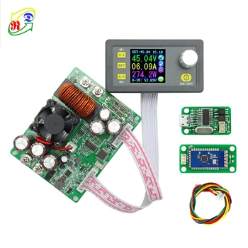
After my review of the RD6006 converter, readers asked me to run some additional tests, so I did.
1, 2. Applying and removing 5 V at the converter output with no load.
3, 4. Response to connecting and disconnecting a load. The output was set to 12 V, with a 30 Ω resistor connected continuously and a 3.3 Ω resistor connected in parallel with it (or disconnected). So this shows the response to a current step from 0.4 to 4 A and from 4 to 0.4 A.
One thing to note: capturing the waveform with the resistor connected took many attempts, because the downward spike rarely appeared (once every 7–8 tries), while the upward spike appeared almost every time.
5, 6. This is a slightly more interesting test: switching from CV to CC and back. The test resistor values are the same, as is the 12 V output voltage. The only difference is that I set the output current so that connecting the 3.3 Ω resistor would put the converter into CC mode. CV–CC is on the left, CC–CV on the right.

I was also asked to run a “soldering iron” test, simulating a relatively low-resistance load being connected and disconnected periodically. For the test, I used a TS100 soldering iron after it had warmed up and reached temperature-maintenance mode.
First, I set the output to 24 V, and it all looked like a simple drop in output voltage. But then I decided to raise it to 25 V to make things clearer, and immediately saw the problem—and how serious it was.
I marked the set voltage of 25 V in red on the waveform. I think you'll notice that the voltage doesn't just sag for a while after the heater is connected; it also rises after the heater is disconnected.
At a load current of about 3 A, the voltage rises by 1–1.5 V and drops by 4 V. In my opinion, the converter failed this test. But I’ve added another very illustrative test to my collection, so thanks to the reader who suggested it.

There was also a question about temperature stability at high voltage and current. I set the voltage to 50 V and the load current to 5 A.
At startup, the voltage was 49.996 V; after 10 minutes, it was 49.978 V, a difference of 10 mV. After disconnecting the load, the voltage rose to 50.02 V, making the difference 40 mV, although in my tests it was usually lower.
In any case, I think it passed the temperature stability test.

From the moment I unpacked the package to drawing my final conclusions, my opinion of this power supply changed several times, swinging from one extreme to the other.
After unpacking, taking it apart, and inspecting it, I thought: actually, not bad. Neat assembly (though not without a few flaws), relatively good-quality components, and a good circuit design. Overall, I liked it.
After the tests: “And this costs more than 50 bucks? I think I overpaid quite a bit. It would probably have been easier to pay a little extra (or maybe not even extra) and get a pair of LRS-350-6 units, connect them in series, and get 700 W from branded power supplies. The only problem would be fitting them in, because of the two fans.” The power supply buzzed with no load, the fan was noisy, the snubbers heated the air, it wouldn’t shut down under overload, and the output voltage changed depending on the load and how much it had warmed up. A complete mess :(
After a small modification and some thought about the test results: “Actually, it’s not all that bad.” The main components (transformer, transistors, diodes, inductor) have a decent safety margin. The problems really come down to just a few things:
1. Incorrectly calculated snubbers
2. Cutting corners on the transformer winding, resulting in poor coupling between the windings.
3. Minor flaws: an unattached thermistor, a rather noisy fan, and a squeal with no load.
I certainly don’t want to rewind the transformer, but I’ll experiment with the snubber some more. I’ve already got some positive results. I also tried adding an LC filter between the output capacitors and the power supply output, but connected it before the feedback loop (as is usually done) and got a terrible squeal under load. In the end, I simply removed the filter; I’ll have to do it a little differently.
Another point in favor of power supplies “from China” is that it’s easy enough to find versions rated for 60, 72, 80 V, and so on. The selection of branded used units is much more limited in this regard, and even when manufacturers do make them, they’re rarely shipped here. So the options are either “China” or connecting a pair of branded units in series.
There seems to be a coupon for $5 off right now, and the seller gives you another $2 off orders over $39. Might come in handy: link to various power supply options.
Now, about the converter.
I think the oscilloscope traces speak for themselves. I don’t have any particular concerns about connecting or disconnecting the load; as I mentioned earlier, that’s due to the low output capacitance and the relatively “slow” PWM controller. But the “soldering iron” test was disappointing: it turns out you can push the converter into a mode where the peak-to-peak ripple reaches about 5 V.
That’s about it from me. If you have any questions, I’ll be happy to answer them. I hope this was useful.
$55.89
This page was found when searching for:
схема импульсного источника питания irfp460, блок питания 65вольт, доработка rd6006, rd0606-lp-r01-2c, riden rd6006, блок питания 600 вт схема, лабораторный блок питания rd6006 0 60в / 0 6а отзывы, power supply 68 0026 01, схема китайского бп s 600 24 24v 600w 25a как переделать на 12в, rd6006 мощность, rd rd6006 rd6006w о блока питания, rd6006 описание, rd6006w, электроника от а до я схема бп model no rb s 600 aq 3 0, блок питания s 600 36 можно ли использовать без корпуса, rd6006 qwp, лабораторный блок питания 6006 обзор, power supply rd 6006pw, сделать линейный бп 600вт, схема бп 6870r6006аа, rd0606 lp r01 2c, rd6006 блок питания описание, rd6006 блок питания инструкция по эксплуатации на русском, c[tvf блок питания s 1000 68, блок пк на 200 ватт занижено 12 вольт на выходе 7 вольт
схема импульсного источника питания irfp460, блок питания 65вольт, доработка rd6006, rd0606-lp-r01-2c, riden rd6006, блок питания 600 вт схема, лабораторный блок питания rd6006 0 60в / 0 6а отзывы, power supply 68 0026 01, схема китайского бп s 600 24 24v 600w 25a как переделать на 12в, rd6006 мощность, rd rd6006 rd6006w о блока питания, rd6006 описание, rd6006w, электроника от а до я схема бп model no rb s 600 aq 3 0, блок питания s 600 36 можно ли использовать без корпуса, rd6006 qwp, лабораторный блок питания 6006 обзор, power supply rd 6006pw, сделать линейный бп 600вт, схема бп 6870r6006аа, rd0606 lp r01 2c, rd6006 блок питания описание, rd6006 блок питания инструкция по эксплуатации на русском, c[tvf блок питания s 1000 68, блок пк на 200 ватт занижено 12 вольт на выходе 7 вольт
This model is included in the summary table: Comparison of power supplies: ripple, efficiency, and temperature rise
The figures from this review are in the measurement database: Power supplies
Calculate manuallyAll calculators
Discounted products
You may be interested in


Discounted products
Support the project
All the content on the site and the advice are free, but we’d be grateful for your support of the project and the channel!
Comments10
Discuss on the forumHave a question or some experience to share? Discuss the article with the author and readers: the forum is a convenient place to share schematics and photos.
Go to the forumOnly registered readers can comment. It takes a minute to sign up, and you can log in with the same account you use on the forum.
Log inRegister
Comments are published in their original language.