
A pair of power supplies, 100 and 120 watts, very similar, but with one catch
As a reminder, to keep up with new posts on the blog, I recommend following me on Instagram. I’ll post notifications about all new posts there, and might also write about something interesting now and then - link to my account
You can also subscribe to updates and new articles on the Telegram channel - https://t.me/KirichBlog
The packaging is typical, and I think many users will recognize the enclosure too.
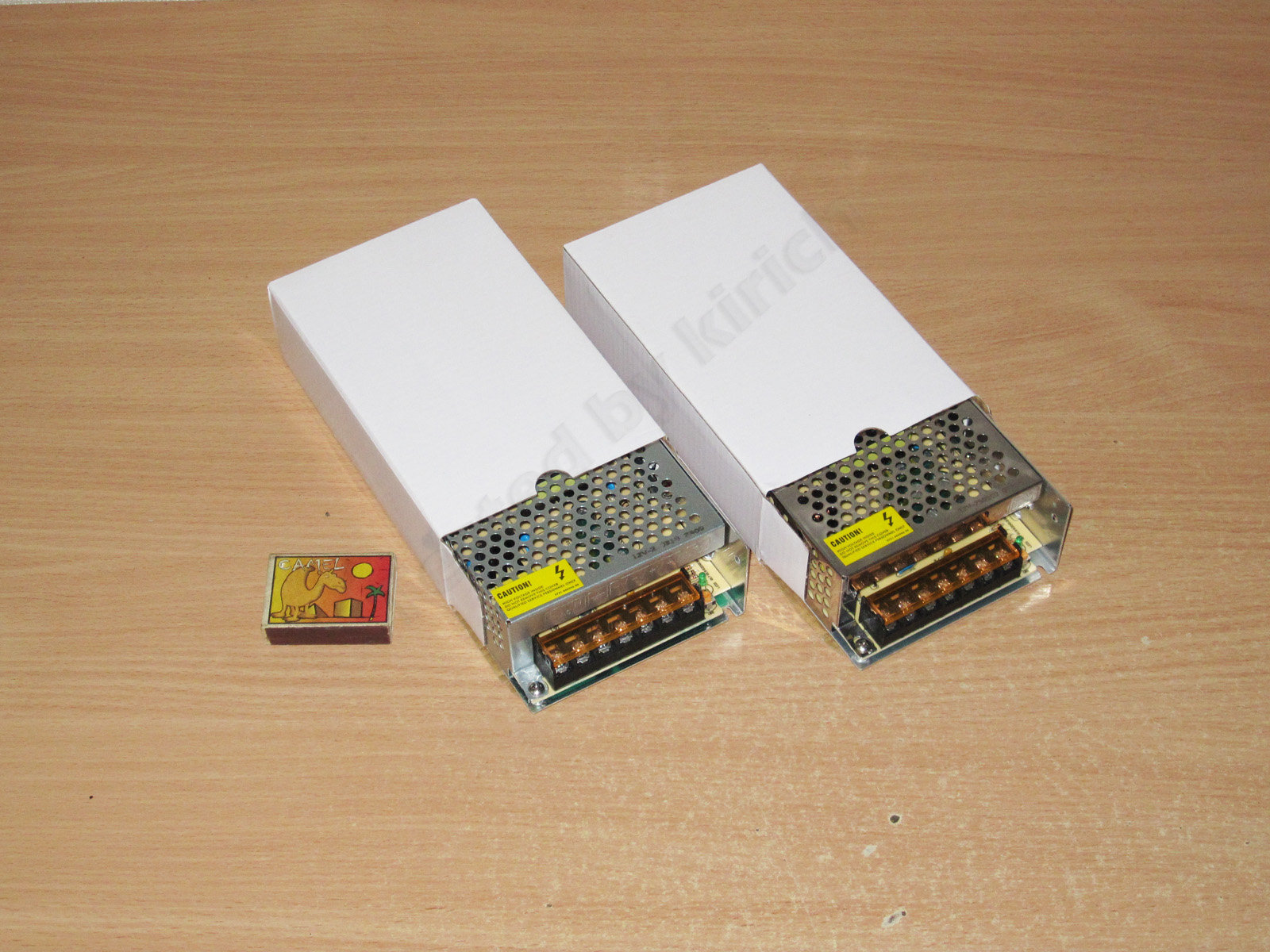
No, I’m not criticizing this design at all. I quite like it, since it offers a very good balance between price and heat dissipation—the enclosure itself acts as a heatsink.
The labels indicate that one power supply is rated at 100 W and the other at 120 W.
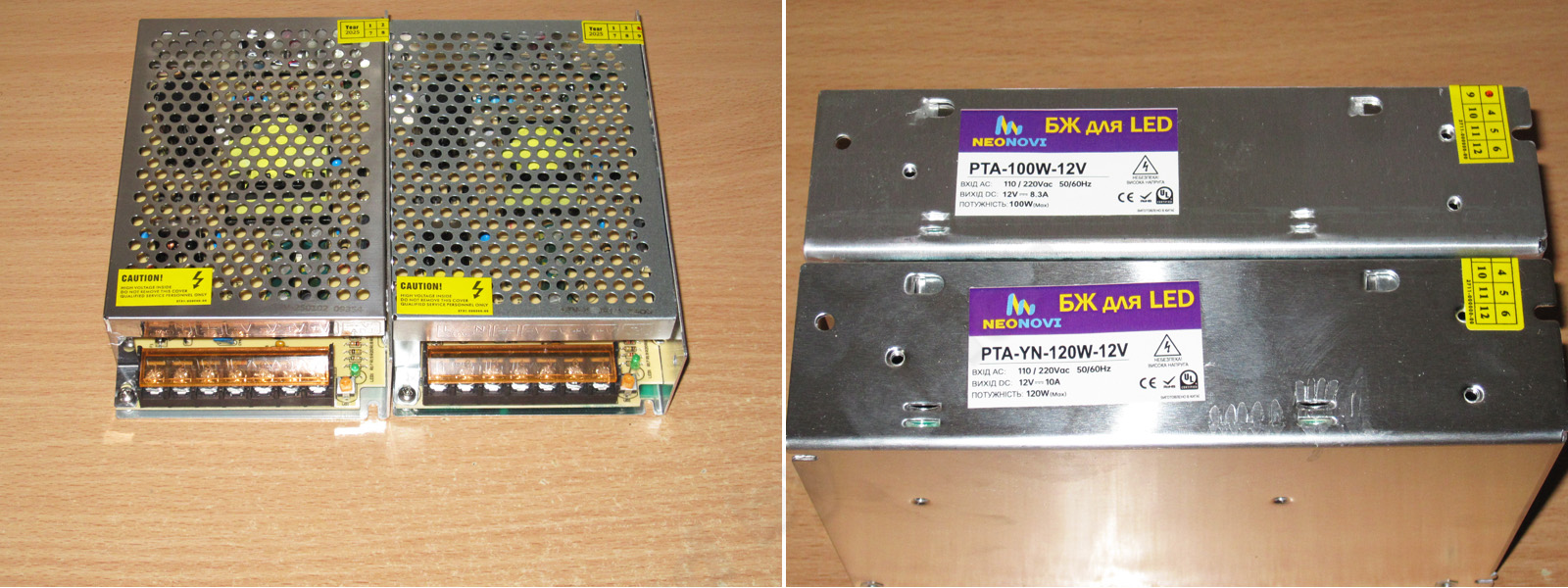
There’s not much to inspect here, so let’s get straight to the internals.
This is a classic single-switch flyback converter, a perfectly suitable and reliable design for the rated power.
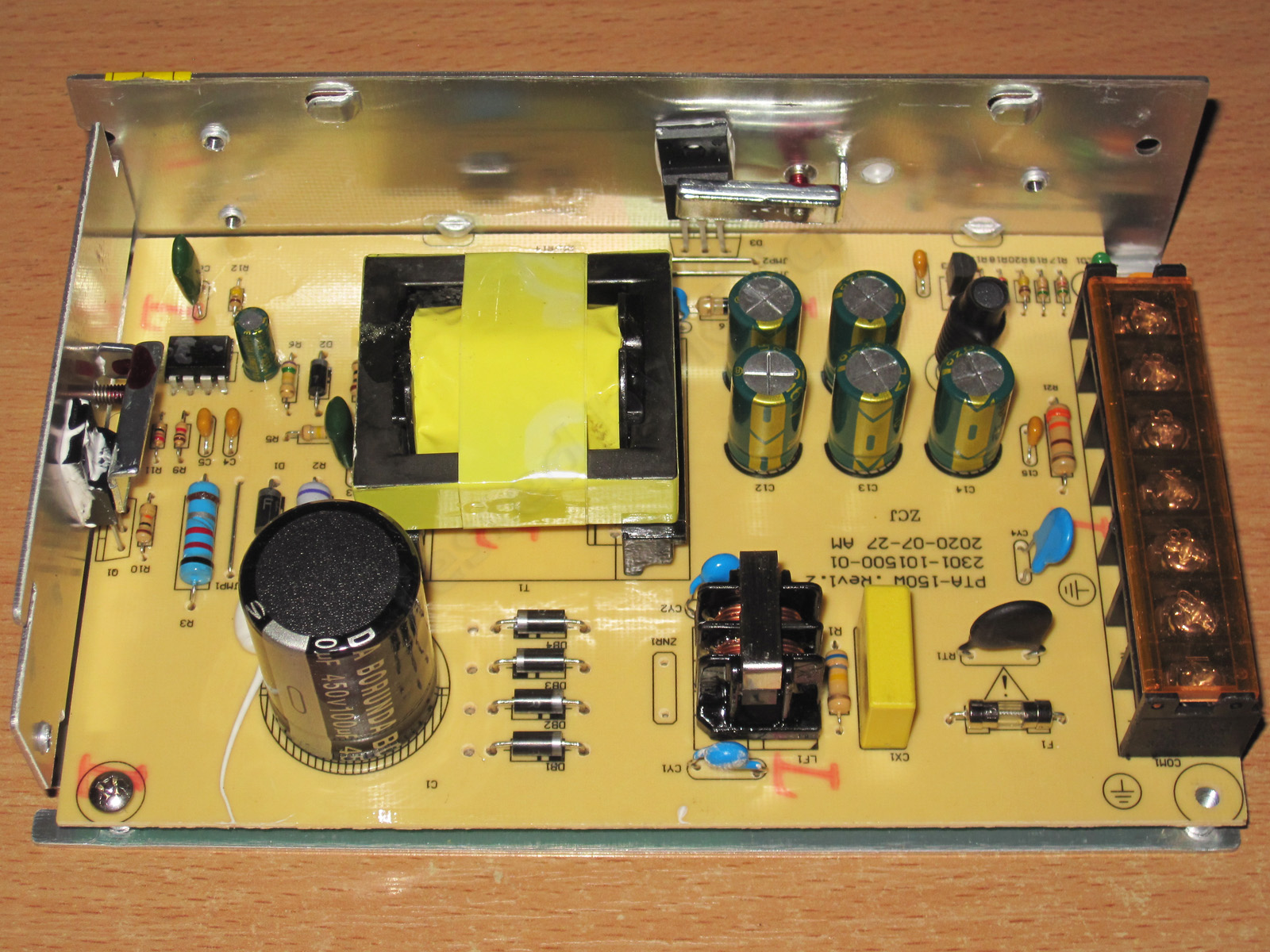
Here we have:
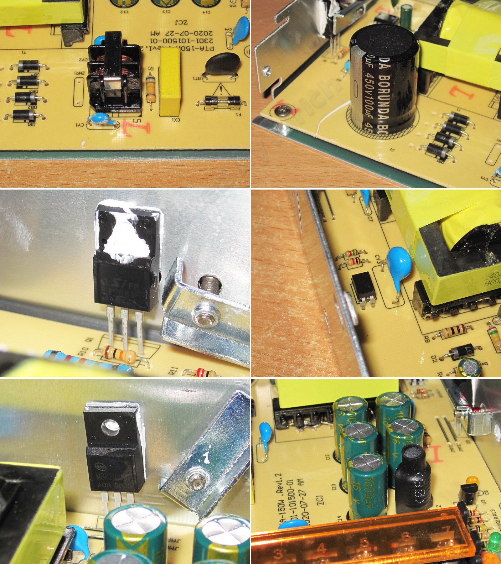
1. An almost complete input filter. The only thing missing is probably a varistor, though there’s room for one.
2. The input capacitor is rated at 100 µF, 450 V. No complaints here either: the capacitance is quite sufficient for our mains voltage, but a little low for 115 V.
3. A 7N65 high-voltage transistor, i.e. 7 A, 650 V.
4. A properly rated Y capacitor, no complaints.
5. A 20 A, 100 V output diode assembly. A little undersized for an output current of almost 9 A, but I don’t think it’s a major issue in this case.
6. There are five output capacitors, each rated at 1000 µF, 16 V. Using 16 V capacitors is perfectly reasonable here (though 25 V ones would be welcome), since there are plenty of them, which reduces the load on each one. And a big plus for the output inductor: it should reduce ripple.
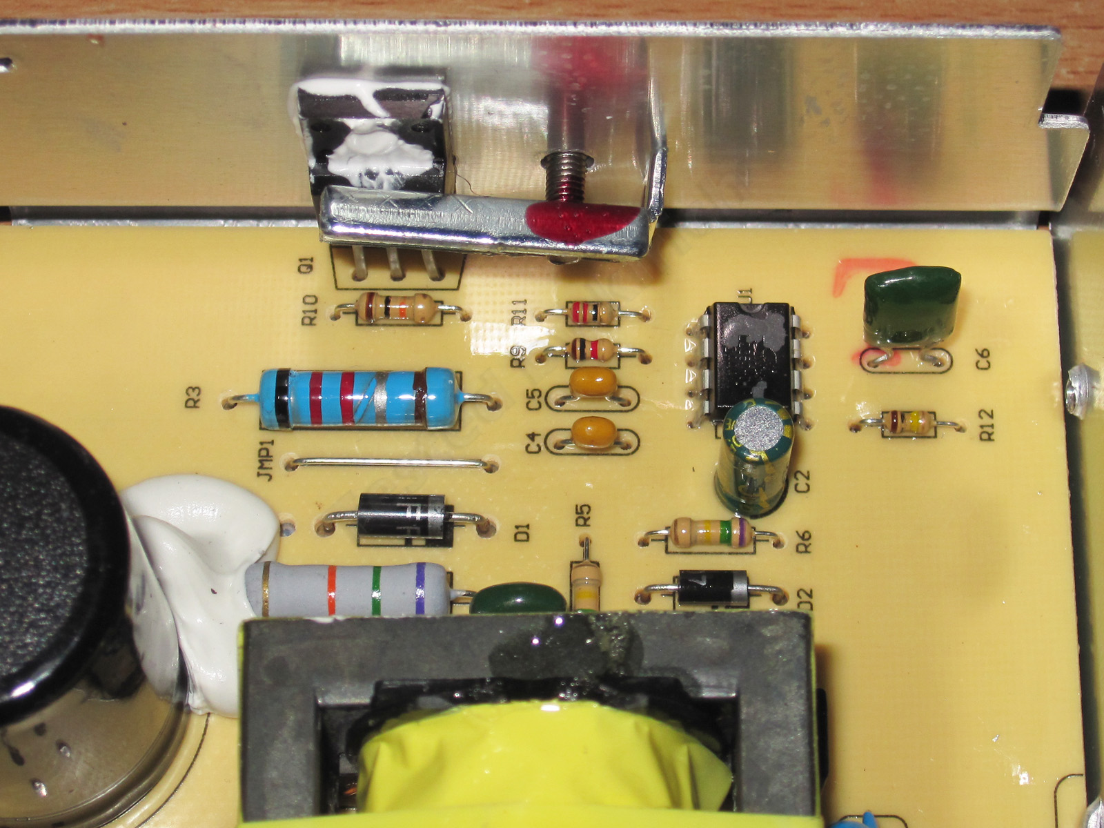
The PWM controller section. Nothing unusual here. What I wanted to point out is that the board is coated with protective varnish, which is especially noticeable around the PWM controller.
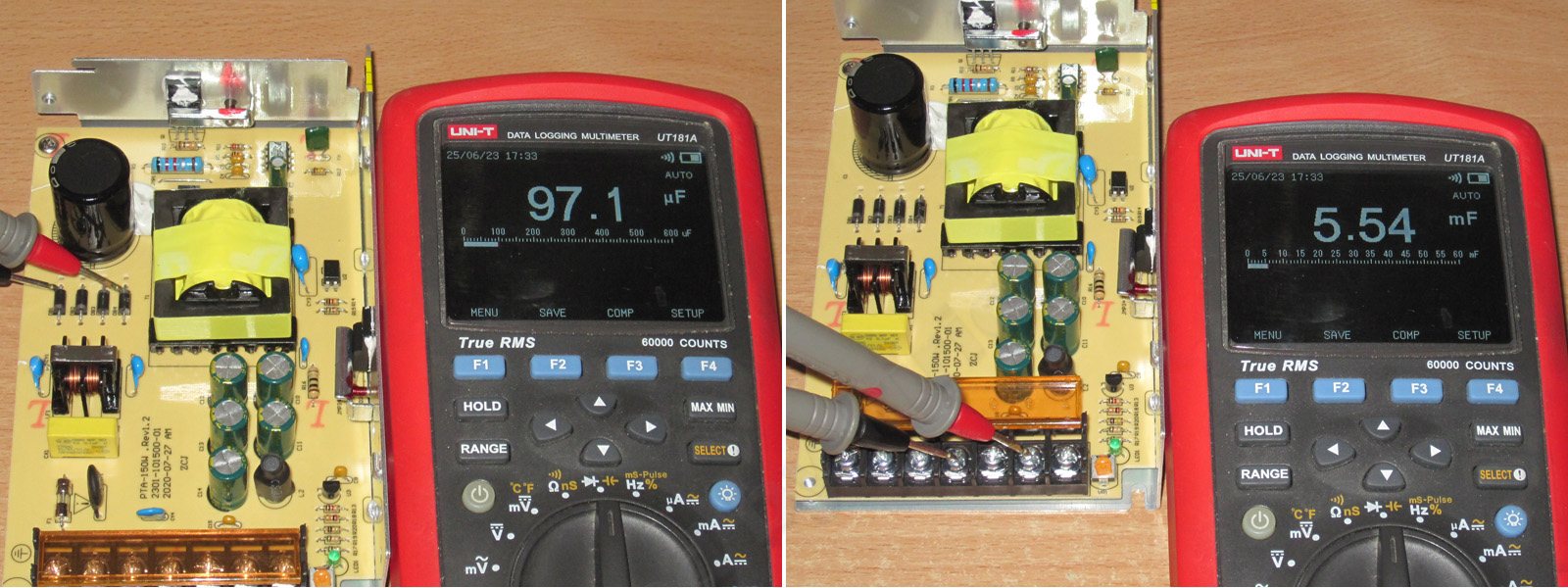
The input capacitor’s measured capacitance was a surprise: 97 µF against a rated 100 µF. They can get it right when they want to.
The output capacitors are usually fine, and these are no exception: 5500 µF against a calculated 5000 µF.
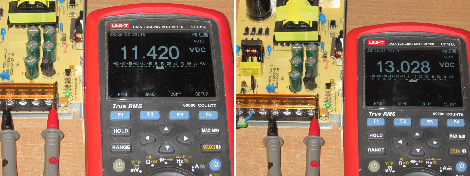
The adjustment range is a bit narrow, just 11.4 to 13 V, though the adjustment is smooth, of course.
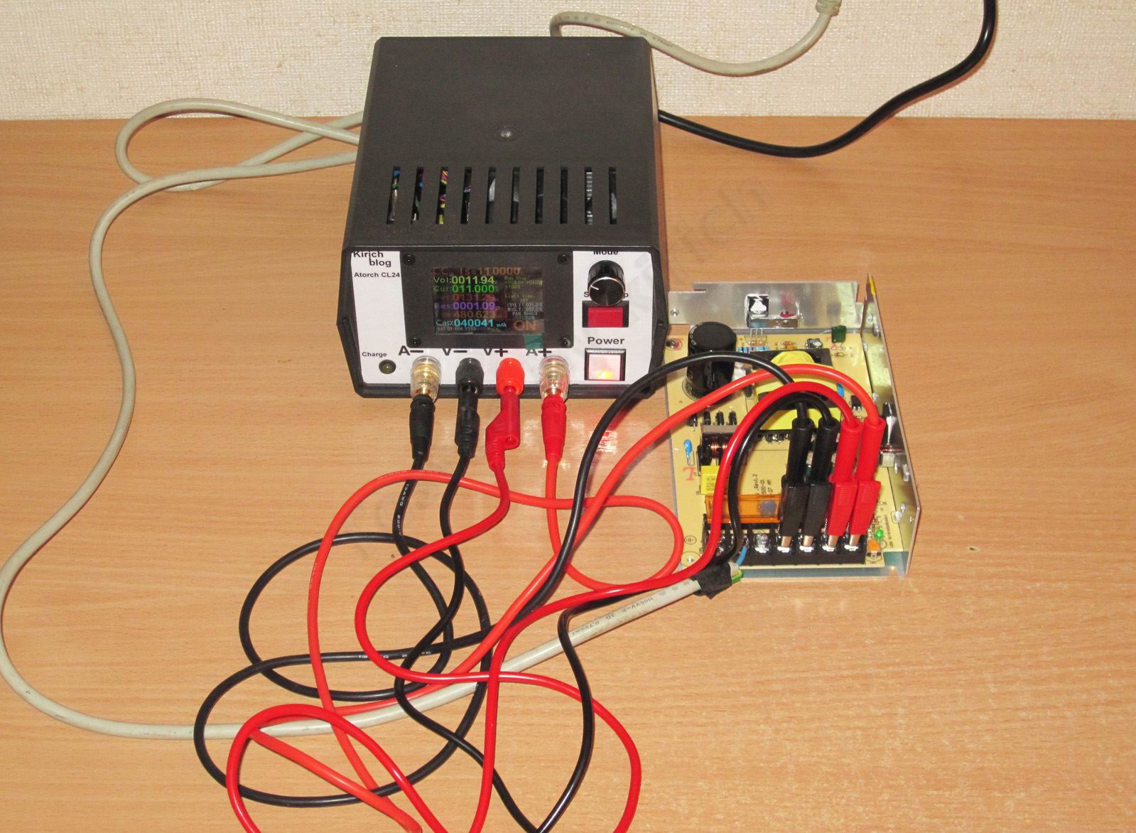
I didn’t connect a multimeter; I just used the electronic load’s own measurements with a four-wire connection. It’s simpler, and the accuracy is more than adequate.
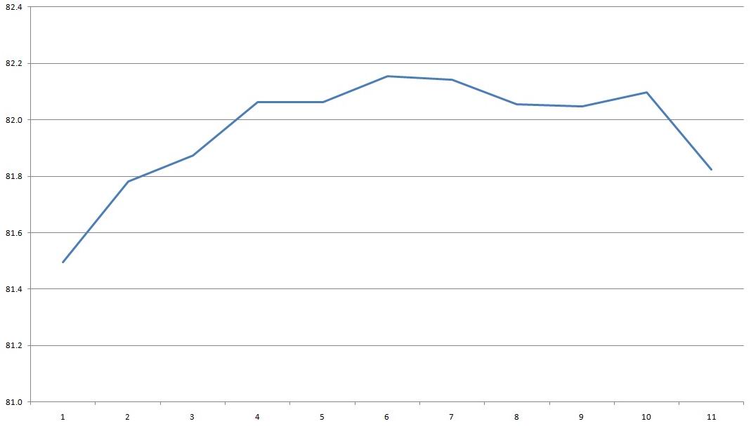
As usual, let’s start with efficiency. It’s hard to call this a proper measurement, but it’s good enough for an estimate. We get a fairly typical 82% here. I’d like to see more, but that’s what we’ve got.
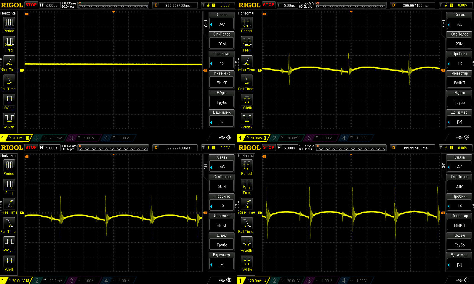
The ripple is really impressive, though. The oscilloscope is set to 20 mV per division. I checked with no load and at currents of 3, 6, and 9 A.
Even at the maximum 9 A, I got about 70 mV, which is less than one percent.
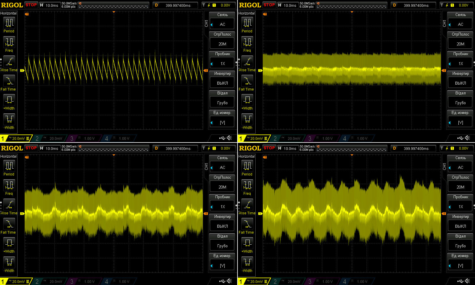
At first glance, the low-frequency ripple looks worse, but it’s fine too. There’s a little 100 Hz ripple at maximum power, but its amplitude is quite acceptable.
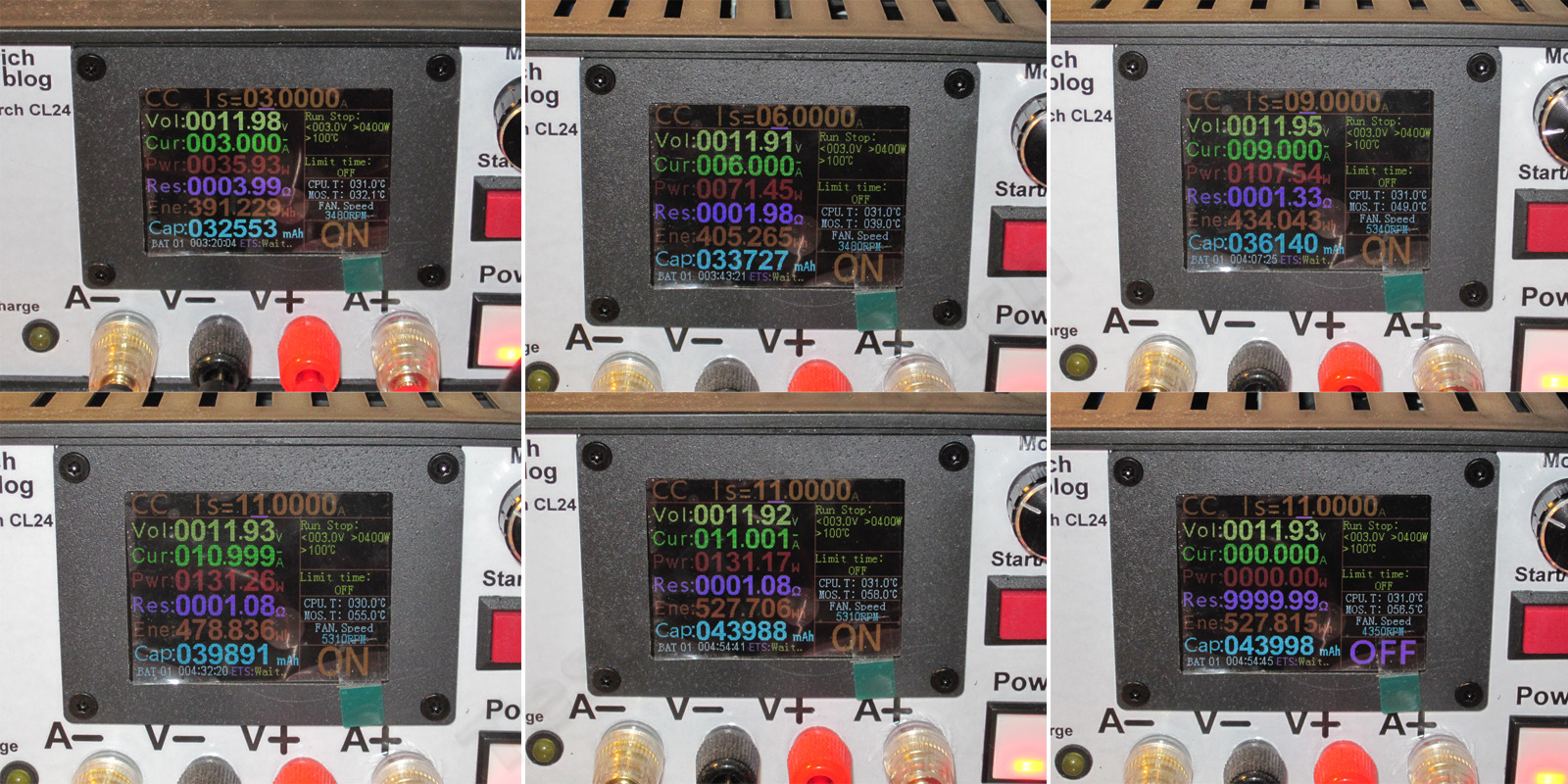
I started the load test at 3, 6, and 9 A (the rated maximum is 8.3 A). Since the power supply performed well, I also ran an additional test at 11 A.
The protection kicked in at a little over 11 A. I didn’t measure it precisely, but let’s say it was around 11.5 A, which is perfectly normal.
With no load, the voltage was 12.98 V.
1. Cold power supply, load current 3 A, voltage 12.98 V; after warming up, it was 12.94 V.
2. Warm power supply, load current 6 A, voltage 12.91 V. This surprised me a little, but after warming up it was 11.96 V.
3. Already hot, load current 9 A, voltage 11.95 V; after warming up, it was 11.94 V.
4. Noticeably hot, load current 11 A, voltage 11.93 V.
5. After warming up under an 11 A load, the voltage was 11.92 V.
6. After removing the load while the power supply was hot, the voltage was 11.93 V.
The output voltage depends slightly on temperature: as it warmed up, the voltage dropped by about 50 mV. There’s also a small dependence on load, but it can be ignored. What surprised me more was that the voltage drops both as the unit heats up and under load. But as you can see above, some tests showed the opposite—for example, at 6 A. I don't know why; I'll have to look into it.
Overall, though, the stability is perfectly acceptable. I have no complaints here.
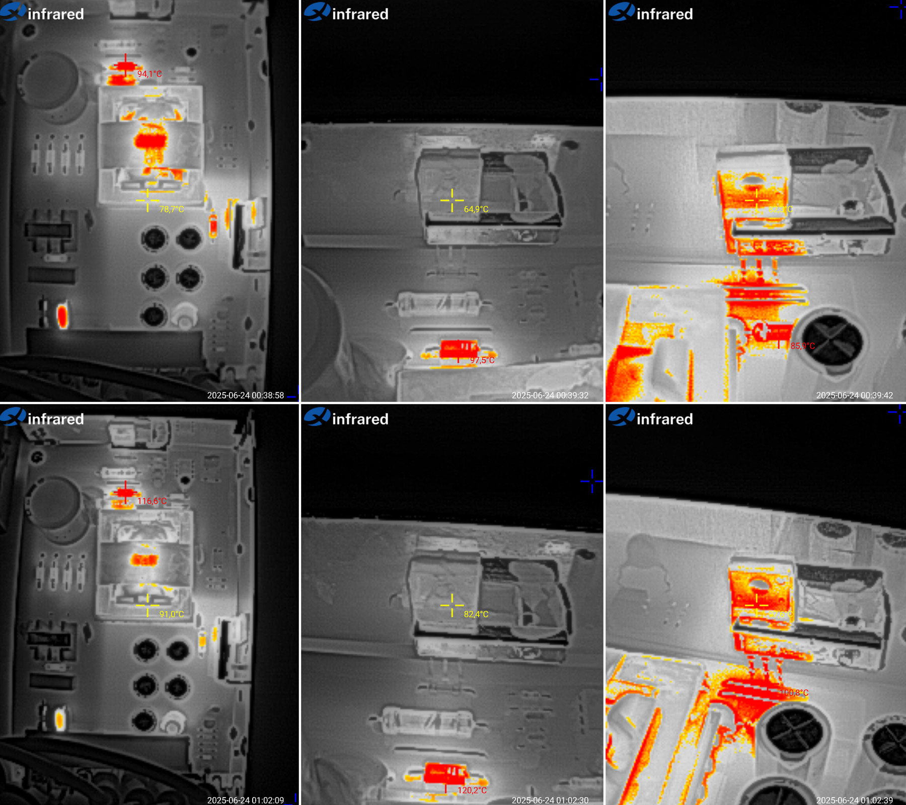
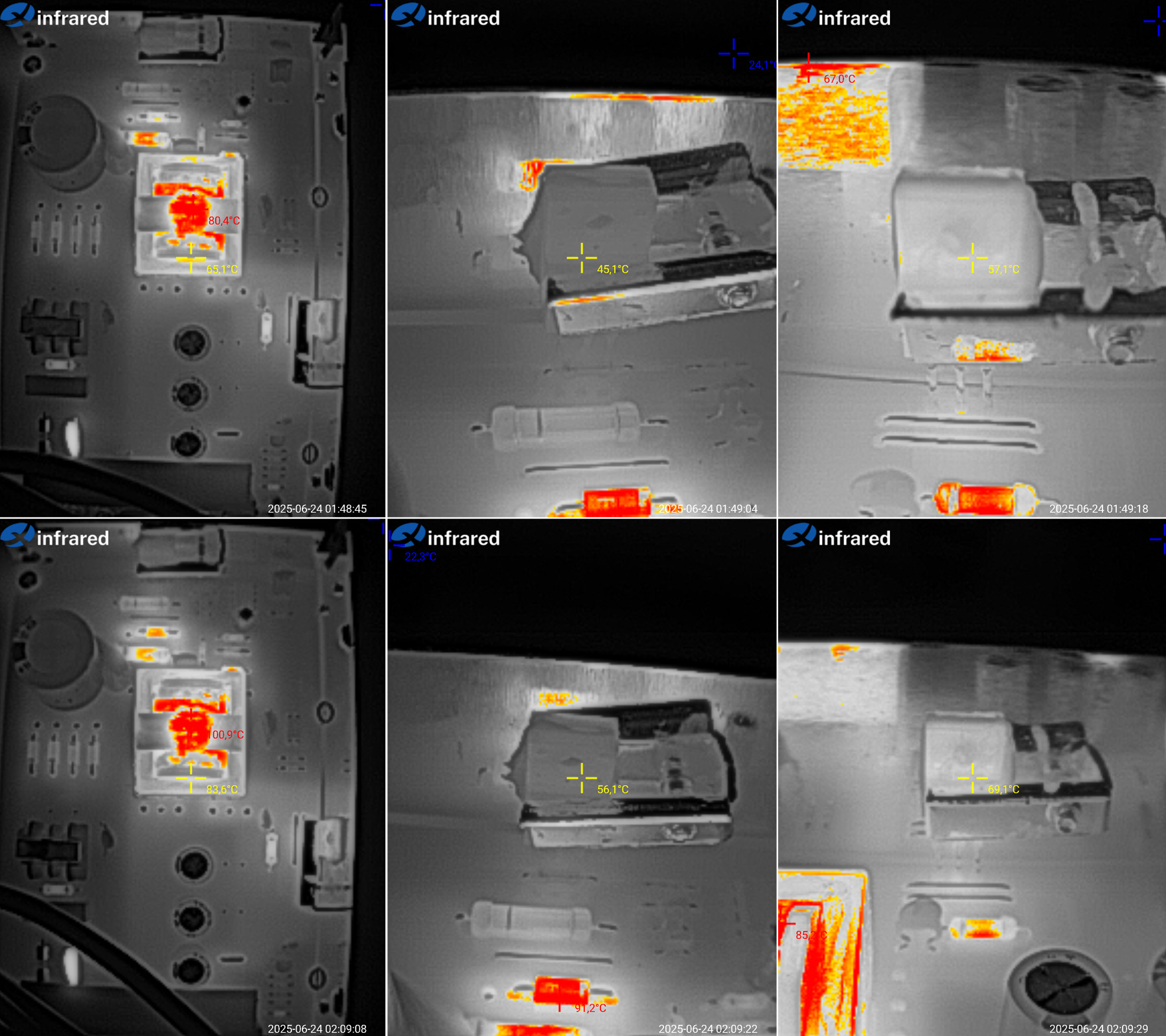
I measured the temperature in every mode, but I think it's worth showing only the results at 9 and 11 A.
At 9 A, the transformer was almost 80 degrees, the high-voltage transistor was 65 degrees, and the output diode assembly was 82 degrees.
At 11 A, the transformer was 91 degrees (measured on the core near the winding), the transistor was 82 degrees, and the diode assembly was 98 degrees.
In my opinion, these are excellent results. The power supply has plenty of headroom, even when operating close to the overload protection trip point. So, of course, you can burn this power supply out, but it would be quite difficult: at 11 A it doesn't overheat, and at a slightly higher current the protection kicks in. It would be even better if the manufacturer had also included overtemperature protection.
The person who sent me these power supplies also asked me to check how they work with a 115 V input. Well, let's take a look. Lower input voltage usually affects the temperature of the input transistor; the temperatures of the other components don't change much.
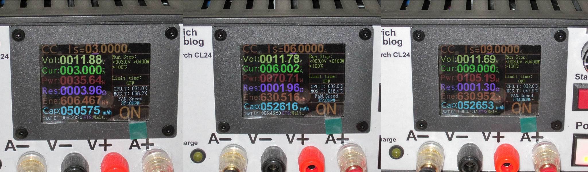
I tested it at 3, 6, and 9 A. The connection was two-wire, so don't pay too much attention to the voltage readings. At a higher current, close to 9.5 A, the protection kicked in.
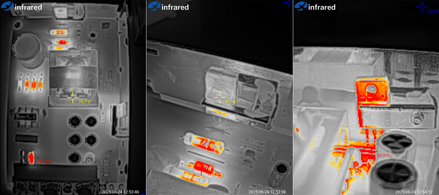
Results after warm-up at 9 A.
The transformer was around 80 degrees, the transistor was 87 degrees, and the diode assembly was 90.8 degrees. I can say the results are excellent here too. The power supply is rated for an 8.3 A load; at 115 V, the protection trips at around 9.5 A, but the unit doesn't overheat.
Again, the results are excellent: the power supply either operates within a normal temperature range or the protection kicks in. In this case, the protection trips at a current slightly above the rated maximum. Five stars for this one.
The second power supply is also rated for 12 V, but this one is rated at 120 W, with a maximum current of 10 A. Inside, it looks suspiciously similar to the previous one.
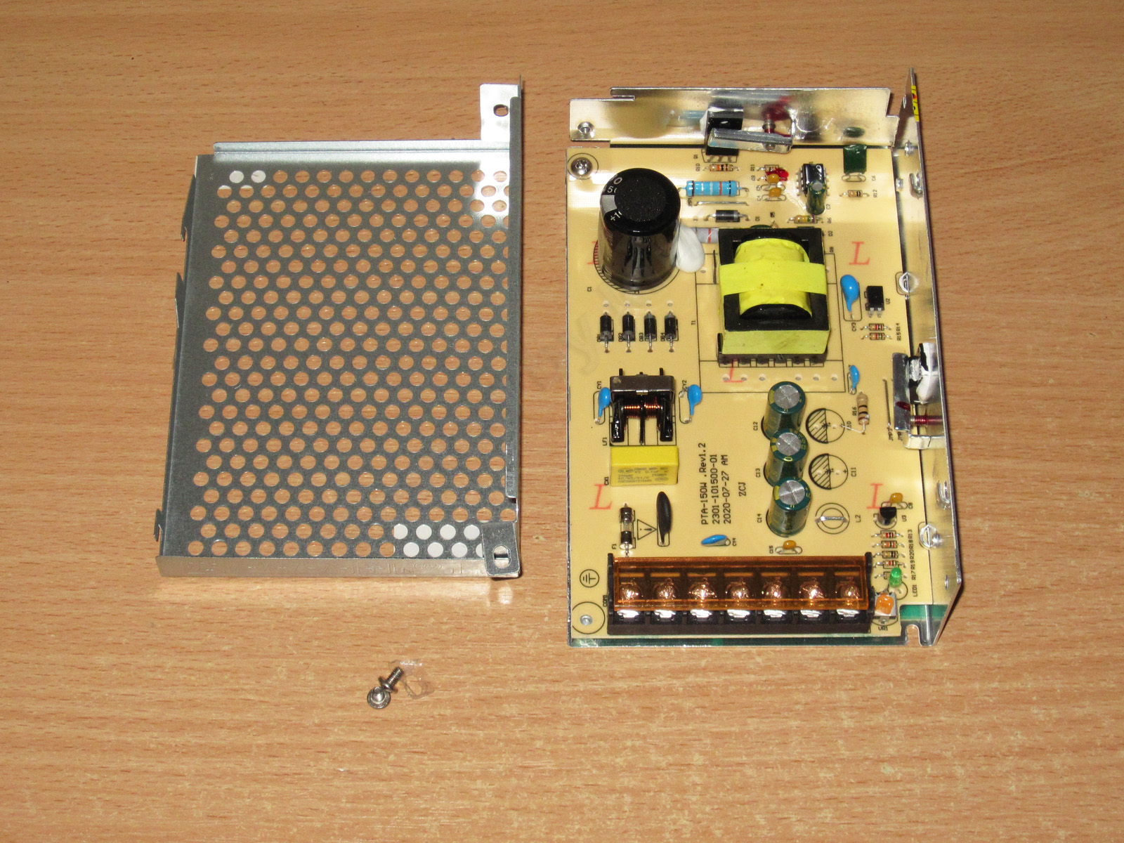
No wonder it looks similar: both power supplies are built on the same circuit board, which is completely identical.
At a glance, the differences are that the 120 W version has a slightly smaller transformer, three output capacitors instead of five, and no inductor.
There are probably some minor differences in resistor values too, but more on that later.
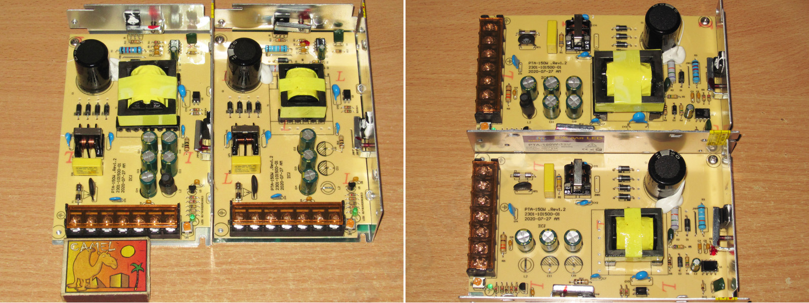
1. Input filter, identical to the previous model.
2. Input capacitor, identical to the previous model.
3. PWM controller section. It looks the same, but the current-sense resistor is clearly a different value, as you can tell from the marking.
4. 5N65 transistor, rated for 5 A and 650 V; the previous model had a 7 A transistor.
5. Diode assembly, rated for the same 20 A and 100 V as the previous model.
6. As I mentioned, there are three capacitors instead of five. The capacitors themselves are the same, 1000 µF, 16 V. More on those later.
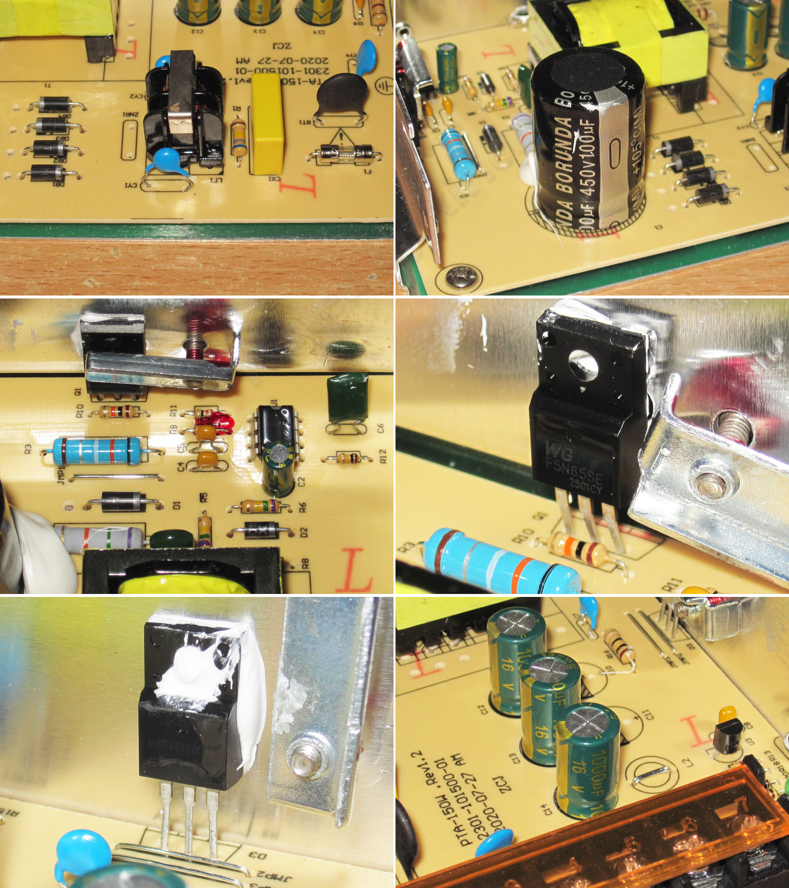
The transformers are different too, although they look identical at first glance.
The 100 W version is on the left, the 120 W version on the right. You can see that the circuit board is universal, designed to accommodate two transformer sizes.
The core dimensions are:
100 W - 42x37x11 mm
120 W - 33x30x11 mm.
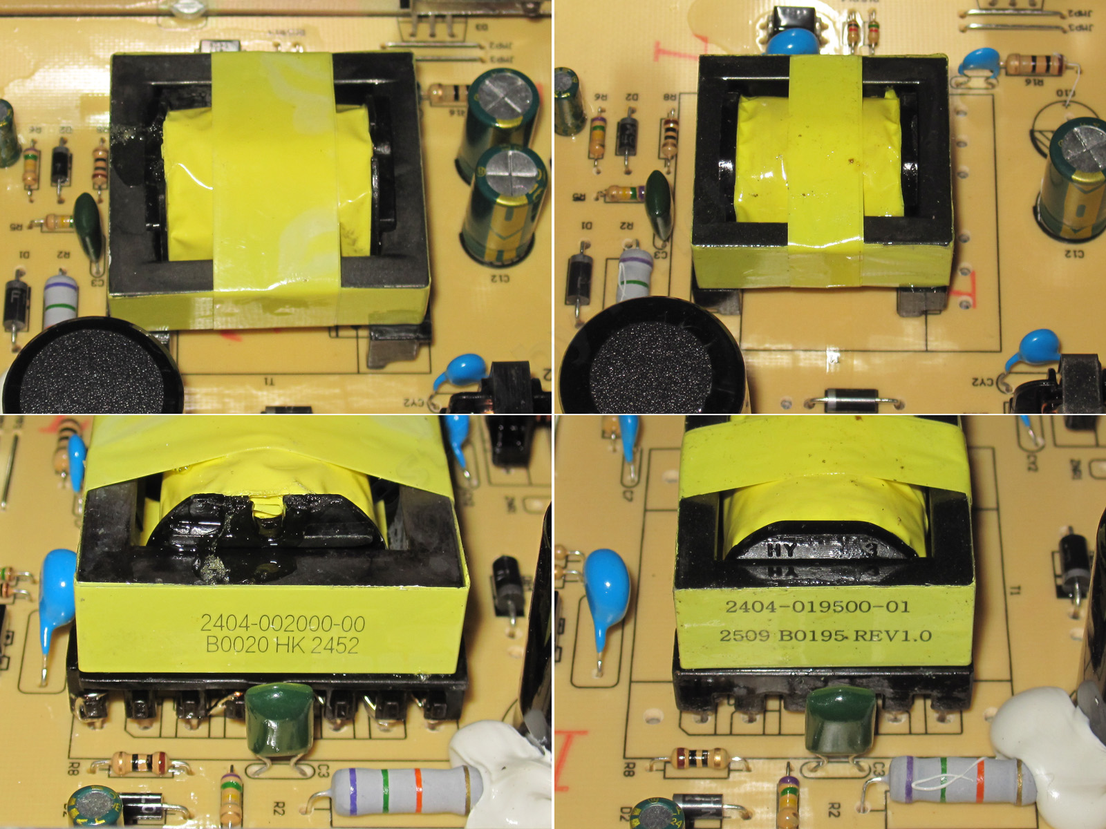
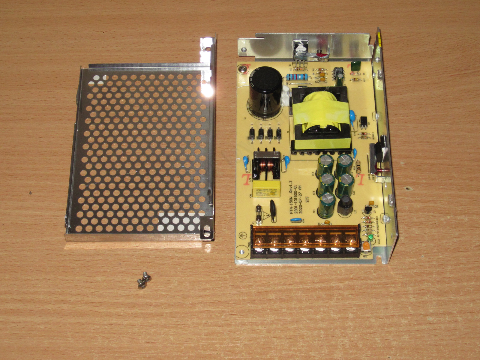
Since we've already established that the circuit boards are identical, I only took apart one power supply, after all the tests were done. And, as you may have guessed, it was the 120 W model.
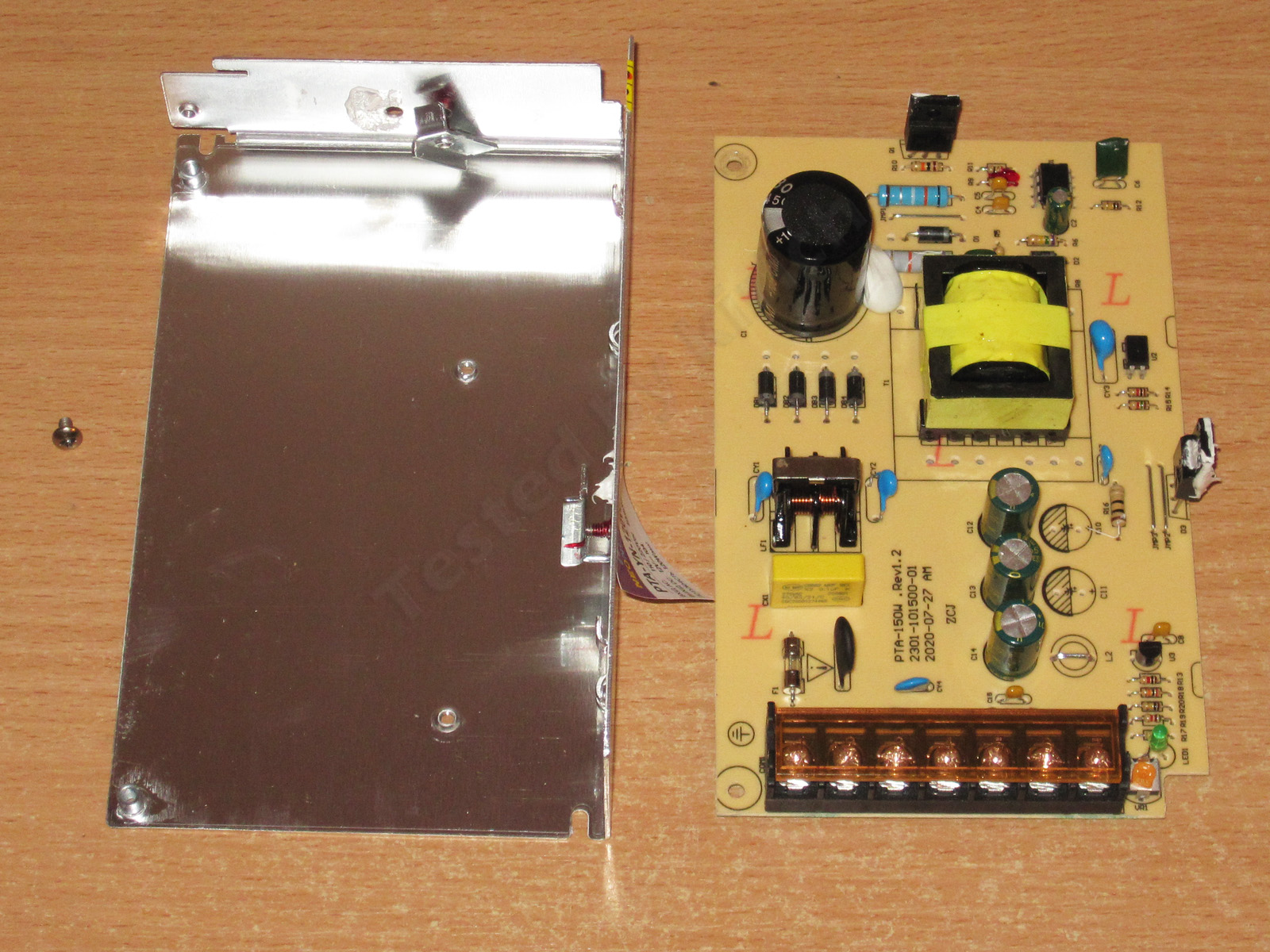
The circuit board out of the case. By the way, according to the markings, the board is designed for models up to 150 W.
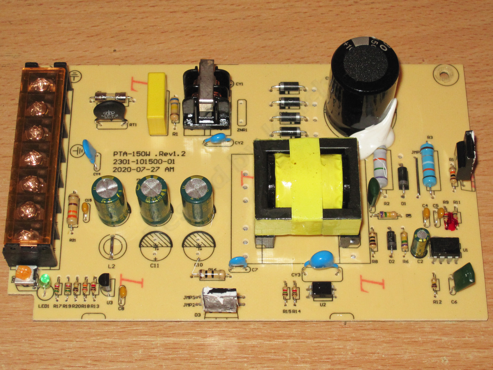
I have no complaints about the circuit board. Yes, there are no slots here, but the clearances themselves are sufficient. Plus, don't forget that this type of power supply must be grounded. Unfortunately, not everyone does that.
A note on safety, and this applies to both models. The board has a capacitor marked CY4 near the terminal block. It's labeled as a Y-type capacitor, but it's actually a regular high-voltage capacitor. In this case, it's completely safe because it's connected between ground and the output negative. But even if ground isn't connected, it's still safe, because it will be in series with two Y-type capacitors located near the input inductor.
So, no complaints here either. For those who don't know why a 5000 V high-voltage capacitor is a bad choice, while a 400 V Y capacitor is fine. There can be voltage spikes on the mains, for example due to lightning. In that case, a 5 kV capacitor can easily short out, while a 400 V Y capacitor usually won't.
Well, that's how it goes, kids.
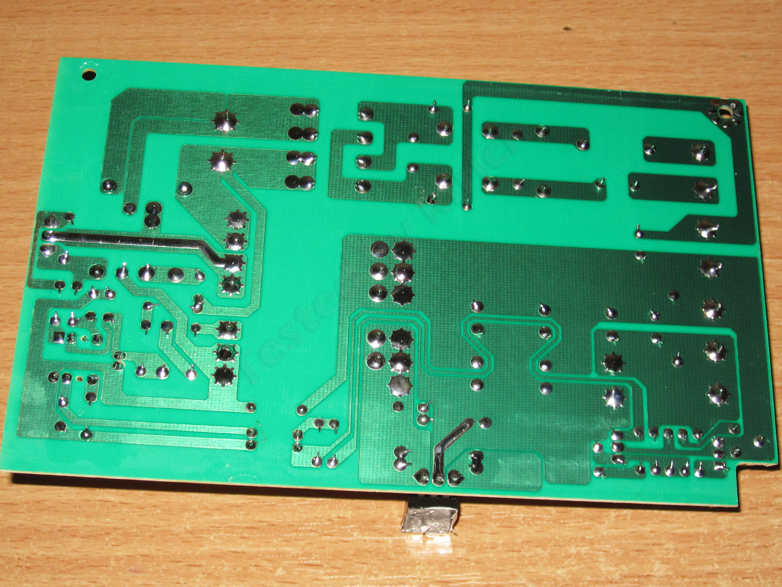
I scraped the coating off the PWM controller, and it turned out to be L2263/
Nothing unusual, really, except that it's available in both 6-pin and 8-pin packages. In the 8-pin package, two pins simply aren't used. They could have added thermal protection on one of them :(
The chip is actually specified to have Internal over temperature protection (OTP), but I couldn't find the trip threshold in the datasheet at a glance. I can already say, though, that it's a bad idea: by the time the chip heats up from the surrounding components, it's usually too late to save anything.
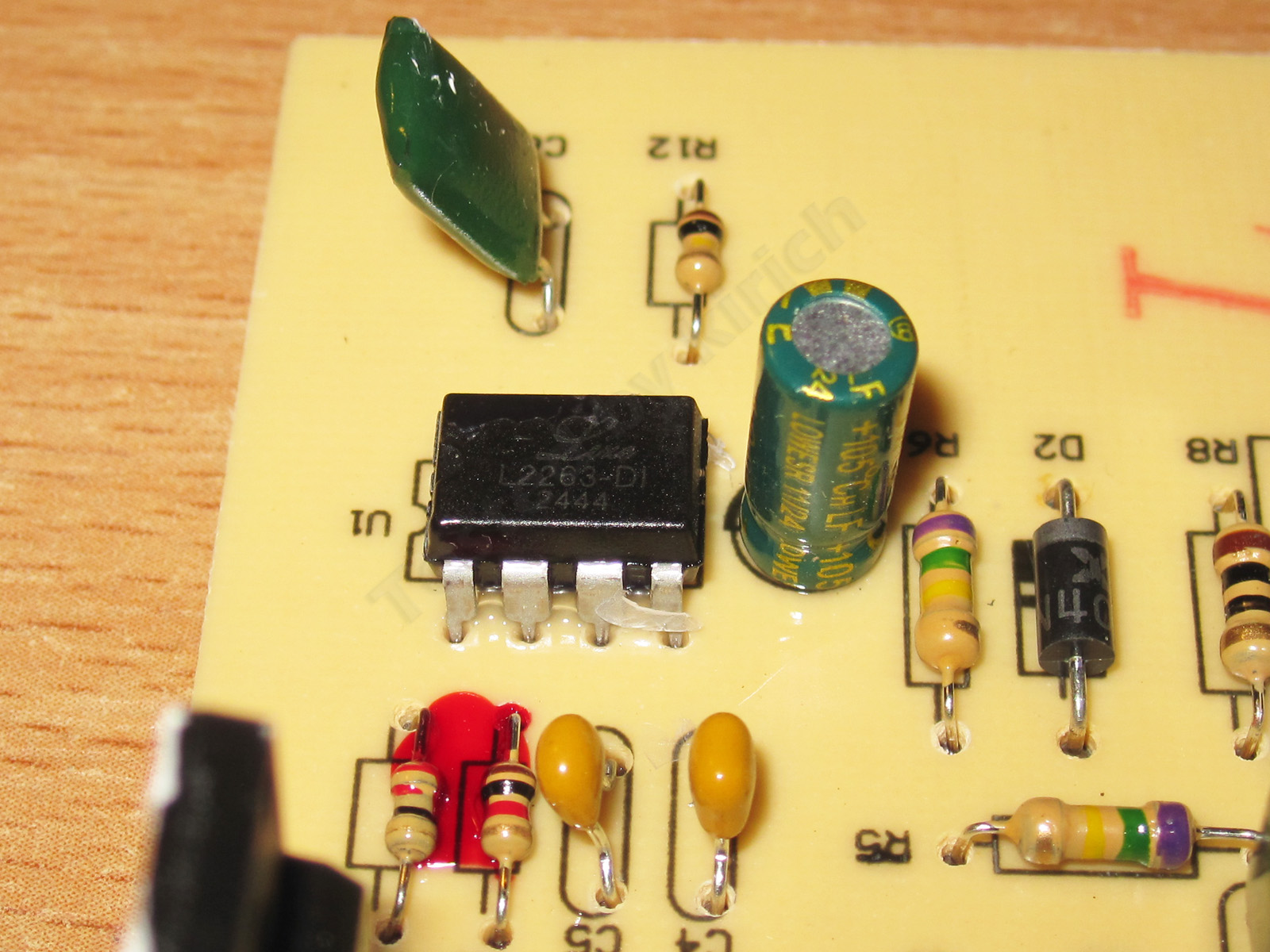
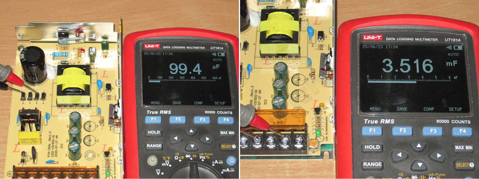
As with the 100 W model, I have no complaints about the capacitors' actual capacitance. The input capacitor measures 99.4 µF against the stated 100 µF, and the output capacitors measure 3500 µF against the calculated 3000 µF.
Sure, 100 µF is a bit tight for 120 W, but let's see how it does.
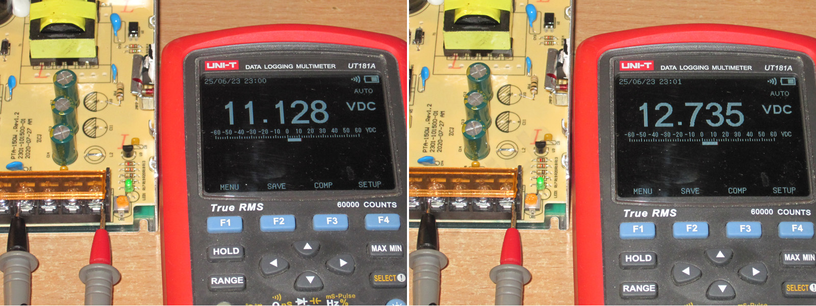
The output voltage adjustment range is 11.1–12.7 V, just as narrow as on the 100 W model, but shifted 0.3 V lower.
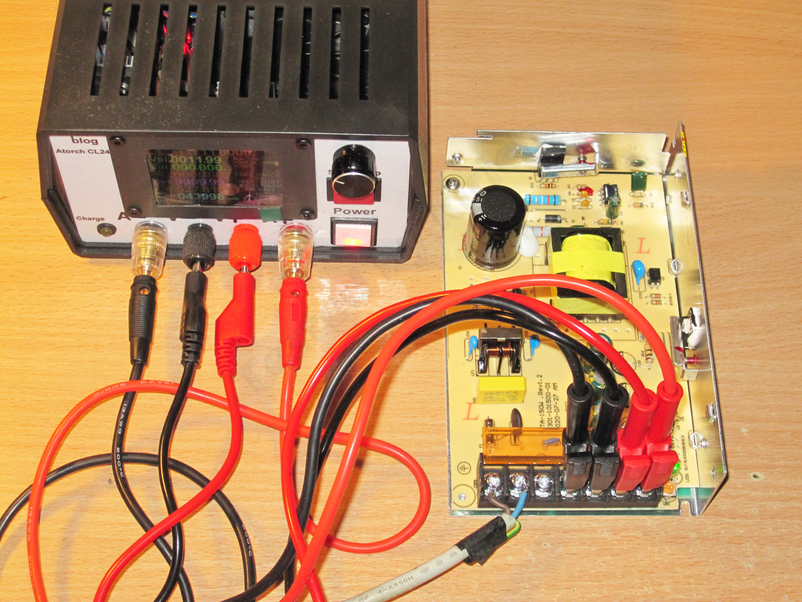
For the tests, we'll use the same four-wire connection as with the previous unit, so as not to "fudge the results."
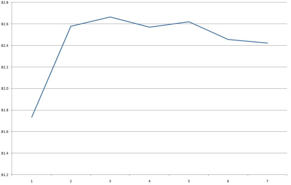
Efficiency is more or less the same as on the 100 W version, but I found a "catch": this unit's overcurrent protection is set just above 7.3 A.
So this isn't a "budget version" of a 100 W power supply; it's an 80–85 W power supply, give or take.
And I have to say, that's much better than if the manufacturer had downgraded the components but set the overcurrent protection to, say, 11 A. Yes, it's misleading, I agree—but it's misleading about the stated power rating, and doesn't affect reliability.
I'll also come back to the output capacitors. As I mentioned above, there are three instead of five, but the current is lower too, so they end up operating under the same conditions as in the previous unit. Sure, 25 V capacitors would be preferable, but with three small ones instead of one large one, they'll do just fine.
Actually, even during testing I had a strong feeling that the stickers had simply been mixed up: the 100 W model should have had the 120 W sticker (it works fine at 130 W too), and this one should have been labeled 100 W. But the truth turned out to be much more mundane: if I understood correctly, the 120 W model costs less than the 100 W one.
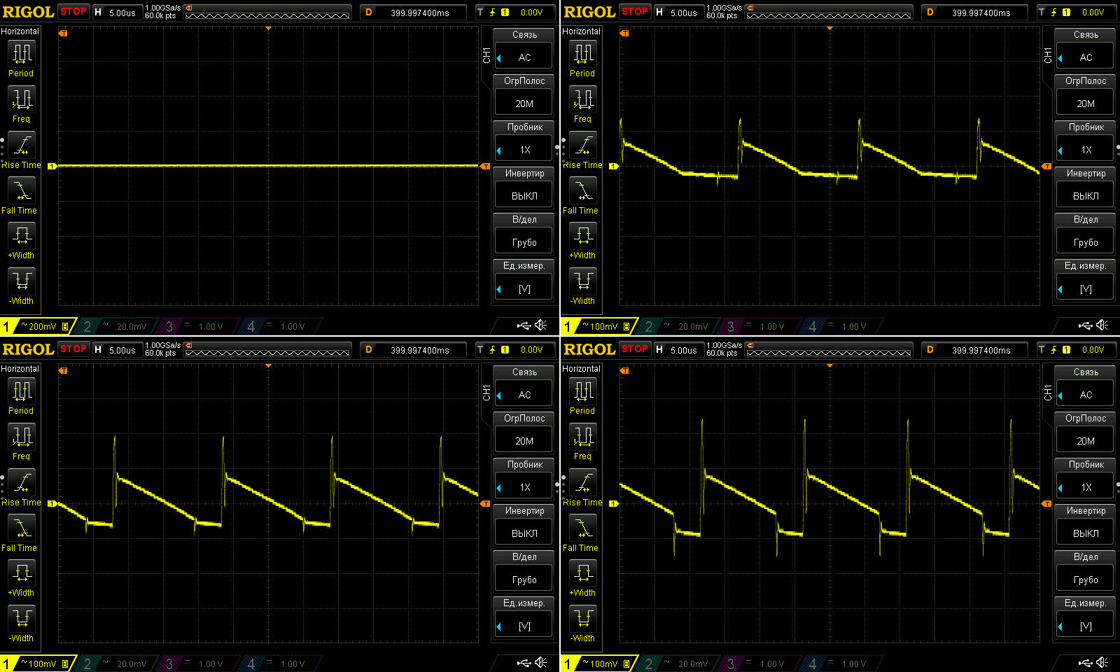
The ripple results are predictable: there's no output filter, so of course the ripple is going to be high.
I tested with no load and at currents of 2.5, 5, and 7.3 A. At high frequency and maximum power, we get about 400 mV including the spikes, with the main ripple component around 200 mV. That's acceptable, really, thanks to the three 1000 µF capacitors on the output.
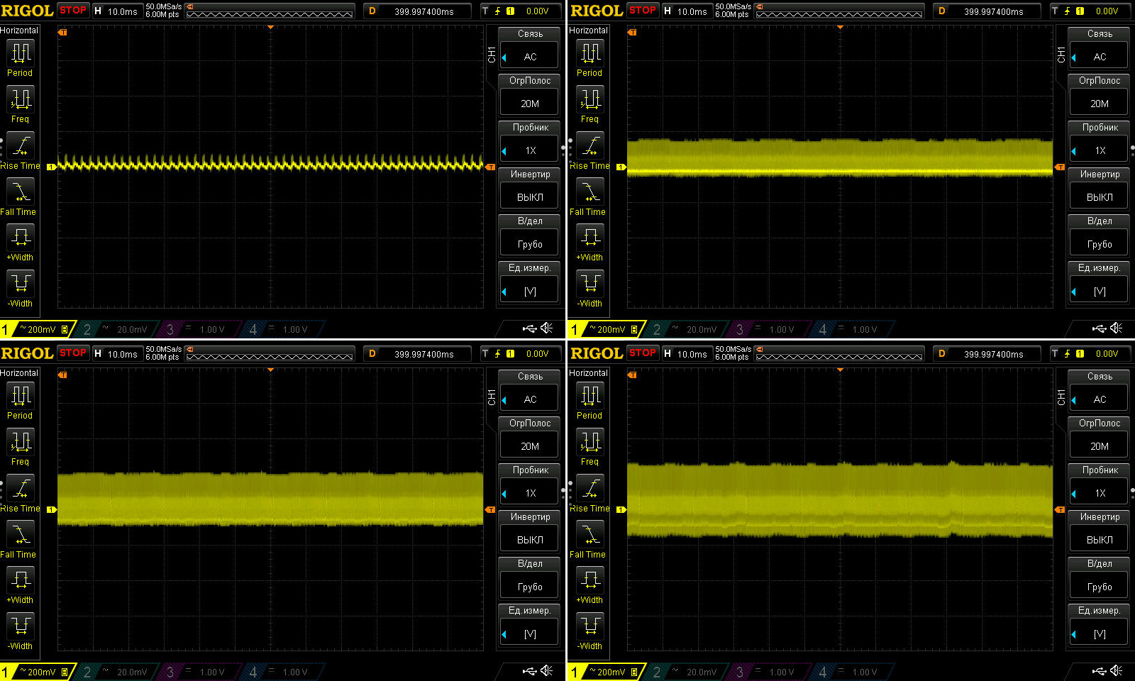
At low frequency, the 100 Hz ripple is actually lower than on the previous unit, which makes sense: both power supplies have a 100 µF input capacitor, but I tested the previous one at 9 A and this one at 7.3 A. The overall ripple is of course higher because of the high-frequency component.
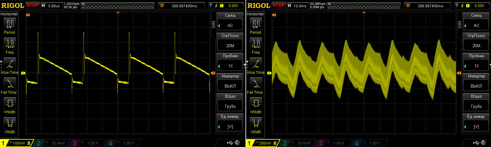
And here's what the output looks like as we approach the protection trip point. The results above were at 7.3 A; this is at 7.5 A.
At high frequency, there's no visible change, but at low frequency the unit starts to "go haywire." Raise the current just a little more, to 7.6 A, and the protection trips.
It's neither good nor bad; I just happened to notice it and thought I'd show you.
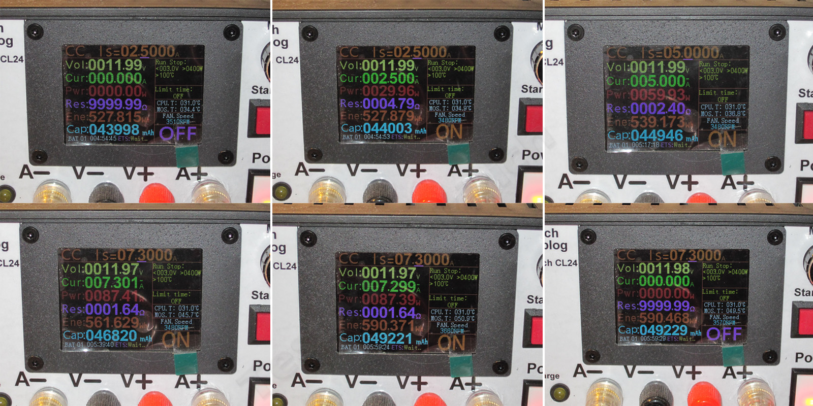
Load test:
1. No load, cold unit: 11.99 V.
2. At 2.5 A, cold unit: still 11.99 V.
3. Warm unit at 5 A: no change, still 11.99 V. After testing the previous unit, this almost seems suspiciously good.
4. Warmed-up unit at 7.3 A: the voltage dropped slightly to 11.97 V.
5. Fully hot unit at 7.3 A: still 11.97 V.
6. After removing the load, hot unit: 11.98 V.
The output voltage stability here is genuinely excellent. It's even surprising that the previous unit's voltage varied over a noticeably wider range. My guess is that its trimmer potentiometer drifted a little.
Component temperatures at 5 and 7.3 A.
5 A: transformer 65 °C, transistor 45 °C, output diode assembly 57 °C.
7.3 A: transformer 84 °C, transistor 56 °C, diode assembly 69 °C.
Here I can say without hesitation that the results are very good. If we treat this power supply as an 80–85 W unit, then the protection is set correctly and the temperatures are within normal limits. The person who sent them said they’ll most likely make new labels showing the actual power, so buyers aren’t misled.
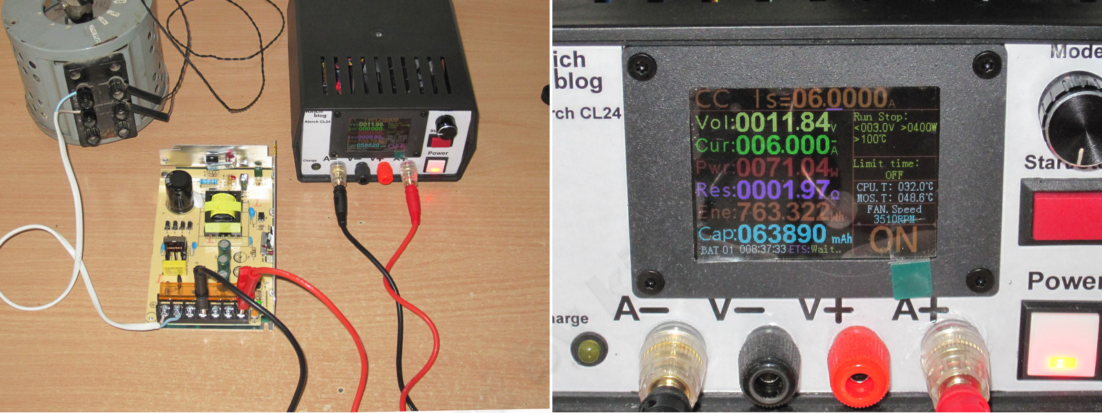
As with the 100 W version, I tested it with an input voltage of 115 V. The test stages were the same: first 2.5 A, then 5 A, and finally the maximum possible. But the results at maximum current are the interesting part. That turned out to be about 6 A; when I increased the current to 6.1 A, the power supply went into protection.
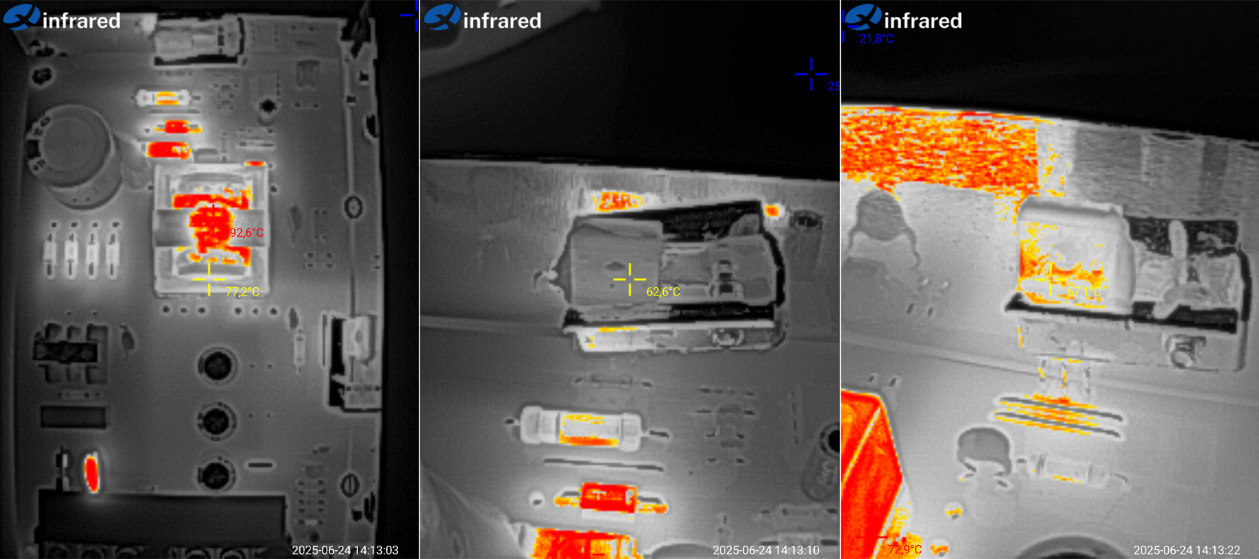
The input voltage was 115 V. Efficiency dropped, of course, and temperatures went up, but the load power was also lower.
The transformer reached 77°C, the transistor 62.6°C, and the rectifier diode assembly 67°C.
So the temperatures are well within safe limits, meaning it would be quite difficult to overheat this unit.
Conclusions.
100 W model. This is a genuinely good power supply. It’s rated at 100 W (8.3 A), but at 230 V it runs comfortably at 130 W (11 A), and at 115 V it delivers up to 110 W (9 A). Temperatures are fine, there’s an output filter, and the input capacitor is properly rated. So, of course, it’s no Mean Well, but I have to admit this is definitely a decent unit.
120 W. This one is a different story: the manufacturer’s 120 W rating is clearly misleading. But if you consider it an 80–85 W model at 230 V, or a 70 W model at 115 V, it’s quite decent. My only real complaint is the lack of an output inductor.
Temperatures are fine, the protection works, and yes, the ripple is noticeably higher—but what did you expect when there’s no output filter?
Both units are assembled very neatly, and I have no major complaints about the components either. The PCB layout raises no safety concerns.
In short, both models are perfectly decent: the 100 W model is simply a good power supply, while the 120 W one is a decent 80 W power supply :)
That’s all for today. I hope this was useful, and thanks to Vitaly for providing the samples. What do you think of these power supplies?
обратноходовый блок 100 ватт
Questions and answers
How much power can the 100 W power supply handle?
At a 230 V input, it operated at 11 A, or about 130 W. At 115 V, it delivered up to 9 A, around 110 W.
Does the 120 W power supply really deliver 120 W?
No. The author says its rating is overstated and considers it a roughly 80–85 W unit at 230 V, or 70 W at 115 V.
What is the ripple on the 100 W power supply?
At a 9 A load, the author measured about 70 mV. The output voltage changed only slightly with heating and load.
This model is included in the summary table: Comparison of power supplies: ripple, efficiency, and temperature rise
The figures from this review are in the measurement database: Power supplies
Discounted products
You may be interested in



Discounted products
All the content on the site and the advice are free, but we’d be grateful for your support of the project and the channel!
Comments1
Only registered readers can comment. It takes a minute to sign up, and you can log in with the same account you use on the forum.
Log inRegister
Comments are published in their original language.