
Six 12 V stick-style power supplies rated from 18 to 72 W
A reminder: to keep up with new posts on the blog, I recommend following me on Instagram. I’ll post notifications about every new article there, and might also write about something interesting from time to time — link to my account
You can also subscribe to updates and new articles on the Telegram channel — https://t.me/KirichBlog Note that discussions of reviews and articles are enabled on the channel, along with general chat. I recommend it.
Somehow, at my suggestion, we ended up calling power supplies in this form factor “sticks,” since they clearly stand out even among ultra-slim models. These supplies do have a specific niche: things like thin LED advertising signs.
In this review, I’ll criticize some models for their electrical safety, so let me explain. In principle, these supplies can still be used, provided the product they’re installed in is made of insulating material or is reliably grounded, and all work is carried out by qualified personnel. Still, I try to point out what’s safe and what needs careful attention.
I should also mention that these models arrived without potting, though I can well imagine that potted versions are also available, which would greatly improve electrical safety. But today I’ll treat these as unpotted power supplies and assess them accordingly.
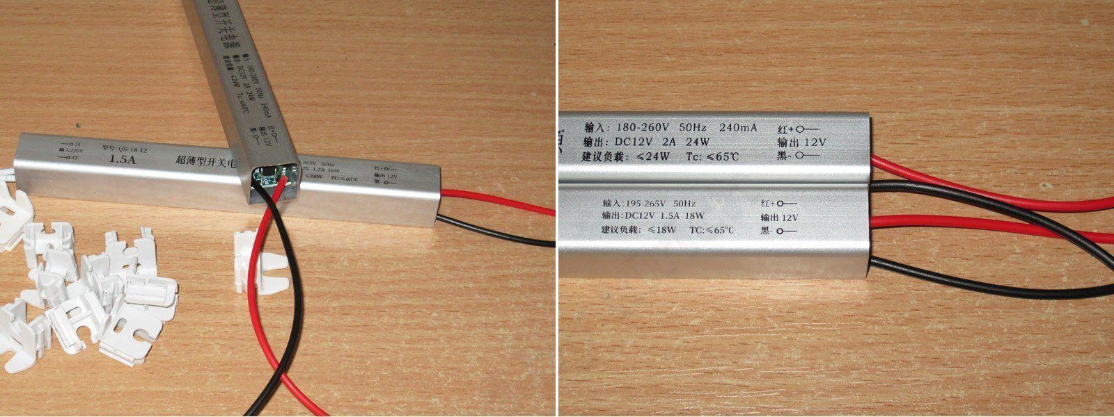
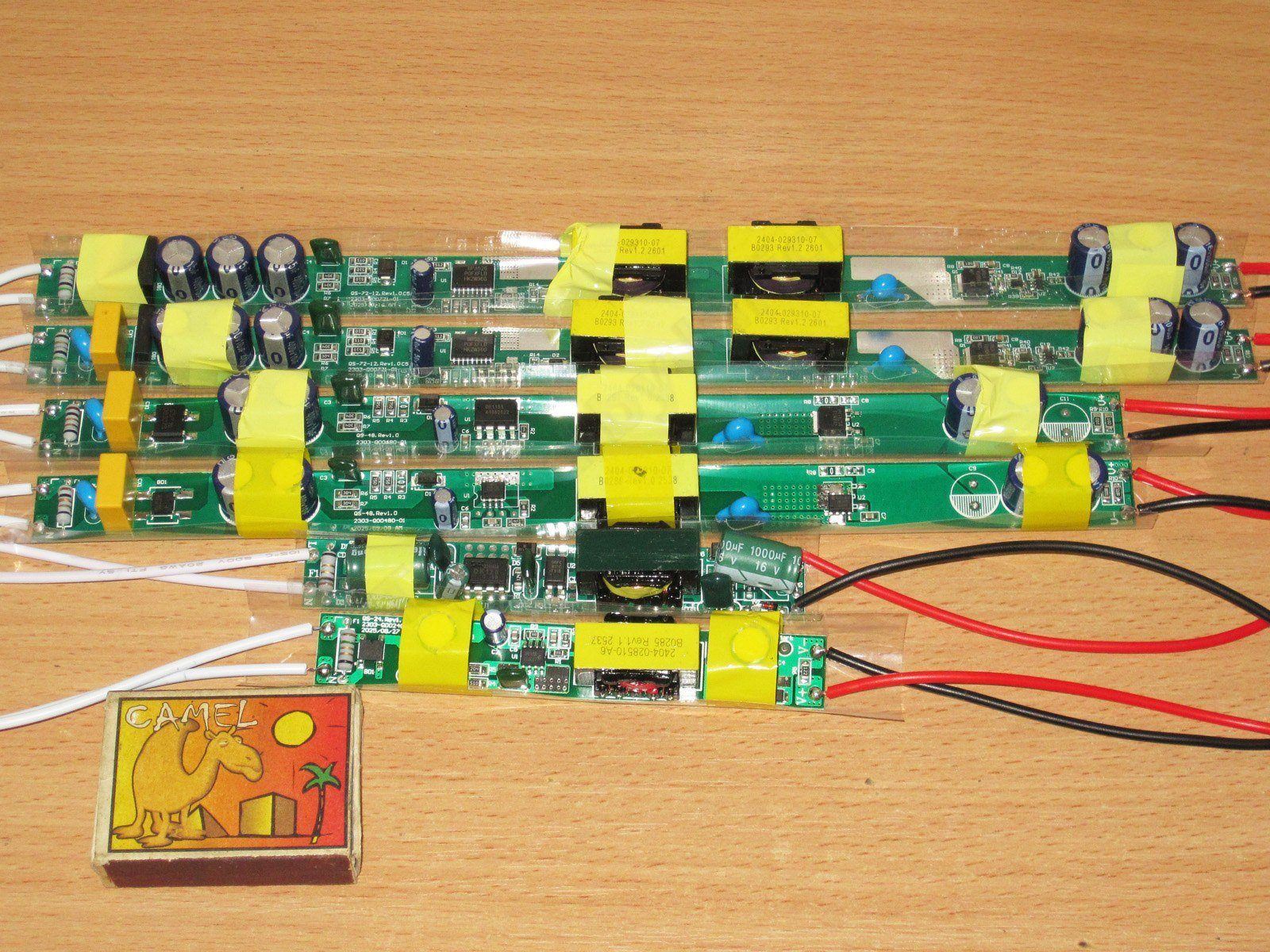
We have six power supply models, all rated at 12 V, with power ratings of 18, 24, 36, 48, 60, and 72 W, and corresponding currents of 1.5, 2, 3, 4, 5, and 6 A. The end caps are shown separately in the photo; I just wanted to see what was inside right away, and couldn’t be bothered to put them back on.
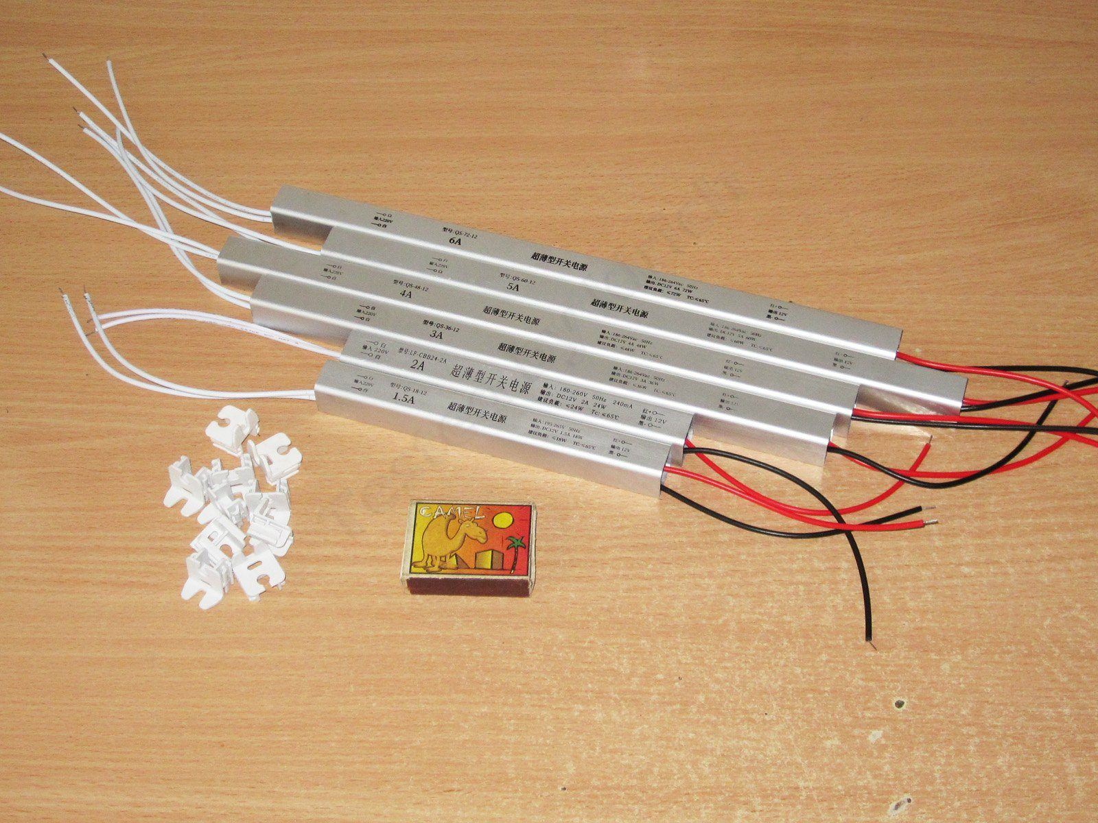
The power supply cases are made from the same extrusion, and look identical apart from their length. The polarity markings on the case match the wire colors, and the wires are arranged the same way too, which is handy if you need to replace one.
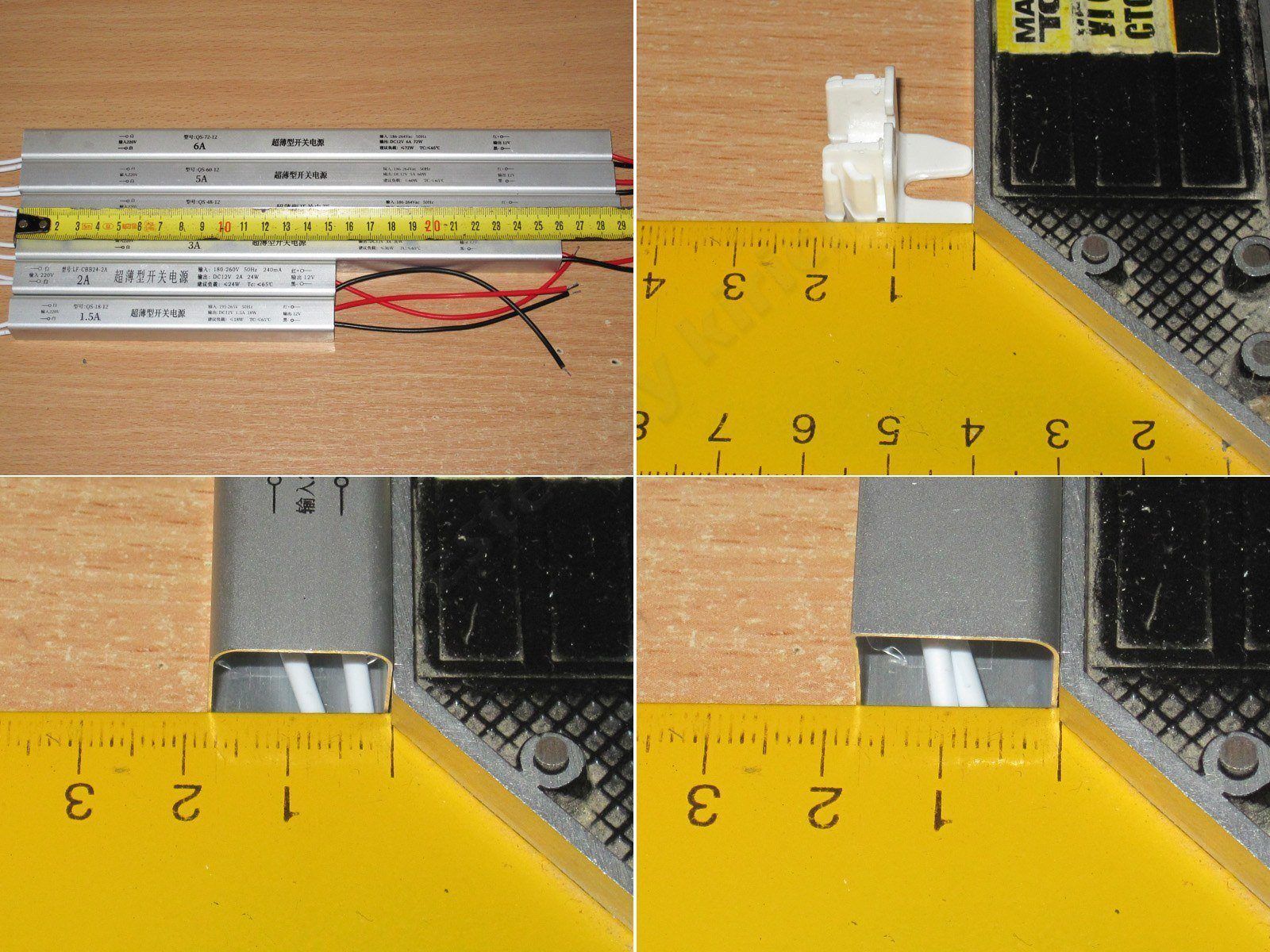
You can estimate the case dimensions from the photo with the tape measure. The end caps add about 11 mm on each side, and the cross-section is around 18 × 18 mm.
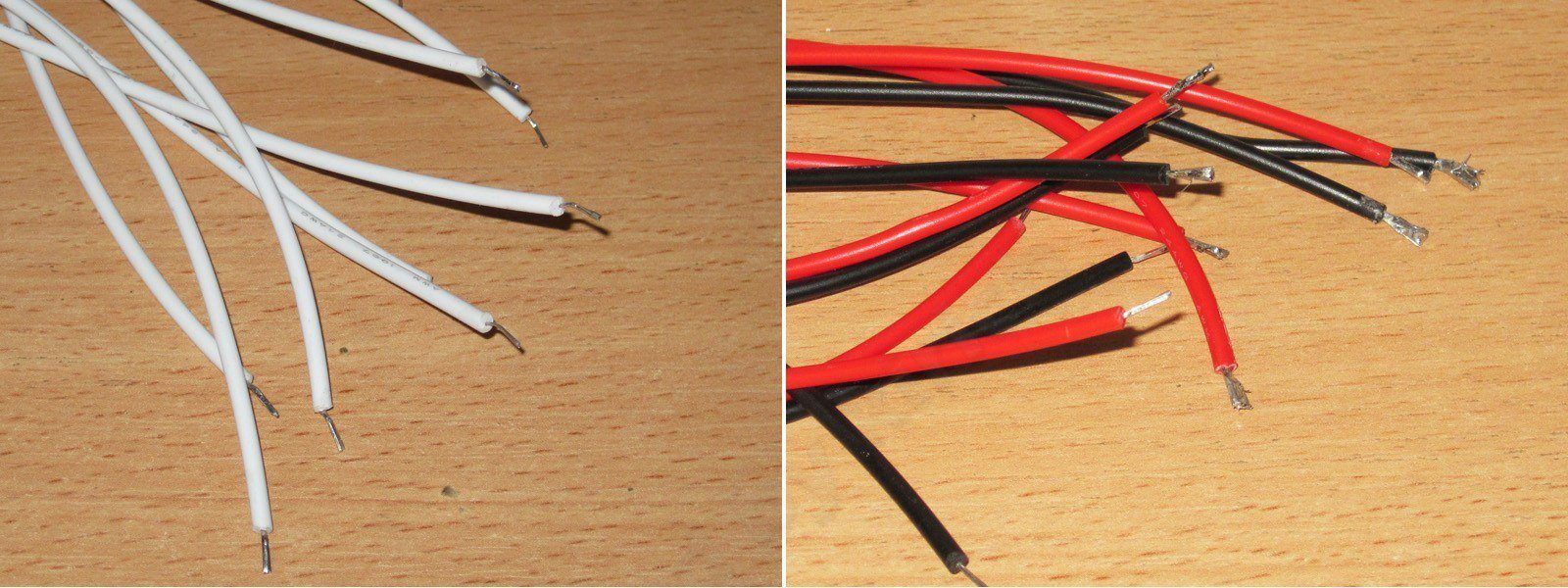
The wires are pretty poor: the insulation is stiff, and the conductors themselves are on the thin side, especially the input wires. The output wires aren’t exactly thick either, though they’re probably adequate for the rated currents. I wouldn’t rule out the conductors being something other than copper, although they solder well.
Here are the insides of all the supplies side by side. The first thing that stands out is that they use transformers of the same size (and, indirectly, power, since their operating frequencies are roughly the same). Only the 60 and 72 W models have two transformers. Even at this early stage, we can make a rough estimate:
The transformers are probably rated for around 30–35 W. That means the ones in the 18, 24, and 60 W models shouldn’t get too hot; the 36 and 72 W models will run close to their maximum operating temperature, and the 48 W model may overheat. But we’ll see how things go during testing.
As usual, we’ll work our way up, starting with the smallest one: the QS-18-12, rated at 18 W and 1.5 A.
One thing all the models have in common is that they look reasonably tidy. At least the boards are mostly clean, and the components are mounted straight.
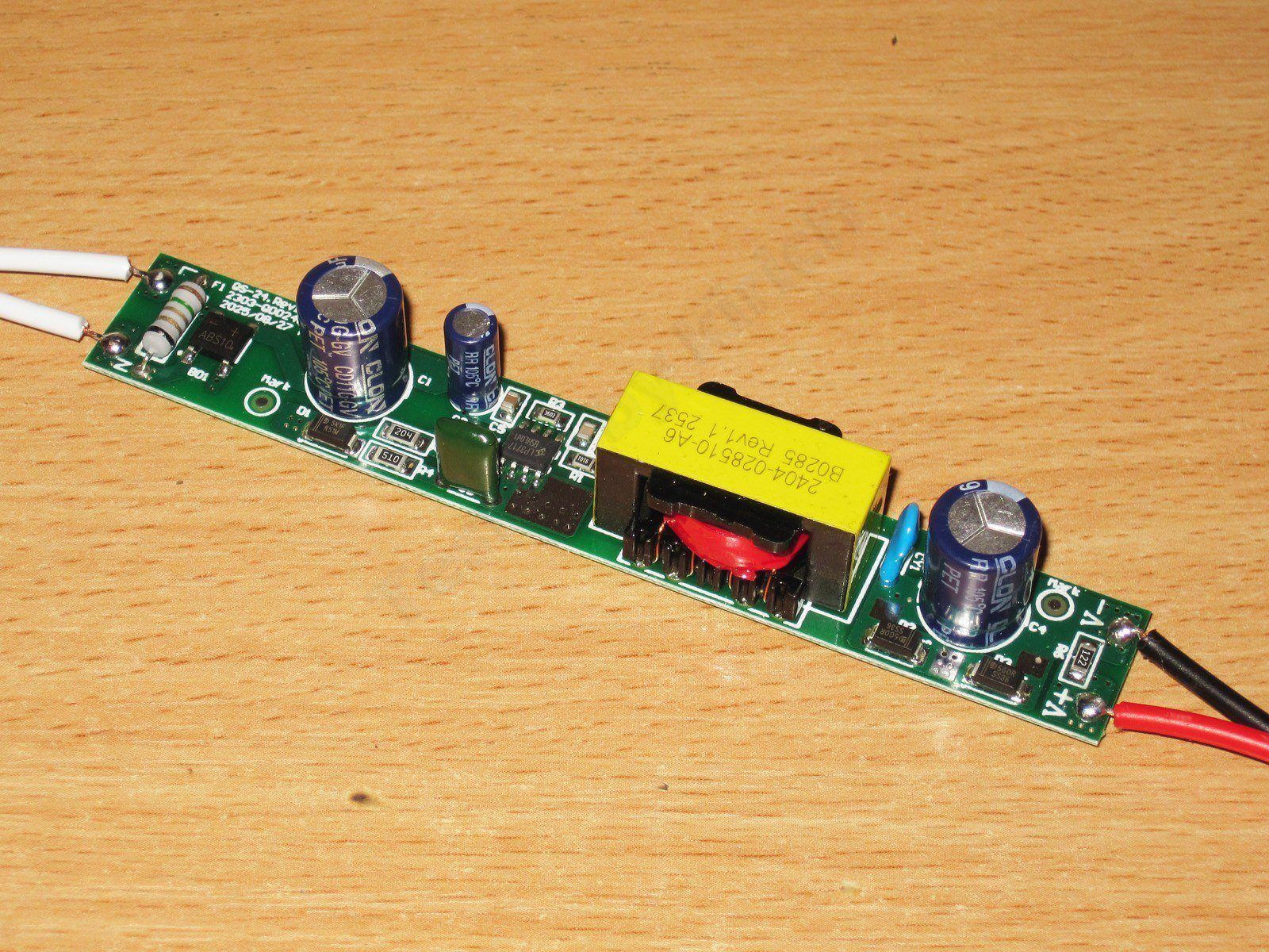
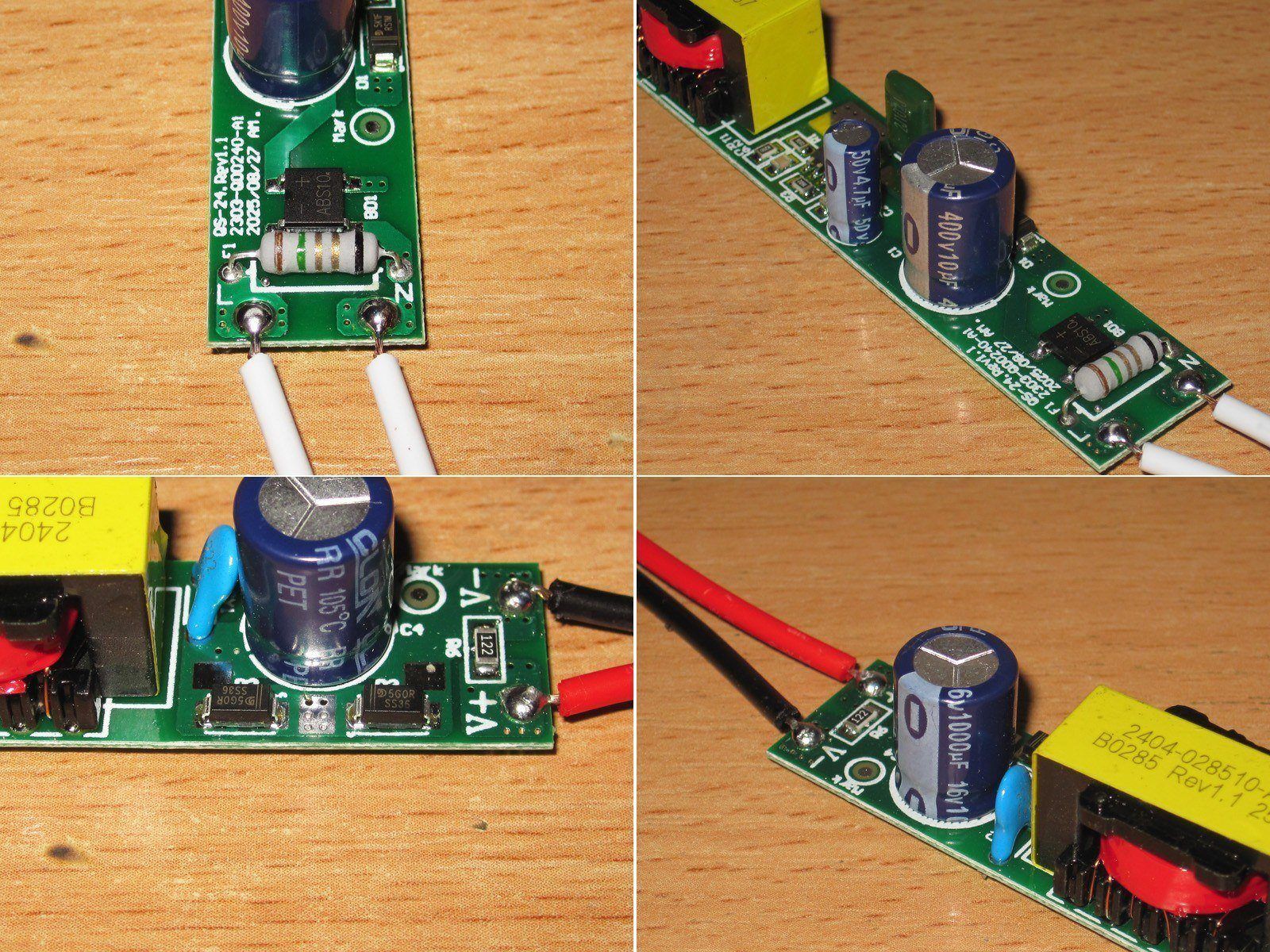
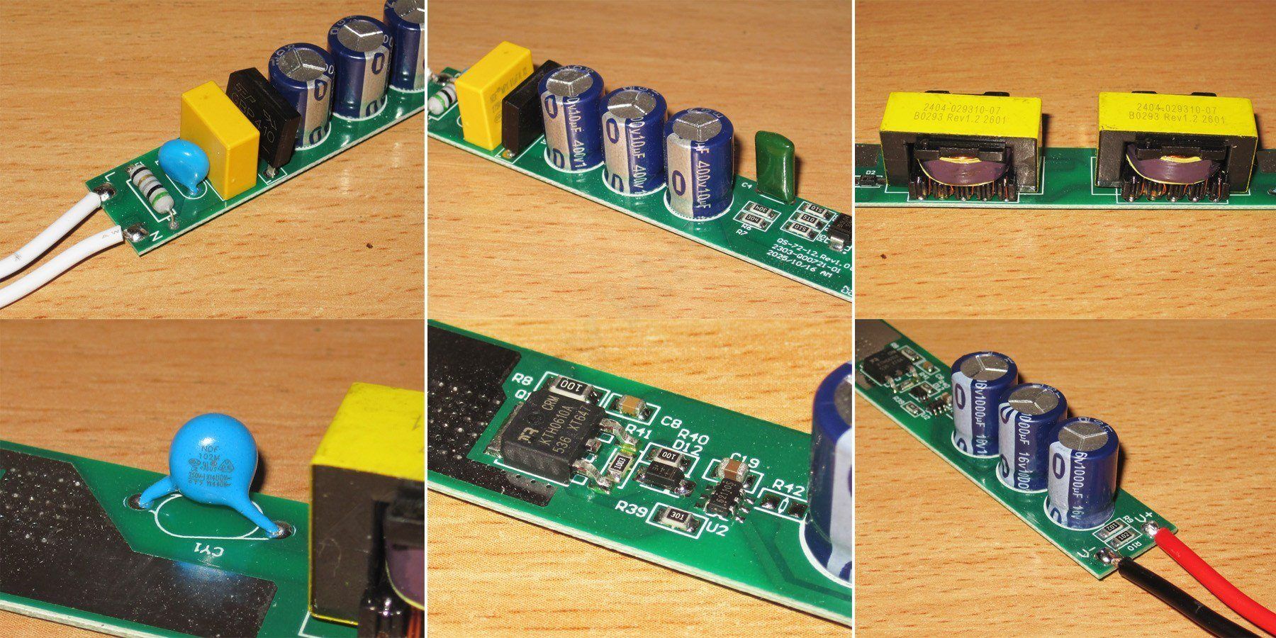
There’s no input filter at all, just a resistor that’s designed to burn out first—in other words, a combination of an inrush current limiter and a fuse. There’s a small bridge rectifier next to it, and that’s it.
The input capacitor is 10 µF, 400 V; on the output there are two diodes connected in parallel and a 1000 µF, 16 V capacitor. If we ignore the lack of an input filter, the minimum necessary components are there, though the capacitance seems a bit low for the rated power.
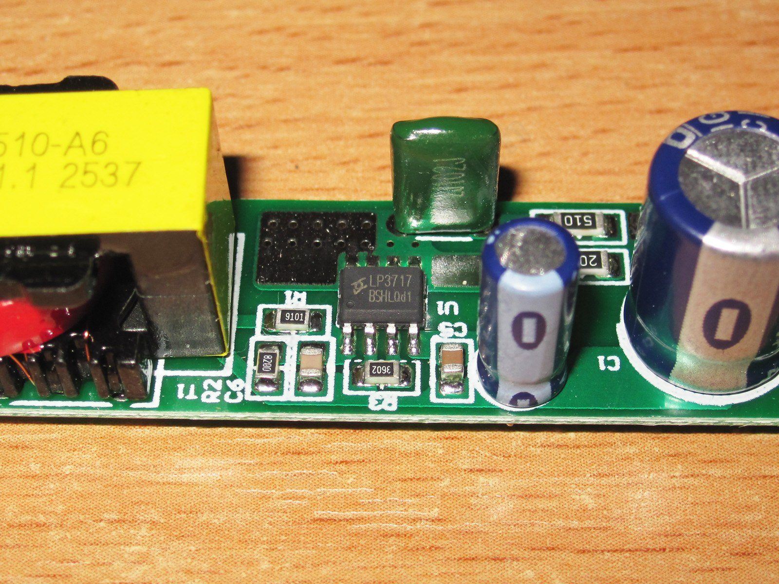
A PWM controller with a built-in high-voltage transistor, plus a whole bunch of protections, including overtemperature protection. That’s great, but the Chinese wouldn’t be Chinese if they didn’t try to pull a fast one. The thing is, judging by the description, this is a 12 W PWM, not an 18 W one — link.
The second issue, which we immediately pointed out to the manufacturer, is that the interwinding capacitors are ordinary high-voltage ones, rated for just 1 kV. This is absolutely unacceptable.
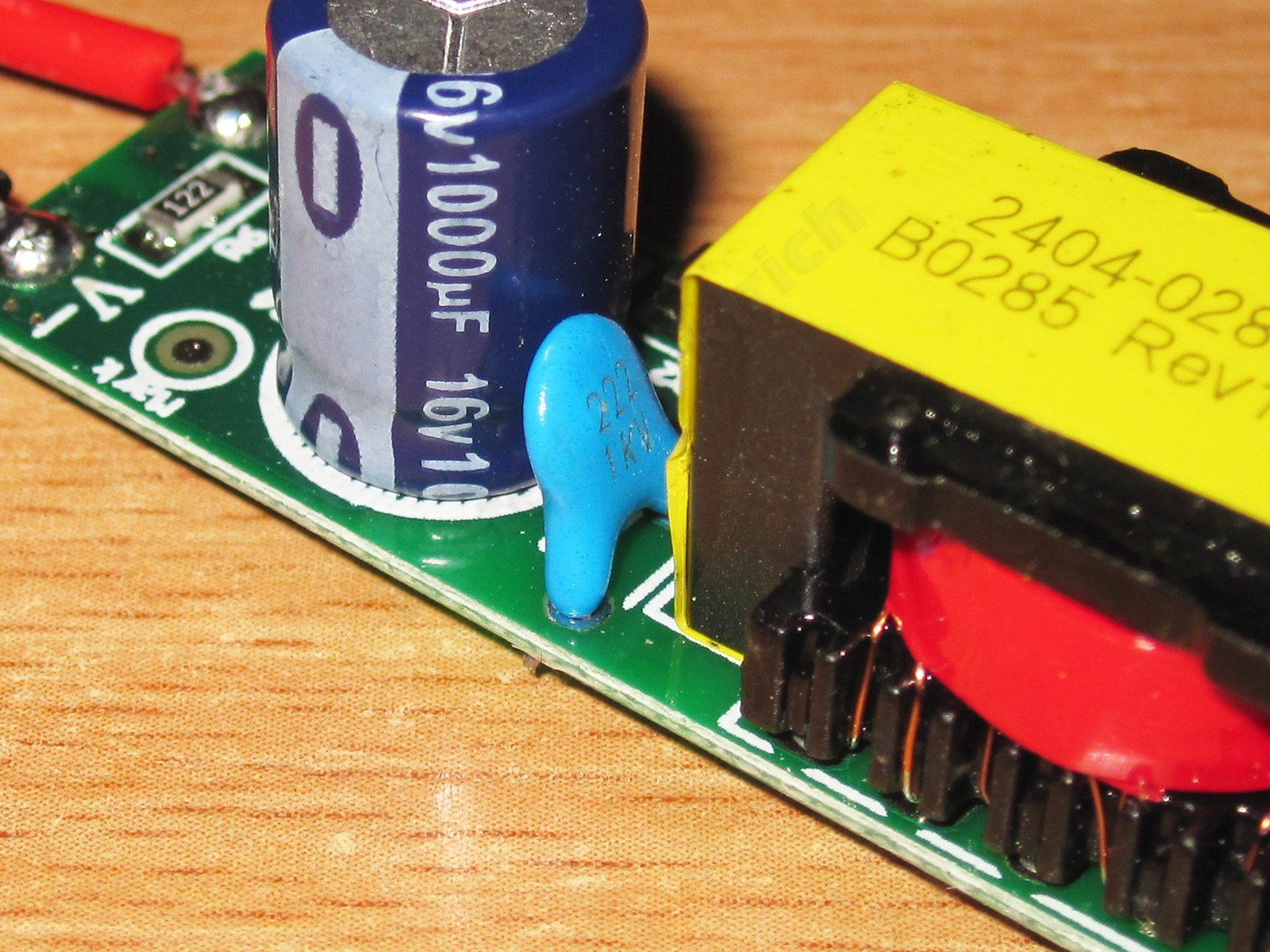
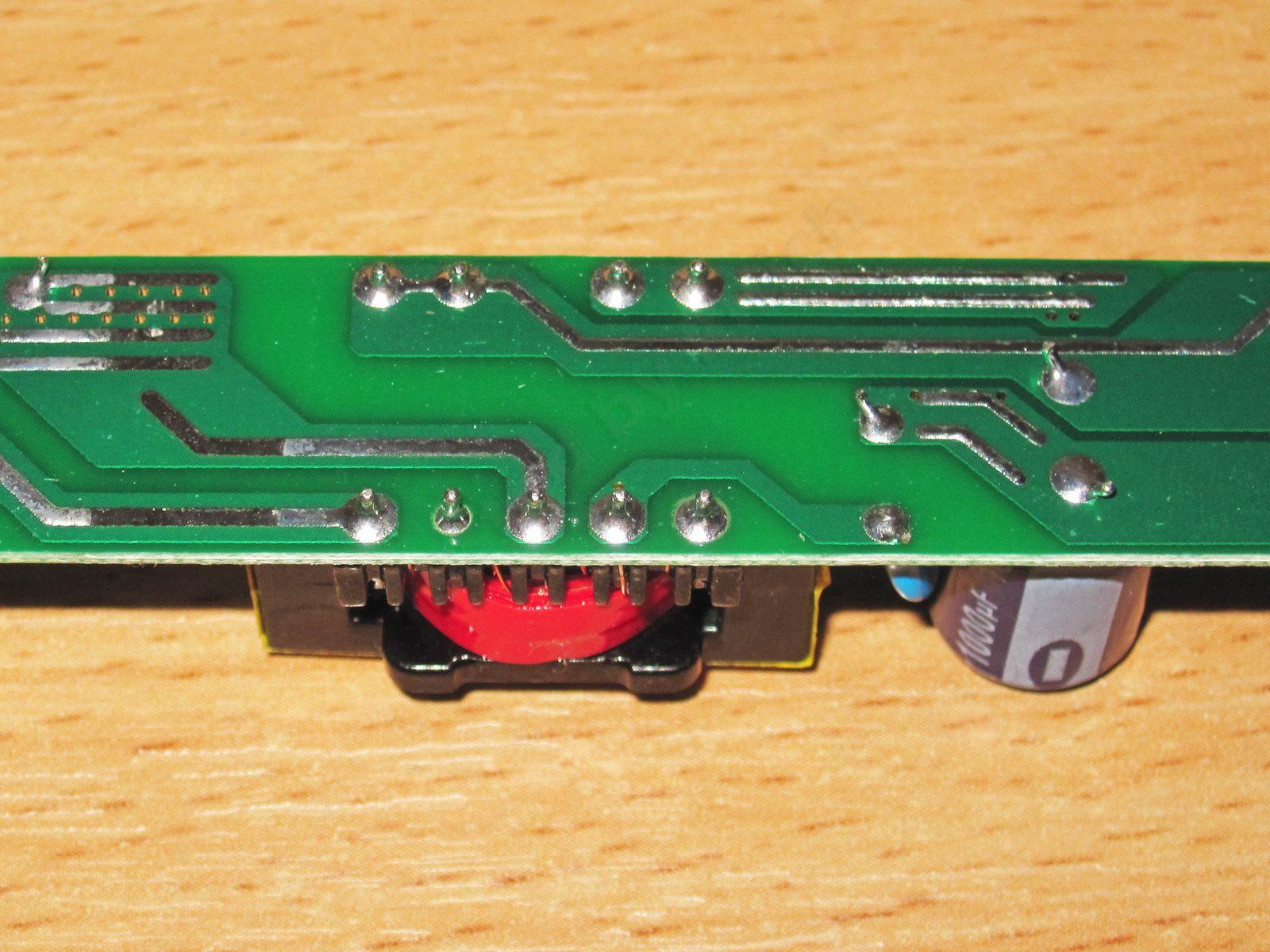
As I already wrote, the boards are very neatly made, both top and bottom.
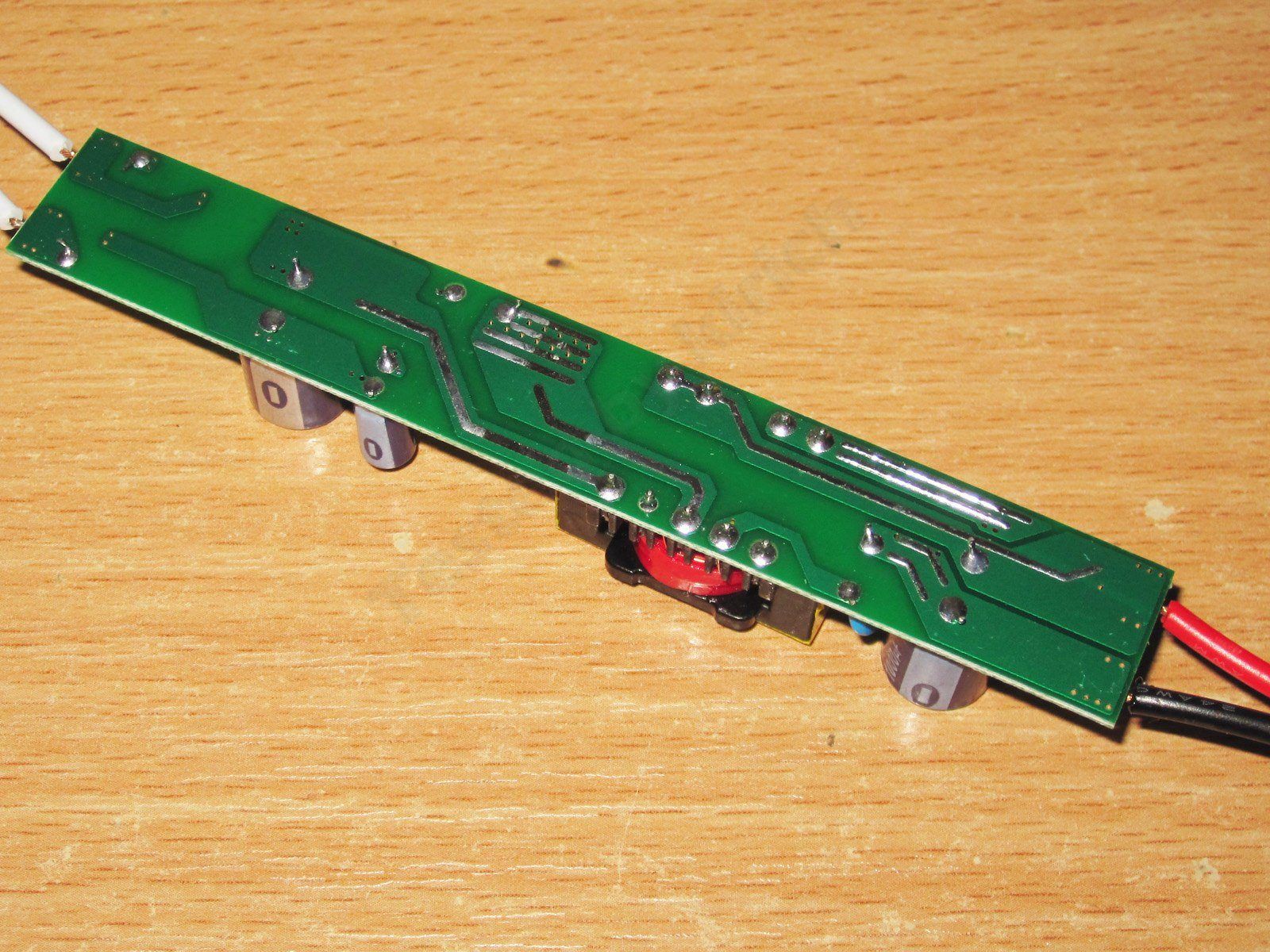
There are no electrical safety concerns (apart from the capacitor); the clearances are quite adequate, partly helped by the fact that there is no feedback from the output.
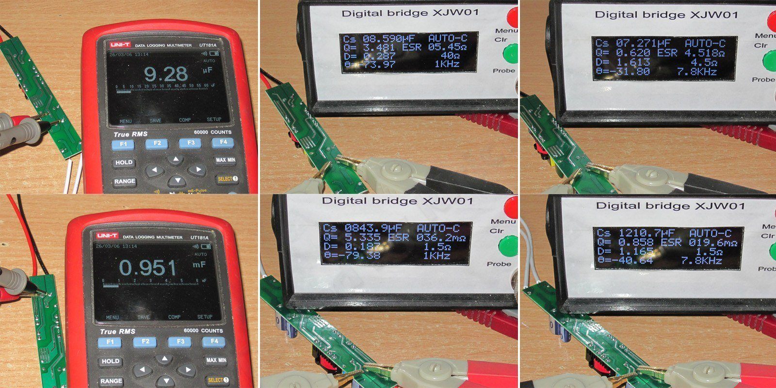
Since almost all the power supplies use the same capacitors and differ only in how many they have, I decided to take more extensive measurements so I could simply add up the results later.
The input capacitor measured 9.28 µF with a multimeter and 7.3–8.6 µF, depending on frequency, with an LCR meter; ESR was 4.5–5.5 Ω.
The output capacitor measured 950 µF with a multimeter and 844–1210 µF with an LCR meter; ESR was 20–36 mΩ.
Basically, I can't say anything good or bad about it: same old, same old. Speaking of which, Fnirsi sent me an LCR meter, so there'll be a review coming :)
The power supply's output voltage rises slightly with load current, and the overcurrent protection kicks in above 1.6 A, which is perfectly normal. It's pretty clear this is a 12 W PWM, since manufacturers usually leave more headroom for overloads. They took advantage of that and rated these at 18 W. Well, what can I say—they do manage it :)))
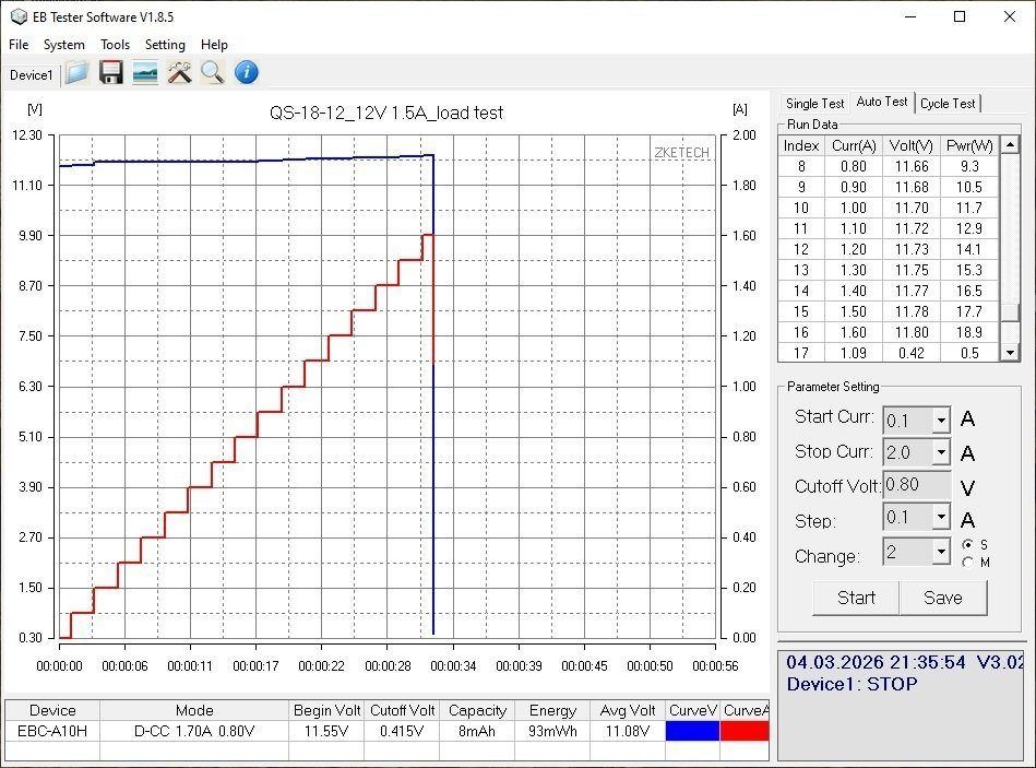
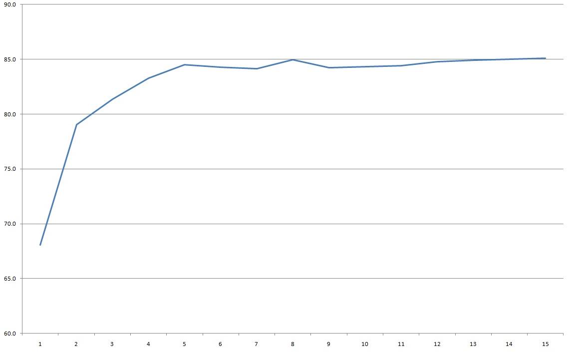
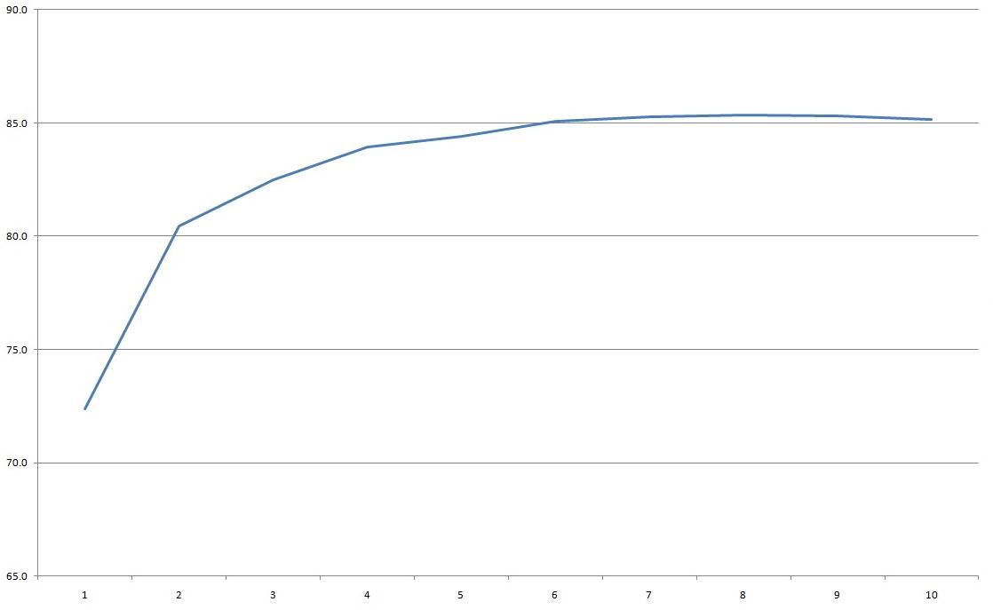
The no-load voltage is 11.55 V, and power consumption is about 0.1 W. Efficiency was measured from 0.1 to 1.5 A in 0.1 A increments and came out to 85%.
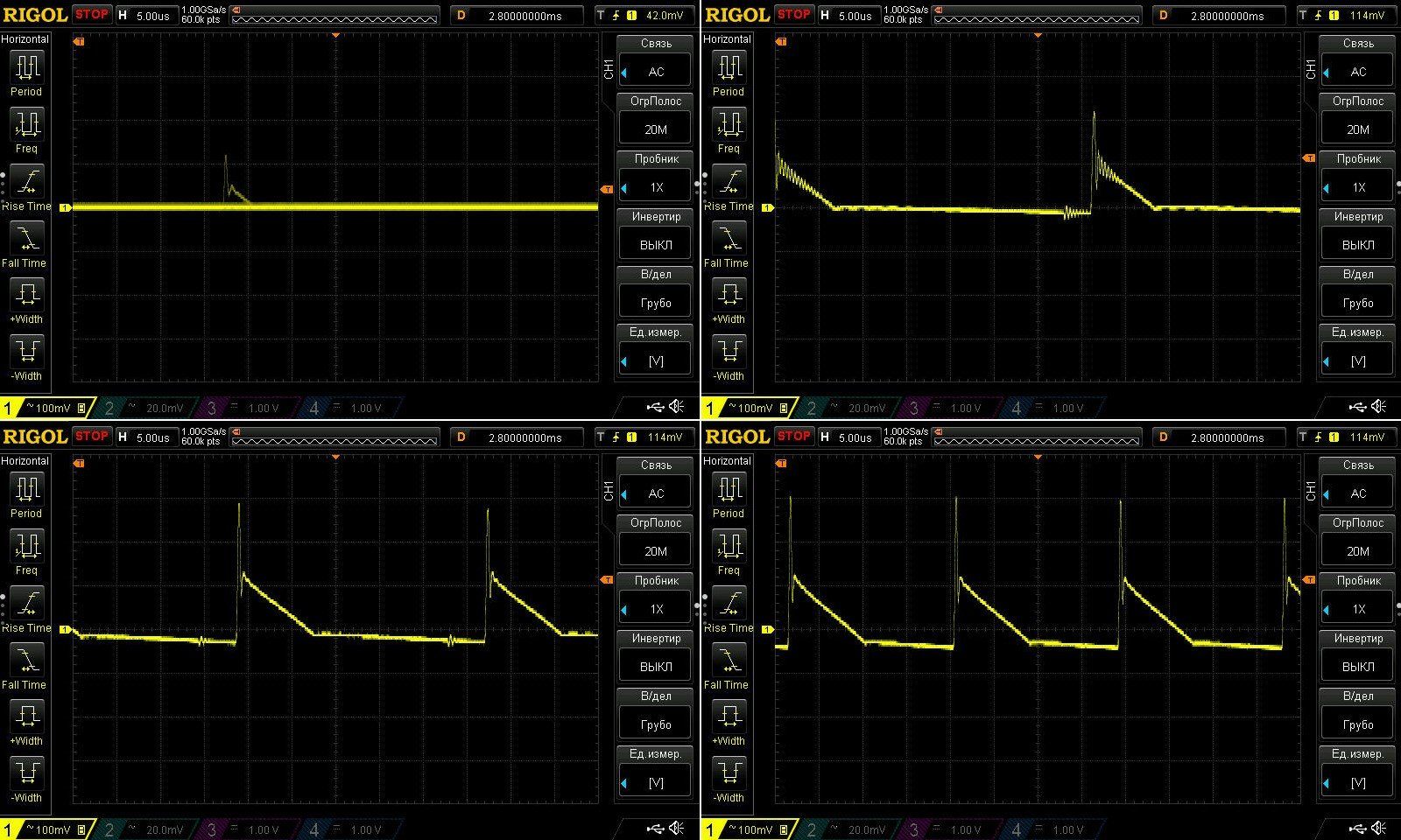
Ripple with no load and at currents of 0.5, 1, and 1.5 A. I have to say, everything looks fine here: 350 mV including the spikes, and about 180 mV for the main ripple.
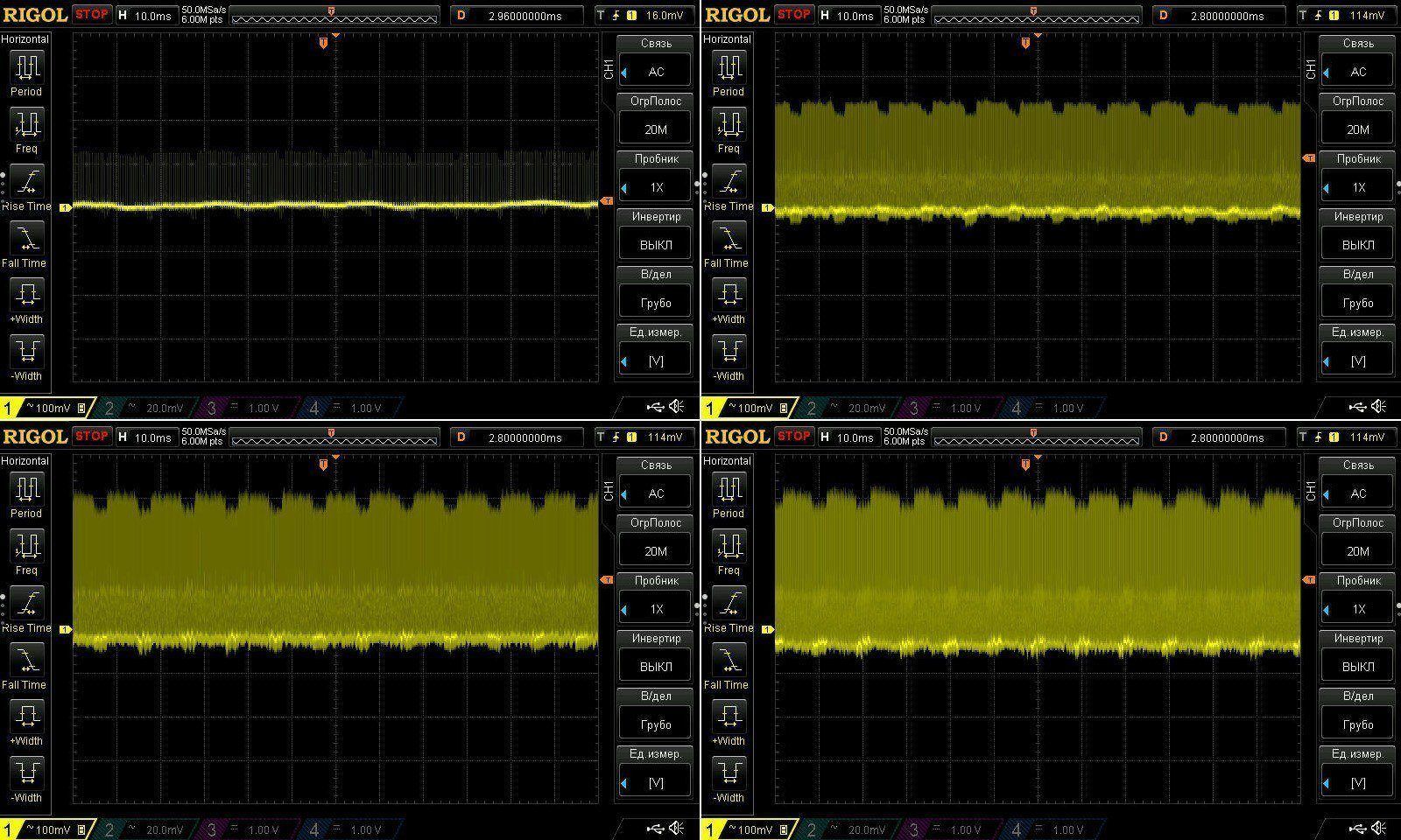
There were no issues with ripple at 100 Hz either, though in my opinion the input capacitance is still a bit low.
The thermal test was simple: just two operating points, at 1 and 1.5 A, but it ran for a long time—almost an hour and a half.
As I already wrote, the output voltage rises with load, and it also rises with temperature: when the power supply was hot, the voltage was about 0.1 V higher than when it was cold. Still, that's just an observation, since it doesn't affect operation at all and everything remains within tolerance.
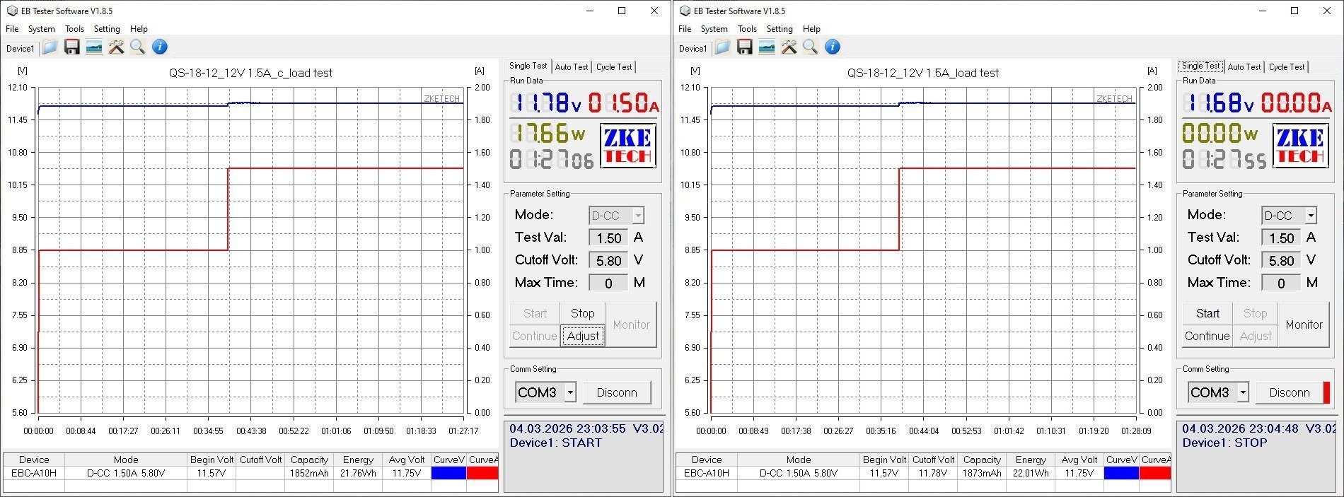
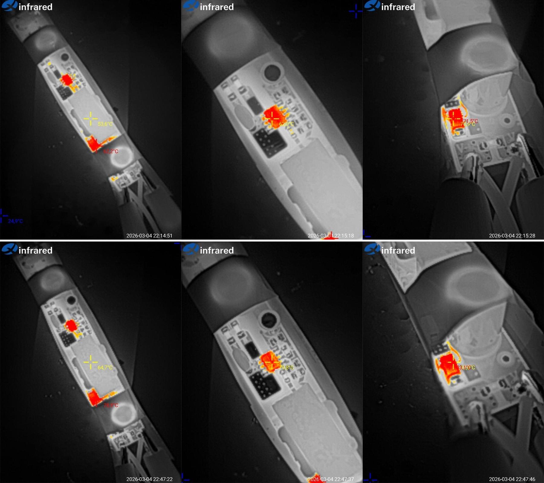
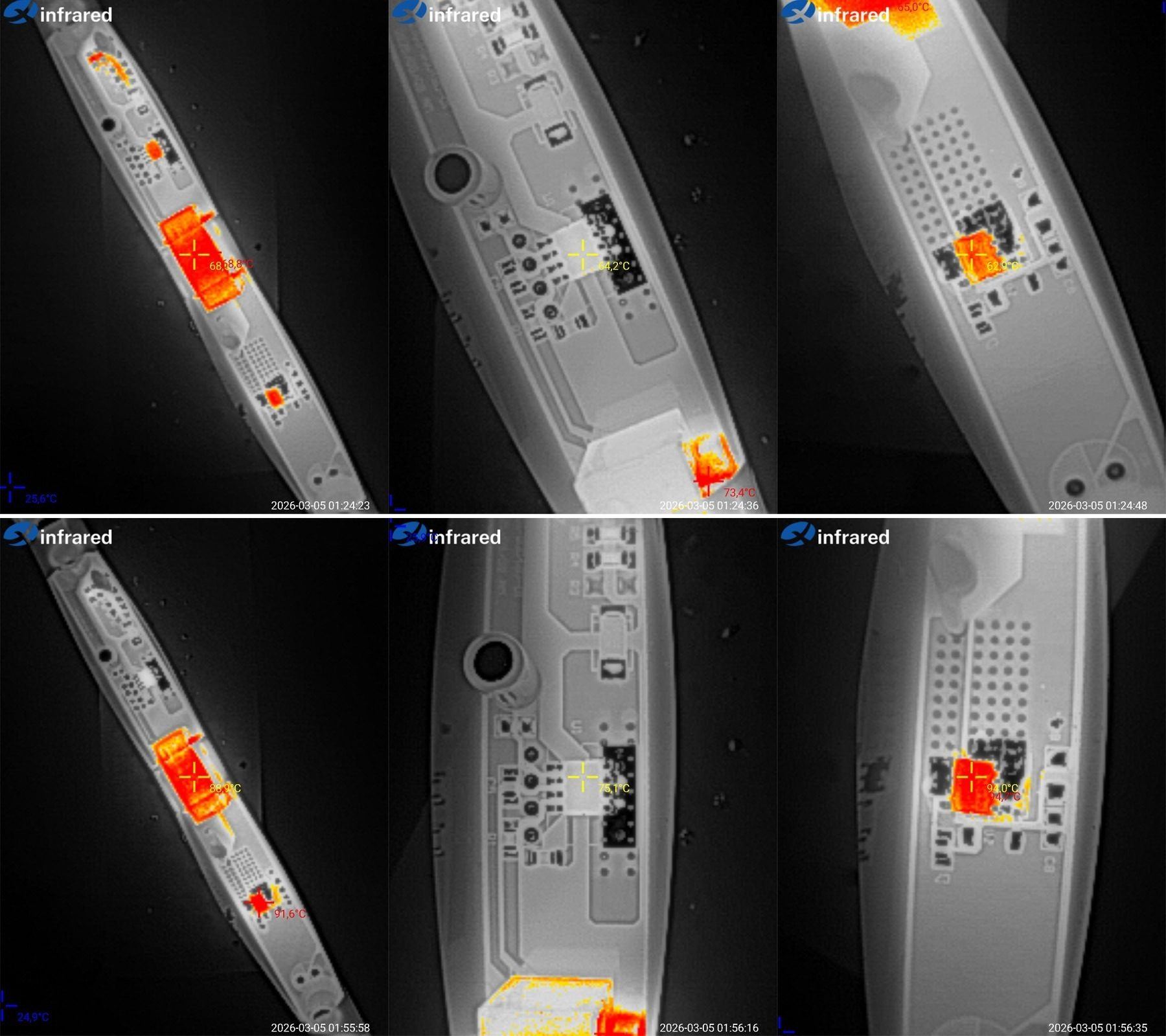
The temperatures of the main components at 1 and 1.5 A, respectively.
At 1 A: transformer 54°C, PWM 62°C, diodes 71°C.
At 1.5 A: transformer 65°C, PWM 80°C, diodes 93°C.
Basically, as I expected, the transformer is almost cool, relatively speaking. But as it turned out, even the PWM runs without overheating and with a decent margin. Even so, I'd recommend using this power supply at up to 15 W for extended periods.
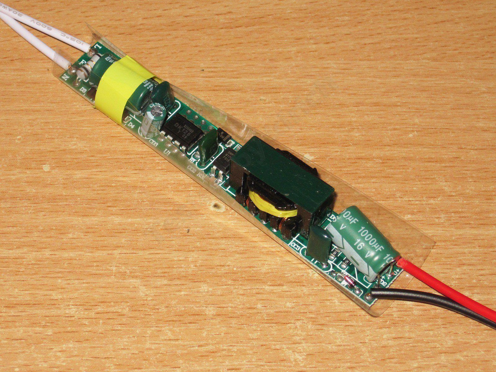
LF-CBB24-2A model, 24 W, 2 A. I thought I might have had a similar power supply before, but no, it just seemed familiar :)
The input side is the same as the previous model, with just a resistor. The bridge rectifier uses discrete diodes, though; I think that makes it both better and more compact.
The input capacitor is 15 µF, 400 V, and rated for 130°C.
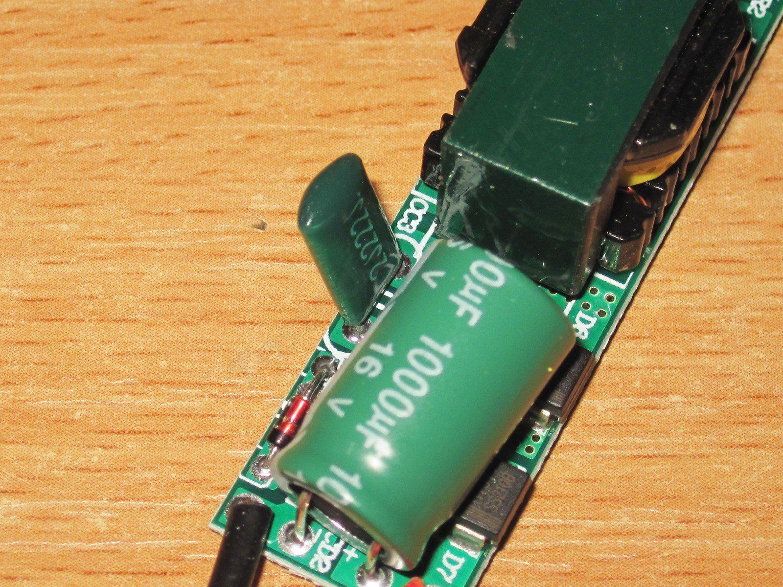
On the output side, there are again two diodes connected in parallel and a 1000 µF, 16 V capacitor. The diodes are rated at 2 A and 100 V, judging by the markings. That’s acceptable.
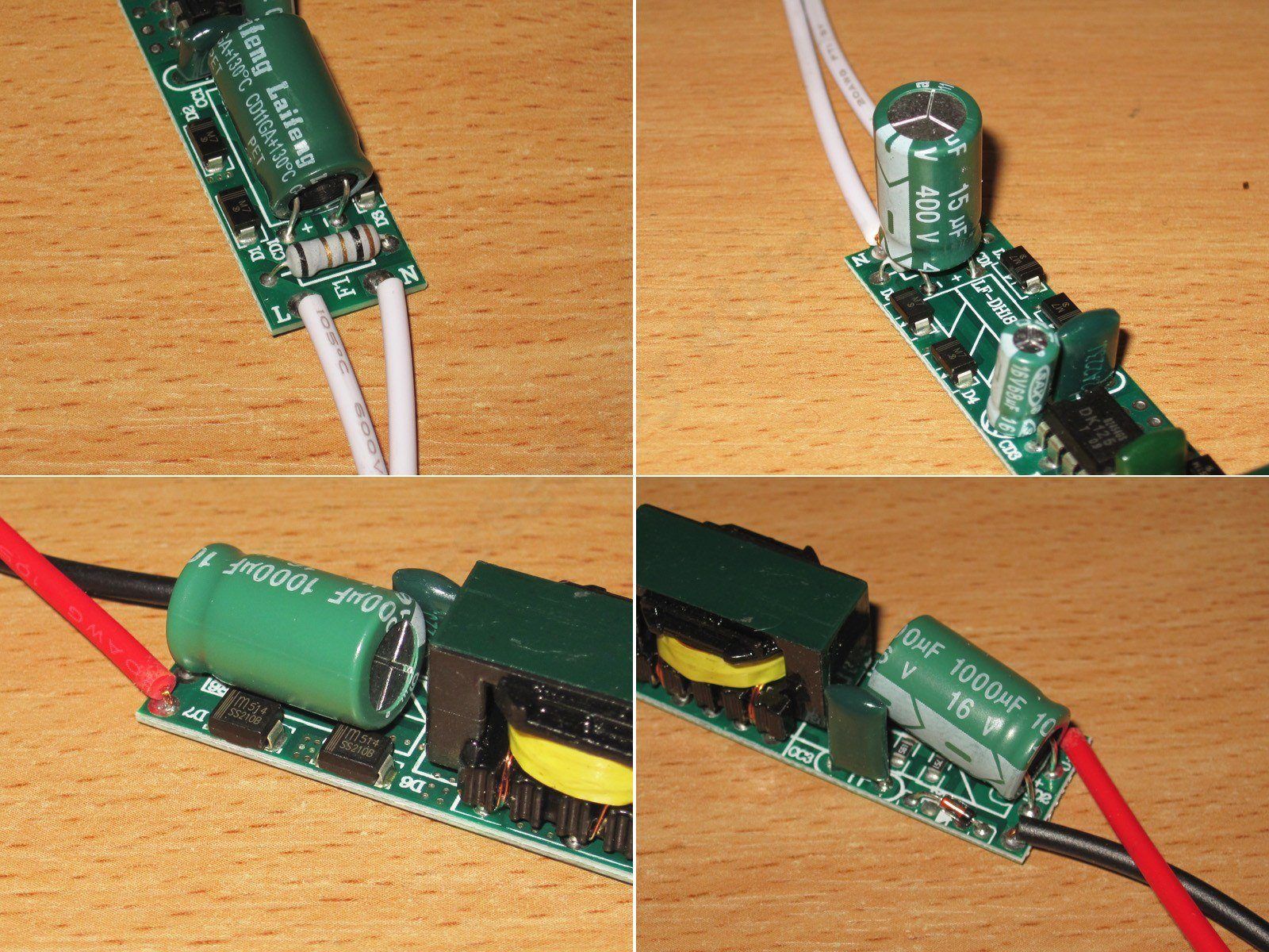
The PWM controller is very common, the DK125, and I have no complaints about it here. It’s rated for 24 W.
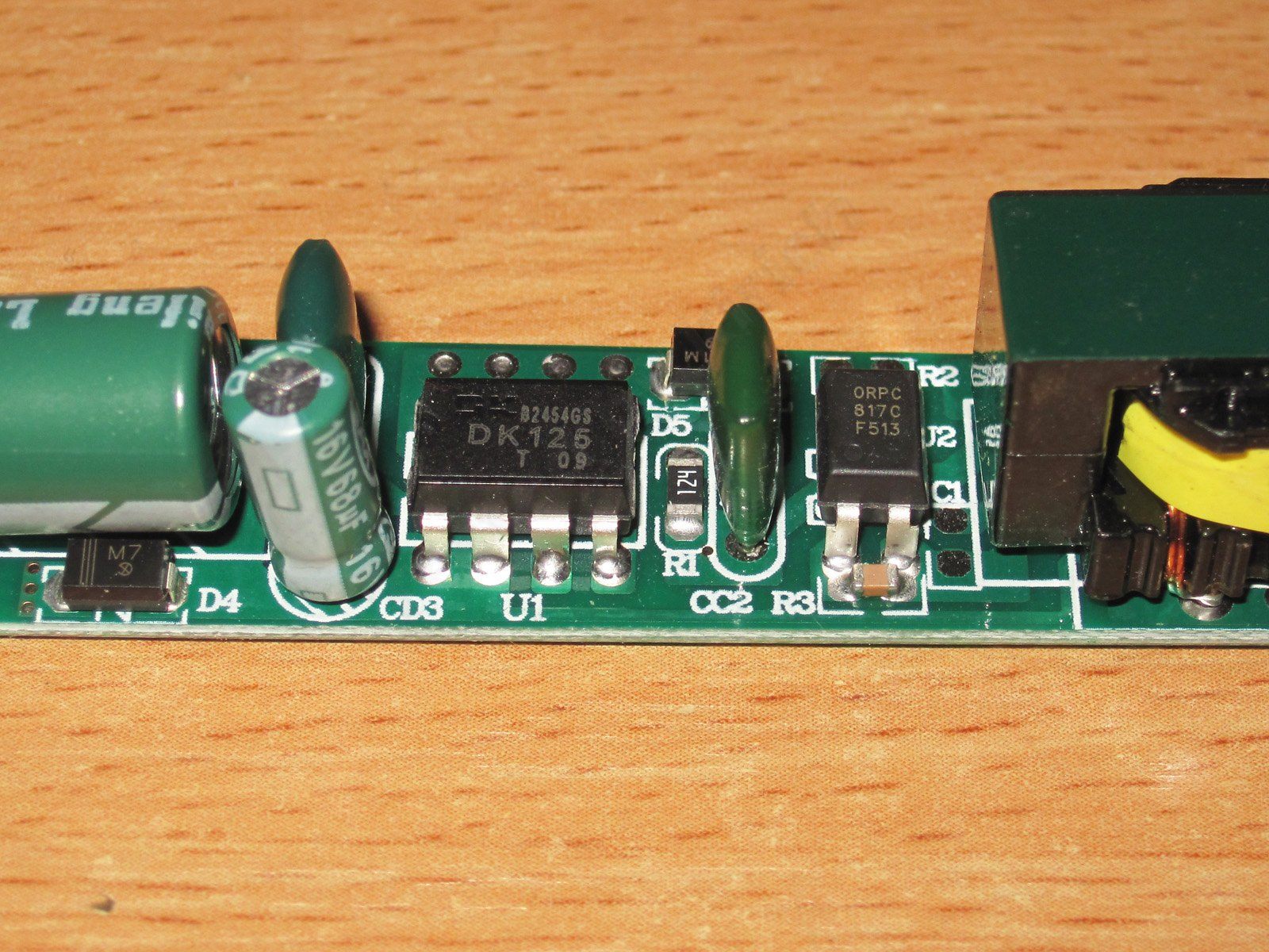
One immediate issue: once again, they used a regular capacitor instead of a Y capacitor, which is not acceptable. I also contacted the manufacturer about this power supply.
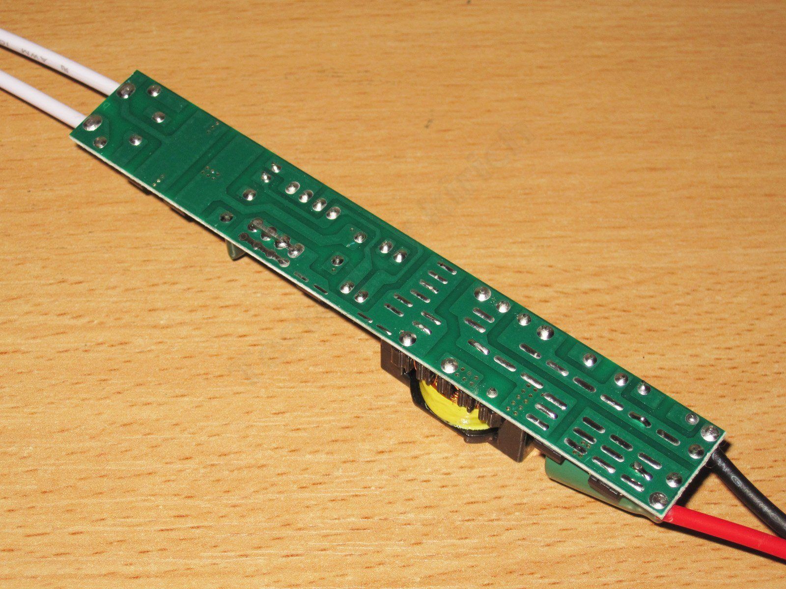
The board is also neatly made, at least at first glance.
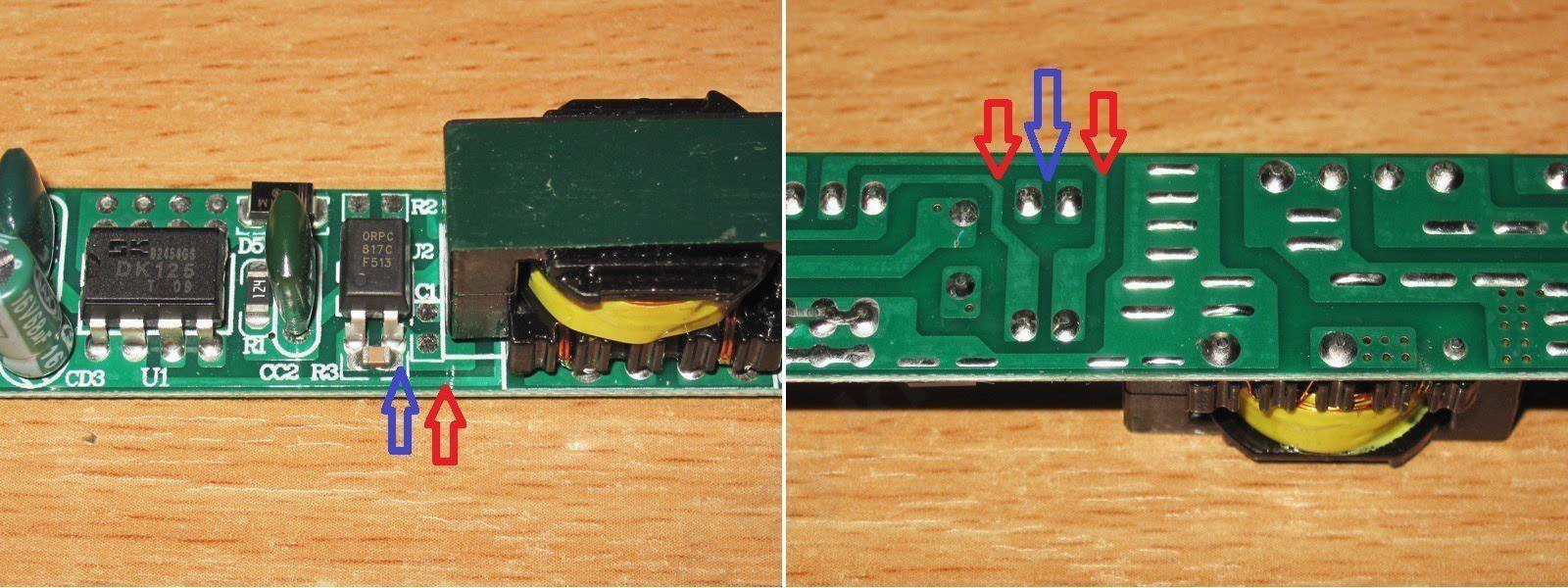
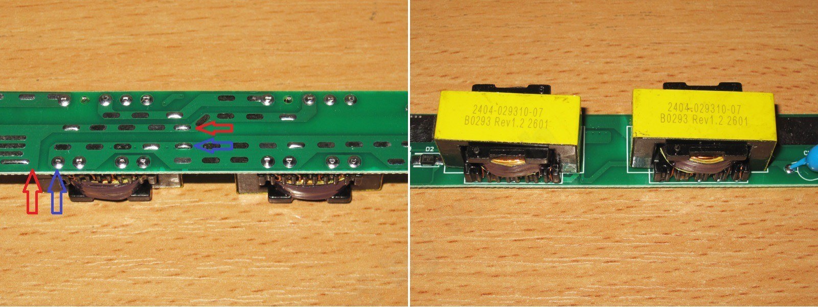
I also found electrical safety issues with the board itself. Here I’ll refer back to the review of similar power supplies with similar problems.
The red arrows mark the traces connected to the mains; the blue ones mark the output traces. This is really bad :(
A coating of potting compound might have helped a little here, though I’d still have spaced the traces farther apart.
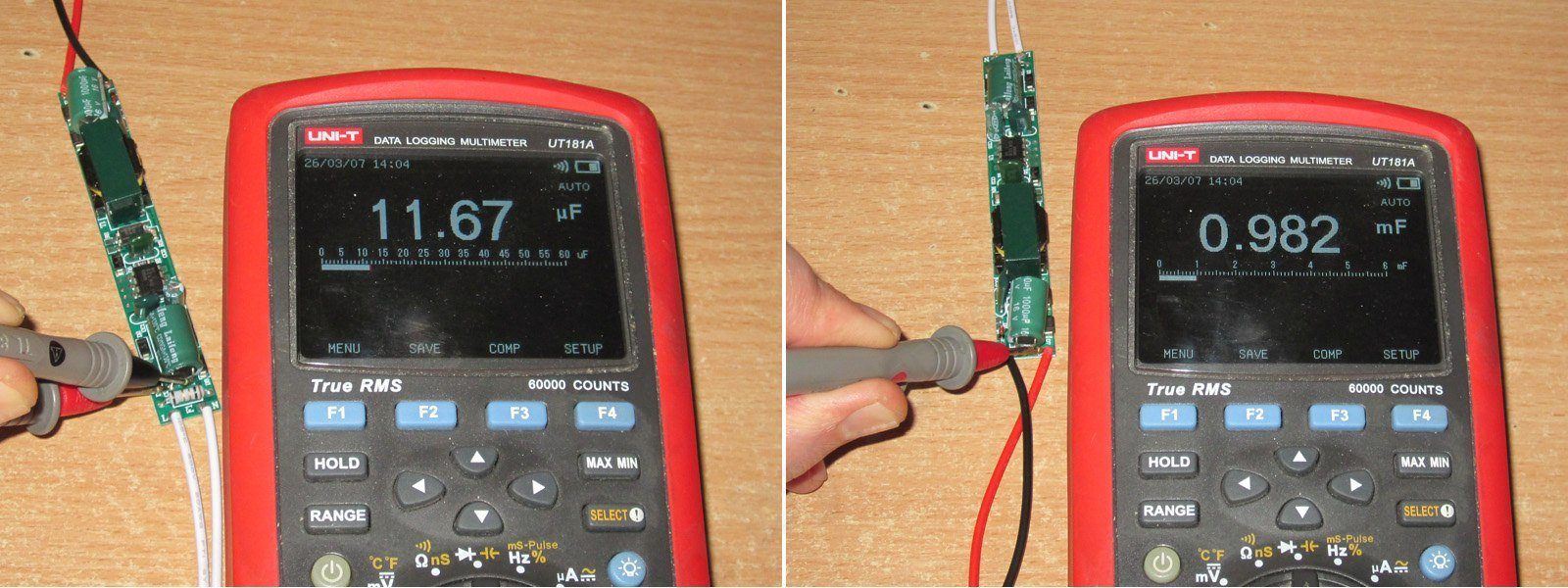
The input capacitor was marked 15 µF, but measured 11.67 µF. It could have been higher; 12 µF is not much for a 24 W power supply anyway. The previous one was similar, with 9 µF for 18 W.
The output capacitor measured 982 µF, which is fine.
Although it’s rated for 2 A, the protection kicks in at 3.6 A. That’s certainly a lot, but given that the limit is set by the controller itself, which is rated for 24 W, it’s acceptable—especially since it has overtemperature protection.
The voltage under load dropped slightly, by about 80–90 mV, but that’s not critical.
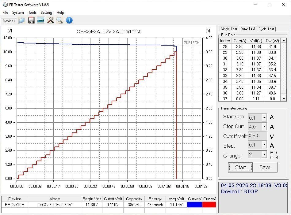
With no load, the output was 11.60 V, and power consumption was about 0.25 W.
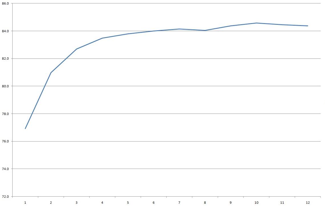
I measured efficiency from 0.2 to 2.4 A in 0.2 A increments and got about 84%, slightly lower than the previous one. That’s a little surprising; I expected it to be about the same.
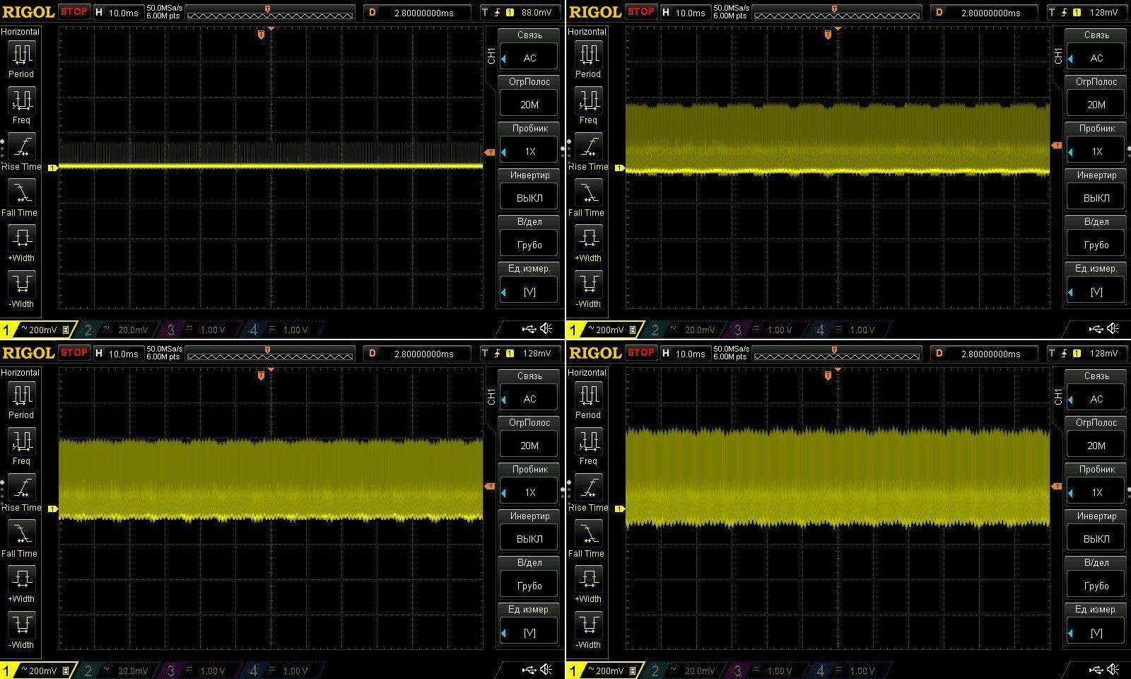
Ripple with no load and at currents of 0.7, 1.4, and 2.1 A. Nothing much to complain about here: the main component is around 250 mV, with peaks closer to 550 mV. That’s normal for budget power supplies without an output filter. A polymer capacitor on the output would have improved things somewhat, but this one has a regular capacitor.
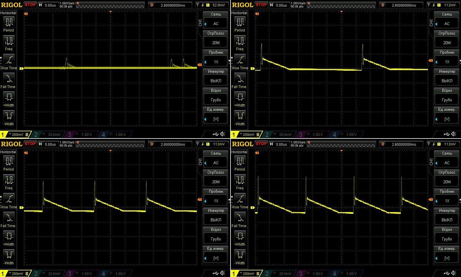
At 100 Hz, there’s nothing to complain about at all; only the overall high-frequency component is visible.
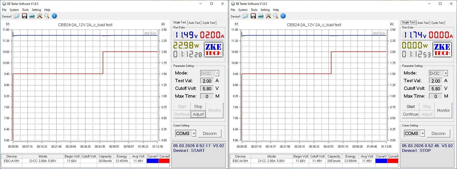
The load test was run at 1.5 and 2 A, for a total of about 1 hour and 10 minutes.
An interesting observation: after the load is switched on, the voltage drops slightly, then returns to roughly its original level and stays there until the current is increased again. In other words, the power supply has a slight positive voltage-versus-temperature characteristic, about 80 mV, which essentially compensates for the voltage drop under load.
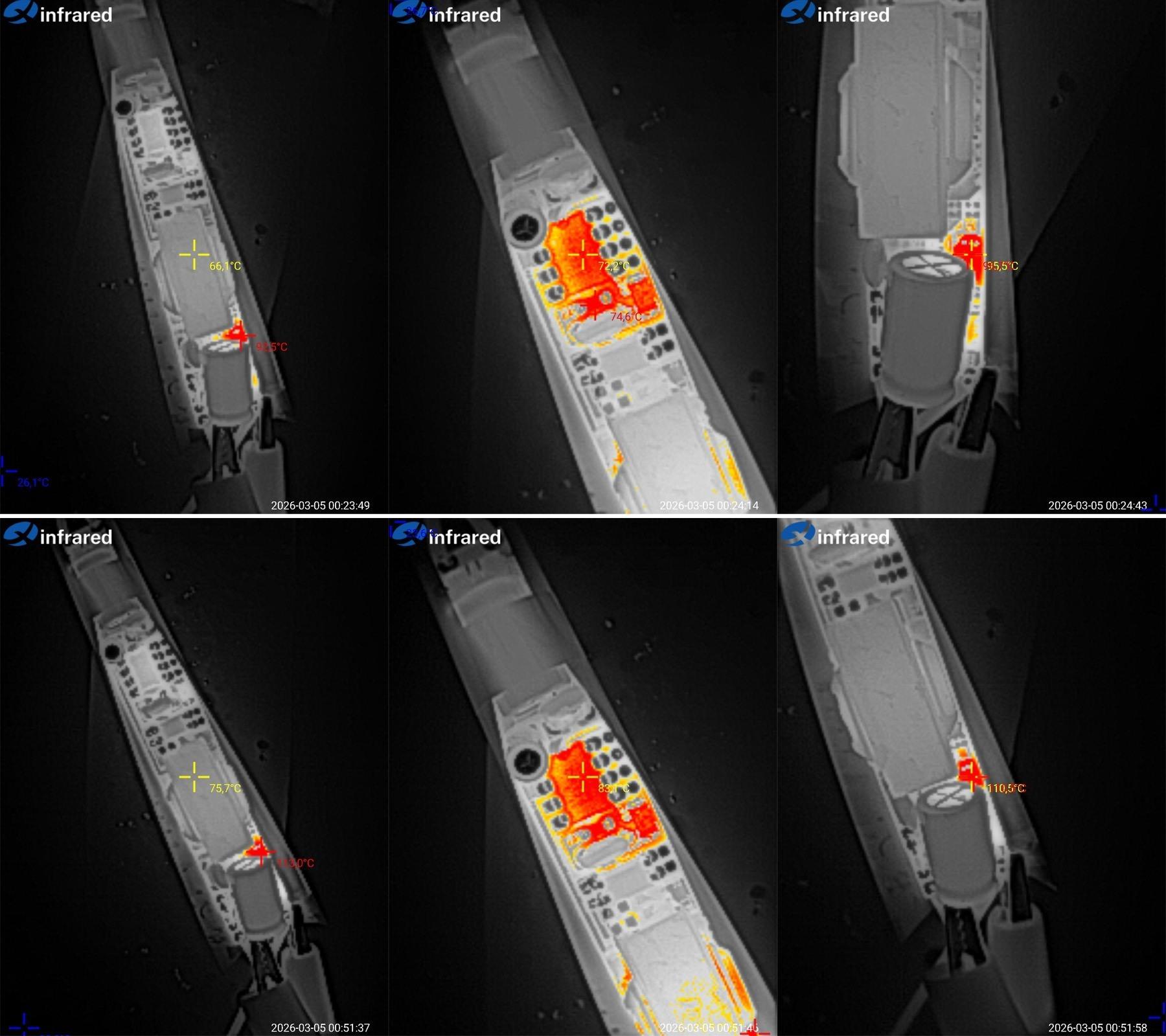
Temperatures at the same 1.5 and 2 A loads.
At 1.5 A: transformer 66 °C, PWM controller 72 °C, output diodes 95 °C. The photo shows that the diode closer to the transformer gets hotter.
At 2 A: transformer 76 °C, PWM controller 83 °C, diodes 110 °C.
The transformer and PWM controller temperatures are both excellent. I expected that from the transformer, but the diode temperature is disappointing: 110 °C at the rated 2 A is rather high.
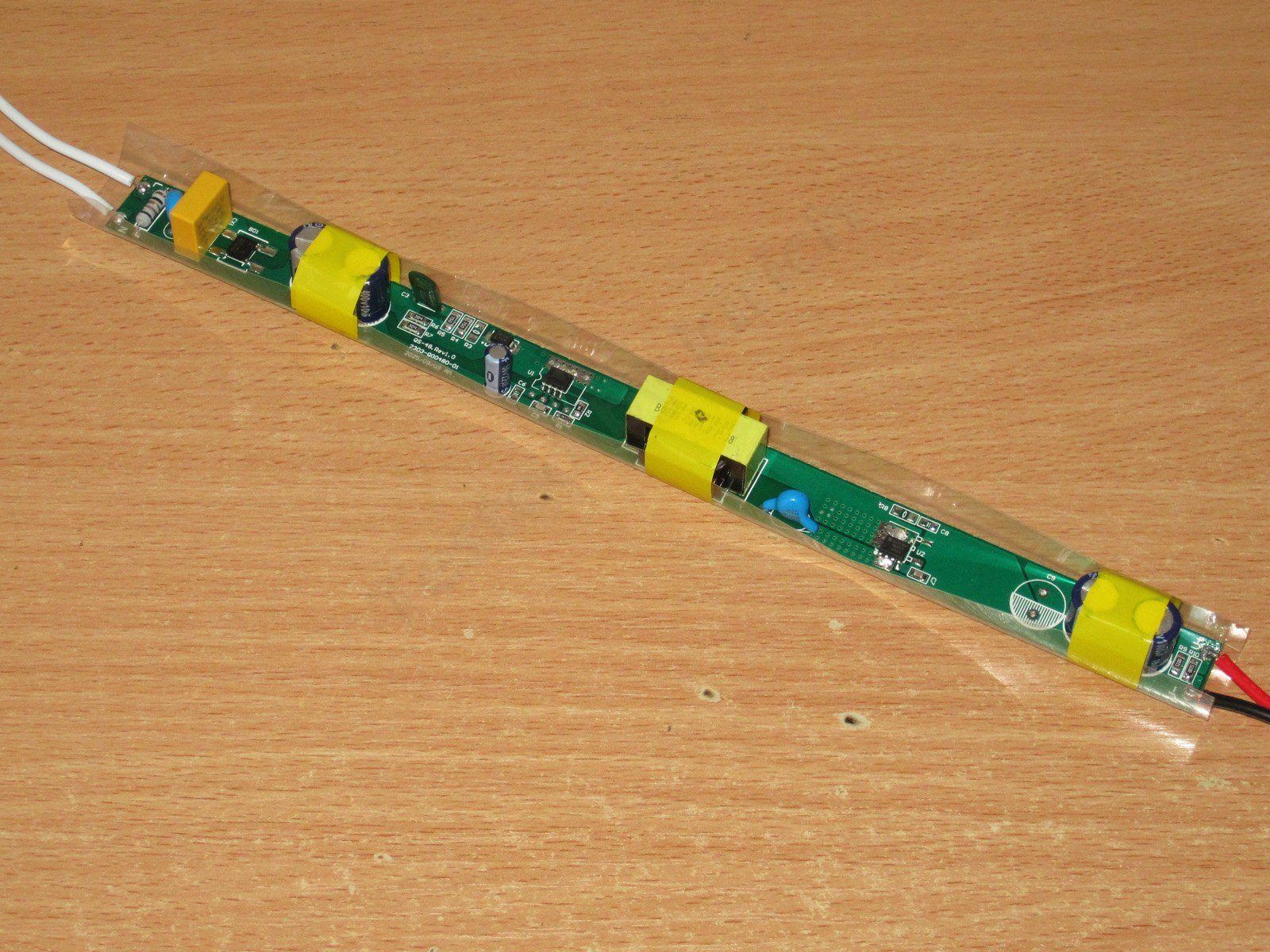
QS-36-12 model, rated at 36 W and 3 A. As I said, based on my estimates, this is about the limit for these transformers. So in theory, we should hit their temperature limit here, but let’s see.
The board is just as neatly made, but noticeably longer than those in the previous models.
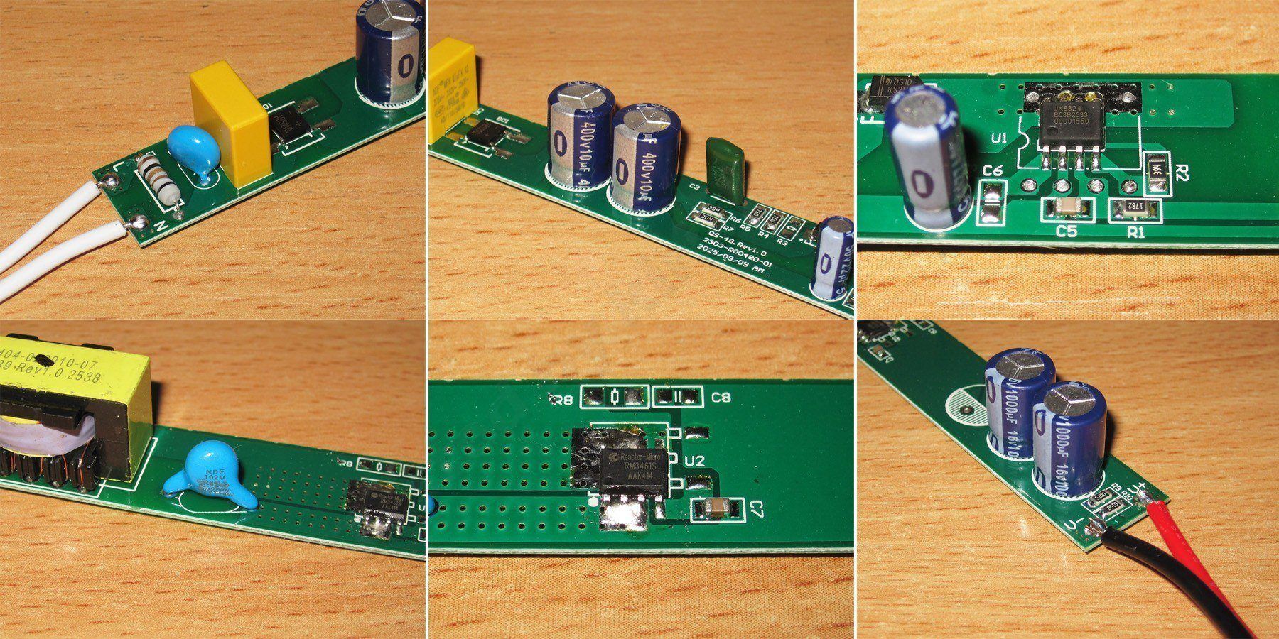
1. In addition to the same resistor and bridge rectifier, this one has an X capacitor and a 470 V varistor. Well, that’s a surprise :)
2. There are now two input capacitors, giving us a total capacitance of around 18–19 µF, again half of what I’d like to see. As a reminder, even for our mains supply, it’s recommended to have about 1 µF per watt of power at the input. Let’s say 1 µF per 1.5 W for a budget design, but 1 µF per 2 W is still a bit low. This could affect reliable startup in cold weather, especially once the capacitors have aged a little.
3. JX8824 PWM controller; I couldn’t find any information about it.
4. This one has a proper Y capacitor. By the way, there’s a lot of free space on the board, but judging by the copper pours, they’re probably being used as an improvised heatsink.
5. At the output, the RM3461S synchronous rectifier chip has a 40 V/15 mΩ transistor built in, according to the information I found. It comes in an SOP8 package and is listed for power supplies rated at 12 W/15 W. It’s not clear what output voltage those ratings apply to, though. Judging by the 40 V rating, it seems more likely to be for 5 V than 12 V, since 12 V power supplies use chips rated for at least 60 V, and often even 100 V. So, it’s all a bit unclear, and I’m not too keen on it.
6. The output has two 1000 µF, 16 V capacitors and ballast resistors rated at a whopping 510 Ω, two in parallel. It looks like the designer was trying to deal with something, since dissipating around 0.6 W for no good reason seems like a bit much.
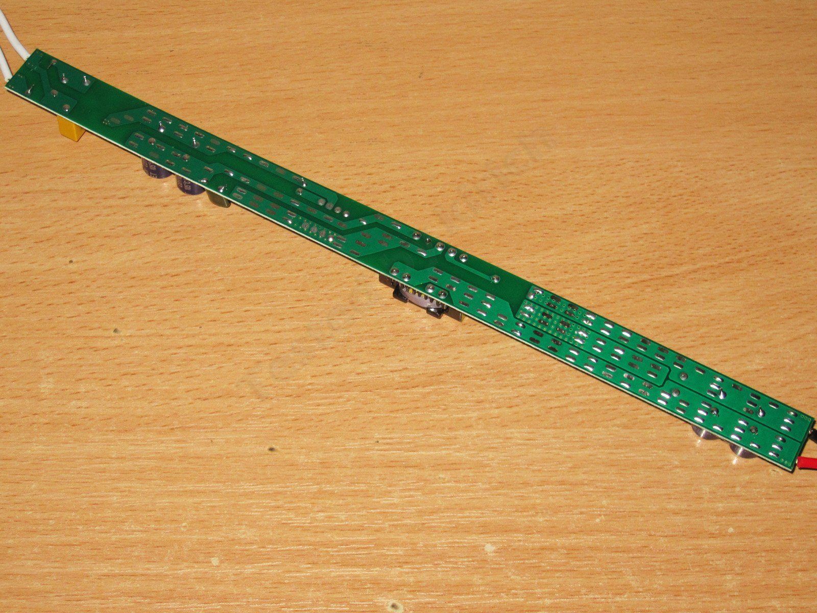
Bottom view. The large copper pours around the output rectifier are clearly visible. It really does feel like the manufacturer was trying to deal with something.
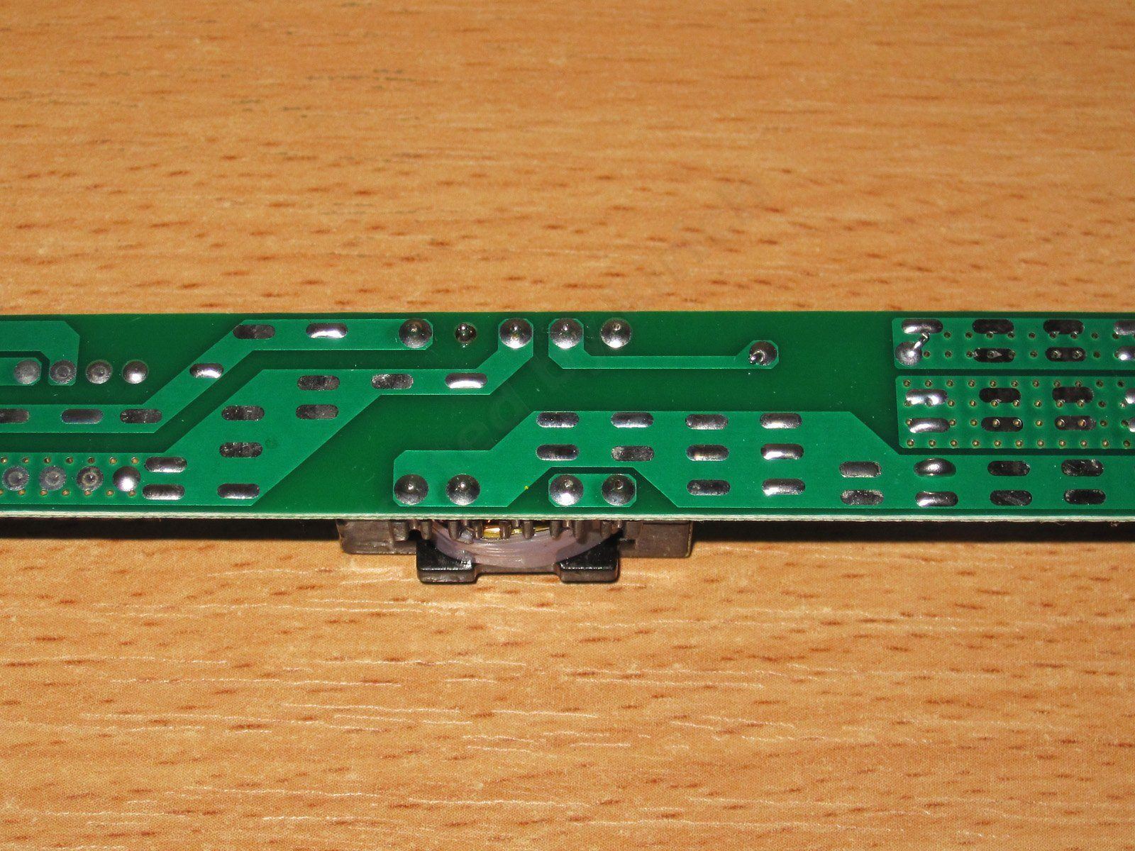
As far as electrical safety goes, it’s basically fine, though I’d like to see either more clearance or some isolation slots. Still, I’d give it a passing grade. It also helps that there’s no optocoupler in the feedback circuit, since routing traces to the feedback section as well can be awkward on a narrow board.
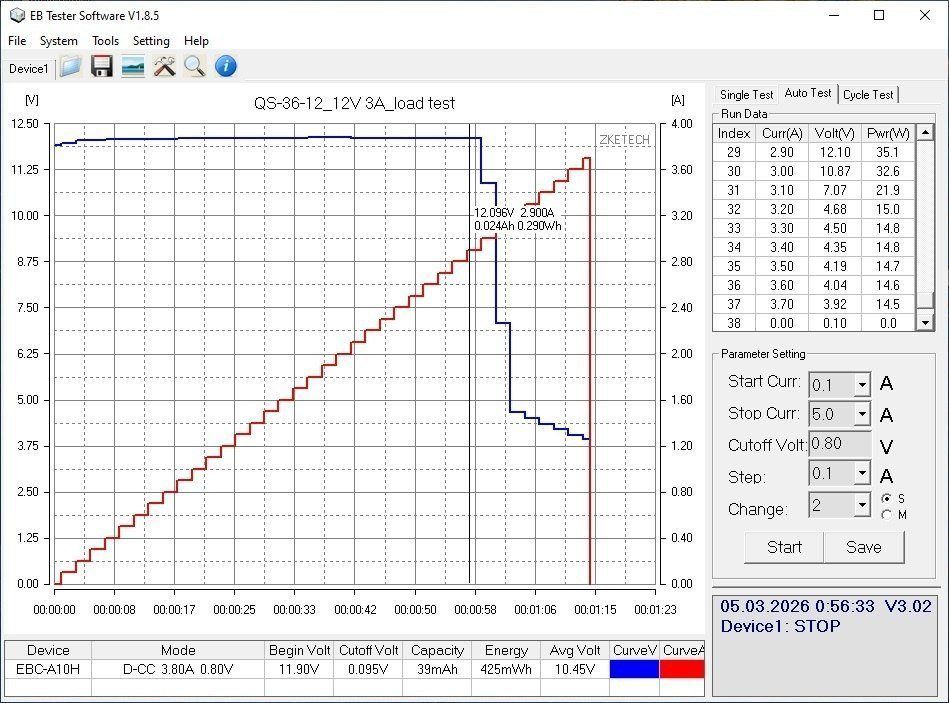
Under load, I got a maximum of 2.9 A. Beyond that, the voltage started dropping sharply, so the maximum power was around 35 W.
The power supply also has a noticeable positive load regulation: the output voltage rises from 11.9 V to 12.1 V as the load increases.
With no load, the output is 11.9 V and power consumption is 0.7 W, of which around 0.6 W is dissipated by the ballast resistors. So much for “green mode.”
I measured efficiency from 0.3 A to 2.9 A in 0.3 A increments. At the very end, instead of another 0.3 A, I increased the current by just 0.2 A to reach the maximum of 2.9 A. Efficiency came out to 84–85%, which is a bit low considering the synchronous rectifier on the output. I also got the impression that the power supply is “overclocked,” i.e. its actual rated power is lower.
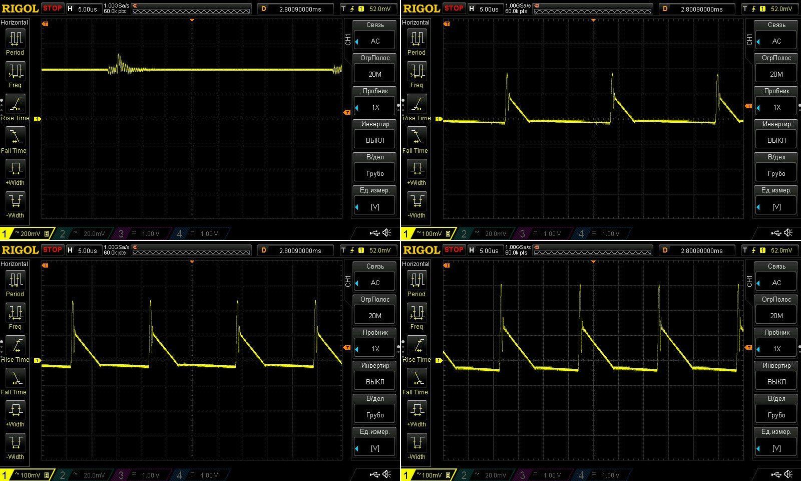
Ripple with no load and at currents of 0.9, 1.8 and 2.8 A. Nothing to complain about at high frequencies: these are typical results for budget models, with most of the ripple below 200 mV and a maximum of 350 mV. Overall, no complaints, though I didn’t like the no-load waveform.
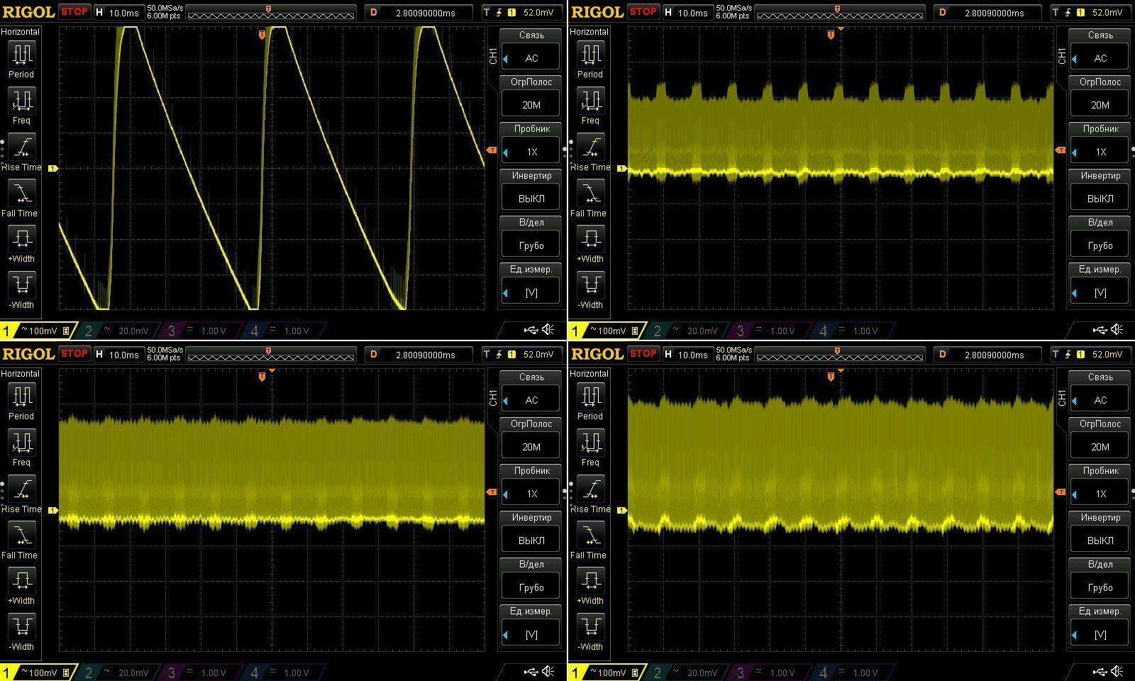
At low frequencies, though, we can see what the designer was trying to deal with: with no load, the output swings by about 1.8–2 V. I suspect this is a quirk of how “green mode” works... Under load, everything is basically fine and behaves as expected.
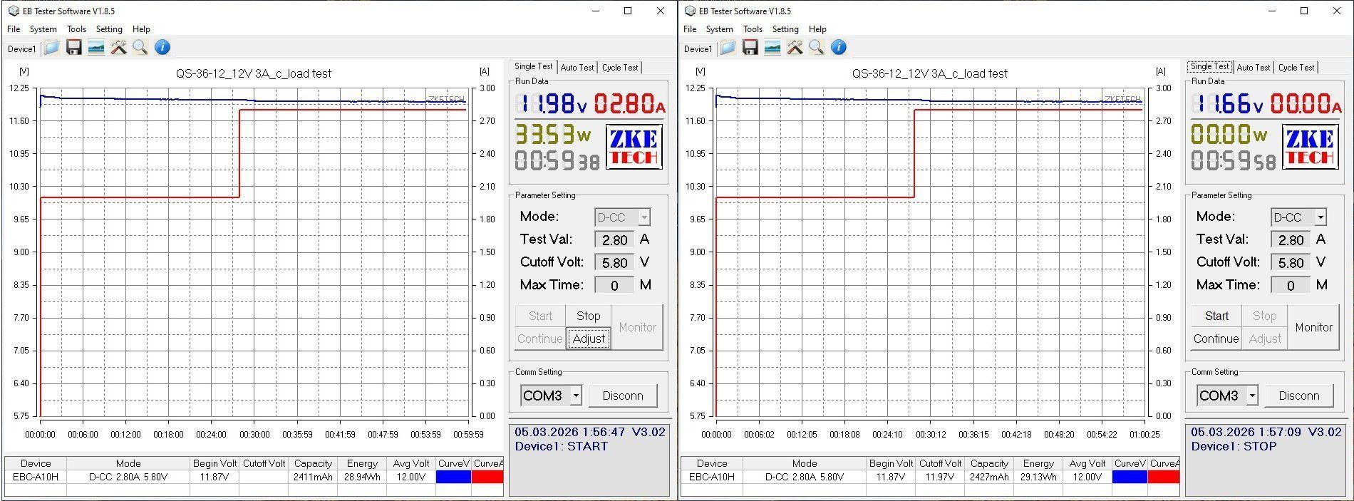
I tested the power supply under load in two modes, at 2 A and 2.8 A, for about an hour in total.
As it warmed up, the output voltage dropped slightly, from 11.87 V to 11.66 V.
And, of course, here are the temperatures in the tested modes.
2 A: transformer 69 °C, PWM controller 64 °C, rectifier 63 °C.
2.8 A: transformer 89 °C, PWM controller 75 °C, rectifier 95 °C.
Here we can see that the transformer has reached its maximum operating point, just as expected, so our estimate of its power rating was right. The PWM controller temperature was a bit surprising, though. It’s probably rated for the same 24 W as the previous model; perhaps the “24” at the end of the part number and the 2.9 A protection current are clues. Still, it works quite well: 75 °C at maximum power is fine.
I wouldn’t say the output synchronous rectifier gets particularly hot either; 95 °C is perfectly normal. I’m just a little concerned about that 40 V rating—it seems suspicious.
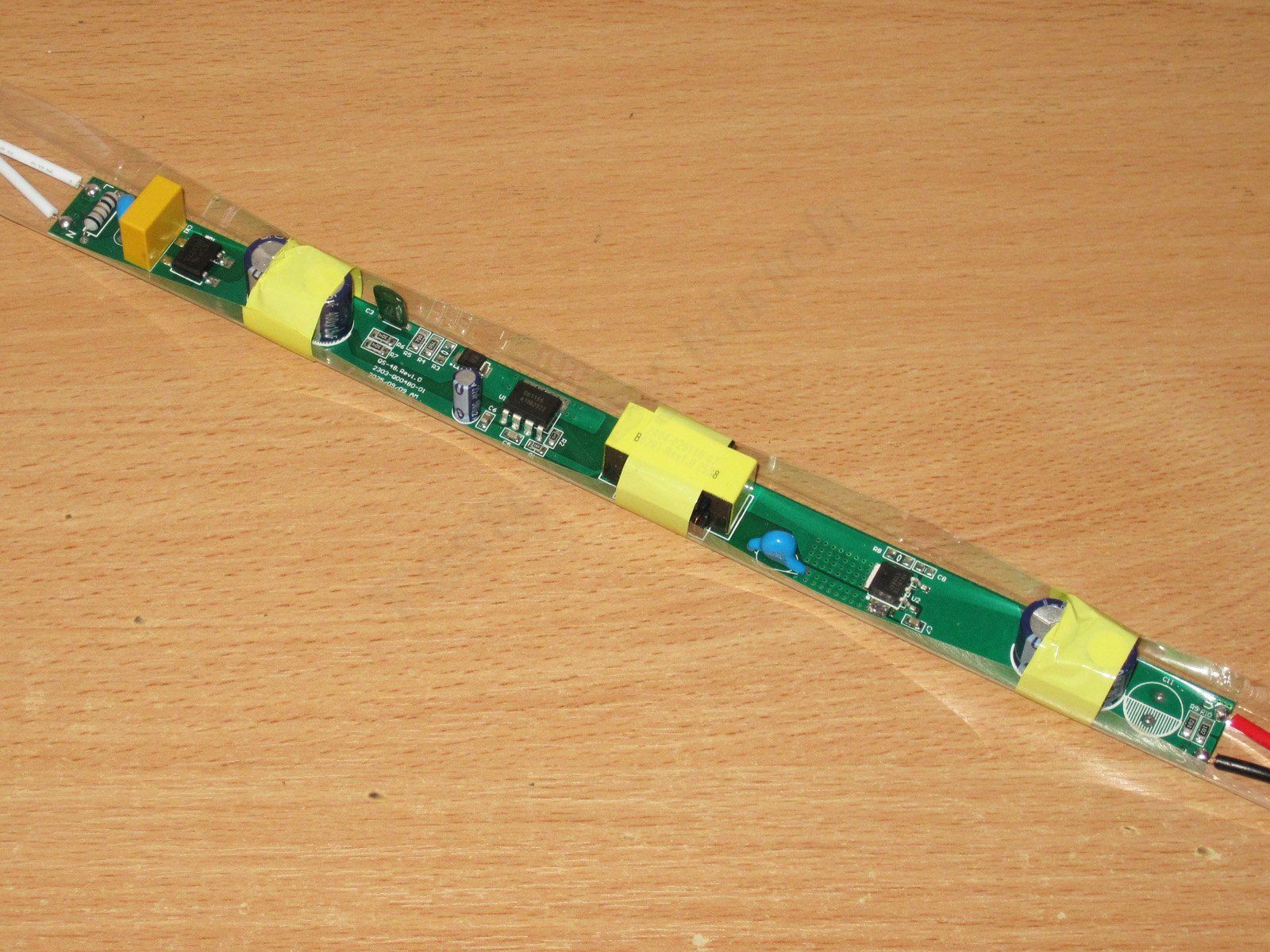
QS-48-12 model, 48 W, 4 A.
It looks just as neat, but even at a quick glance I noticed some similarities to the previous power supply.
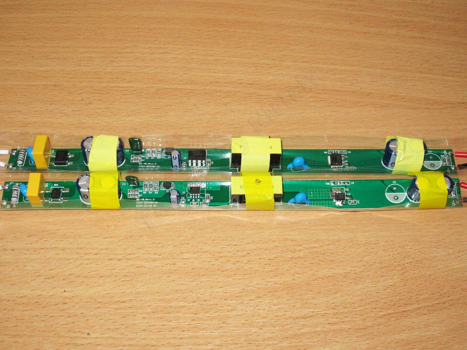
And sure enough, they’re basically twins, apart from a few minor differences. The input and output each have a pair of capacitors, too, which means there’s only 18–19 µF here for 48 W—really poor.
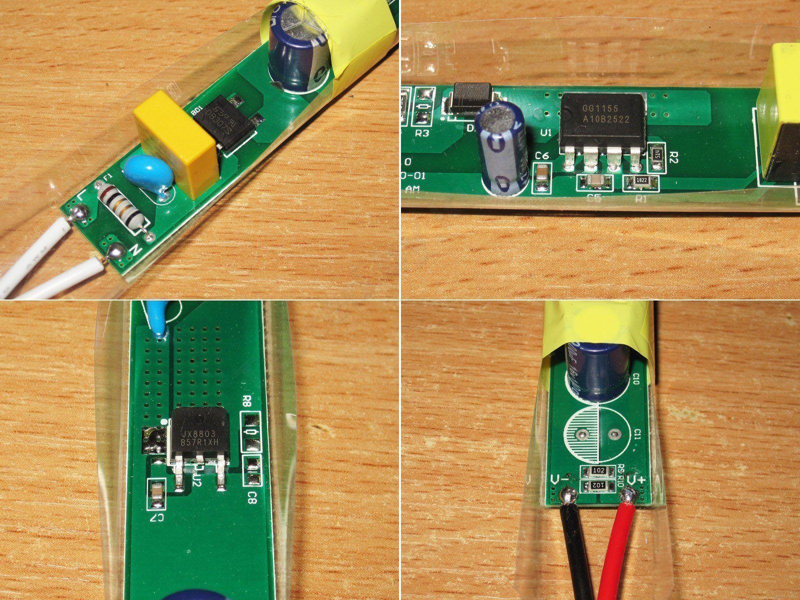
1. They fitted a larger bridge rectifier: 3 A, 700 V instead of 2 A, 1000 V.
2. The PWM controller is a GG1155. It’s also clear that the board was designed to be universal, but, as before, I couldn’t find a datasheet.
3. The JX8803 synchronous rectifier also looks more powerful, and the board has a universal footprint for it as well. There’s no information on its specifications.
4. On the output, there are the same two capacitors, but first, they’re shifted over by one position because the board is designed for three shunts, and second, the ballast resistors are now the more familiar 1 kΩ. So, with a different PWM controller, the battle against “green mode” is over.
Preliminary testing showed that the actual output current tops out at just 3.6 A; beyond that, the voltage drops and the unit shuts down.
So, even at this stage, I can say that increasing the input capacitance would make this a perfectly honest 36 W power supply, but definitely not a 48 W one.
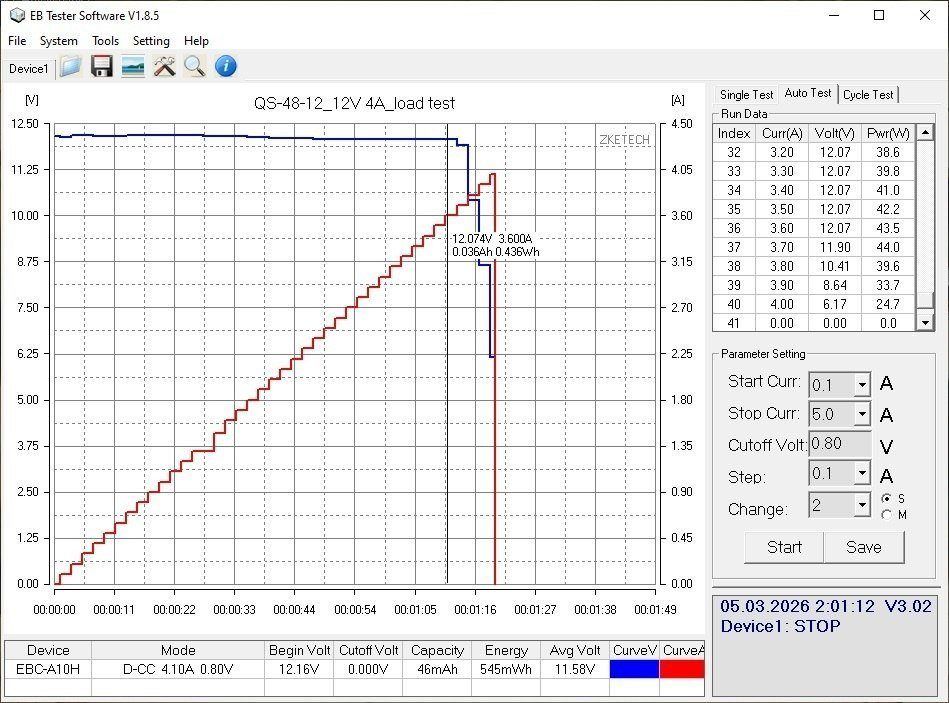
The no-load output voltage is 12.14 V, and power consumption is 0.55 W.
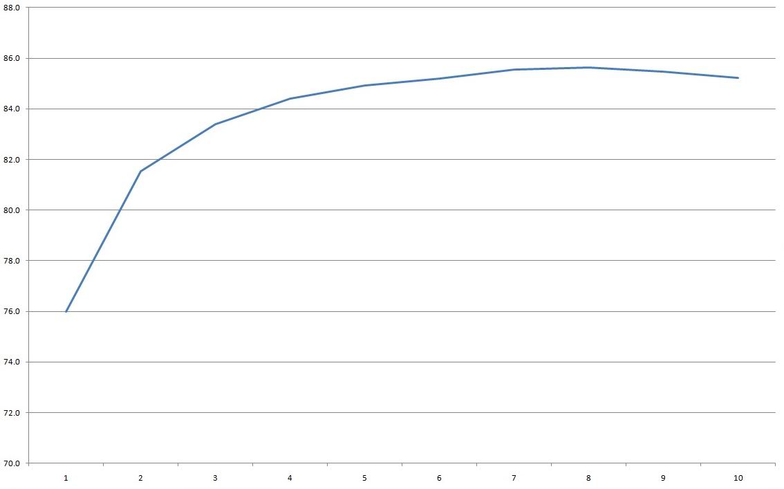
I measured efficiency from 0.4 to 3.6 A in 0.4 A increments, though I did manage to push the final step to 3.7 A. Overall, I got the same usual 84–85%, which is again a bit low for a power supply with synchronous rectification on the output.
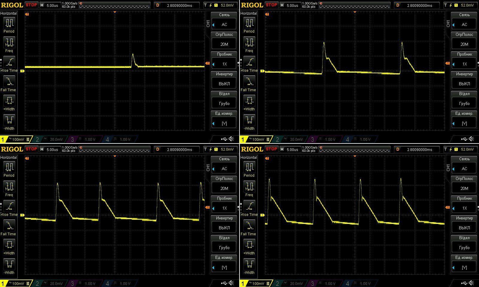
Ripple at no load and at currents of 1.2, 2.4, and 3.6 A is actually a little better than I expected. At 3.6 A, the total ripple is 300 mV, with the main component at 200 mV. Sure, you could say it can be much better, and I agree, but there’s no output filter here at all. There’s room for a polymer capacitor, though—and it would be even better to put it first, followed by a pair of the original standard capacitors. By the way, I should run some comparative tests with polymer capacitors sometime.
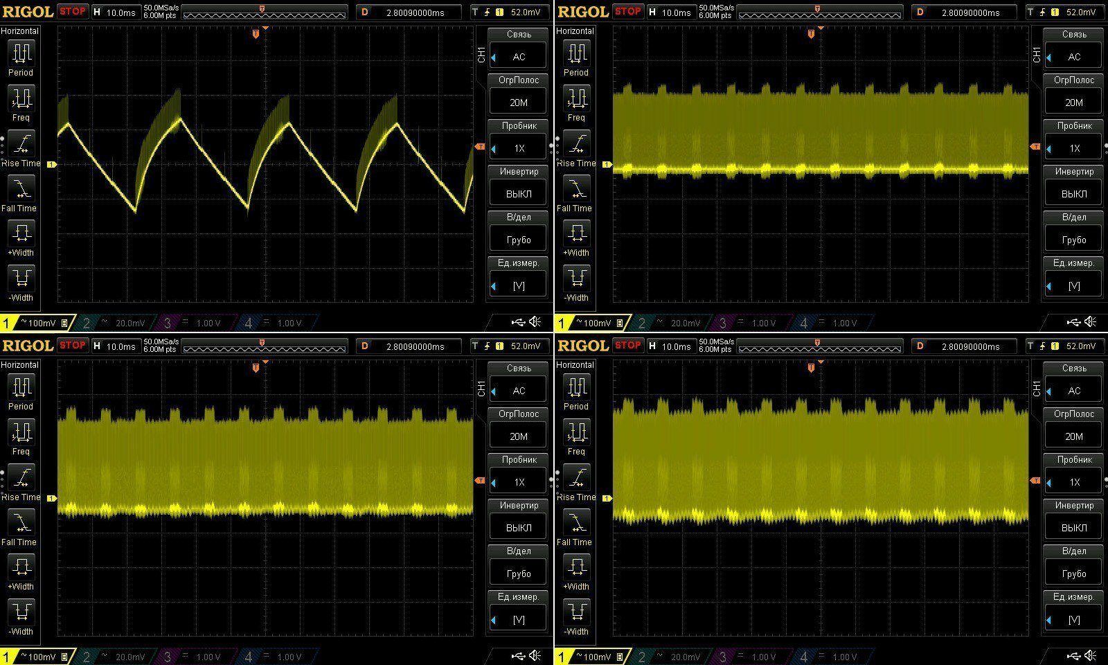
At low frequency, we can see “green mode” in action with no load, and the ripple is quite acceptable. The 100 Hz component is still noticeable, but judging by its shape, it could also be a feature of how the PWM controller operates. In any case, I have no complaints.
Now for the most interesting part: how does it handle a sustained load?
I tested it in three modes, at 2.5, 3, and 3.5 A. To start with, the voltage barely depends on temperature, and I wouldn’t say it depends much on the load either: at maximum current, it dropped by 0.1 V, which is very good for a power supply with primary-side regulation.
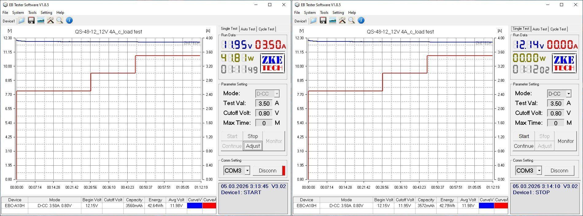
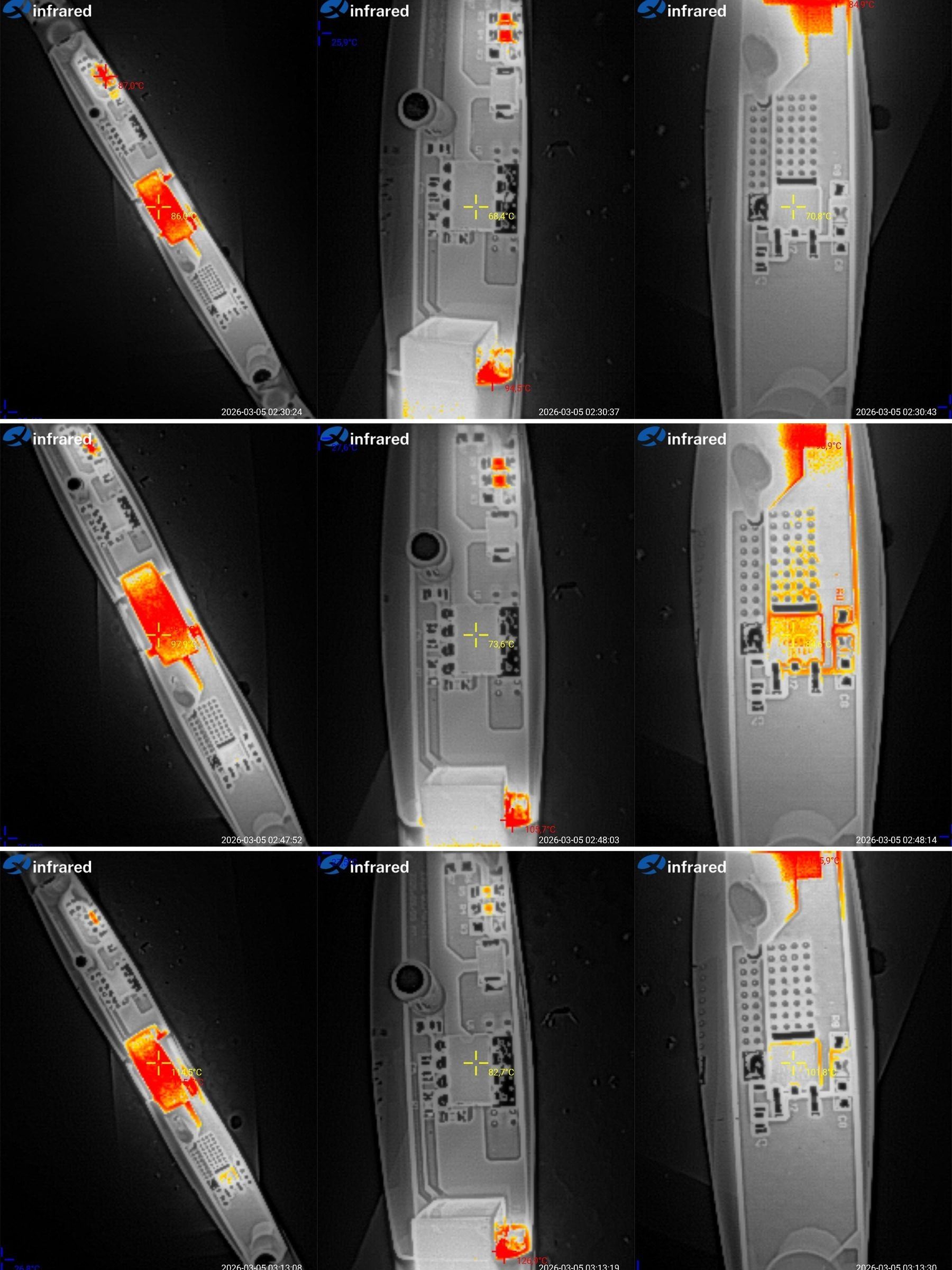
And now for the temperatures:
2.5 A — transformer 86°C, PWM controller 68°C, output rectifier 71°C. Still fine.
3 A — transformer 98°C, PWM controller 74°C, rectifier 85°C. You can already feel that the transformer is at its limit.
3.5 A — transformer 115°C, PWM controller 83°C, rectifier 102°C.
Well, as I wrote above, the transformers are rated for 30–35 W, which is exactly what we’re seeing. The PWM controller doesn’t get very hot, and the synchronous rectifier runs at a moderate temperature. So my opinion hasn’t changed: this is a power supply that can really deliver its stated 36 W, and 30 W continuously.
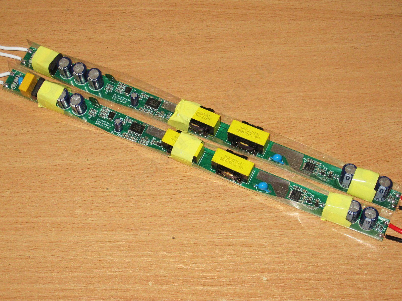
And the last pair: QS-60-12 and QS-72-12, rated at 60 and 72 W, and 5 and 6 A, respectively.
I’ve put them together because visually they’re the same power supply.
These models have two transformers instead of one, so there’s some hope they’ll manage their rated power. As with the previous models, the layout is relatively spacious, with large copper pours around the output rectifier.
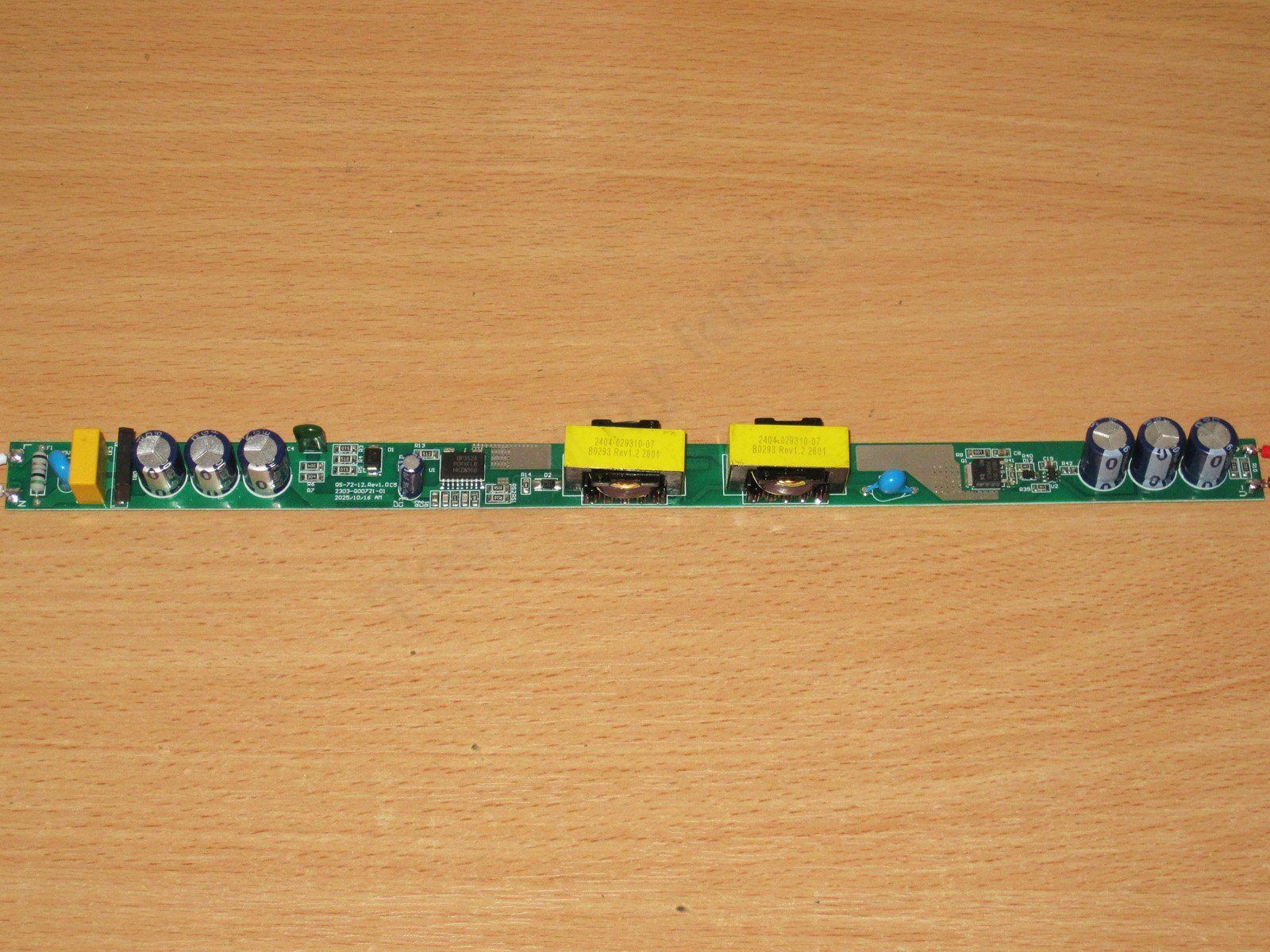
1. At the input: a resistor instead of a fuse, a varistor, an X capacitor, and a 4 A, 1000 V bridge rectifier.
2. There are three capacitors, giving a total capacitance of about 27–28 µF, which is just as low as on the previous models.
3. A pair of neat transformers.
4. A Y capacitor, with no issues here.
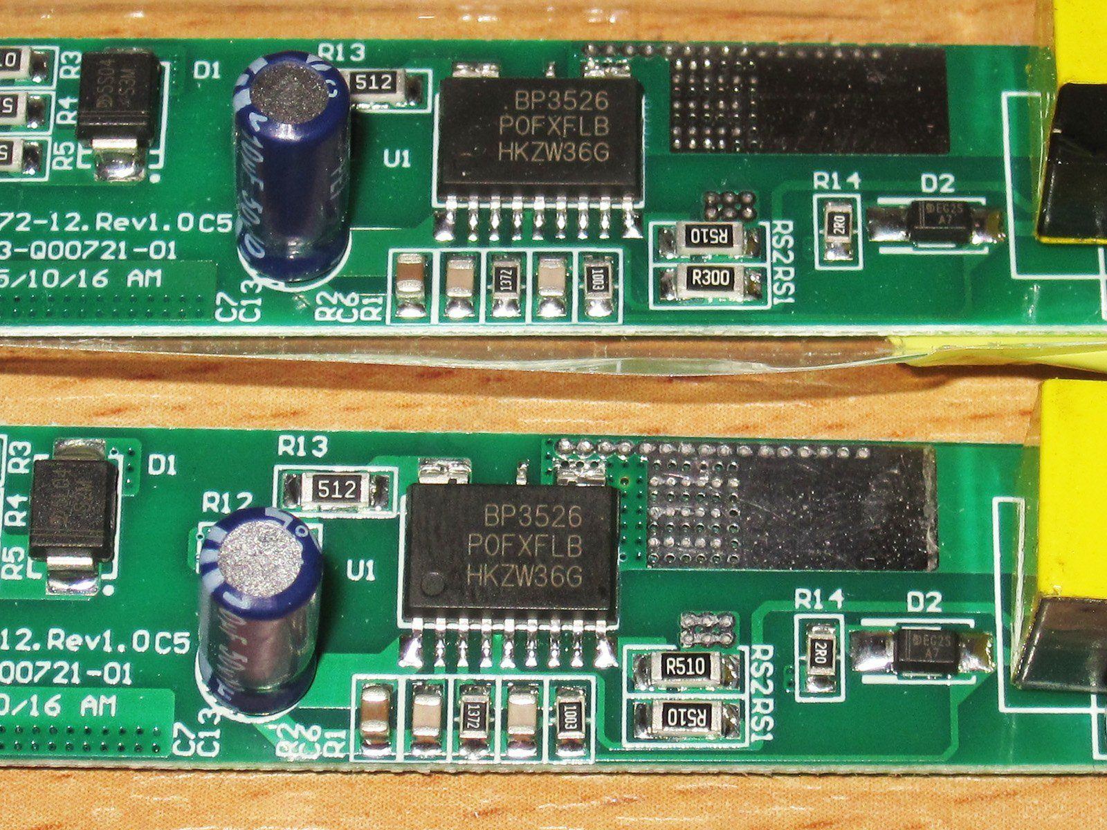
5. The output synchronous rectifier uses a controller paired with a separate MOSFET.
6. There are three output capacitors, the same type as on almost all the previous models, except the 24 W version.
Despite their similar appearance, there is one difference between the power supplies. The 72 W model is at the top, and the 60 W model is at the bottom. The difference is the value of one of the shunts: the 60 W model has 0.51 + 0.51 Ω, while the 72 W model has 0.51 + 0.3 Ω. That’s the only difference between these power supplies.
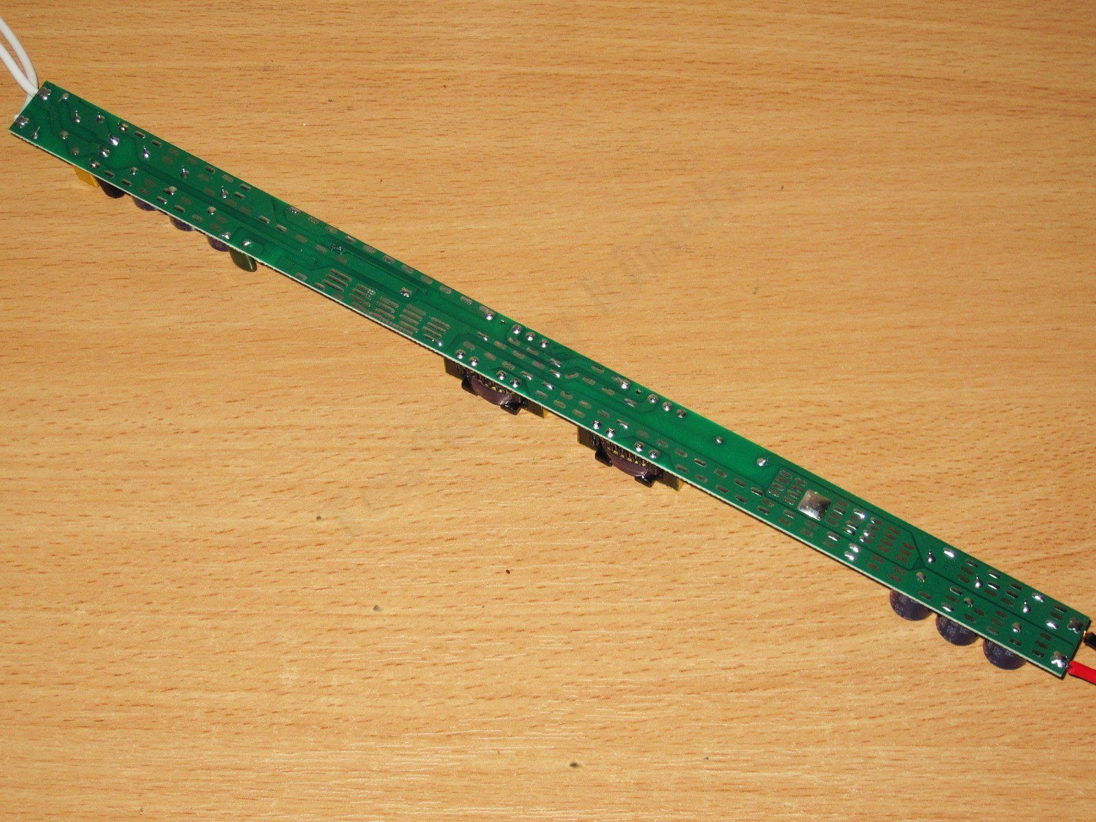
There are lots of large copper pours on the underside of the board, especially around the PWM controller and output rectifier. Here, the pours partly act as a heatsink, which is perfectly normal practice.
The electrical safety situation is far from ideal, but definitely better than on the 24 W model, which was a complete mess. If I were to pot this power supply, I’d say that was a good idea. In this case, though, I’d say it’s just about acceptable. As you can see in the photo, the clearance between the hot and cold sides isn’t as large as recommended, and there are no isolation slots. That said, adding them could easily break the board—it already bends in your hands. Speaking of the boards, it looks like they use thinner PCB material than the usual 1.6 mm, perhaps 1.2 mm.
The preliminary test was carried out separately on the two power supplies, and both graphs show the same characteristic behavior: as the load current increases, the output voltage first drops, then rises, and then drops again, forming a characteristic “hump.” It’s neither good nor bad—it just is what it is.
The 5 A model’s protection trips at around 6.5 A, while the 6 A model trips closer to 8.5 A. I also marked on the graph the voltage each power supply delivers at its rated 5 A and 6 A.
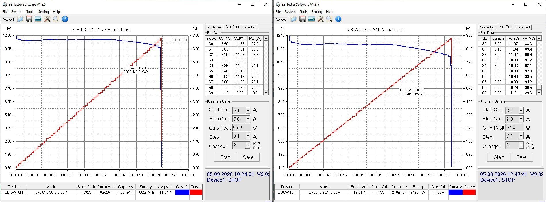
The no-load voltage is about 11.9 V, and power consumption is 0.5 W.
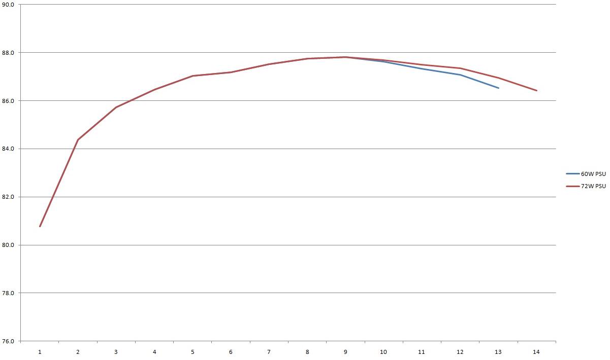
Efficiency was measured from 0.5 to 6.5 A for the 60 W model and from 0.5 to 7 A for the 72 W model, in 0.5 A increments.
That’s because I originally planned to measure only the 60 W model, since they’re essentially the same. But there’s a catch: the output voltage of the 60 W model starts to drop a little earlier than that of the 72 W model. For example, at 6.5 A, it’s 11.15 V and 11.31 V, respectively.
So here’s the resulting graph, showing both models. Up to and including 4.5 A, the graph is for the 60 W model only; beyond that, it splits into the 60 W and 72 W versions.
Efficiency came in at around 87%, higher than all the previous models, which gives me some hope that it’ll run cooler.
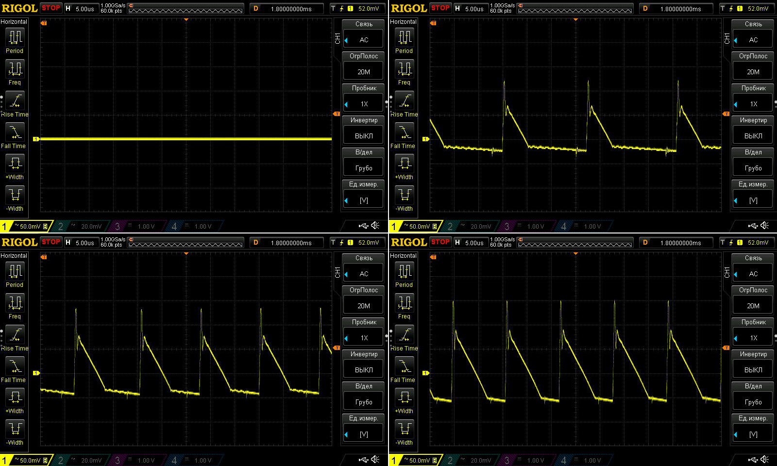
Ripple at no load and at currents of 2, 4, and 6 A.
To be honest, these power supplies surprised me a bit. At maximum current, I measured just 200 mV peak-to-peak, with the main component even lower, at around 150 mV. Considering this is a conventional flyback power supply with no output filter and no polymer capacitors, I’d say that’s a very good result.
Yes, I still think that replacing one of the capacitors with a polymer one would reduce ripple further and extend the service life, but even as it is, I think it’s pretty good.
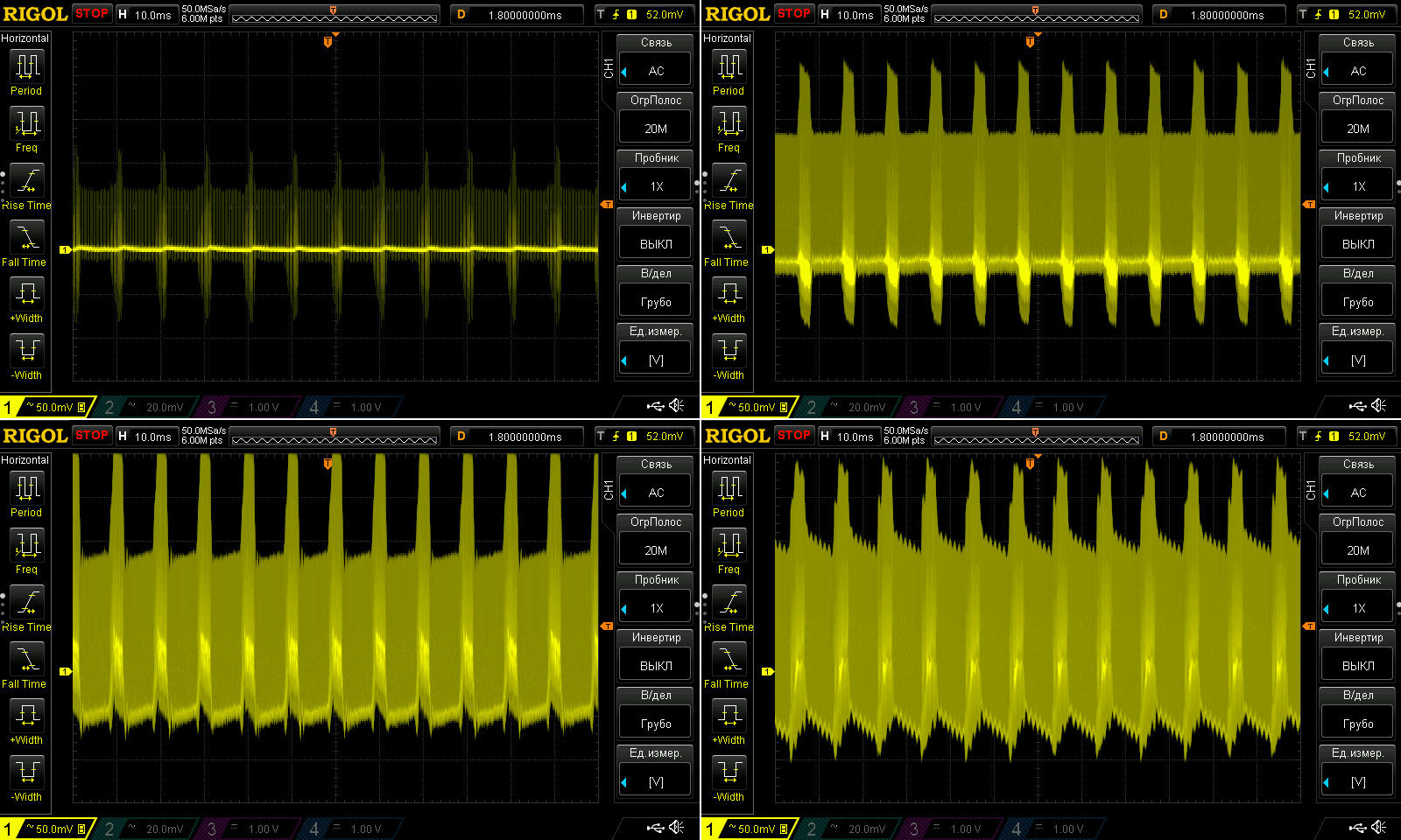
I was just about to celebrate finally finding a great power supply when I switched the oscilloscope to a different timebase to check the 100 Hz ripple—and got a “surprise”: the results were dramatically different from the high-frequency ripple.
Yes, it all looks very messy. It seems to be some kind of quirk of either the PWM controller or the PCB layout, because even with 27 µF of capacitance, it’s hard to get this kind of result at a load current of just 2 A.
You can also see that the ripple was highest at 4 A. But is that bad for the load? Not really, especially if the load is an LED strip installed inside an advertising sign.
The point is that even at 4 A, the peak-to-peak ripple is about 350 mV, and the 100 Hz spikes have an even smaller amplitude, so it just looks scary. For the previous power supplies, I measured ripple at 100 and 200 mV per division; here, the scope is set to 50 mV per division. If I switch to a higher voltage range, everything looks much cleaner.
Naturally, I wouldn’t use this power supply for sensitive loads, especially audio amplifiers. Though I’d be very curious to meet someone who’d even think of doing that :)))))
The load test was carried out in four stages, at 3, 4, 5, and 6 A. I tested only one power supply, since I’m almost certain the results for the other one would be identical.
The load caused the voltage to drop by about 0.6 V, which is quite a lot, though still acceptable. Heating raised the voltage by just 50 mV.
Perhaps it also mattered that this was the 5 A model running at a 6 A load. I’d also noticed earlier that its output voltage starts to drop sooner than that of the 6 A version. In my notes, with the power supplies cold, the voltage at 6 A was 11.32 V and 11.5 V for the 60 W and 72 W units, respectively, so this drop may be due more to the way the protection circuit works.
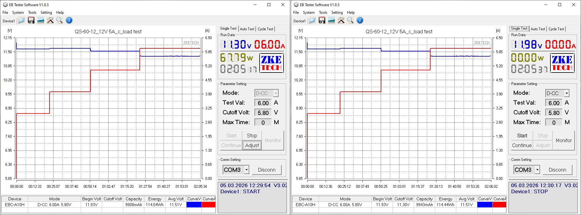
And now for the temperatures. Here are the results at the same currents: 3, 4, 5 and 6 A.
At 3 and 4 A, there isn't much to comment on: nothing is overheating, and all the temperatures are within the normal range.
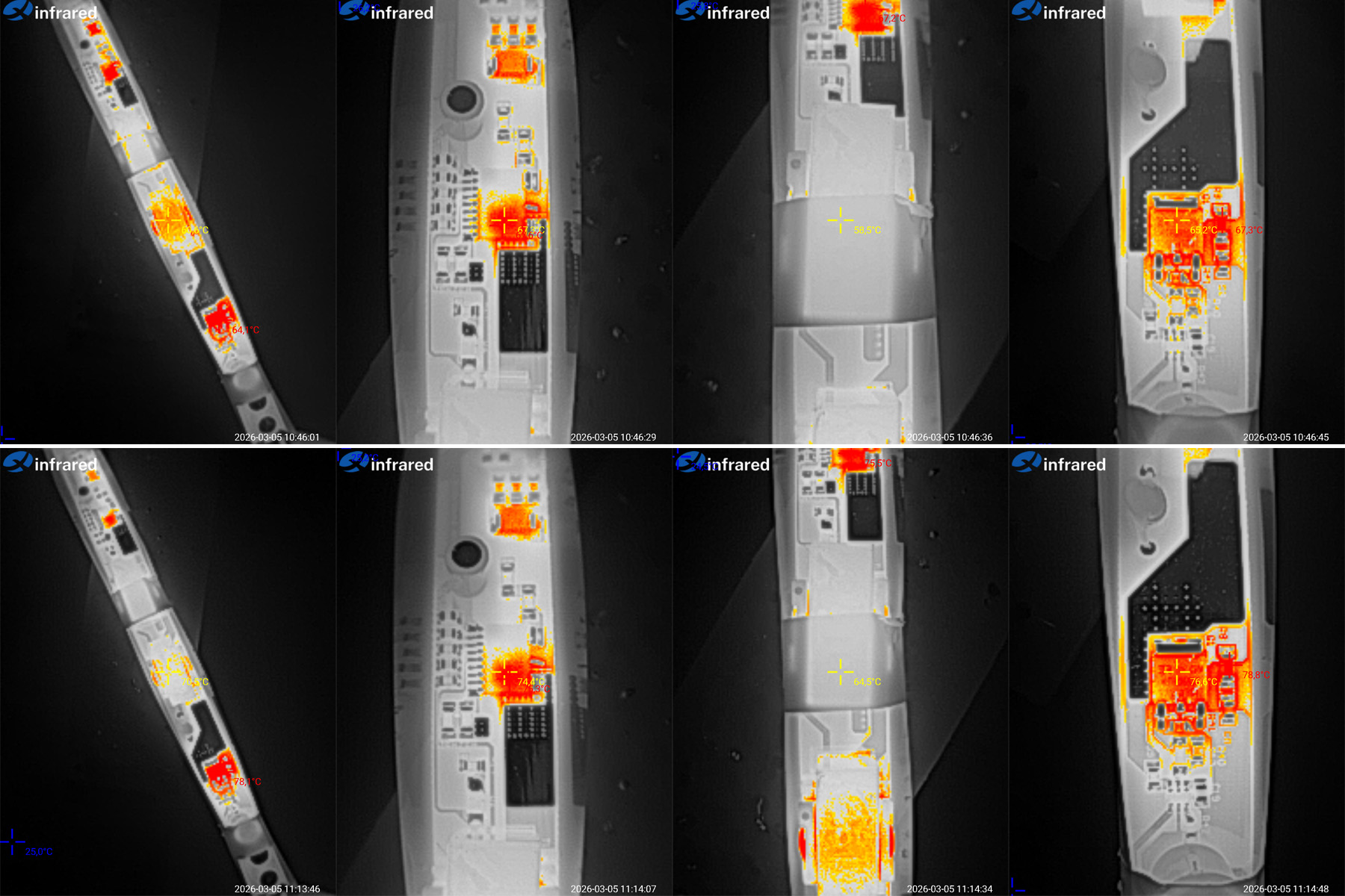
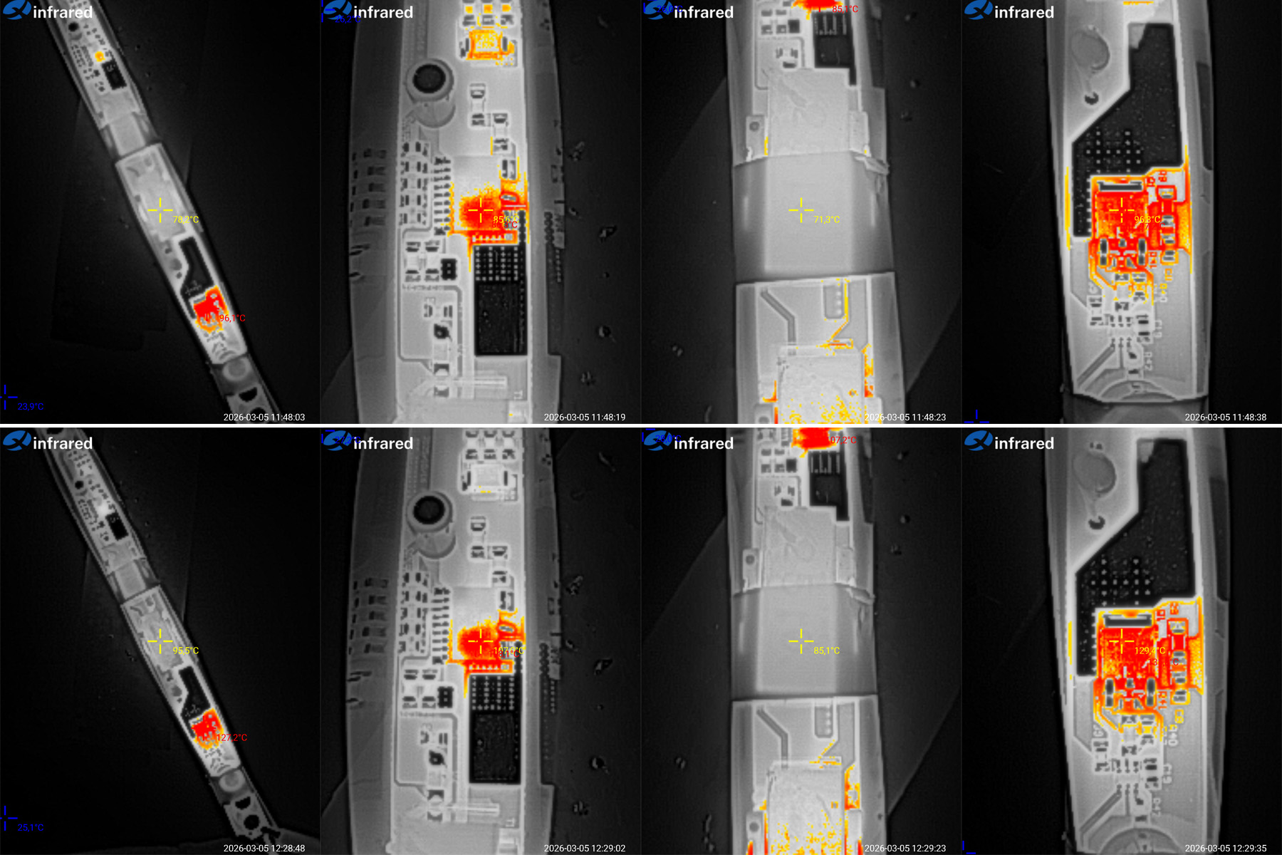
At 5 and 6 A, things get more interesting, especially since these are the maximum currents for the 60 W and 72 W power supplies.
At 5 A: transformers at 78 and 71 °C, PWM controller at 86 °C, output rectifier at 97 °C.
At 6 A: transformers at 96 and 85 °C, PWM controller at 108 °C, output rectifier at 130 °C.
It's interesting how much the relatively small increase in current from 5 to 6 A affected the temperatures. Sure, the board had also warmed up by then, but the difference is still significant: the results went from “moderate” to “we're overheating.”
At 6 A, almost everything started overheating: one of the transformers—the one closer to the output rectifier, which was probably heating it up—the output rectifier itself, and the PWM controller.
In short, 6 A is way too much for this unit. 5 A is the maximum, and probably closer to 4.5 A. Maybe filling it all with
Conclusions.
QS-18-12 — Overall, a decent power supply. The transformer has a twofold safety margin, the protection threshold is fine, ripple is acceptable, and I have no complaints about the board's safety. However, the chip is rated for 12 W, and there's an ordinary capacitor in place of a Y capacitor.
LF-CBB24-2A — So-so. Incidentally, this is the only power supply with feedback from the output. My concerns are about the safety of the PCB layout, the interwinding capacitor, and the output diodes getting very hot. I have no real complaints about the transformer, which has plenty of headroom, or the relatively decent PWM controller. But the key issue is poor electrical safety; otherwise, it's reasonably acceptable.
QS-36-12 — A decent power supply in principle, except that its actual power is probably 30 W: protection kicks in at 35 W. On the other hand, that does make it harder to burn out. I do have serious concerns about the high ripple with no load, though in the application it was designed for, that situation is unlikely to occur.
QS-48-12 — A more powerful version of the previous model, with some components replaced. That would be a good thing if not for a few issues: the transformer overheats, and the protection current is set to around 3.5 A rather than 4 A. Overall, this is more like a properly rated QS-36-12 than a QS-48-12.
QS-60-12 and QS-72-12 — Relatively decent models, provided you bear in mind that they're actually the same power supply, and that in reality it's no more than a 60 W unit—possibly 50 W, and certainly not 72 W. There is one electrical safety issue that I think the manufacturer could at least reduce, if not fix outright.
Basically, the rated specs of almost all the models are one step too high. For example, if the 48 W model were labeled as 36 W, everything would make sense.
A note that applies to all the models: I personally didn't like that the input capacitors are undersized to some degree in every model. It works, but this usually affects service life and startup at subzero temperatures. Also, for models with space for more than one output capacitor, I'd like to see at least one polymer capacitor. That would improve ripple and reliability.
That's all for today. I hope this was useful, and thanks to Vitaly for sending the samples for testing. As usual, I'd be glad to hear your comments and thoughts on these models.
Questions and answers
What is the actual power of the QS-18-12 to QS-72-12 power supplies?
The ratings of 18, 24, 36, 48, 60 and 72 W are overstated by roughly one step for many models. For example, the QS-48-12 protection trips at about 3.5 A, while the author considers the QS-60-12 and QS-72-12 essentially the same supply, rated at no more than about 60 W.
What did the QS-18-12 test show?
At a 1.5 A load, it delivered 12 V and had an efficiency of 85%; its protection tripped above 1.6 A. The author says its controller is more like a 12 W design and flags the 1 kV interwinding capacitor as a serious safety concern.
What problems were found in the 12 V power-supply bars?
All models have undersized input-capacitor capacitance; the QS-48-12 transformer overheats, and some models have protection thresholds below their stated ratings. The author also points out design-related electrical-safety concerns.
This model is included in the summary table: Comparison of power supplies: ripple, efficiency, and temperature rise
The figures from this review are in the measurement database: Power supplies
Discounted products
You may be interested in



Discounted products
All the content on the site and the advice are free, but we’d be grateful for your support of the project and the channel!
Comments2
Only registered readers can comment. It takes a minute to sign up, and you can log in with the same account you use on the forum.
Log inRegister
Comments are published in their original language.