
Riden RD6018P Hybrid Adjustable Converter
To keep up with new posts on the blog, I recommend following me on Instagram, where I'll post notifications about new articles and maybe write about something interesting too: link to my account
You can also subscribe to updates and new articles on the Telegram channel - https://t.me/KirichBlog
This review could have come out earlier. After I contacted the manager, he replied that he'd tried to message me as soon as the new model came out, but since we hadn't been in touch for a long time, AliExpress chat wouldn't let his message through. I happened to see the news about the new model by chance, and that's why I wanted to test it: I'd already had all the models in both the RD series and the other lines:
Here's a list of all the converters from this company that I've had a chance to try.
DPH5005
DPS8005
DPS5020
RD6006
RD6012
RD6018
RD6006P
RD6012P
RD6024
RK6006
Enclosure and power supply for the RK6006
RD6030
Silicone case covers
RD 25A cable set
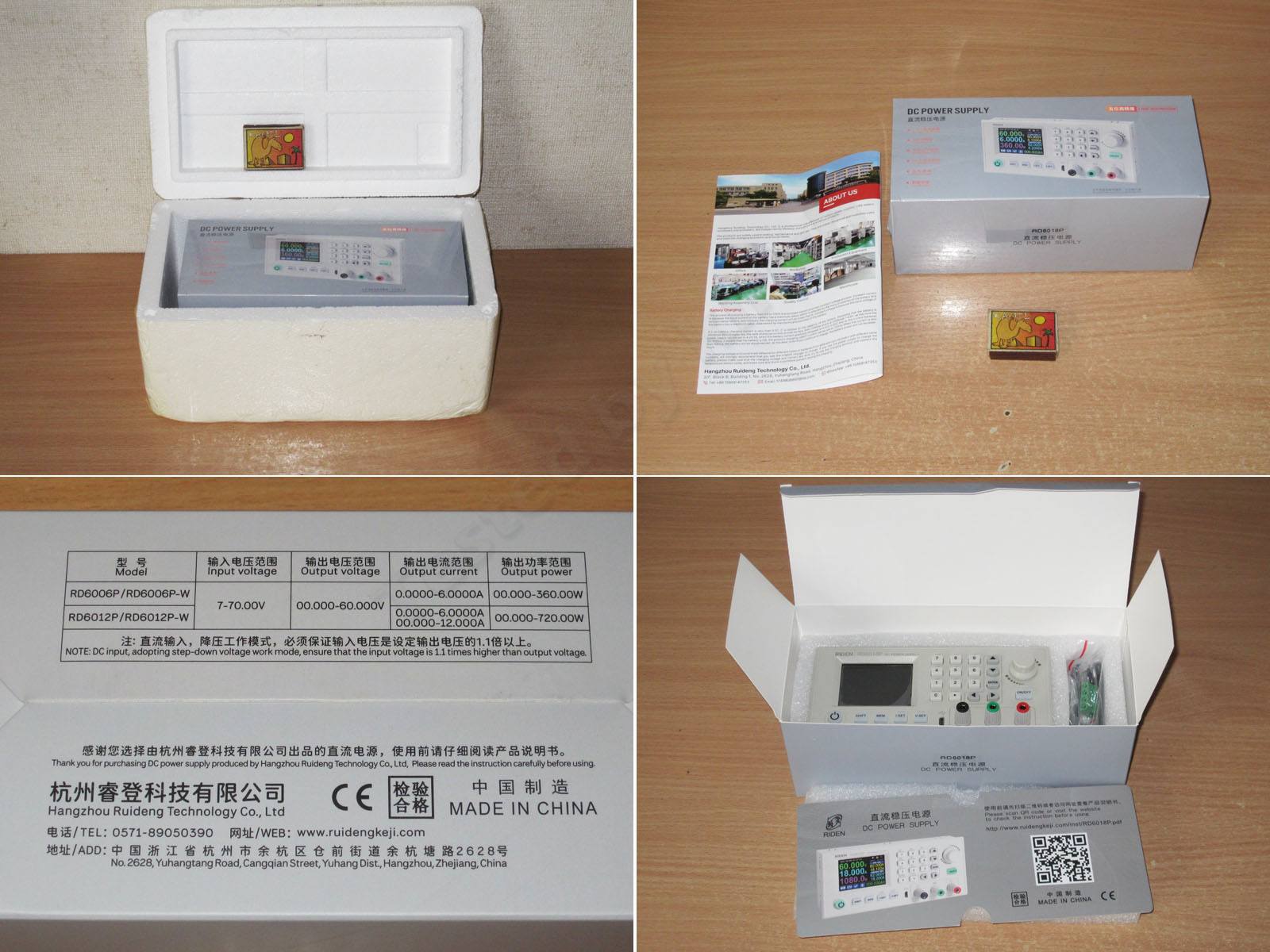
The packaging is as usual—hard to imagine anything more secure. Inside is a box with the converter and a brochure.
Two things stand out. First, the bottom of the box doesn't say RD6018P. Second, the manufacturer has simplified the box: it's now made of thin cardboard. But with the unit packed in foam, I don't think this makes any real difference.
A colorful brochure showcasing the company's current products.
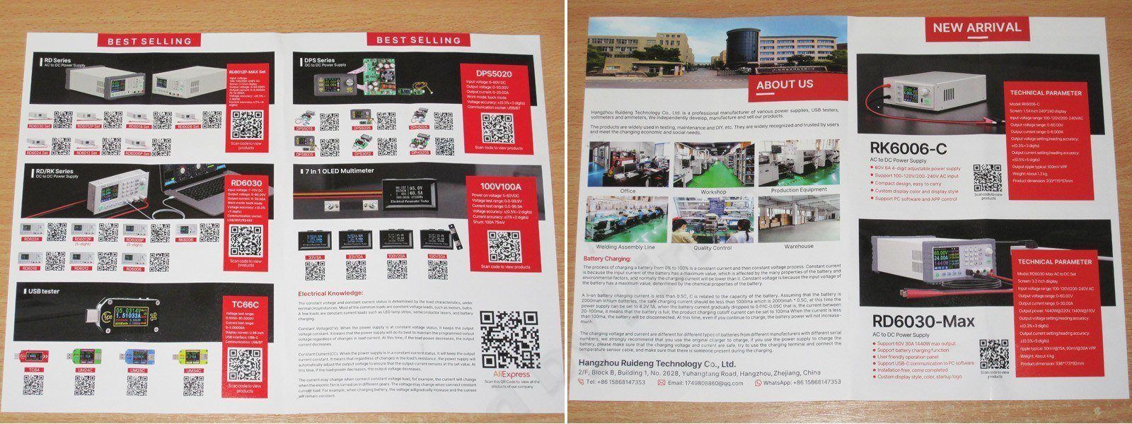
The brochure also shows what isn't exactly a new model, but is quite interesting.
The manufacturer has introduced the MAX series—or, more precisely, fully equipped versions of its products. The main feature is a larger display, increased from the standard 2.4 inches to 3.2 inches.
This version is available in three models: RD6030, RD6012P and RD6018P.
I wanted to get this version for the review, so I'd have both a new model and the larger display right away. But I was told that the larger display is only available on the MAX version, and the converters aren't sold separately.
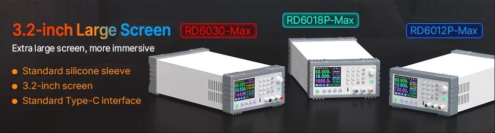
In fact, the differences aren't limited to the display: this version also comes with silicone covers and Type-C instead of the usual microUSB.
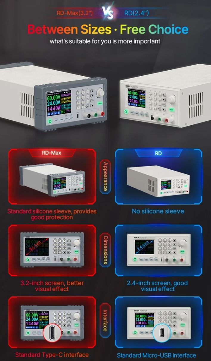
This is the basic package. I somehow forgot to order the WiFi version, though to be honest, I haven't used that feature once all this time; local control is usually enough..
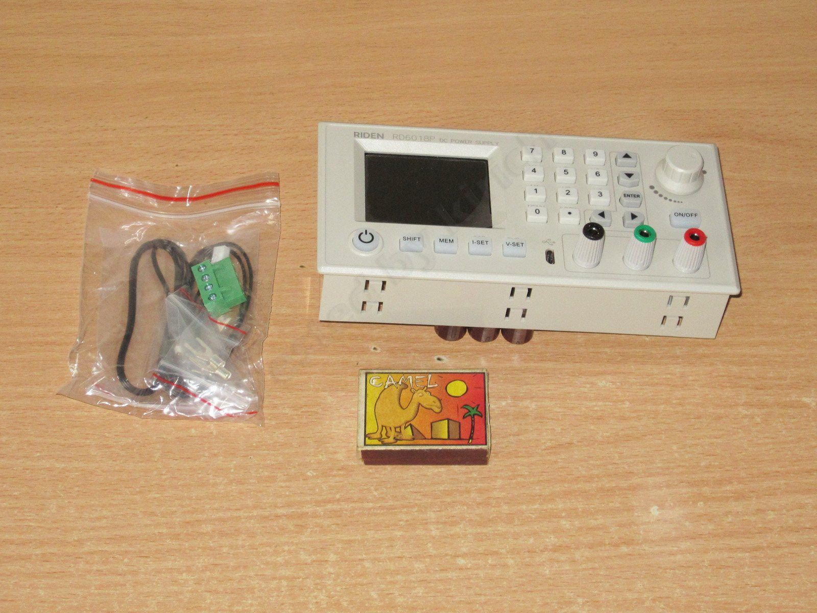
The package includes:.
1. The RD6016P converter itself
2. External temperature sensor
3. Terminal block for connecting the input power
4. A pair of cable lugs for the power cables
5. 25 A fuse.

There’s no point describing the appearance: the form factor and controls are exactly the same as before. The only difference is the model name.
In this respect, I have to give the manufacturer credit: when a new model comes out, you can replace the old one in just a couple of minutes.
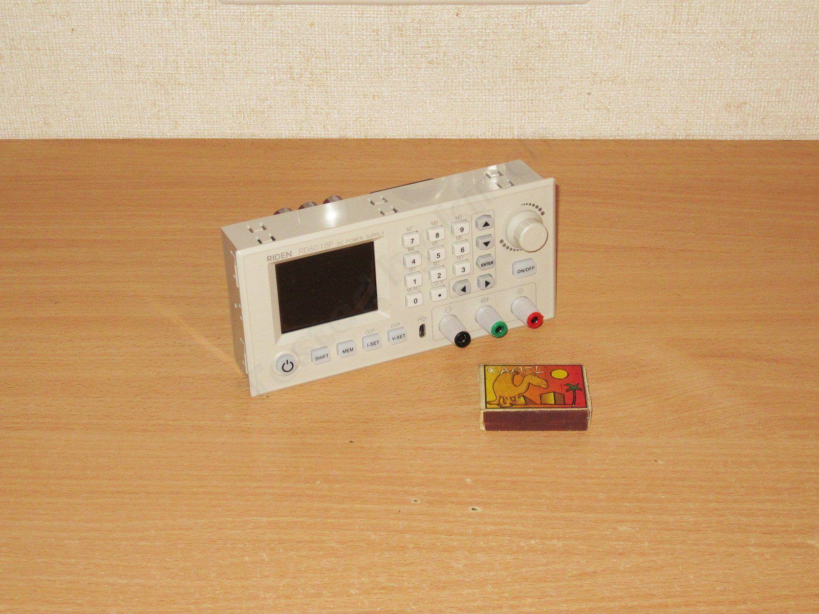
Specifications from the product page:
Model: RD6018P/RD6018P-W
Input voltage range: 7-70.000V
Output voltage range: 0-60.000V
Output current range: 0-18.000A
Output power range: 0-1080W
Output voltage resolution: 1mV
Output current: 1mA
Output voltage accuracy:0.05%+4mV
Output currentaccuracy:0.1%+6mA
Default cutoff current value when charging: 10mA
Output ripple typical: 20mV
Working temperature range: -10℃~40℃
External sensor Temperature detection range:-10℃~100℃/0℉~200℉
External sensor Temperature detection accuracy:±3℃/±6℉
Constant voltage moderesponse time: 22uS 0.5A-18A
Constant voltage mode load regulation: ±(0.1%+0.2mV)
Constant current mode load regulation: 0.1%+3mA
Capacity measurement range: 0-9999.99Ah
Energy measurement range: 0-9999.99Wh
Capacity and energy statistical error: ±2%
Buck working mode: (input voltage÷1.1)-1
Over temperature protection: System temperature>90℃
Screen brightness setting: 0-5(6 level in total)
Screen: 2.4 inch color HD display
Weight(with package):About 0.74kg
Product dimension: 167*81*67mm
Cooling fan start condition: Output current>6A or System temperature>45℃
Cooling fan shut down condition:Output current <5.9A and System temperature <40℃
The internals have changed, of course, although in simplified terms, the component ratings (current, power, capacity) have changed. Functionally and in terms of the circuit design, the converter is similar to the previous 6012P model.
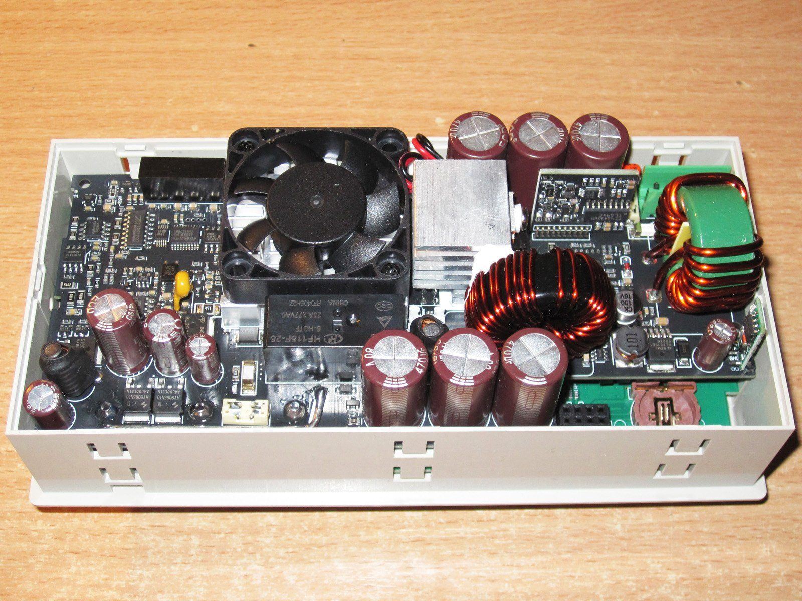
1. Input section: terminal block, fuse, space for a spare, and input capacitors.
2. There are three 470µF 80 V input capacitors connected in parallel.
3. The transistor on the large heatsink. At first I assumed it was part of the linear regulator, but disassembly and further analysis showed that it is one of the transistors in the DC-DC section.
4. The converter's PWM section. Below it, in the video, you can also see an LM324 op-amp and some other small components.
5. Auxiliary converter section.
6. Overvoltage protection section.
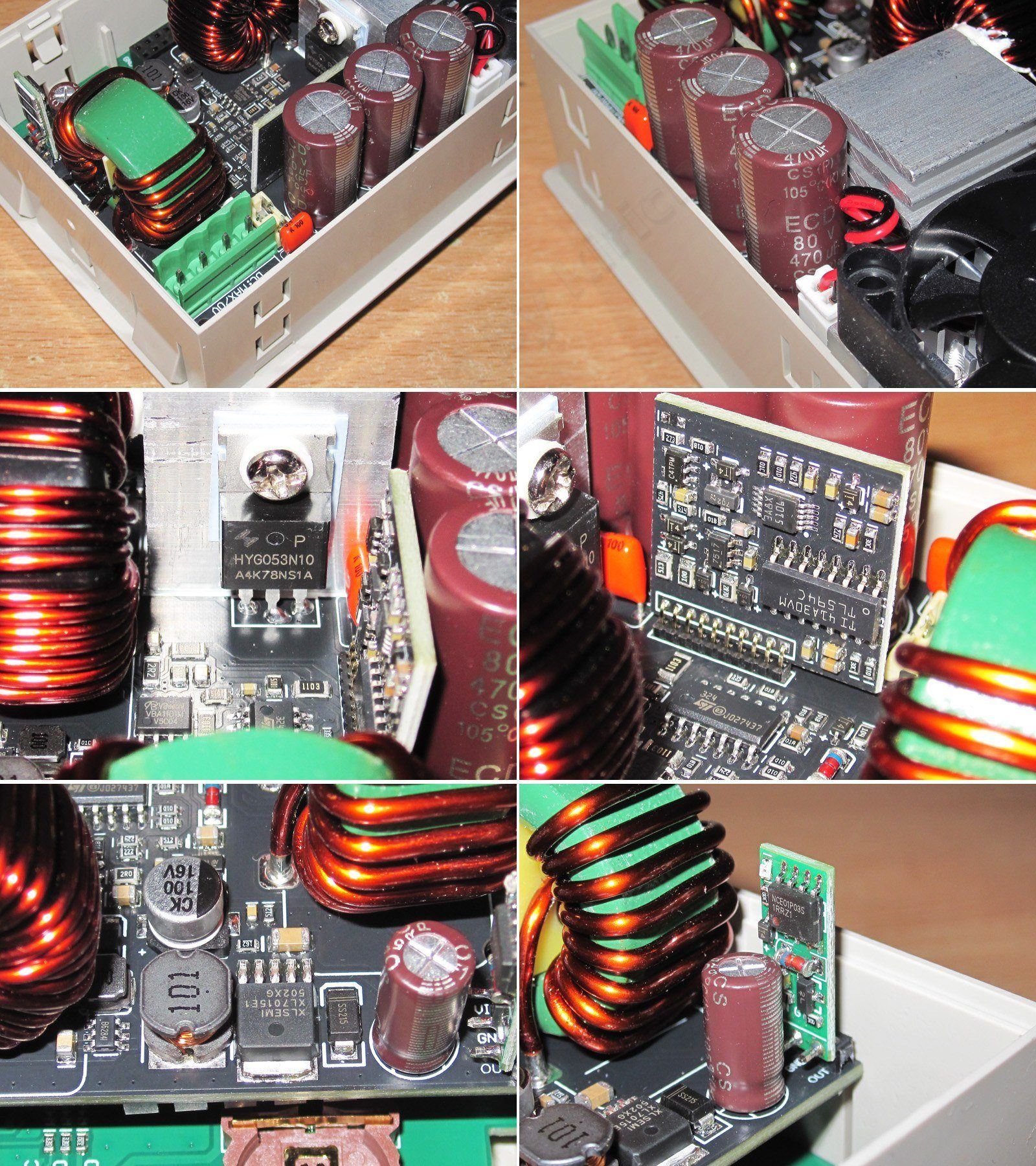
1. External temperature sensor connector. They really tucked it away well. Next to it is what appears to be the filter inductor after the DC-DC section.
2. The switching section output also has three 470µF 80 V capacitors.
3. Relay for connecting the battery in charging mode; judging by the markings, it is rated for 23 A.
4. Output fuse section, and most likely the output capacitor switching circuit as well. By the way, I noticed that the installed fuse is from LittleFuse, while the one included in the package is some other brand. This fuse protects the converter if you apply power to the output terminals with reversed polarity. There’s an LED next to it, connected in parallel with the fuse to indicate when it has blown.
5. Three capacitors: 22, 100, and 220µF. As I understand it, the 22µF capacitor is always connected, while the others are switched in depending on the output current—possibly +100µF above 6 A, and another +220µF above 12 A.
6. Transistors and output filter: an inductor and a 47µF capacitor.

The analog and digital section is hard to describe without a schematic. The only thing that’s clear is that there’s also an isolated DC-DC converter on the left.
In any case, it’s unlikely that anything here has changed compared with the 6012P model, and there’s no reason why it should have.
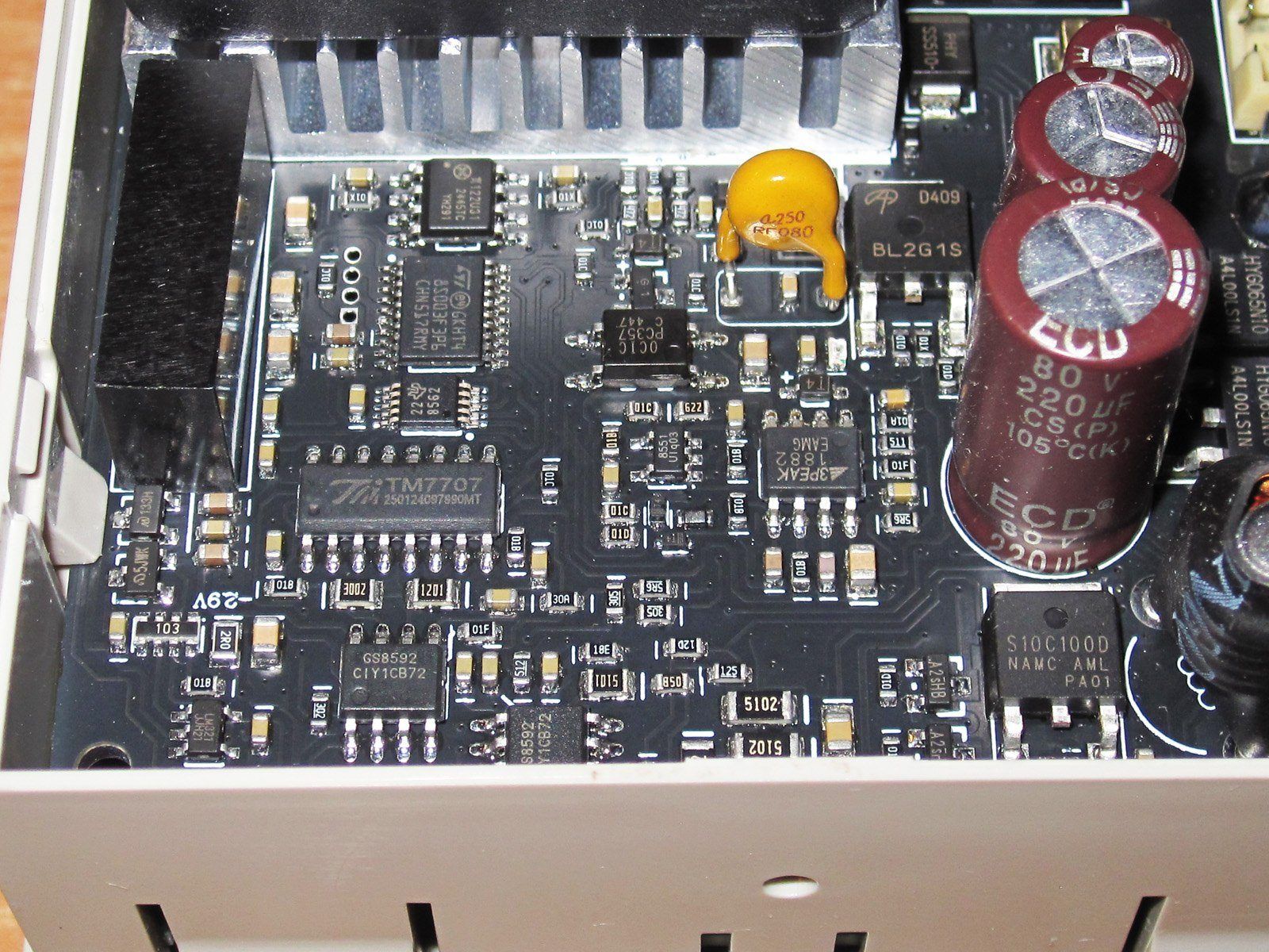
Just another angle.
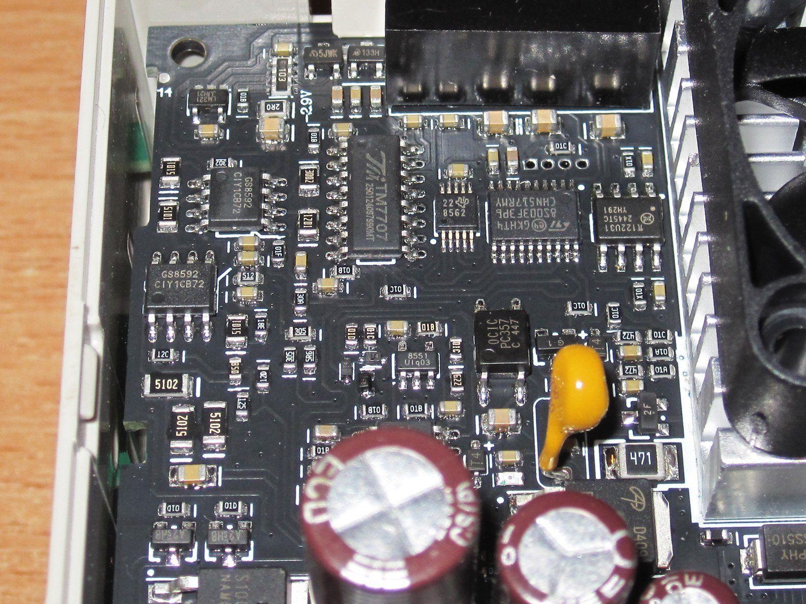
And of course, I had to take it apart.
It comes apart just like the other models: desolder the three output terminals, release the clips, and remove the board.
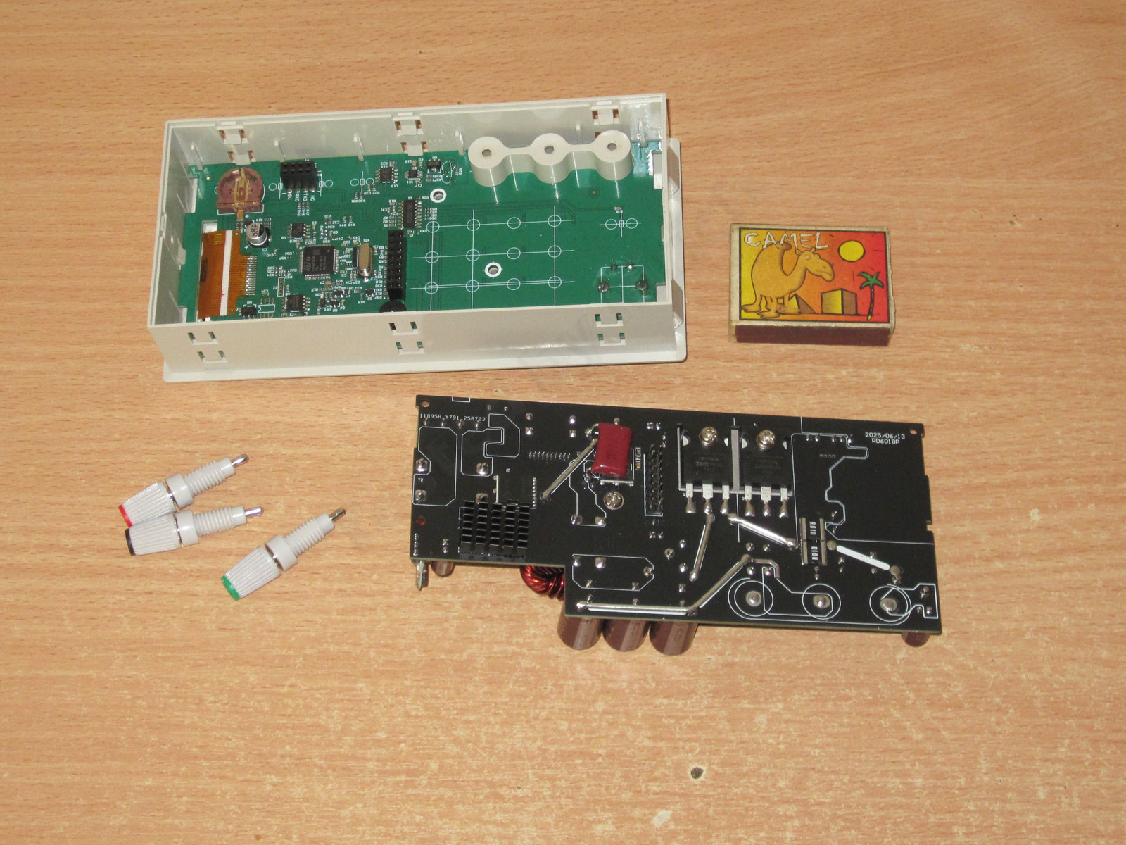
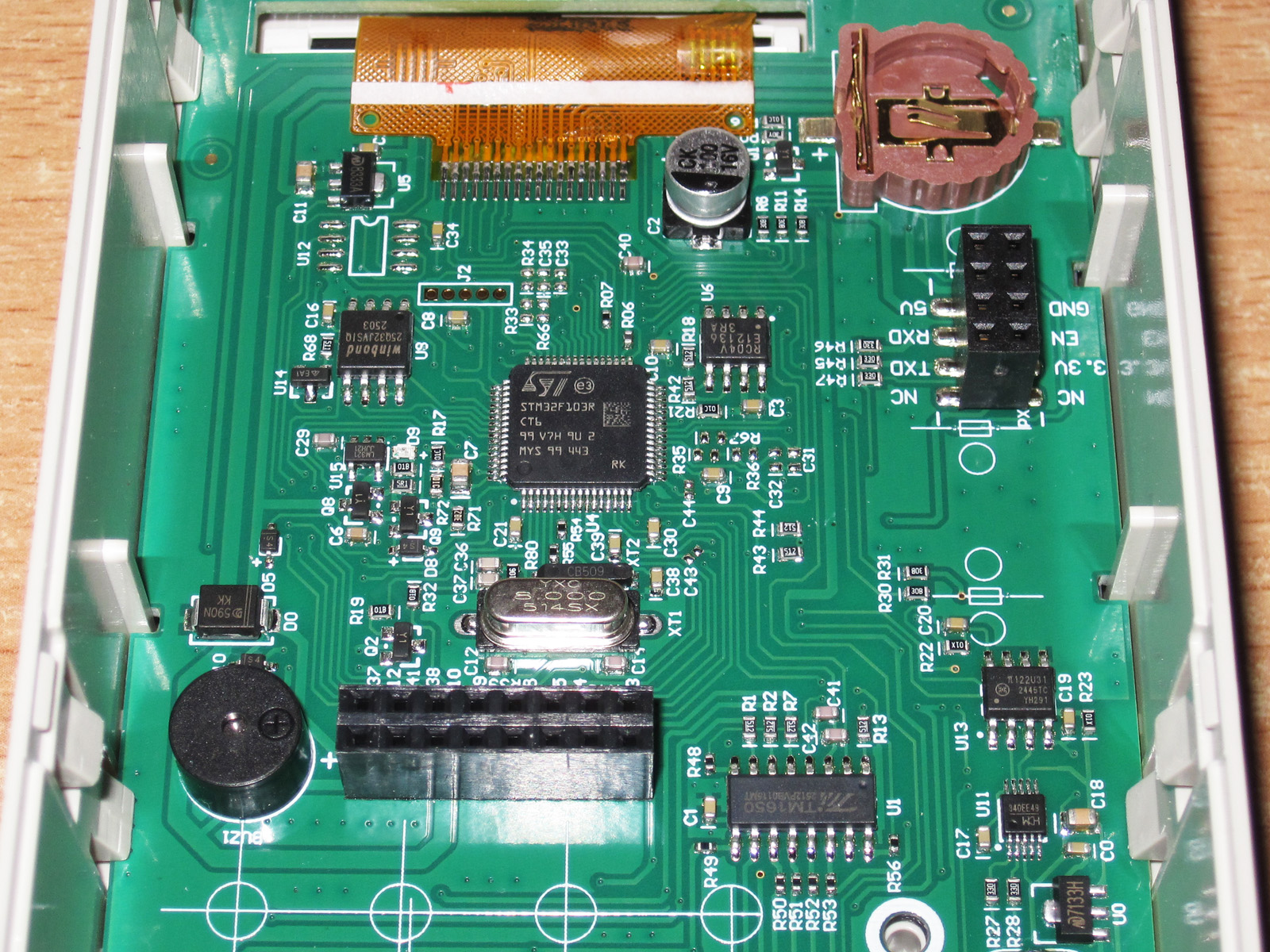
I don’t see any obvious differences on the front-panel board. By the way, I don’t know why they don’t switch all the models to Type-C, but oh well—the manufacturer has its own priorities and decisions.
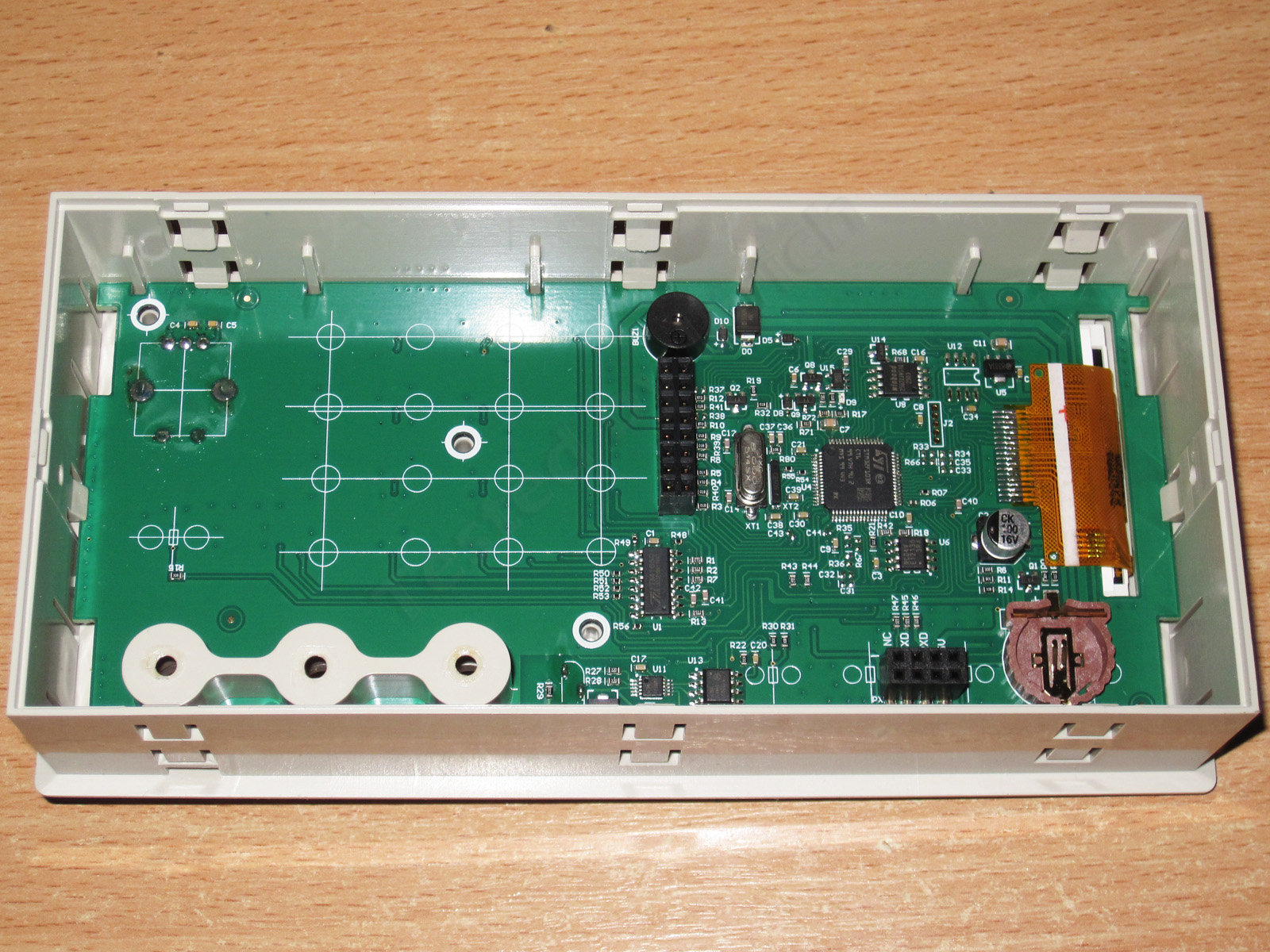
During the inspection, I noticed that something was different after all. It turned out that the microcontroller is the same, an STM32F103, but where there used to be an ARM marking in the left corner, there’s now an ST logo.
The power board was much more interesting to me, of course. I’ll point out right away that many of the high-current traces are reinforced with thick wire.
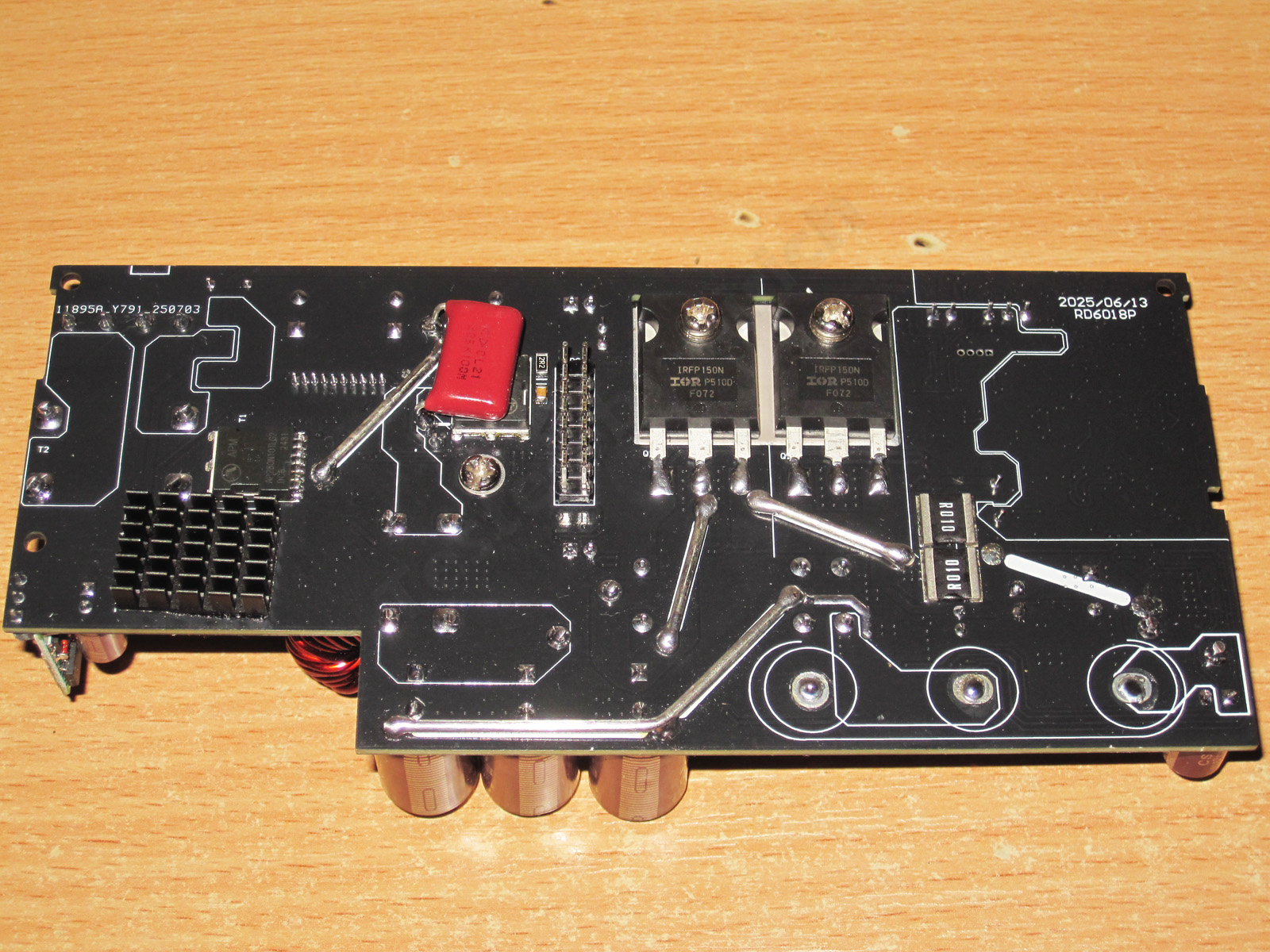
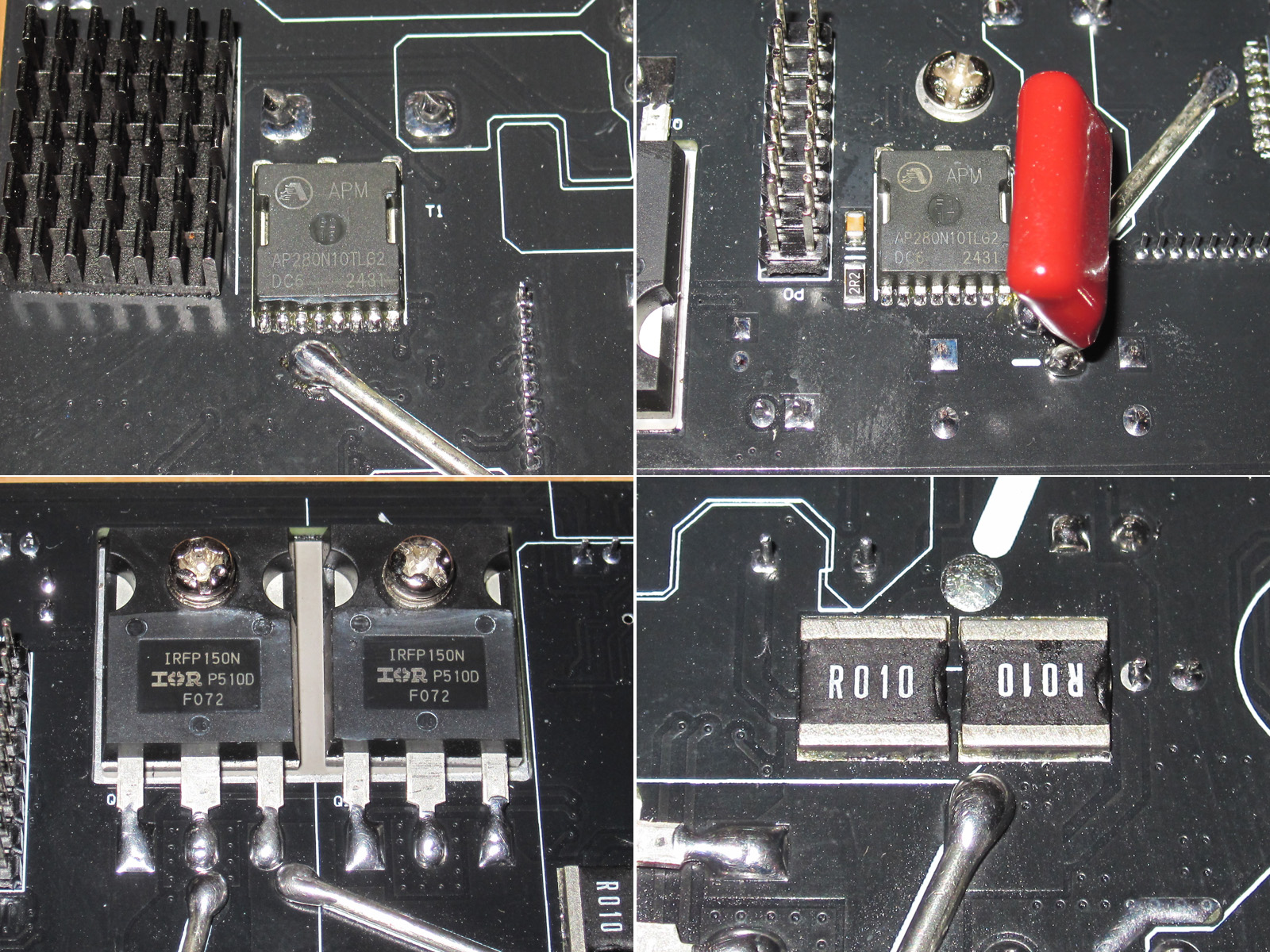
1. Reverse-polarity protection transistor, on the negative supply rail. The auxiliary converter section heatsink is on the left.
2. The second transistor in the DC-DC section.
3. Linear regulator transistors. Interestingly, the 6012P used bipolar transistors, while this one uses MOSFETs. The power terminals are connected in parallel, but the gates don't show continuity between them. It’s interesting to compare the minimum voltage drop: the IRFP150 has an on-resistance of 36 mΩ, while the TIP35 drops about 0.45 V when hot and carrying 10 A. With the IRFP150 at 9 A (half of 18 A, since there are two transistors), the drop will be 0.324 V—not that big a difference, in my opinion.
4. The shunts are large, each about the size of—or slightly larger than—a pair of 2512 resistors, and fairly thick too. One would have been enough in terms of power, but the manufacturer apparently decided to reduce the TCR by splitting the total load between two shunts.
The analog-digital section with the case parts that get in the way removed, in case this comes in handy.
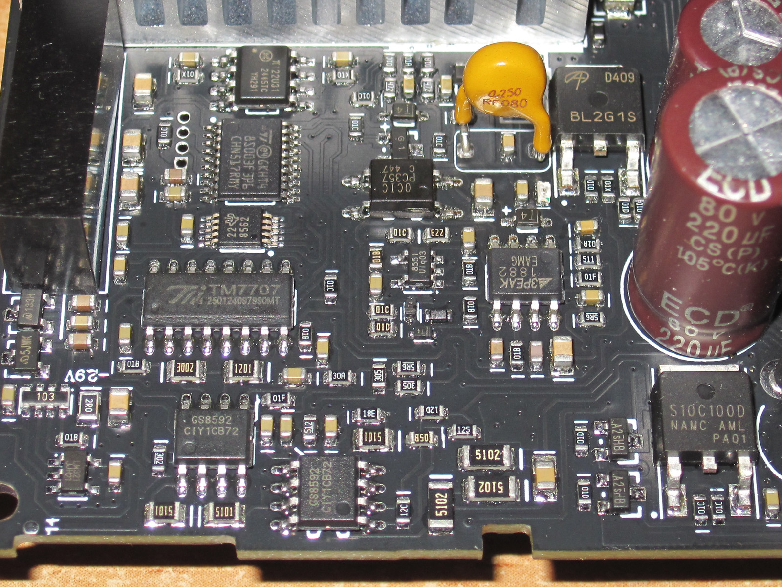
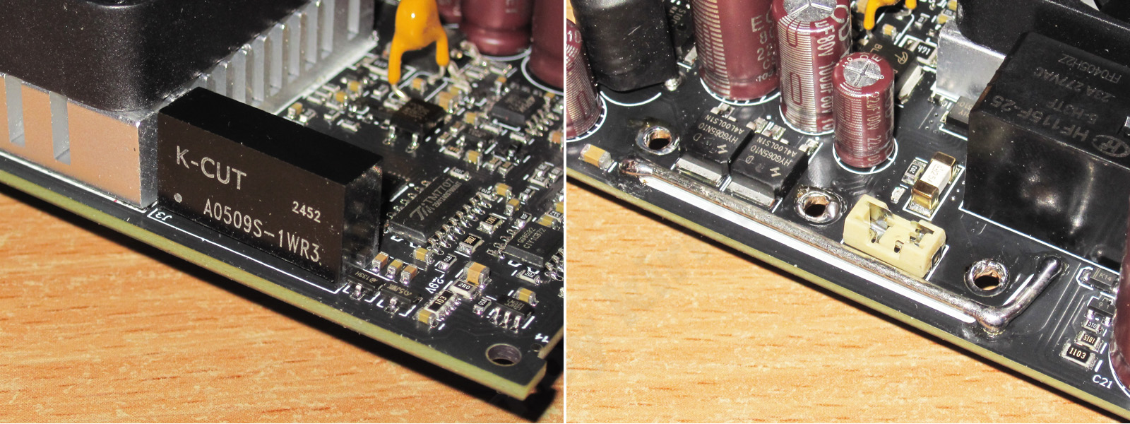
The board also has an isolated DC-DC converter, 5–9 V. In addition, some of the power traces are reinforced on the other side of the board too, particularly the trace leading to the positive terminal in the photo.
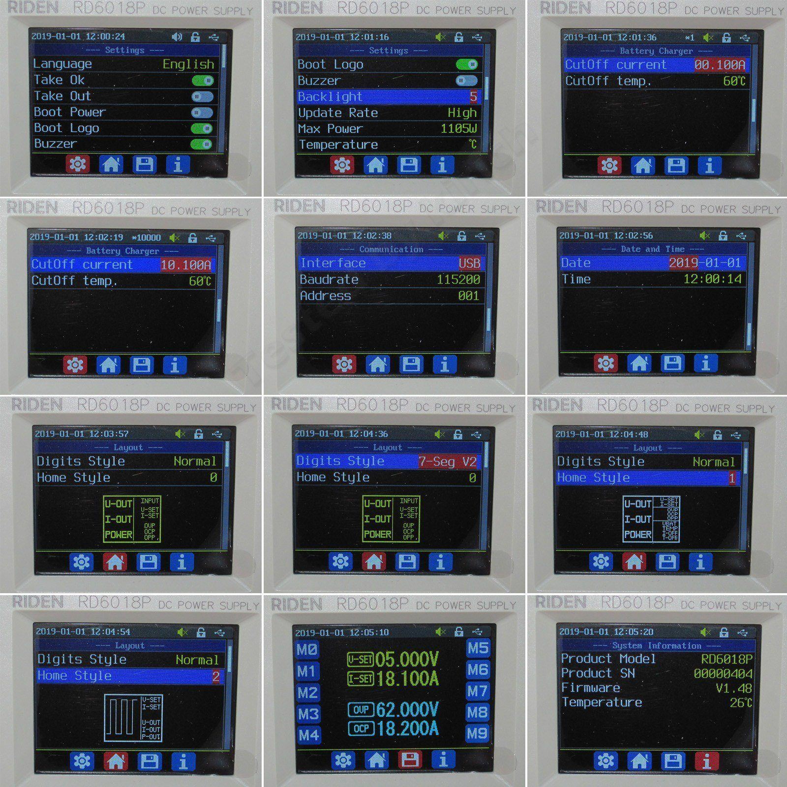
When powered on, it displays a welcome message, then the power supply switches to its normal operating mode with the default screen.
There isn't much new to report here either. I can only note that the current display and setting resolution is 1 mA, and unlike the 6012P, it can't be changed.
As a reminder, the 6006P had one mode, I think 0.1 mA; the 6012P had two modes, 0.1 mA up to 6 A and 1 mA above that. As far as I can tell, this one only has 1 mA, unless I missed how to switch it.
The control menu is essentially unchanged, so I don't see any point in going over it yet again.
First thing, I turn off the sound and set the brightness from 4 to 5. RuiDeng displays are great—bright and sharp.
It's handy that you can not only adjust the charge cutoff current, but also choose the adjustment step size. The slightly unusual part is that the multiplier is shown at the top and selected with the left/right buttons: 1, 10, 100, 1000, 10000.
Here you can also choose the font and display style (you can change these on the fly while it's running), as well as presets.
And now for the tests, which I think are more interesting and useful than a description of the menu.
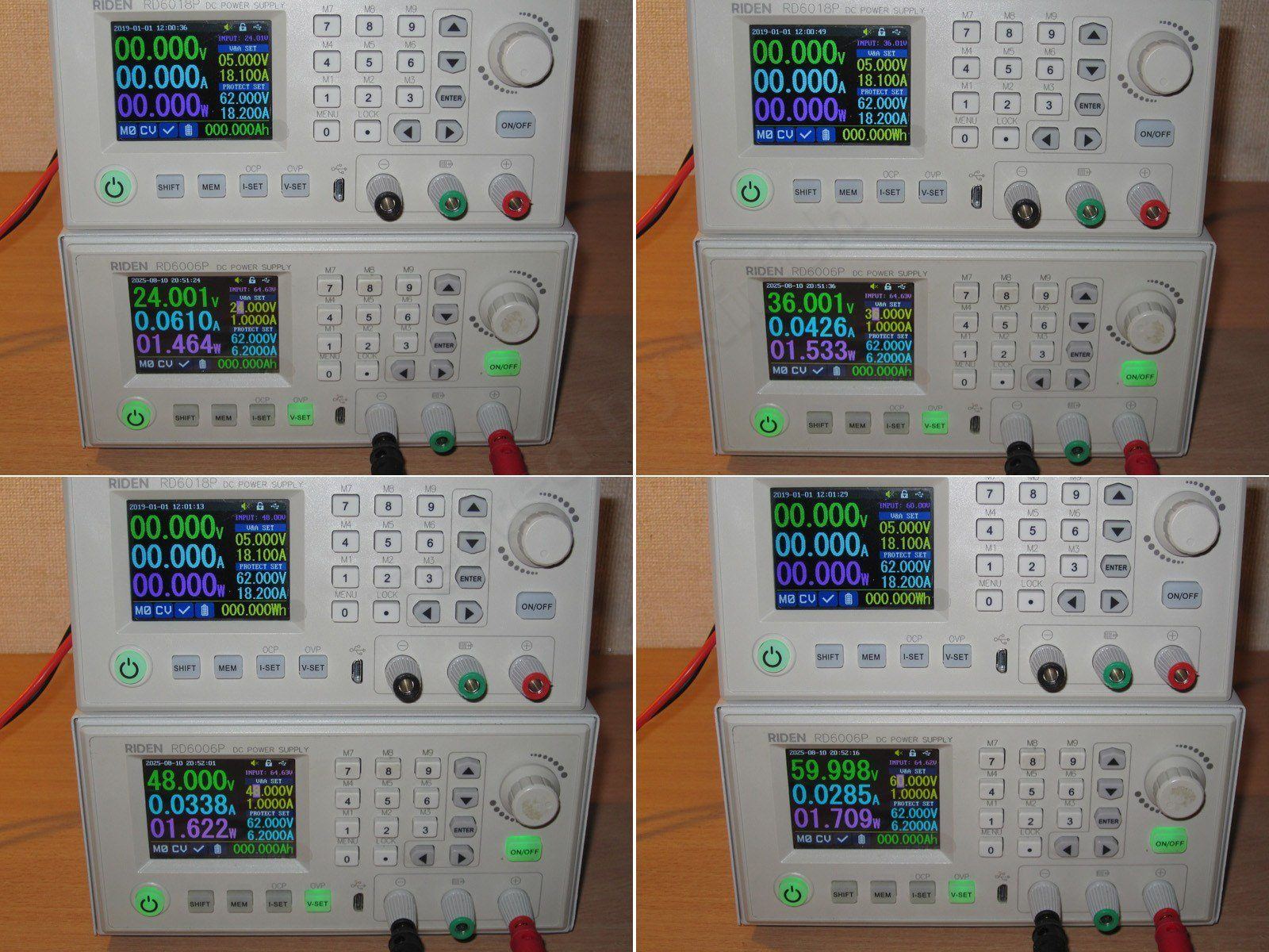
As usual, I'll start with the zero test: idle power consumption at different input voltages, specifically 24, 36, 48, and 60 V. The current (and power) depends on the input voltage, with a range of 1.5–1.7 W; the higher the voltage, the higher the power.
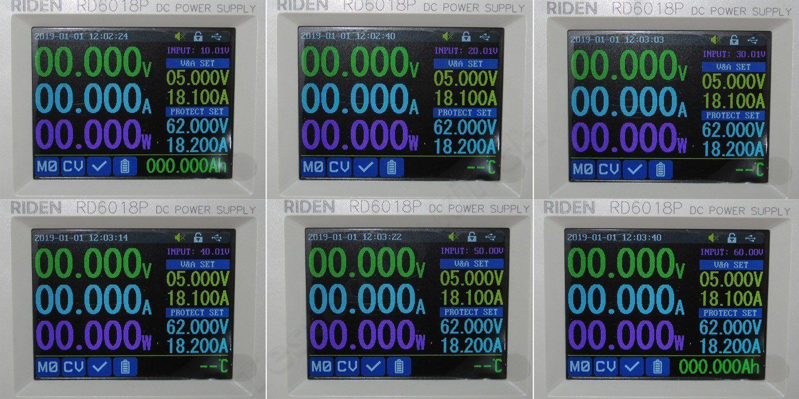
Test one: input voltage measurement accuracy.
It's practically spot-on in some places and reads 0.01 V high in others, but I have no complaints here—the accuracy is excellent.
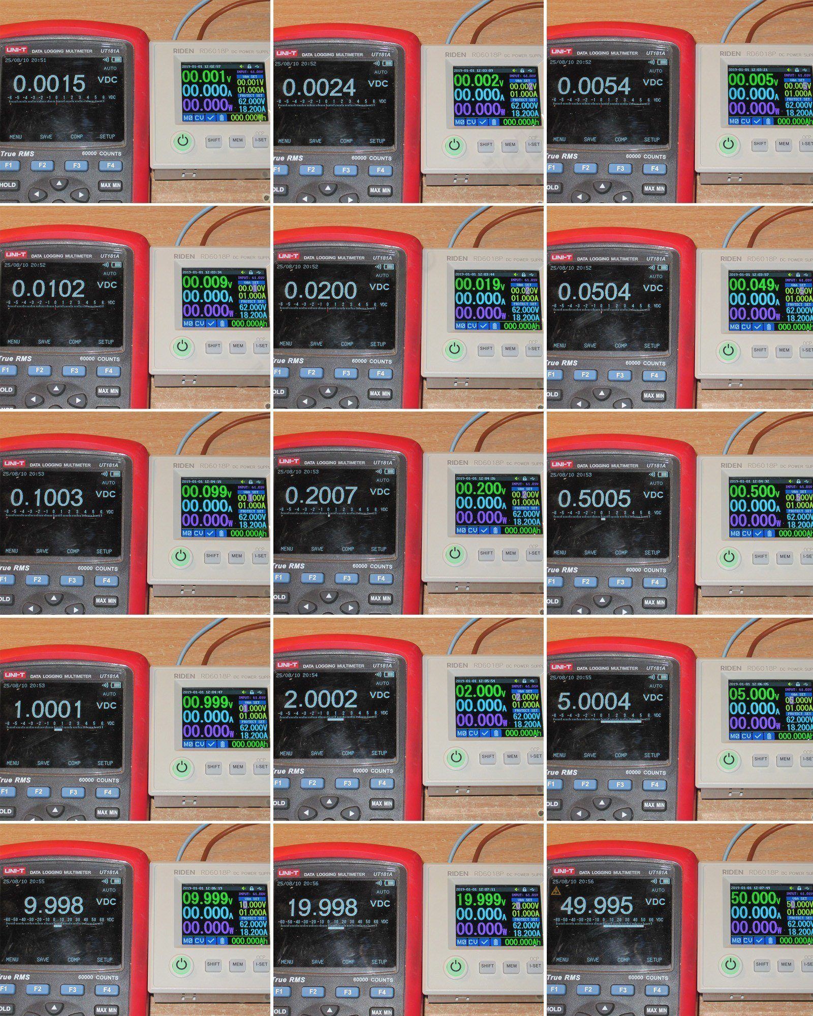
Test two: output voltage setting accuracy with no load. I checked from 1 mV to 50 V using a 1-2-5 sequence.
It's worst in the 1–10 mA range; beyond that, I'd rate it excellent, since the accuracy is more than adequate.
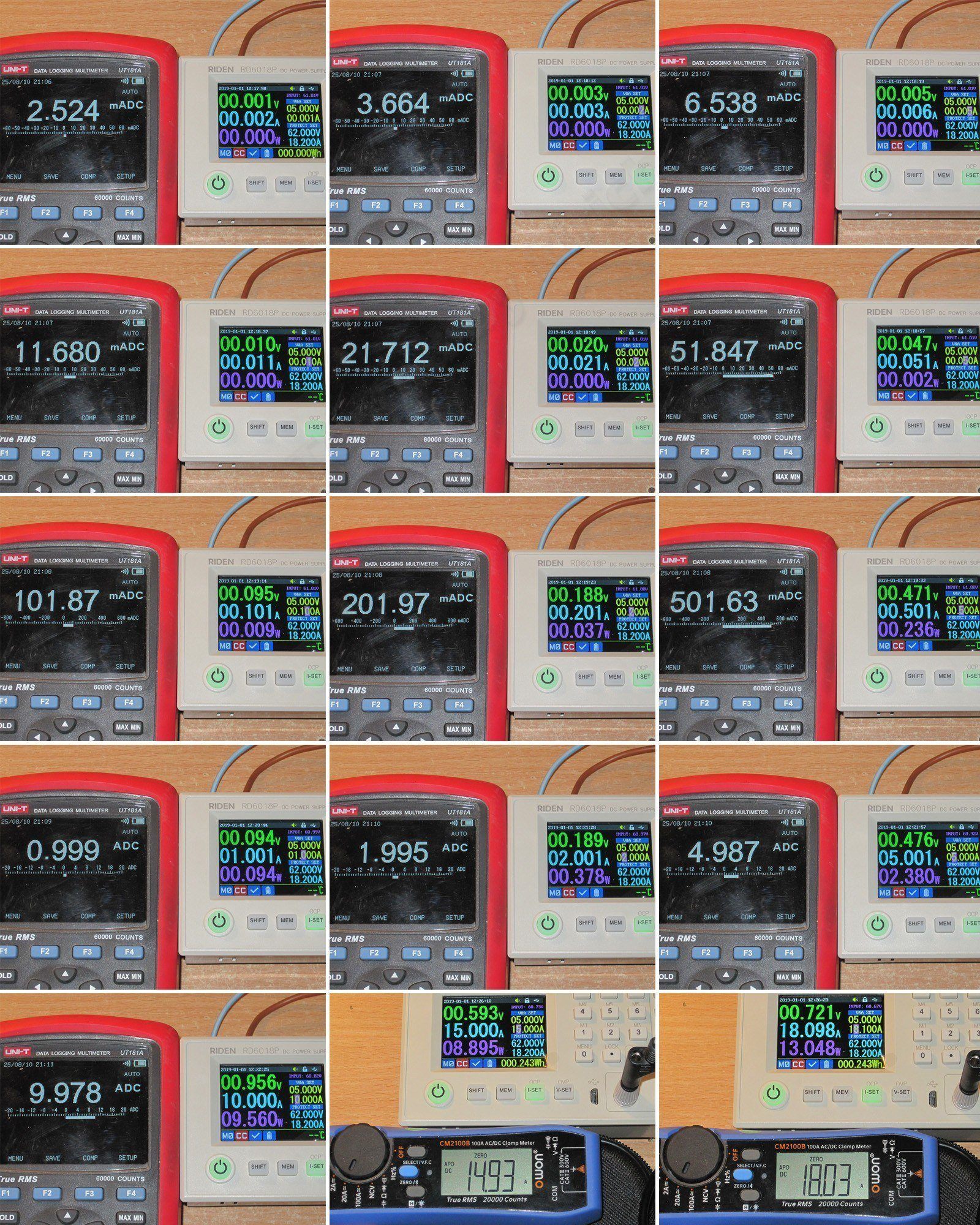
Test three: the same thing for current, from 1 mA to 18 A.
The results are a little worse here. There's a noticeable positive deviation up to about 100 mA; above 1 A, the error changes sign and the current starts reading low, though I don't see anything critical up to 10 A. Unfortunately, I can only measure currents above 10 A with a clamp meter, so the error there is uncertain.
Note that below 1 A, the built-in ammeter also reads slightly high. For example, if we set 100 mA, the multimeter reads 101 mA, and the built-in ammeter also reads 101 mA. On the other hand, all the way up to 5 A, the built-in meter consistently reads 1 mA higher than the set value.
So it probably won't work as a reference standard, but subjectively, the accuracy is perfectly fine for everyday work.
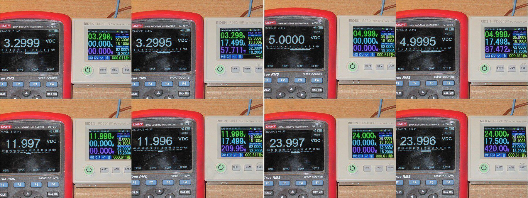
Test four: output voltage versus load. I first set a voltage—3.3, 5, 12, and 24 V—measured it with no load, then measured it again at nearly full current, 17.5 A. The thing is, at 18 A the load caused the converter to switch periodically into CC mode, so I reduced the current to 17.5 A.
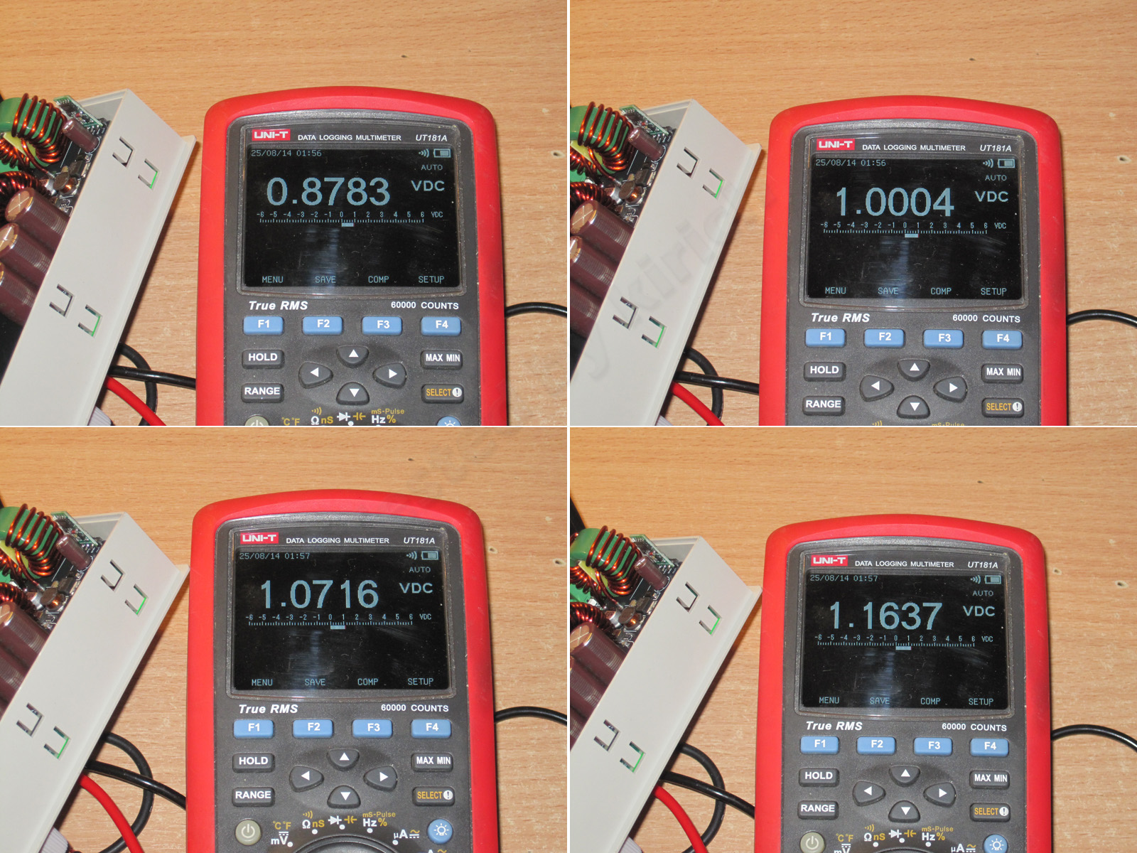
I'd say this is practically perfect: a difference of 0.0–1 mV across the entire current range is great. But keep in mind that this is a two-wire connection, so unfortunately you won't get this accuracy in practice—the voltage drop across the wires will be much greater :(
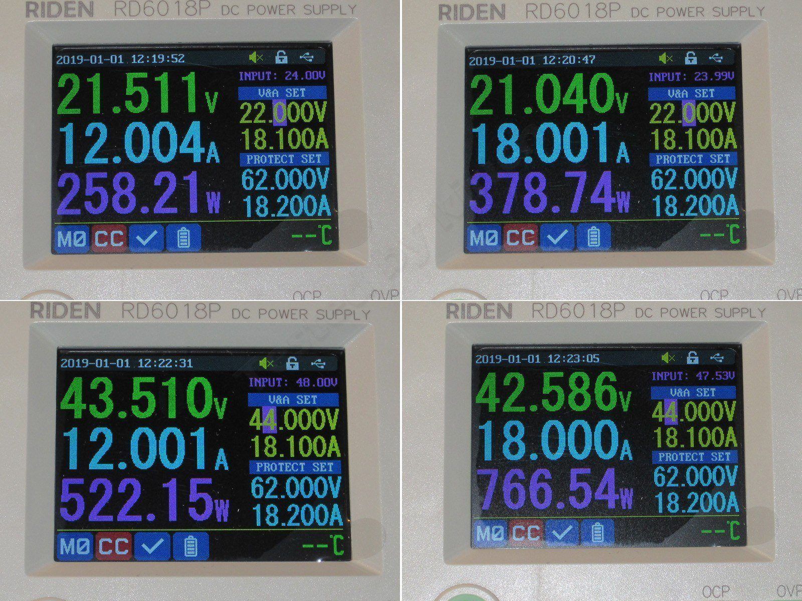
Test five: minimum input-output voltage difference.
I tested at input voltages of 24 V and 48 V. In the first case, the load current was 12 and 18 A. But first, a few words about how the converter behaves in this mode.
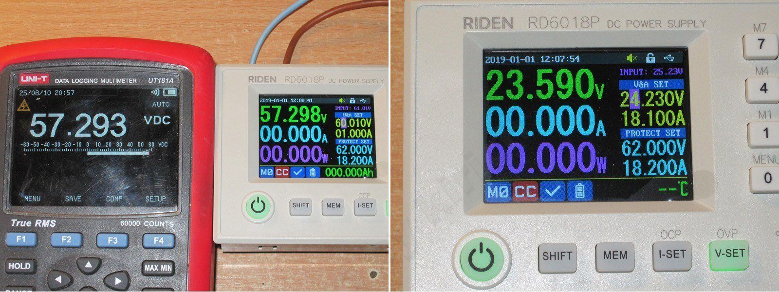
With no load, first of all, there is a minimum difference of 2–3.5 V, and the higher the input voltage, the greater the difference.
Second, the converter won't let you set the output voltage higher than the input voltage. More precisely, the maximum you can set is the input voltage minus 1 V; you can't set it any higher.
And third, the thing that confused me: if the converter can't maintain the set voltage, it displays CC mode, which is a little confusing. I hadn't paid attention to this before—or rather, I hadn't noticed it, because my power supply has plenty of voltage headroom.
And here's the difference at currents of 12 and 18 A.
At an input of 24 V, I got 2.5 and 3 V; at an input of 48 V, I got 4.5 and 5.5 V, respectively. I think the power supply needs to be at least 6–7 V above the target to get the full 61 V—in other words, 67–68 V, and preferably closer to 69–70 V.
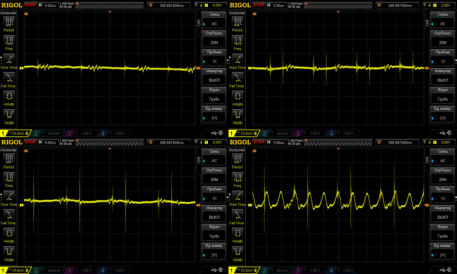
Test six: ripple.
I checked several different operating modes, so there will be a lot of screenshots—sorry about that.
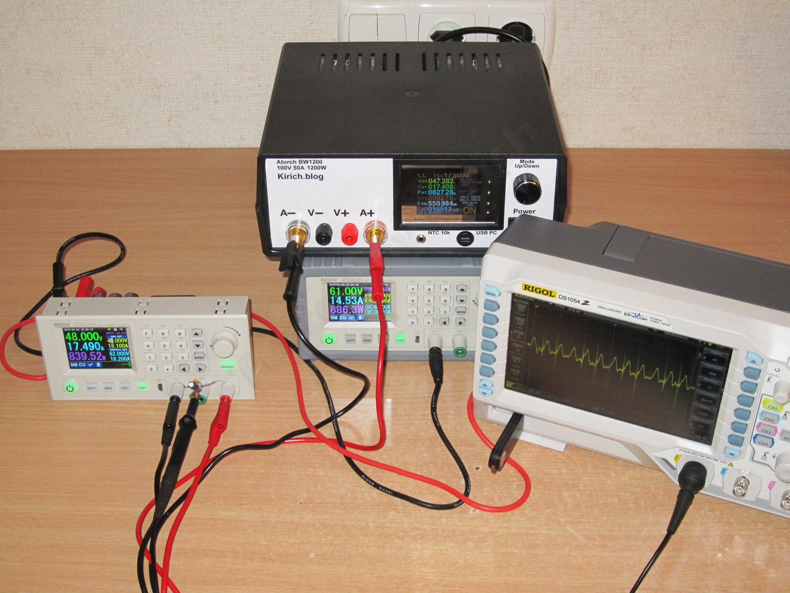
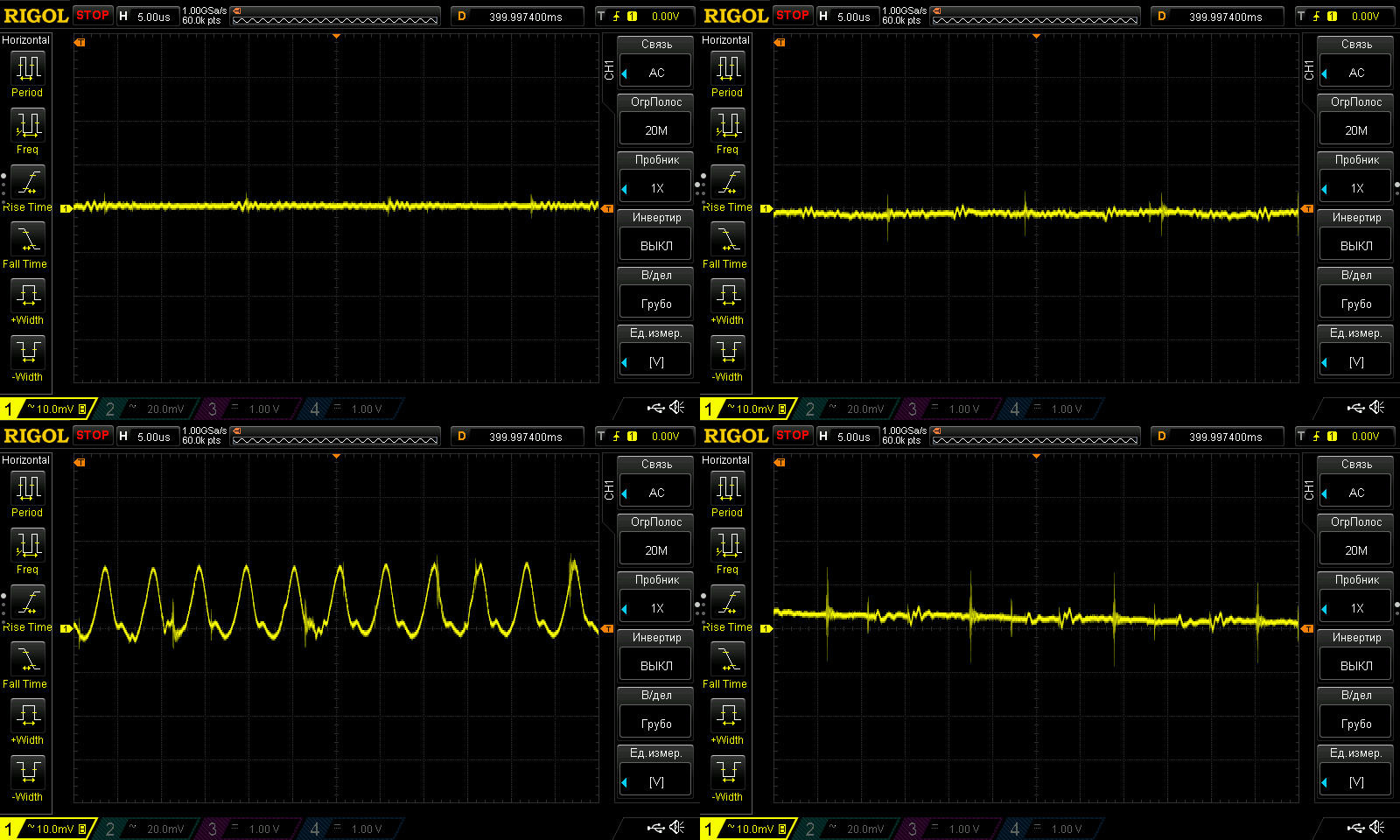
I'll start by measuring ripple at an output voltage of 12 V in these modes: no load, and currents of 6, 12, and 17.5 A.
The specs claim 20 mV, though they don't say under what conditions. Still, that seems about right. The highest ripple was at around 10–14 A.
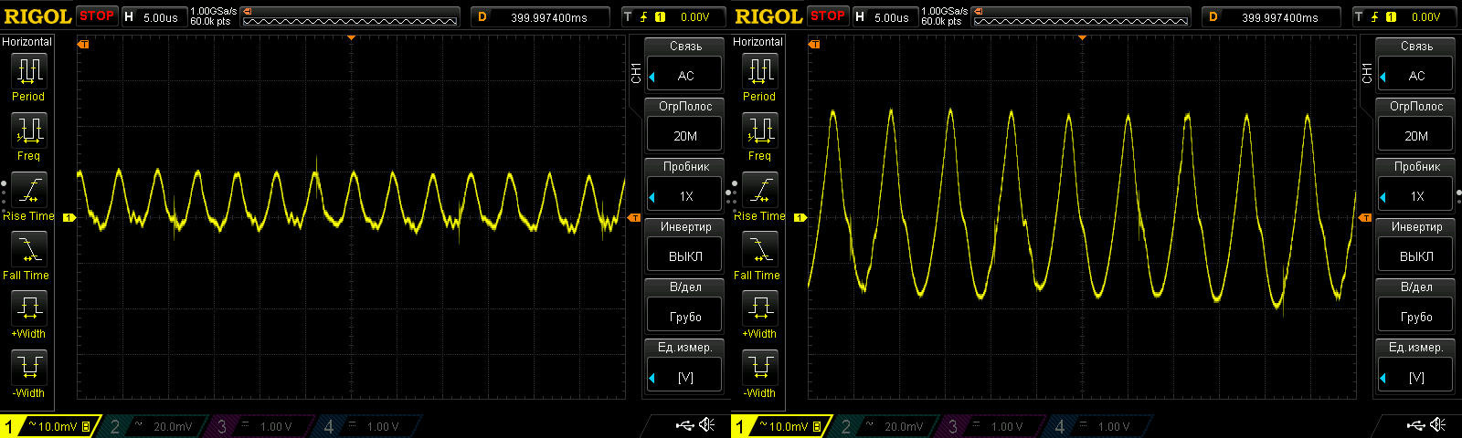
At first, something odd happened. I set the load current to 6 A and took a screenshot, then set it to 12 A and took another. I was surprised, then raised it to 17.5 A and was even more surprised, because there was almost no ripple—unlike the test at 6 A (left), and especially at 12 A (right).
Yes, the ripple at 12 A was unusually high, but what's interesting is that no matter how many times I tried to reproduce those results afterward, it never happened again. A mystery.
These screenshots are all at the same current, 17.5 A, but at different output voltages: 5, 24, 36, and 48 V. Oh, I almost forgot: during the tests, the converter was powered by my RD6030-based power supply.
Overall, not bad. The spikes at 48 V were a little concerning, but on the other hand, we're dealing with a 1 kW power supply and 10–20 mV of ripple, which is very difficult to achieve.
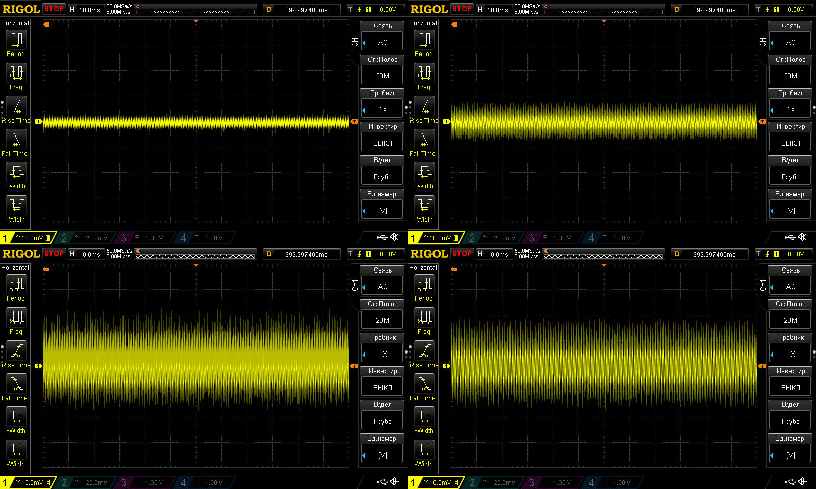
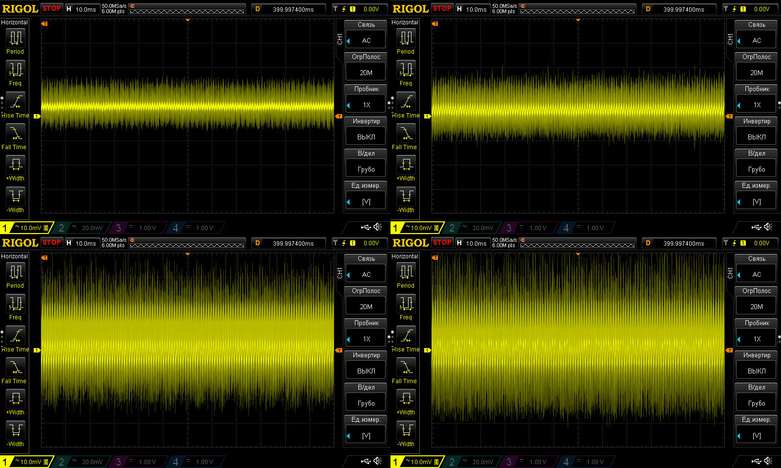
I hadn't run this test before. Here I decided to look at low-frequency ripple. I think the RD6030—and more specifically, its power supply—is adding a lot of noise, but we can still get a general idea of what's going on.
The test conditions are a little different. I didn't see the point in testing with no load, so I tested at 3, 6, 12, and 18 A, with an output voltage of 12 V. Again, the waveform is most "filled in" at 12 A.
The same load currents, but at 48 V. It's hard to say—there's definitely noise, but most of it comes from the spikes, and those are easy to suppress even with just wires. Still, you can see that ripple is also higher at 12 A, at least to my eye.
Test seven: transient response
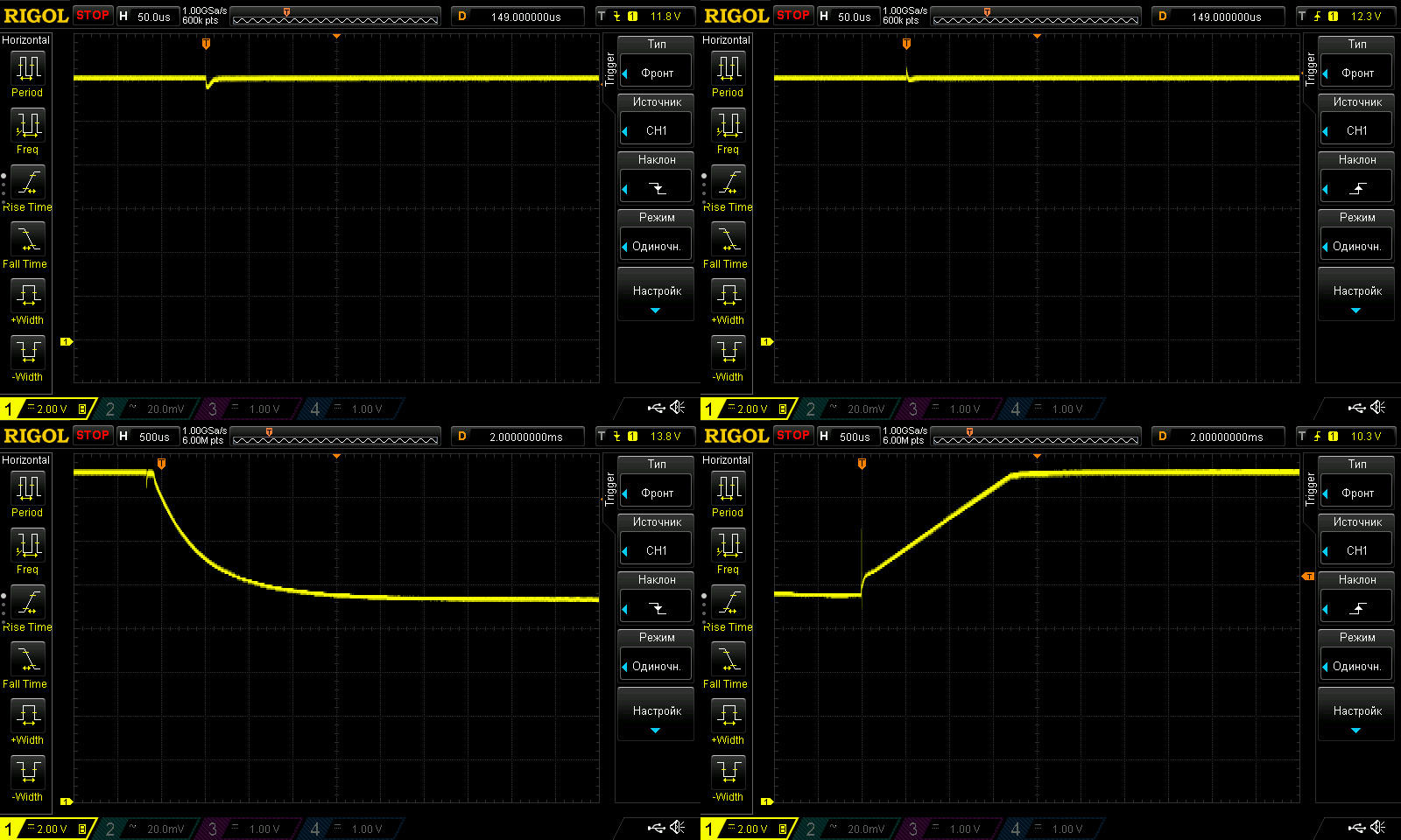
First, applying and removing 5 V at the output with no load. I had to modify the test procedure a little:
1, 2. Applying 5 V, with the current set to 1 A on the left and 18 A on the right. You can see a step in the right-hand screenshot. It occasionally appeared with the current set to 1 A as well, but very rarely; set it to 18 A and it's always there.
3, 4. Removing the output voltage. No steps appeared here, but if you look closely, the shutdown in the second screenshot takes about twice as long. This confirms two things: the capacitors are connected in parallel with the output, and they are switched in according to the set current, not the output voltage. In other words, if you set it to 3 A, the capacitance is at a minimum; set it to 18 A, and it's at a maximum.
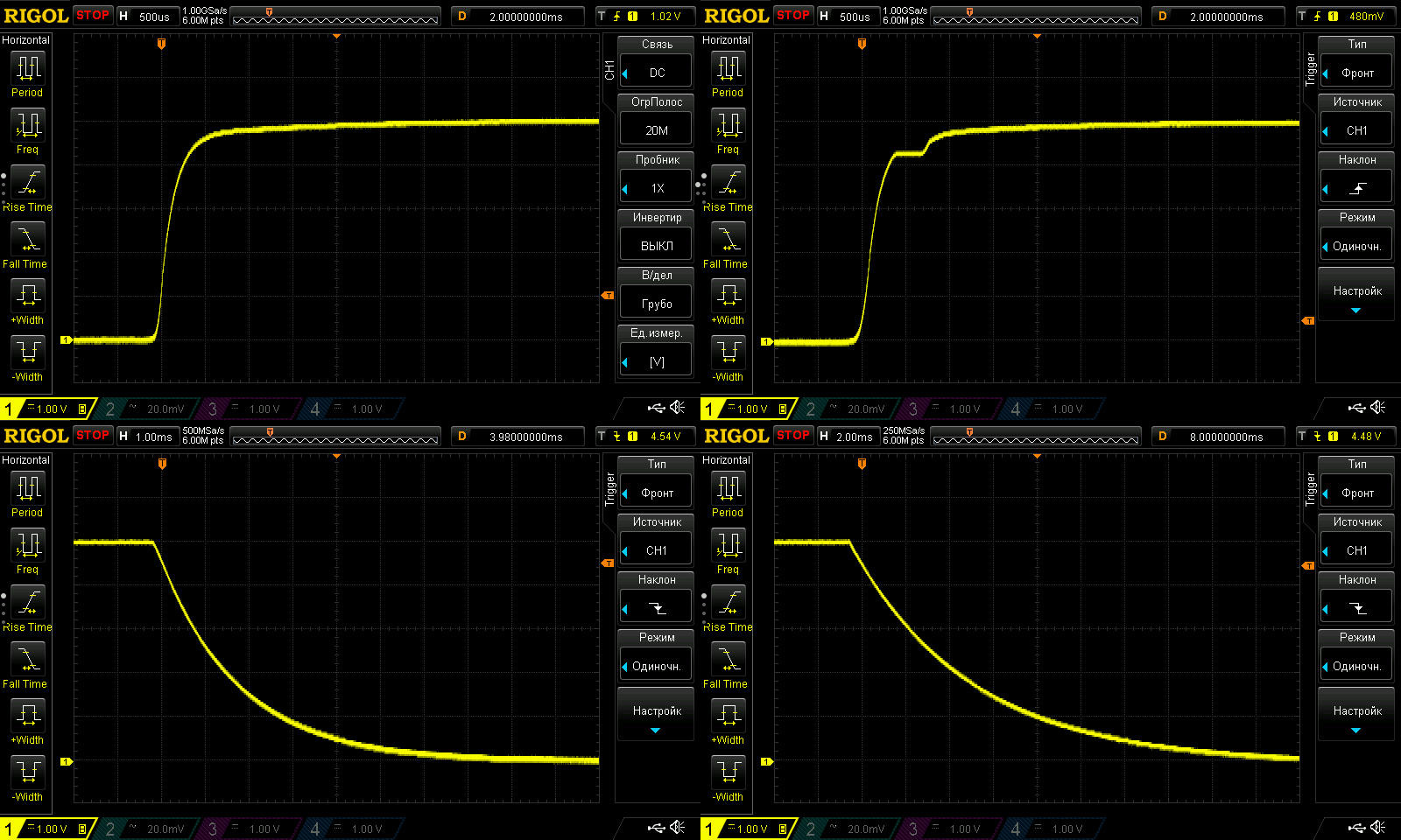
1, 2. Connecting and disconnecting an additional load. The power supply output is 12 V, with a 30 Ω resistor permanently connected. A 3.3 Ω resistor is connected in parallel with it, so this shows the response to a current step from 0.4 to 4 A and back from 4 to 0.4 A. Overall, no complaints.
3. Transition from CV mode to CC mode: voltage 15 V, load current 4.5 A, current limit set to 3 A.
4. Same thing, but the reverse transition, from CC to CV/
Looks fine to me.
The “soldering iron” test is essentially connecting and disconnecting an active load—or, more precisely, a T12 tip at 12 V—and I have no complaints at all here.
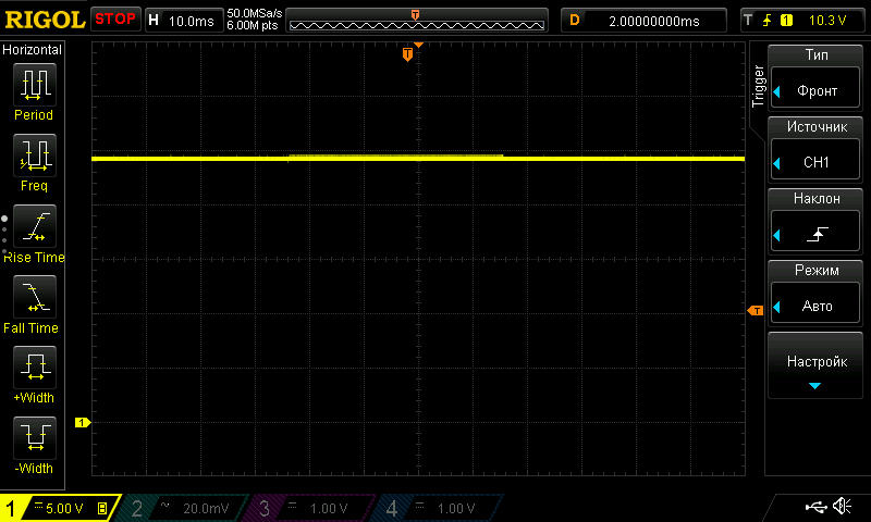
Test eight: evaluating the converter’s efficiency.
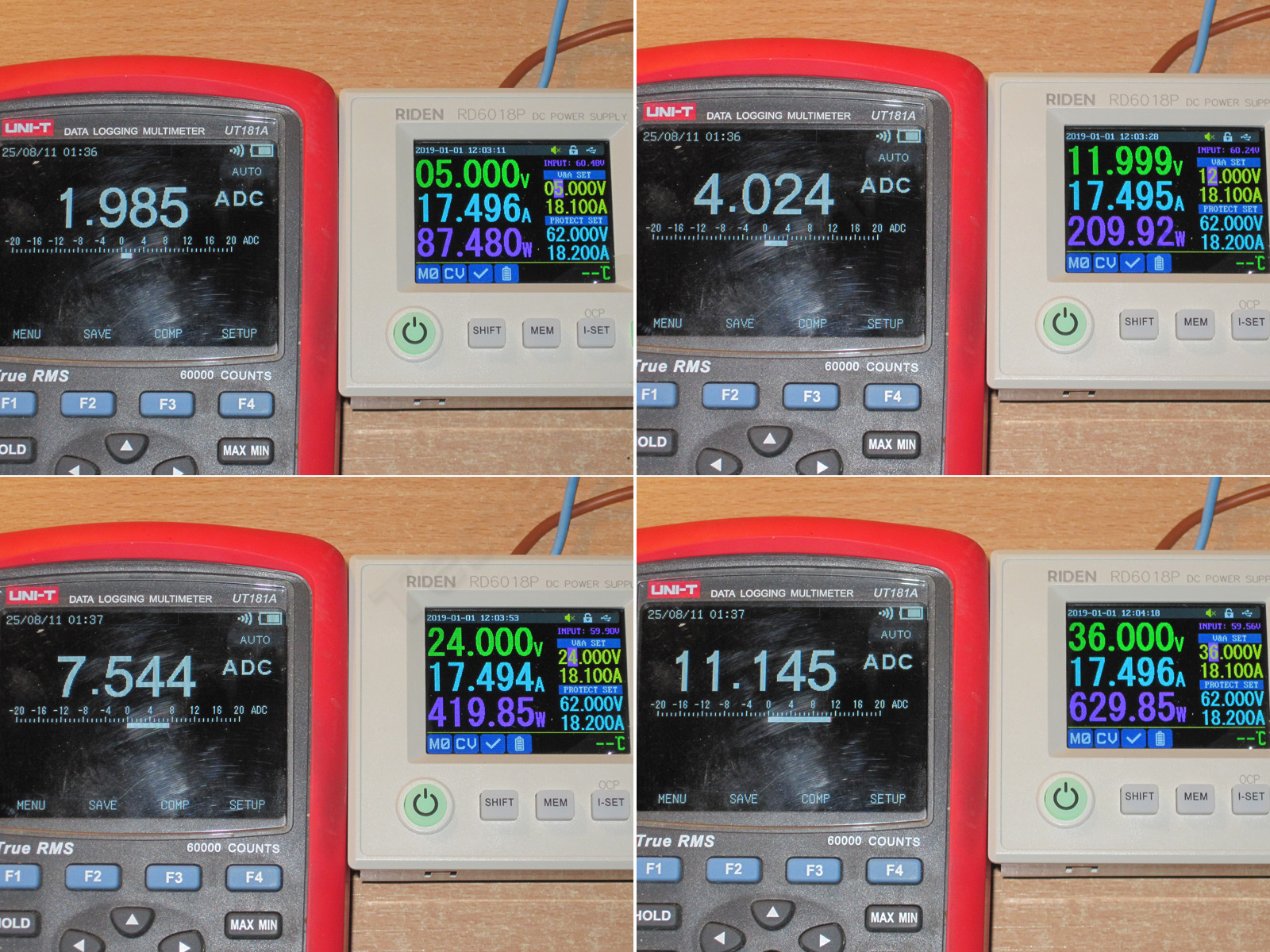
I tested it with an input voltage of about 60–61 V and a current of 17.5 A, with output voltages of 5, 12, 24, and 36 V.
The results:
Output voltage — efficiency — power loss (efficiency and losses for the 6012P and 6006P)
5 V — 72.9% — 38.6 W (63.5% — 34.9 W, 60.0% — 20.1 W)
12 V — 86.6% — 32.5 W (79.6% — 36.7 W, 78.3% — 20.0 W)
24 V — 92.9% — 32.0 W (87.9% — 39.35 W, 87.7% — 20.27 W)
36 V — 94.9% — 33.9 W (91.7% — 38.68 W, 91.6% — 19.84 W)
48 V — not tested (94.1% — 36.1 W, 93.8% — 18.9 W)
60 V — not tested (95.5% — 34.06 W, 94.6% — 19.1 W)
For comparison, here are the results for the standard 6018 and 6012 versions. Their losses are noticeably about 1.5–2 times higher.
5 V — 83.3% — 18.07 W (80.6% — 14.47 W)
12 V — 92.0% — 18.6 W (90.7% — 14.7 W)
24 V — 95.8% — 19.13 W (94.8% — 15.57 W)
36 V — 97.2% — 18.12 W (96.8% — 14.36 W)
I didn’t test 48 or 60 V, but the overall picture is already clear—and interesting. Efficiency is higher in every mode tested, and losses are even lower than on the 6012P, though higher than on the 6006P. To be honest, I expected the losses to be higher than on the 6012P.
All in all, that’s nice.
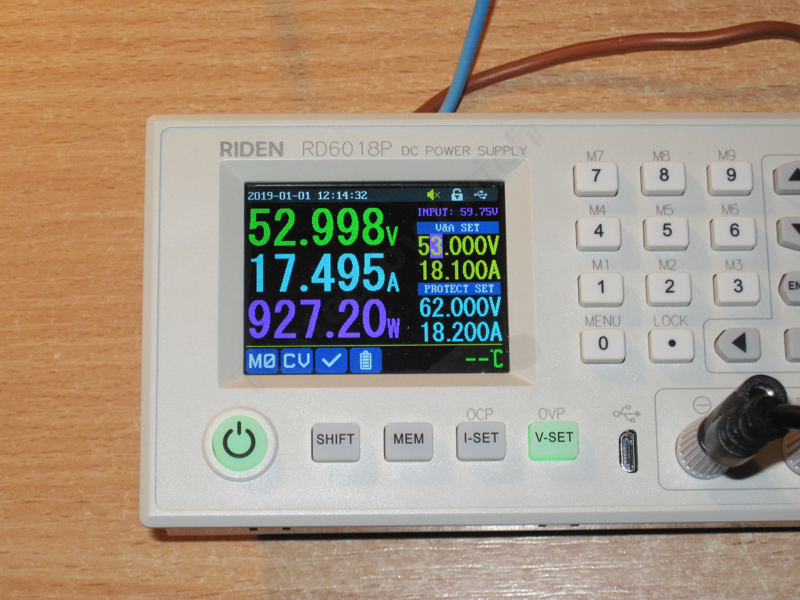
Test ten: evaluating temperature rise.
I applied 61 V to the input (with some voltage drop across the wires), set the output to the highest voltage the converter could still regulate, and loaded it at 17.5 A. The output power came to 927 W. The maximum rated power is 60 × 18 = 1080 W; the maximum actual power is 61 × 18.1 = 1104 W. In any case, I wasn’t far off. I could have installed this converter in place of my 6030—the power supply there is rated for 1500 W—and run it at full power, but that would have been rather inconvenient, and the results probably wouldn’t have differed much.
Thermal images taken about 5 minutes after the test began (top) and another 10 minutes later (bottom).
Two components stand out as running particularly hot: the transistor mounted on the large heatsink and the input fuse. The first reached about 90–95 °C, the second about 108 °C.

Test eleven, an additional one: measuring the voltage drop across the linear regulator.
I tested four operating conditions: output voltages of 5 and 40 V, and load currents of 1 and 17 A.
At low current, the drop is stable; at high current, it gradually increases. I recorded the voltage once the rate of increase had noticeably slowed.
1, 2. 5 V at 1 and 17 A
3, 4. 40 V at 1 and 17 A.
I should mention that the regulator’s losses are fairly substantial—about 20 W at maximum current. On the other hand, the lower its losses, the less headroom there is for adjustment.
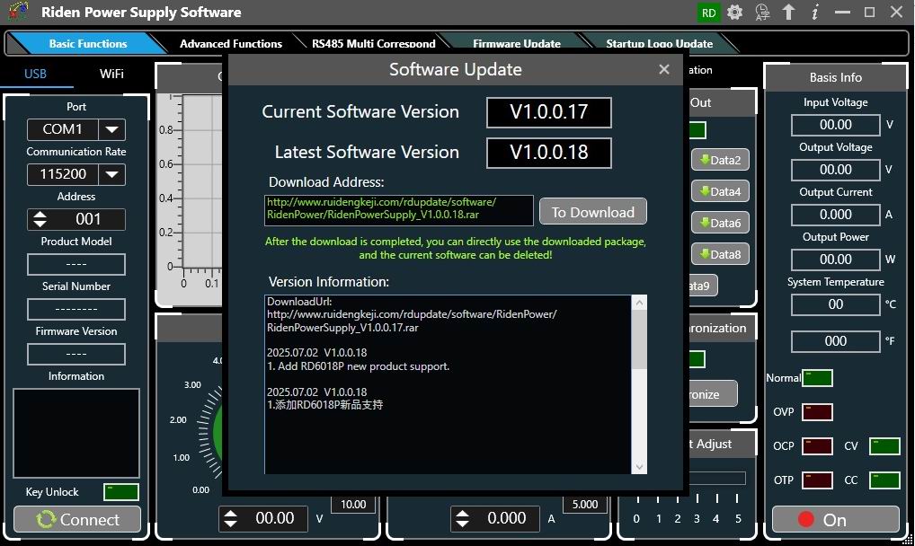
To download the software, I went to the product page, but both links there led to the smartphone app, so I went to the MAX version page, where the link was correct.
On first launch, the software notified me that a newer version was available. For some reason it wouldn’t download, so I downloaded it later. I wanted to replace the screenshots, but couldn’t see any difference at all.
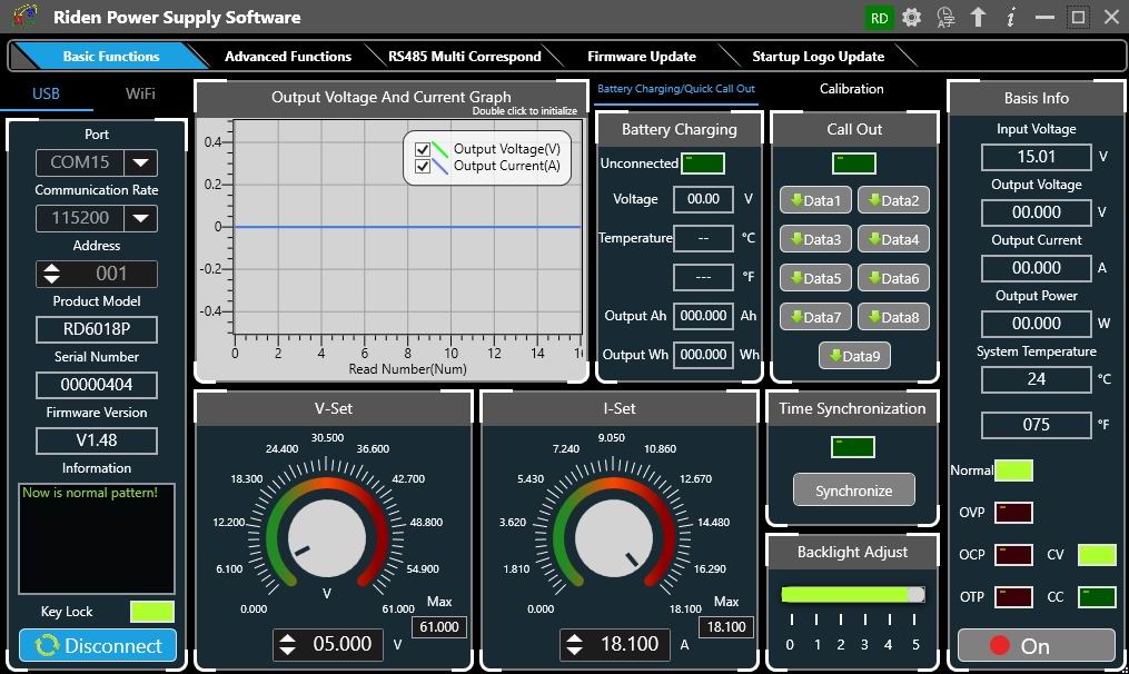
There are essentially two important screens here: the main one, where you control and monitor all the functions. By the way, the 6012P had a 6/12 A selector on the bottom; there’s no such option here, which once again shows that the converter always operates in a single mode.
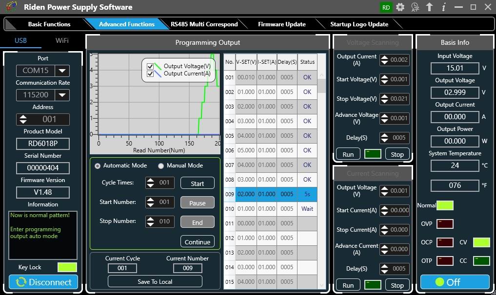
And the additional menu for controlling programmable operating scenarios seems unchanged as well.
Conclusions.
There’s not much new to say here. Yes, ripple is a little higher than on the RD6012P, but the power is also one and a half times greater.
In my opinion, having just one operating range is more helpful than limiting, although on the other hand, some people may find it restrictive.
I’m pleased that the manufacturer managed to increase the current and power by a factor of 1.5 while also achieving higher efficiency than the previous hybrid version. That means the engineers aren’t just focused on increasing power, but are also improving the circuit design and components.
Voltage-setting accuracy is excellent, as is voltage regulation under varying loads. Current-setting accuracy is very good; it’s hard for me to judge the 10–18 A range, since my clamp meter isn’t accurate enough.
Subjectively, this is a very interesting module, although to be fair, I don’t know what tasks specifically require this model rather than the RD6012P.
For example, I have three power supplies: the RD6006P for small, frequent jobs, the RD6030 for heavy-duty work (I’m really looking forward to the 6036), and the RD6012P. I use that one the least; it’s more of a backup in case the others aren’t enough.
What I mean is that the RD6018P is quite good, but does a hybrid unit with this much power really make sense? On the other hand, if you don’t mind paying a bit more than for the standard version, I’d go for the hybrid one rather than the standard model, simply because it has less ripple and responds faster, even though its efficiency is lower and its losses are about 1.5–2 times higher.
That’s probably all for now. I hope this was useful, and as always, I’d be glad to hear your comments.
rd6018p, riden rd6018p купить, источники riden обзор, rd 6018, riden, riden 6018p купить, rd6018 max, riden 6018p, 6018p max, rd6018 jn rd6018p, https://www.kirich.blog/obzory/bloki-pitaniya/1282-gibridnyy-reguliruemyy-preobrazovatel-rd6018p-ot-riden, riden rd6036
Questions and answers
What are the output ratings of the Riden RD6018P?
The article gives an output range of 0–60 V and 0–18 A, with a maximum output power of 1080 W.
How does the RD6018P compare with the RD6012P?
The RD6018P supports one and a half times the current and power. The author notes that its ripple is slightly higher, but says the hybrid design has lower ripple and a faster response than a conventional converter.
What comes with the Riden RD6018P?
The basic package includes the converter, an external temperature sensor, an input power terminal block, two power cable lugs and a 25A fuse.
This model is included in the summary table: Comparison of adjustable converters for a bench power supply
The figures from this review are in the measurement database: Converters
Discounted products
You may be interested in



Discounted products
All the content on the site and the advice are free, but we’d be grateful for your support of the project and the channel!
Comments4
Only registered readers can comment. It takes a minute to sign up, and you can log in with the same account you use on the forum.
Log inRegister
Comments are published in their original language.