
5 V 8 A Voltage Converter with Four USB Outputs
I’ve mentioned before that I order various useful things for a friend and post reviews of them. But since reviews sometimes get delayed for various reasons, I decided it would be more convenient to order one or two of these items for myself to try out, provided they’re of interest to me. That’s what I did this time: the original order was for 10 boards, and I ordered 10+1 for myself.
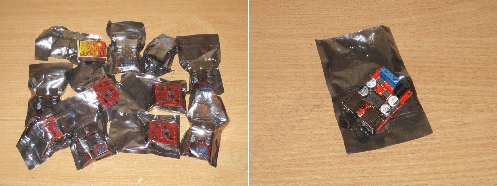
The listing described it as a non-isolated voltage converter with an input voltage of 8–35 V and a 5 V output rated for up to 8 A.
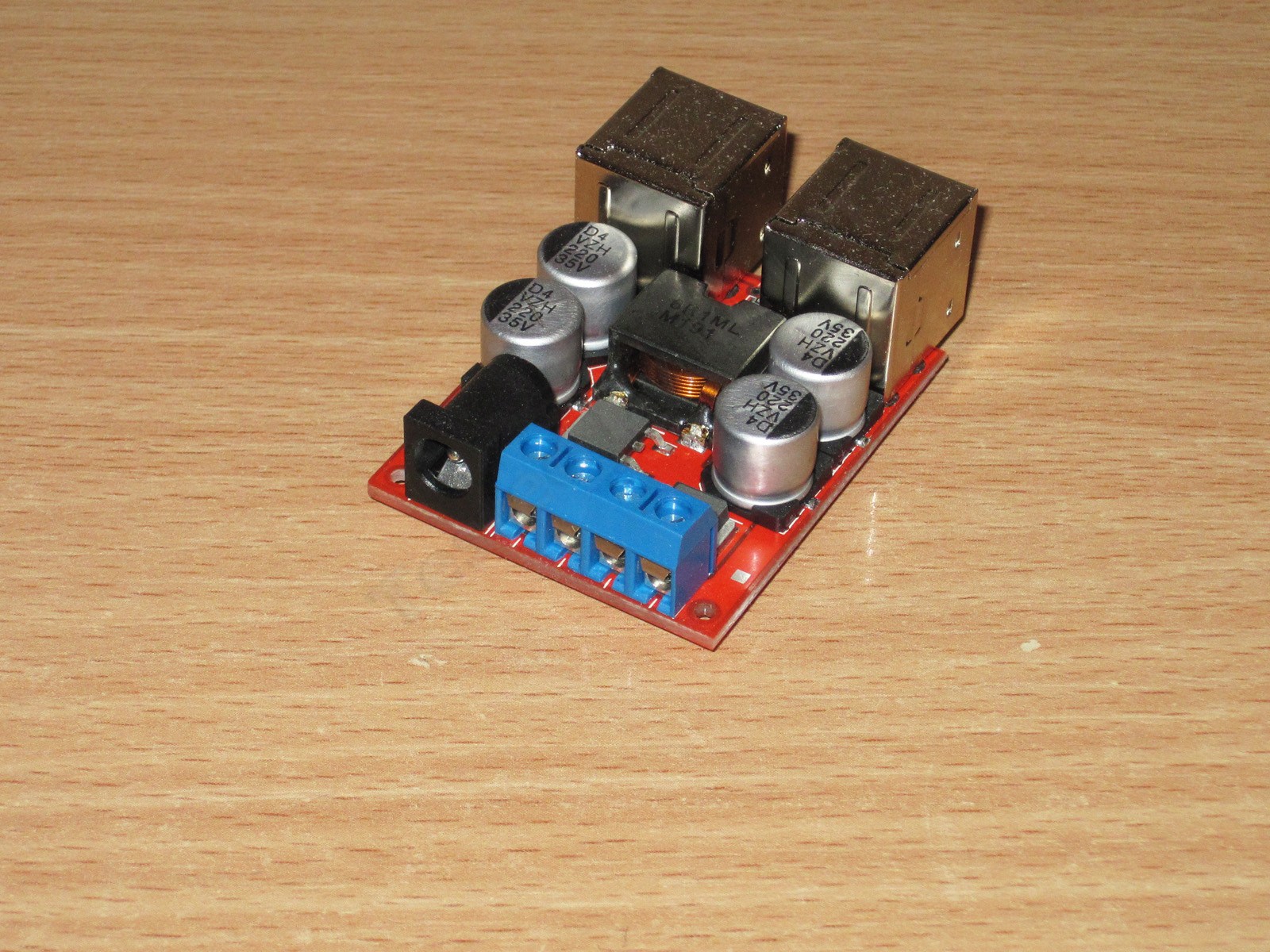
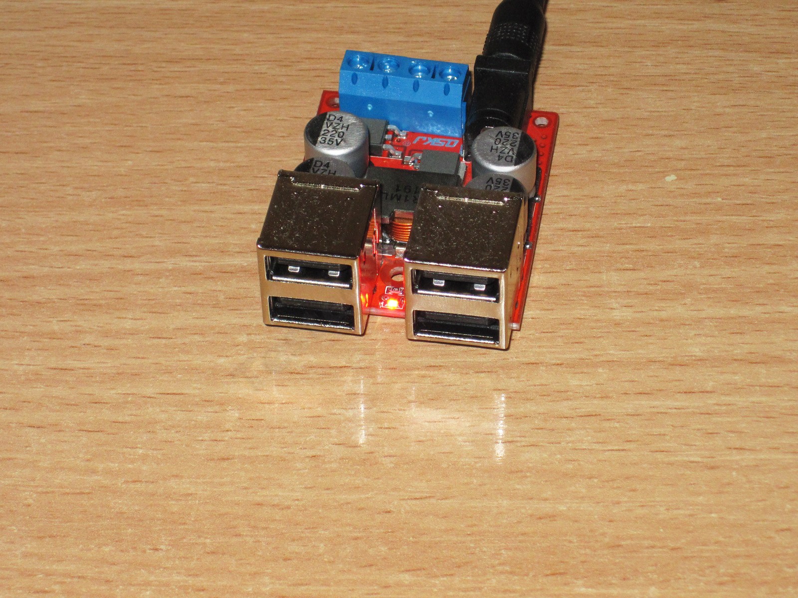
The board is compact—excluding the connectors, it’s about the size of a matchbox.

The input connector and terminal block are on the side opposite the USB ports. The terminal block provides both input and output terminals. In other words, you can use this converter without connecting anything to the USB outputs, which can sometimes be useful.
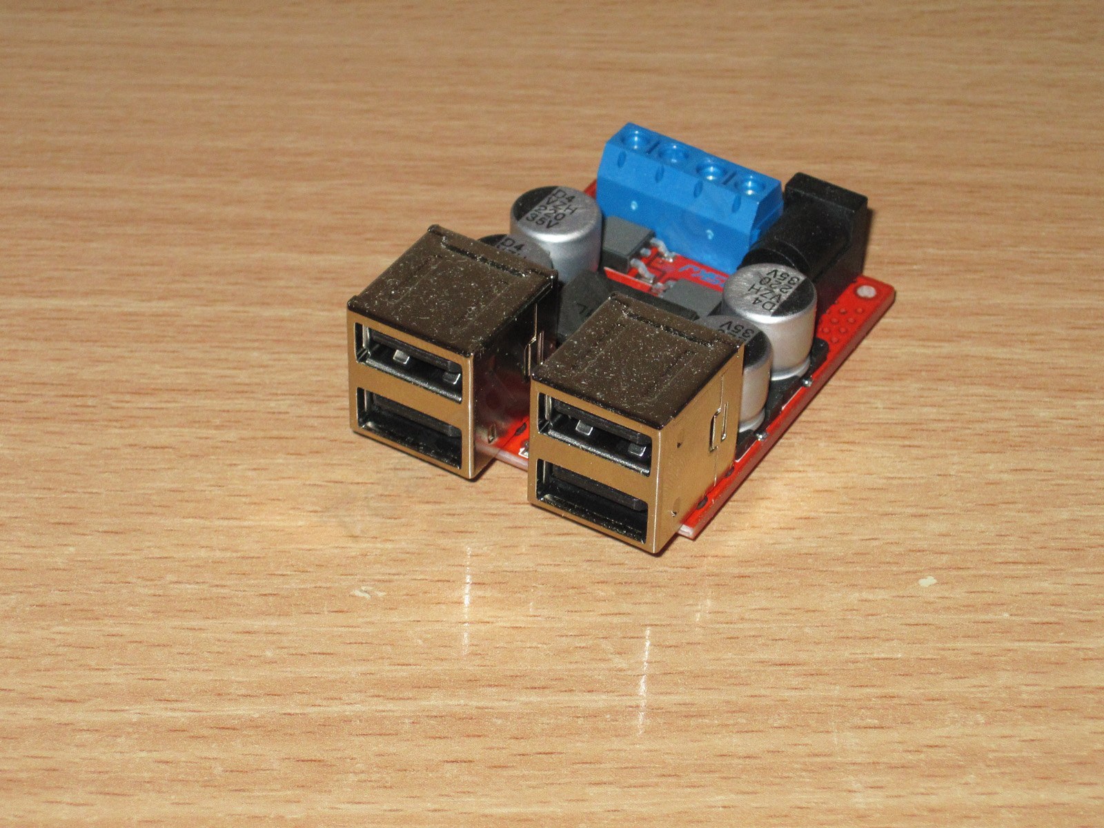
The other side has four USB ports, arranged in two pairs. They were very tight at first, but loosened up after two connections.
On top are a pair of transistors (the converter uses synchronous rectification) with their markings removed, a power inductor, and four 220 µF, 35 V capacitors.
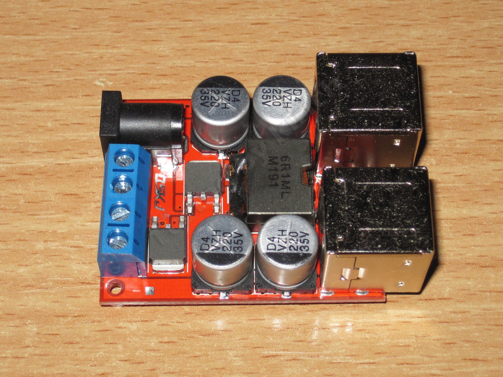
Since the output current is fairly high, the inductor is wound with copper strip rather than ordinary wire to improve efficiency and, consequently, reduce heating.
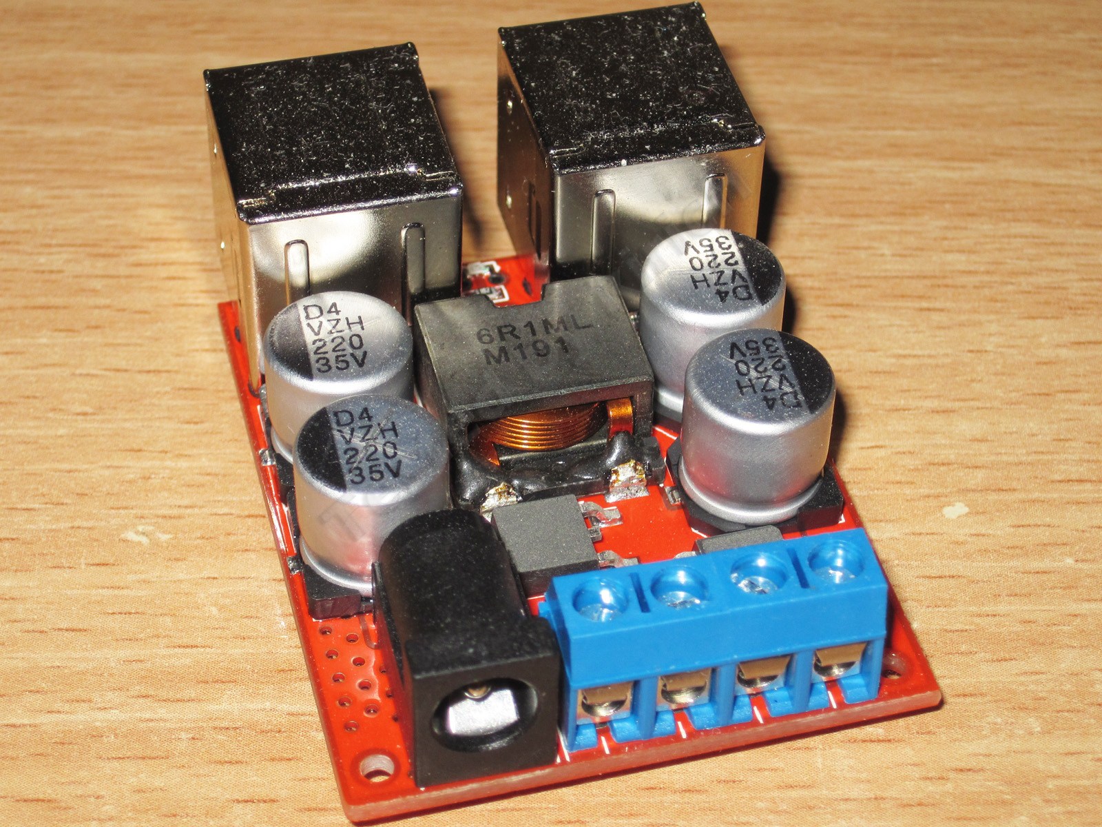
All the other components are on the underside: a fuse, a reverse-polarity protection transistor, the controller, and protective TVS diodes.
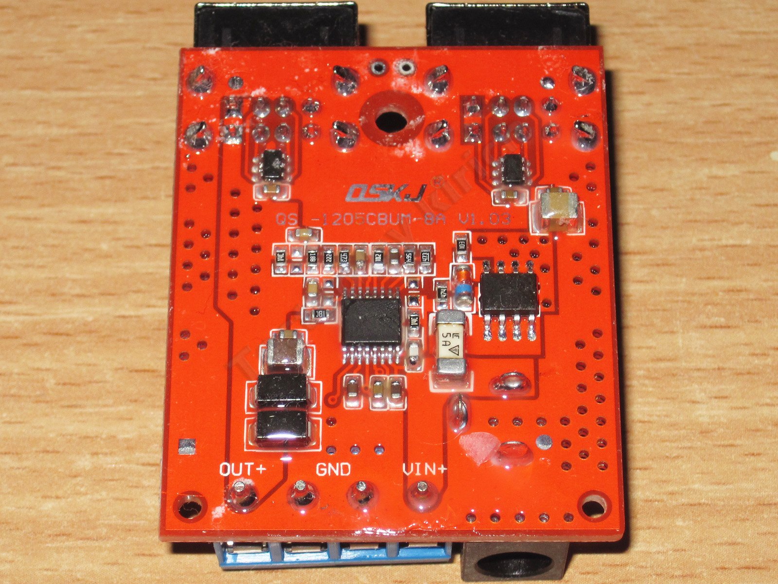
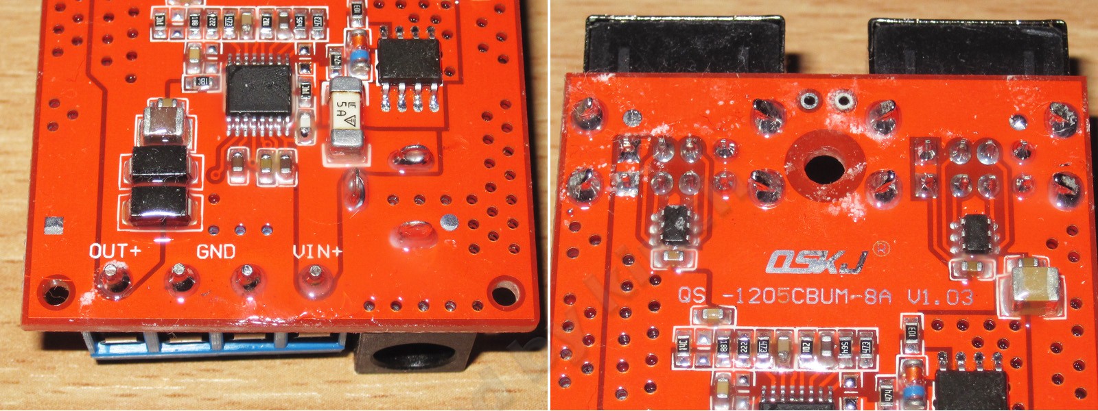
The circuit design is a pleasant surprise. In addition to the fuse, it has proper reverse-polarity protection on the power input, implemented with a MOSFET rather than a diode. I’ve explained how it works before.
It’s also good to see ceramic capacitors on the power rails and two TVS diodes connected in parallel across the 5 V output to protect the load if the power transistors fail. Of course, this protection isn’t a 100% guarantee, but it does improve the odds of the load surviving.
There are controllers on the outputs that set the voltage on the USB data lines so the load can draw the maximum current. It’s not QC, but it does improve compatibility with different devices. Besides, QC on a converter with more than one output requires a corresponding number of converters.
I’ll also note that ceramic capacitors are connected in parallel with the power contacts of the USB ports.
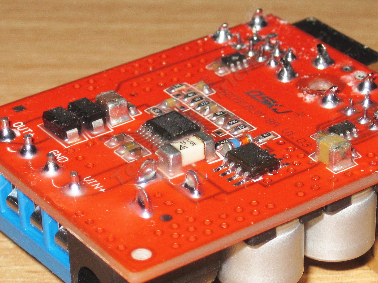
And that’s not all: to improve reliability—or, more precisely, resistance to external influences—the manufacturer coated the board with a rubber-like compound, which is extremely rare.
I connected a power supply. A small red SMD LED indicates that the output is live; if needed, you can replace it with a standard LED, as there are holes for one right next to it.
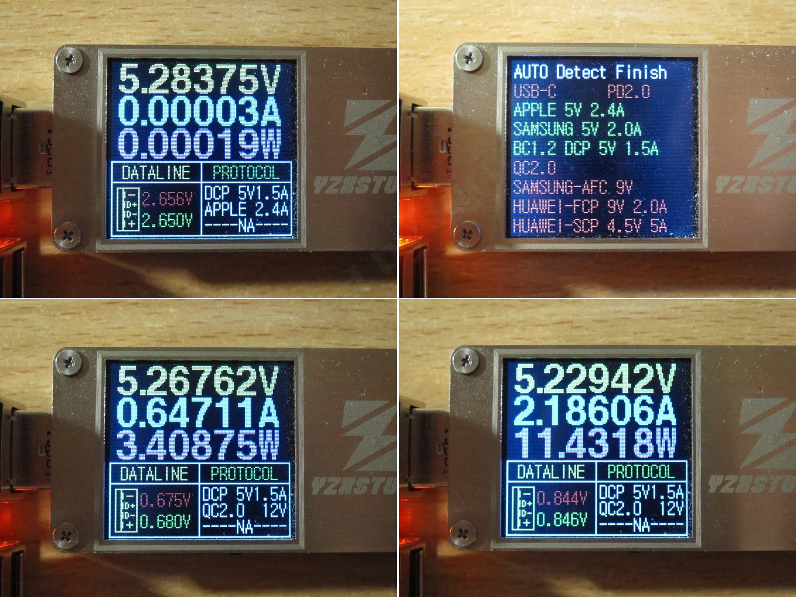
1. The output voltage is 5.28 V, slightly above the standard’s tolerance of 4.75–5.25 V, but not by much, and I don’t think it’s critical.
2. Several emulation modes are supported. Curiously, during my first tests one output consistently showed QC 5 V mode, but when I started preparing the review later and repeated the tests, I couldn’t get it to do that again...
3. When I connected a Samsung phone, the charging current was 650 mA. Apparently, they couldn’t “agree” on a higher rate.
4. On the other hand, when I tried connecting a Chinese UMIdigi, it drew 2–2.18 A without any problems, even though my usual charger won’t charge it properly at all.
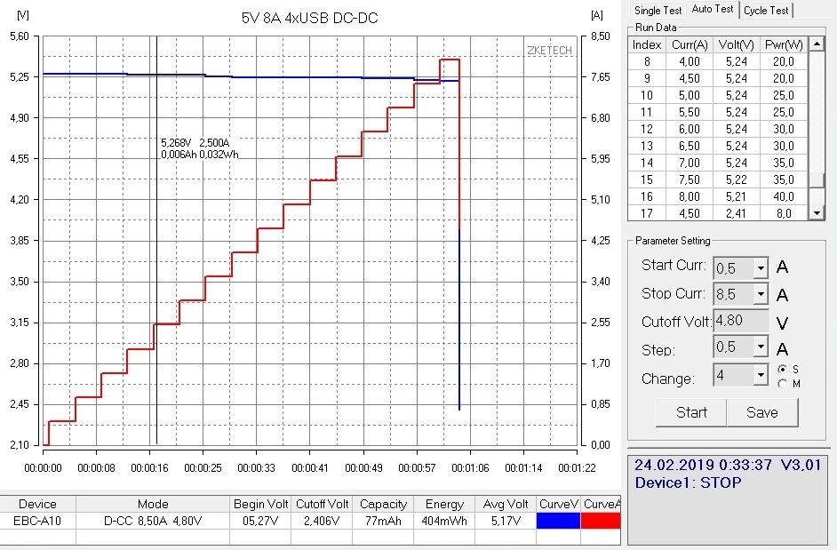
The load test revealed two things:
1. The voltage regulation is good: from zero current up to the maximum load, the voltage drops by just 60–70 mV. The load and voltage were measured at the terminal block, not at a USB port.
2. 8 A is the maximum output current; beyond that, the protection trips. Sometimes it also tripped at a lower current—for example, at that same 8 A.
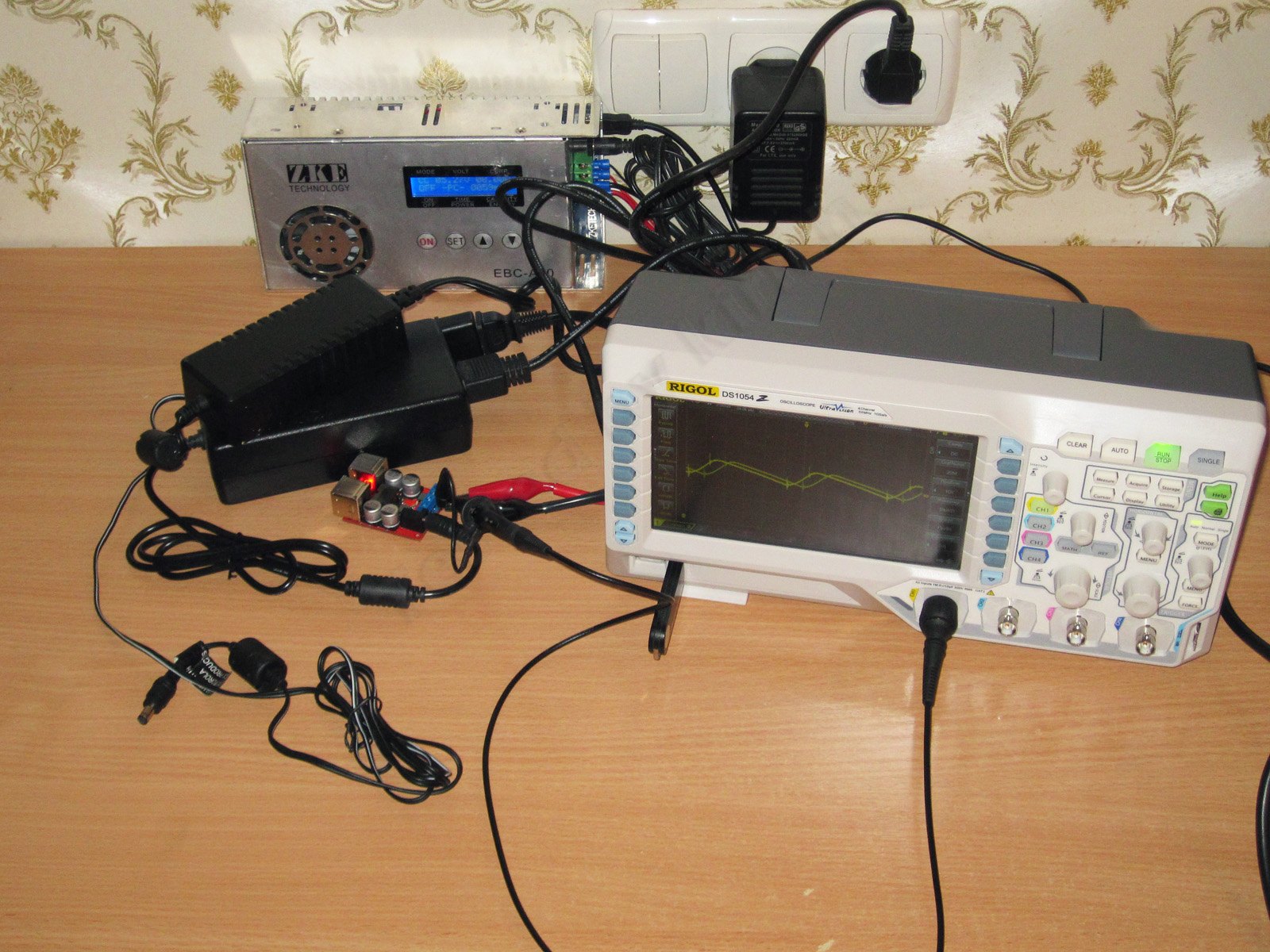
I used the same “test setup” as before to measure ripple, though a few things were different this time. To reduce interference from the measuring instruments, I powered the load from a transformer-based power supply.
Also, since I have two new electronic loads on the way, I’m planning to modify my main one later: move it into a different enclosure, install a transformer-based power supply instead of a switching one, and add galvanic isolation to the computer interface. These modifications should eliminate the possibility of ground loops.
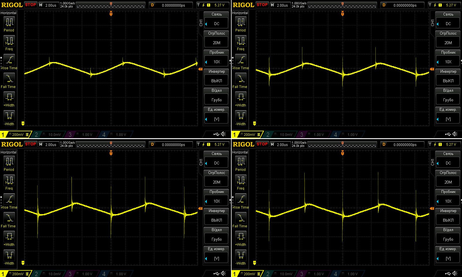
I wouldn’t call the ripple small, though. The main component, which is harder to suppress, is 180 mV in every operating mode. The oscilloscope traces show loads of 0-33-66-100%.
There is also ripple in the form of "spikes". It is easier to suppress, but depends on the load current and has a noticeably larger amplitude.
The input voltage here is 12 V.
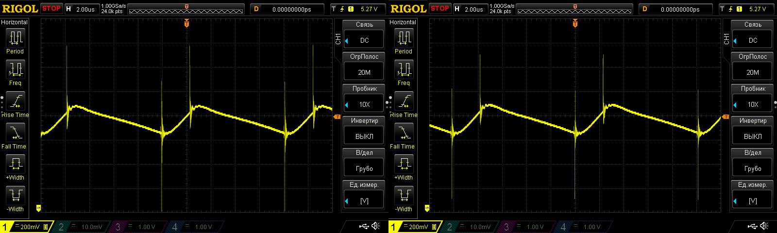
The same test and operating modes, but with an input voltage of 24 V.
Nothing changed except the amplitude of the "spike" ripple. As a simple modification, I’d recommend increasing the capacitance of the output capacitors.

The photo above shows the oscilloscope probe’s ground connected with a wire rather than a spring, which introduces some distortion into the test results. But since the difference isn’t very large in this case, I ignored it.
Input voltage: 24 V; load current: 8 A. Wire on the left, spring on the right.
I checked the temperature in three modes, at load currents of 2.5, 5.0 and 7.5 A. The first test ran for about 10–15 minutes; the thermal camera’s timestamps show the duration of the others.
Overall, the converter handles 7.5 A confidently and doesn’t get too hot, but I wouldn’t put it in a small enclosed box, as it could overheat.

Efficiency measurement. I also measured the no-load current draw. It’s the same at both input voltages: 40 mA.
At an input voltage of 12 V, efficiency is better at low load currents; at 24 V, it’s better at higher currents. You can see this on the graph.

To sum up, I really liked this converter. My only complaint is the ripple level. Otherwise, I think it’s excellent: the build quality, the protection features, output voltage stability and circuit design—all especially impressive considering the price. In my opinion, it’s a very useful piece of equipment for a radio amateur.
That’s all from me. I hope you found the review useful.
usb обогреватель на 5 вольт своими руками, преобразователь 5 в 220 вольт своими руками, купить преобразователь с 5 вольт на 30 вольт, какой кпд преобразователя с 3,7 вольта на usb 5 вольт, фото создать мини преобразователь 3.7в 5в на руками, преобразователь напряжения 5 вольт разводка, преобразователь 5в в 12в, схема преобразователя 5-12, usb 5 вольт 5 ампер, как из 3 вольт сделать 5, транзистор.12.вольт, https://www.kirich.blog/obzory/preobrazovateli/709-preobrazovatel-napryazheniya-5-volt-8-amper-s-chetyrmya-usb-vyhodami, схемы преобразователей с 12 на 5 вольт, 12 вольт в 5 вольт схема, преобразователь уровня 5 вольт в 3,3 вольт на транзисторах, преобразователь 5 в 12 вольт своими руками, конвертер 12 в 5 вольт usb, 12в / 5в преобразователь, преобразователь напряжения 5 в 12 схема, схема преобразователя 12 в 8 вольт, схема зарядка 5 вольт 8ампер, схема преобразователя напряжения с 3.7 до 5 вольт, преобразователь 5в 8а с четырьмя usb выходами, преобразователь 3.7 в 5 вольт своими руками, преобразователь напряжения с 2 вольт до 6, преобразователь напряжения с usb, преобразователь с usb, преобразователи напряжения отзывы, обзор преобразователя напряжения
Questions and answers
How much current can the four-port USB converter deliver?
Its maximum output current is 8 A, after which protection trips. It handled 7.5 A confidently, but the author advises against putting it in a small closed enclosure because it could overheat.
What are the ripple and voltage stability of the 5 V 8 A converter?
The main ripple measured about 180 mV. Voltage dropped by only 60–70 mV as load increased from zero to maximum; measurements were taken at the terminal block.
Does the board have protection and QC fast charging?
It has a fuse, reverse-polarity protection and output TVS diodes. QC is not specified: USB controllers adjust the data-line voltages, but compatibility varies between phones.
The figures from this review are in the measurement database: Converters
Discounted products
You may be interested in


Discounted products
All the content on the site and the advice are free, but we’d be grateful for your support of the project and the channel!
Comments5
Only registered readers can comment. It takes a minute to sign up, and you can log in with the same account you use on the forum.
Log inRegister
Comments are published in their original language.