
Atorch BW600 load switching board
A reminder: to keep up with new posts on the blog, I recommend following me on Instagram. I’ll post notifications about new articles there and maybe write about something interesting now and then: link to my account
You can also subscribe to updates and new articles on the Telegram channel - https://t.me/KirichBlog Note that discussions of reviews and articles are enabled on the channel, along with general chat. I recommend it.
But it’s not quite that simple. I ordered the board in early December, and even managed to test it before New Year’s, but then one thing led to another and I forgot about it. I was reminded of it quite recently, when I found out that this board had been discontinued and replaced with another one.
Why did I decide to publish a review of a discontinued board? Well, at the very least, because you can still find it for sale. I’ve seen it in Ukraine, and it may still be available on AliExpress too.
First, some background. I tested two older versions in detail here, but let me recap.
The first version switches the power using only a transistor. Reverse-polarity protection consists of a fuse and a diode. If you connect the charger the wrong way around, the designers intended for the fuse to blow. But it won’t, because a charger usually regulates its current.
For the second version, the designers scratched their heads and realized this was a fail. They scratched their heads again and came up with an even bigger fail: they put a diode in series, causing a large voltage drop. Not only did the diode get hot as a stove, but charging problems cropped up too.
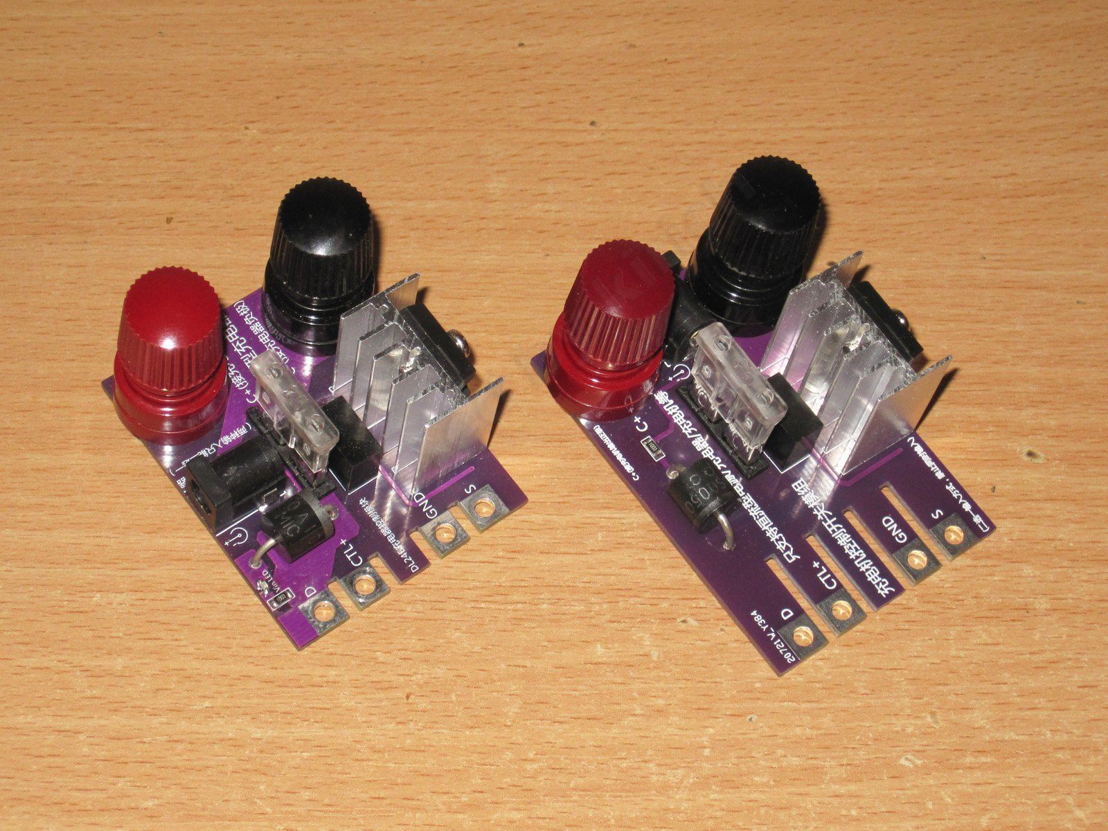
So here we have two clear engineering mistakes that even an amateur could spot. And that’s not counting the transistor overheating, the lack of proper reverse-polarity protection, or the fact that the circuit doesn’t fully disconnect.
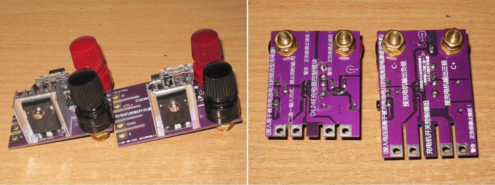
In the end, I never used these boards. For loads with charging control support (mainly the DL24EW), I installed my own DIY boards, which eventually evolved into a production version. Those are what I’m still selling on OLX.
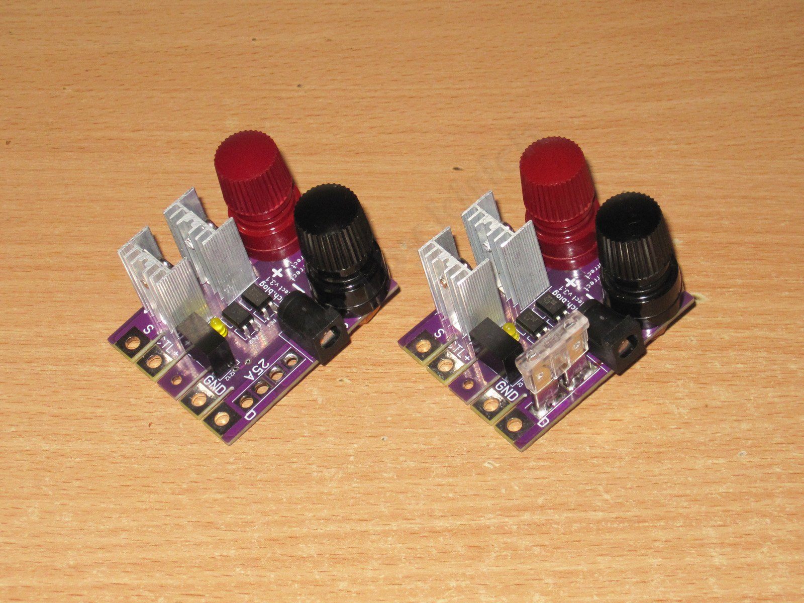
But I just couldn’t stop thinking about Atorch’s new board. I ordered one and received it; this is the updated version, as the first one didn’t have a heatsink.
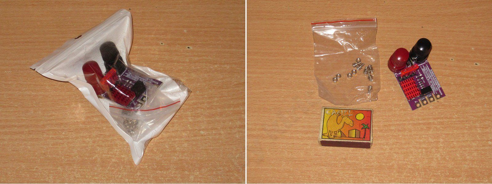
The board is neatly made and about the size of a matchbox.
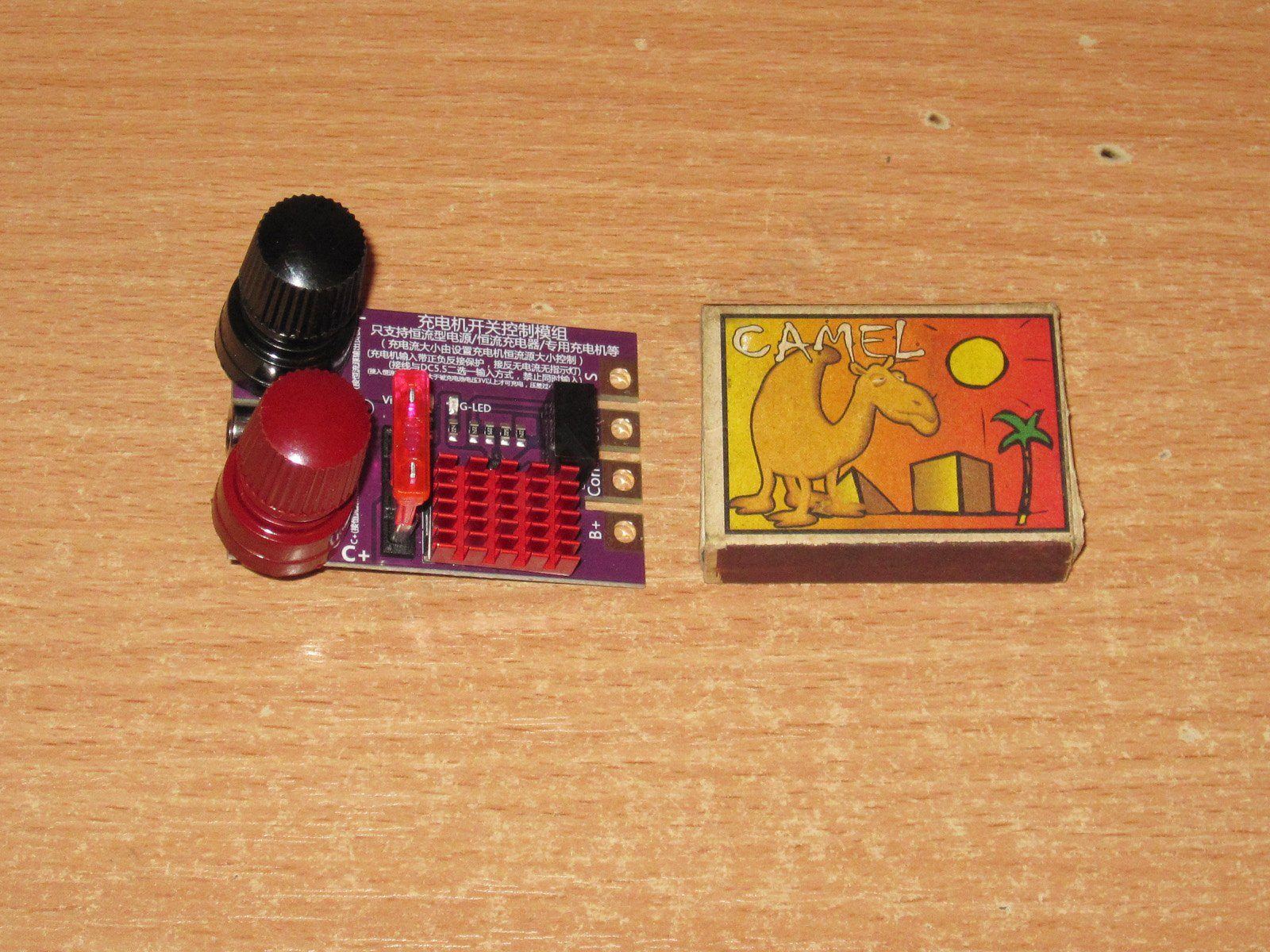
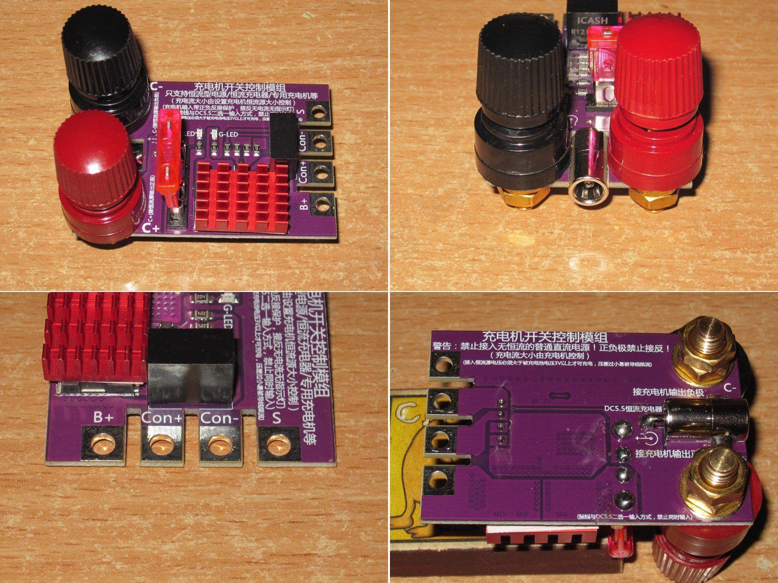
Another noticeable improvement is the new DC connector. I didn’t check whether it’s a 5521 or 5525, but it doesn’t really matter here.
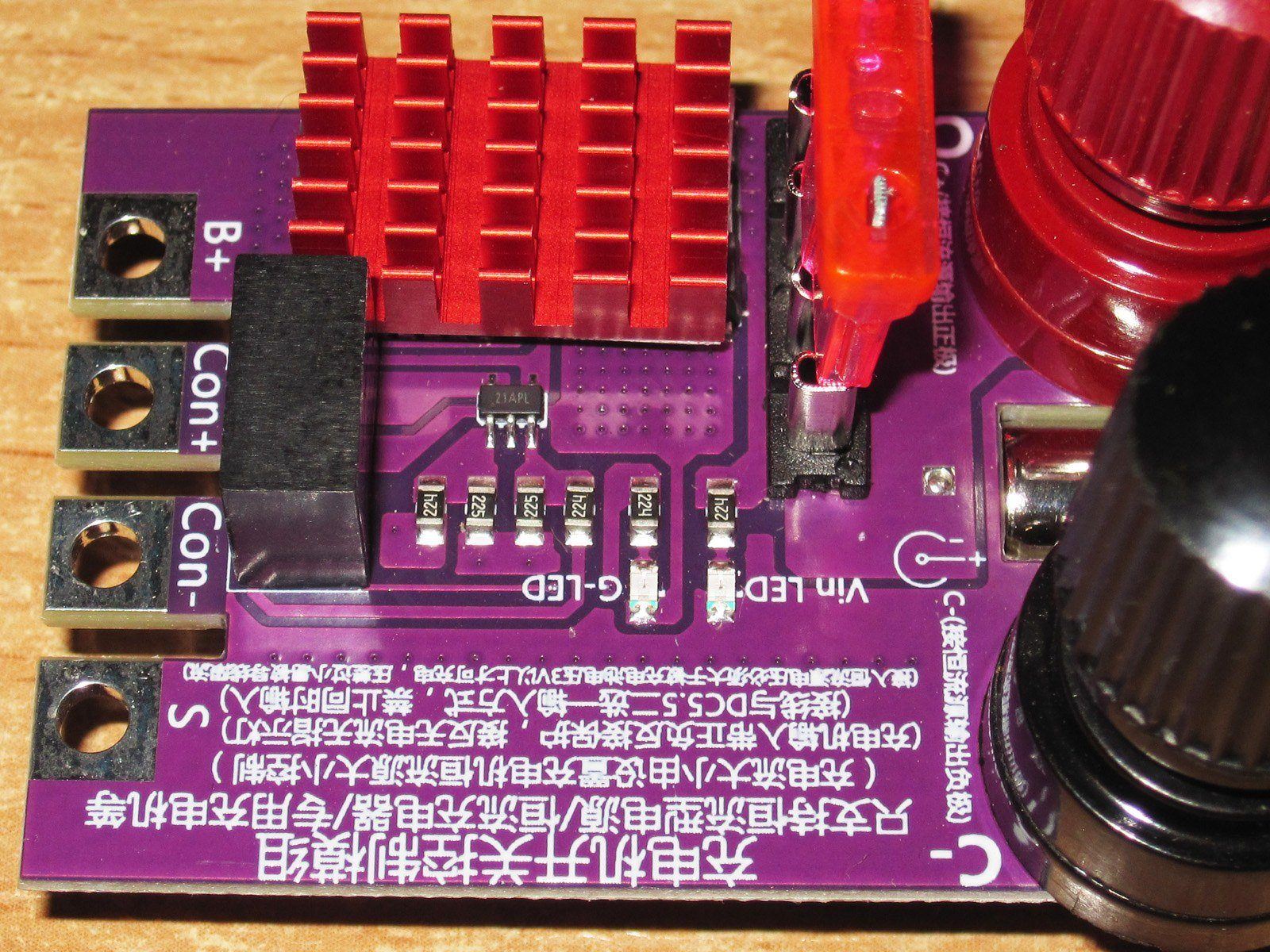
You can also see that the board has become more complex: an op-amp has been added, and the connector layout for connecting to the load has changed.
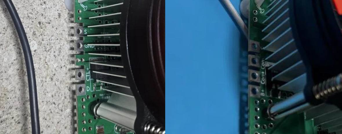
Speaking of the connector layout, in my review of the new load I wrote that the BW600’s switching board connection had changed. The old board had two contacts, a gap, then two more contacts; the new board has four contacts in a row. The order, however, is unchanged.
So the boards are electrically compatible, but not mechanically compatible. To use one in place of the other, you have to connect it with wires.
This caused me some problems. My listing said that my boards were compatible with the DL24EW, CL24, and BW150 loads, but some time later the designers changed at least the BW150 boards, and mine no longer fit. So now I always ask which version someone has.
On the left is the old version, on the right the new one. In both cases it’s the same load: the first was bought a long time ago, the second recently.
Back to the new board: an op-amp and its supporting components have been added, while galvanic isolation has been retained. It won’t work without it, because all switching is done on the positive power rail.
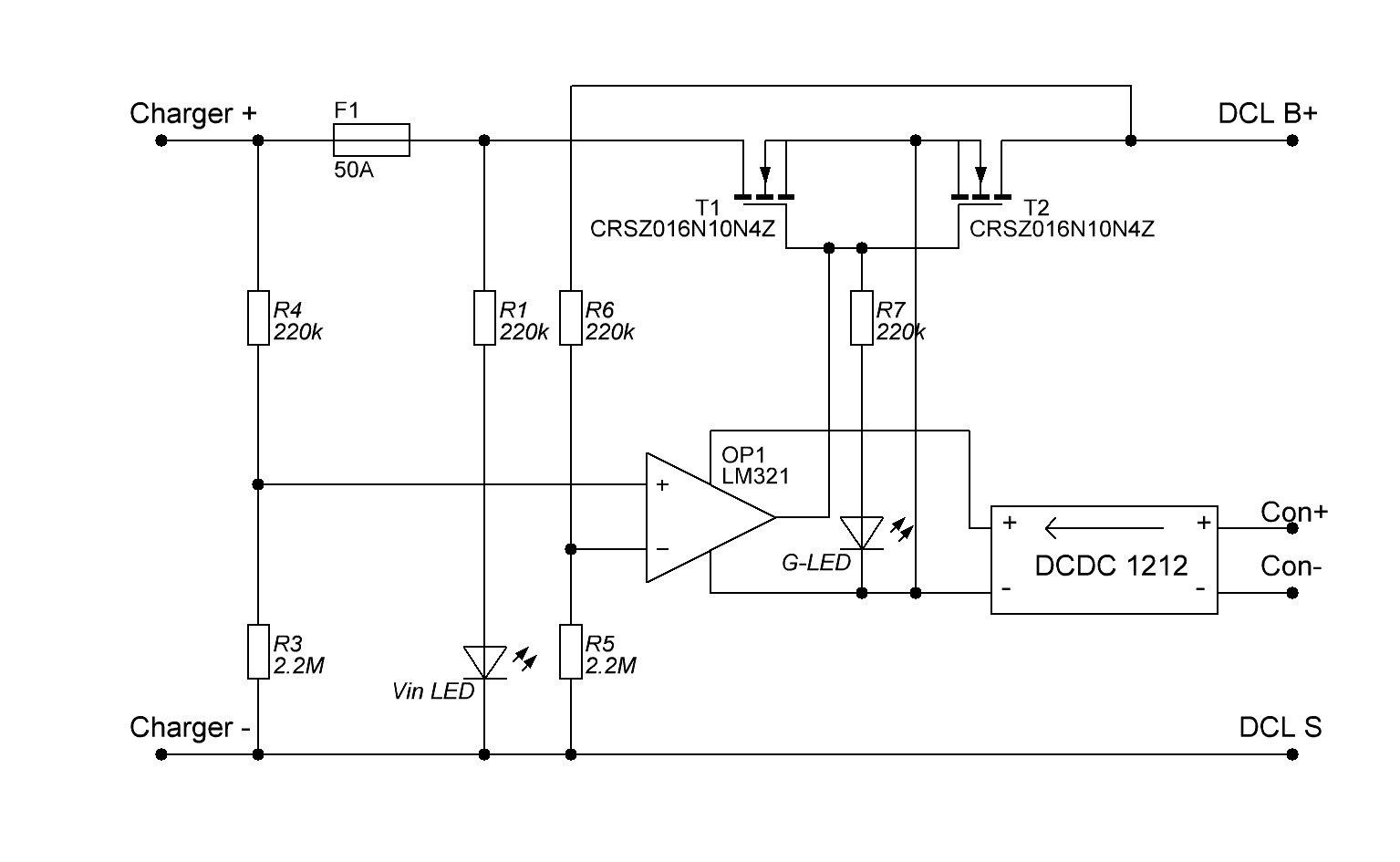
To save you a lengthy explanation, I redrew the switching circuit.
The principle is very simple, and the designers got this part right. First, they made the power stage like mine (coincidence?), so it fully disconnects the circuit. Second, they used the op-amp in a way that turns a drawback into an advantage.
The point is that an op-amp has what’s called offset voltage—in essence, a dead zone. So here it provides a trigger effect: if the op-amp drops below this voltage, it holds its previous output state. You can switch it by applying a voltage higher than the Offset to the other input.
In short, it’s a very elegant solution. I use a different approach—cruder, but it works just fine.
In the end, both versions—mine and Atorch’s—provide complete isolation and reverse-polarity protection on both sides.
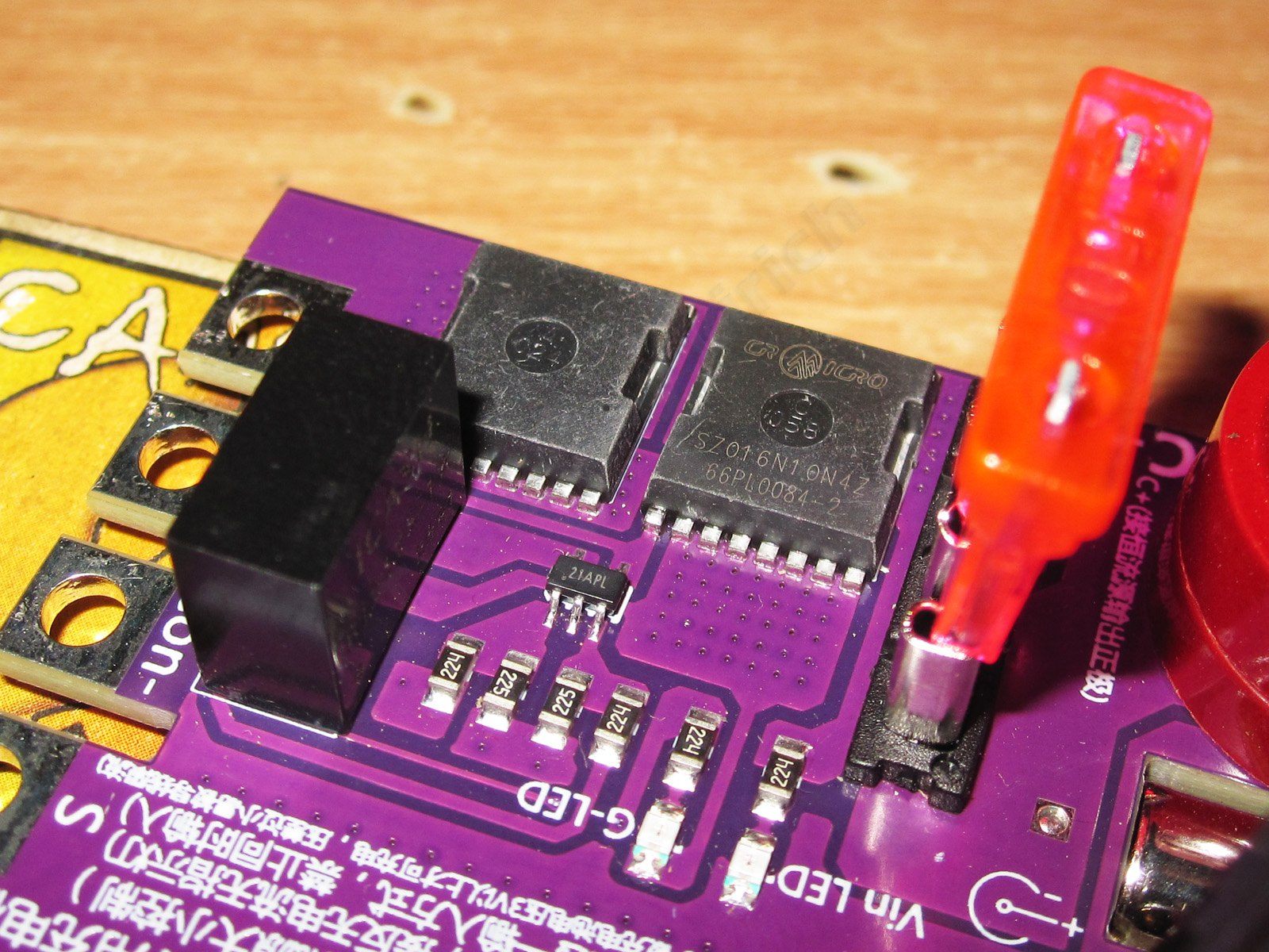
I also liked the transistors they used. The ones I use are clearly inferior.
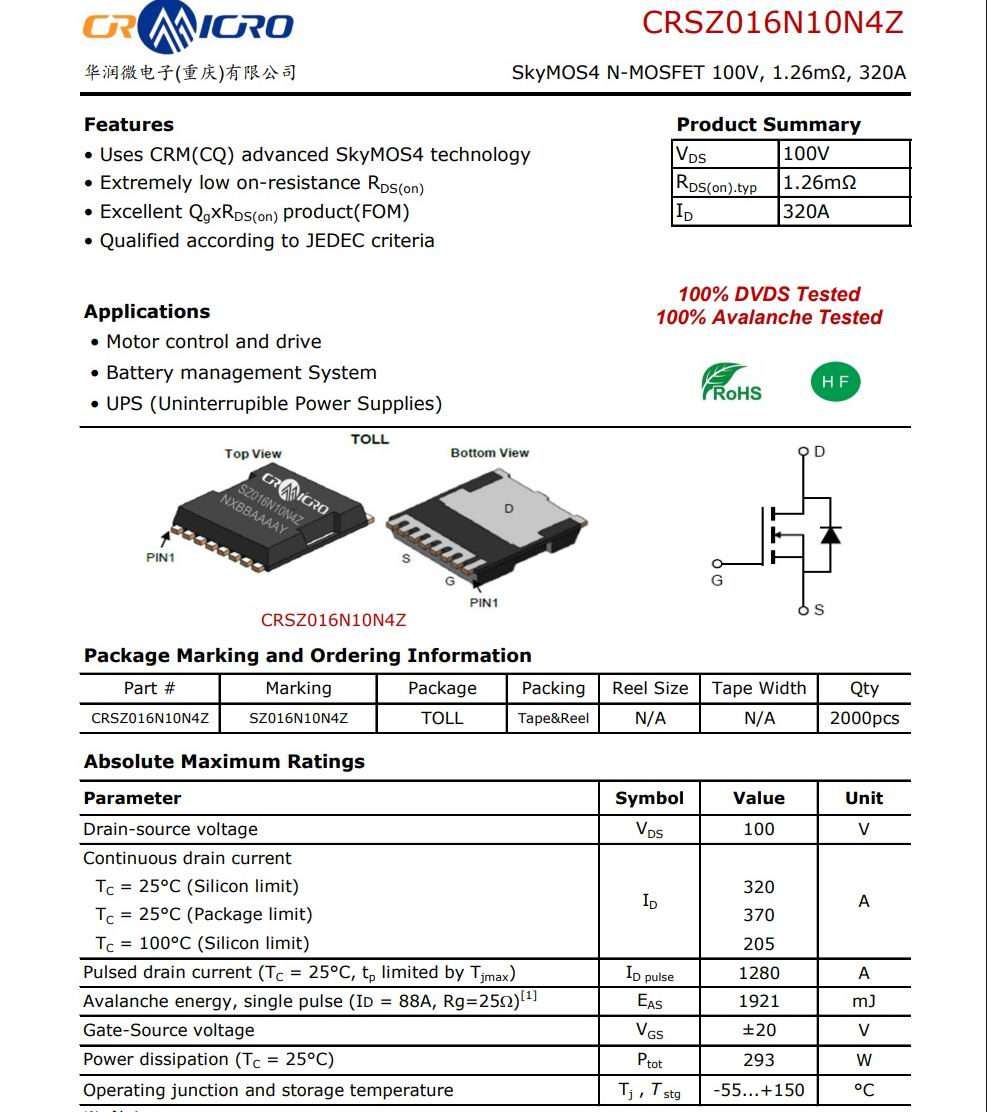
These transistors are also rated for 100 V, but their resistance is almost three times lower: 1.26 mΩ versus 3.5 mΩ. That directly affects heat and voltage drop.
Speaking of voltage, Atorch is being a little misleading here. Yes, technically the switching stage can break a circuit carrying up to 100 V, but you really shouldn’t use it with batteries above 50–55 V—same goes for mine.
The thing is, if you reverse the polarity of a battery or charger above 50 V, the battery and charger voltages add up, giving you the full 100 V, which will blow the transistors. If you get the polarity right, then yes, 100 V or even more is no problem—but that defeats the purpose of reverse-polarity protection.
For testing, I put together a small test setup. I had to use two power supplies, since the Atorch board can’t run in self-latching mode.
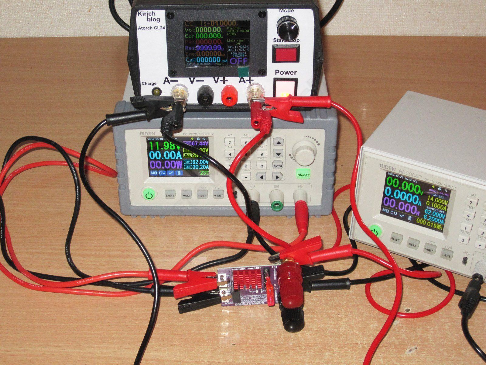
I also ran into some trouble starting it under load and had to experiment a bit, but that has nothing to do with normal operation. The problem was getting it started without the load board, due to how the op-amp stage works.
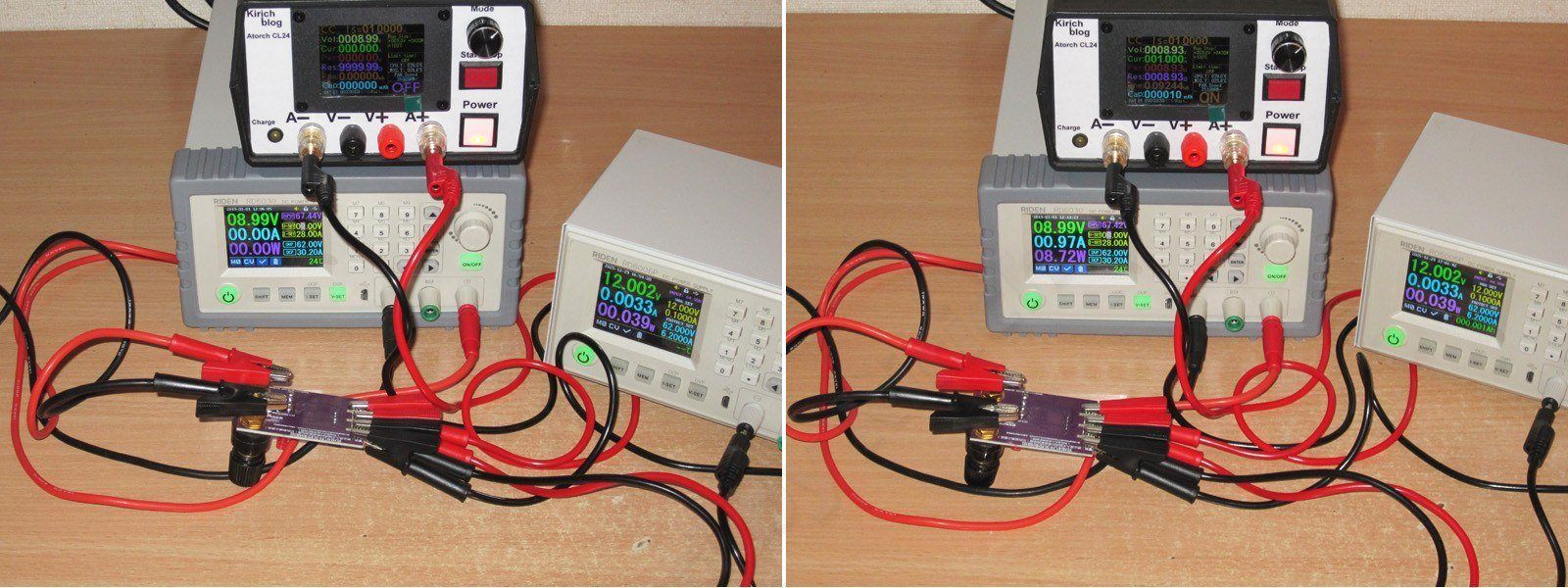
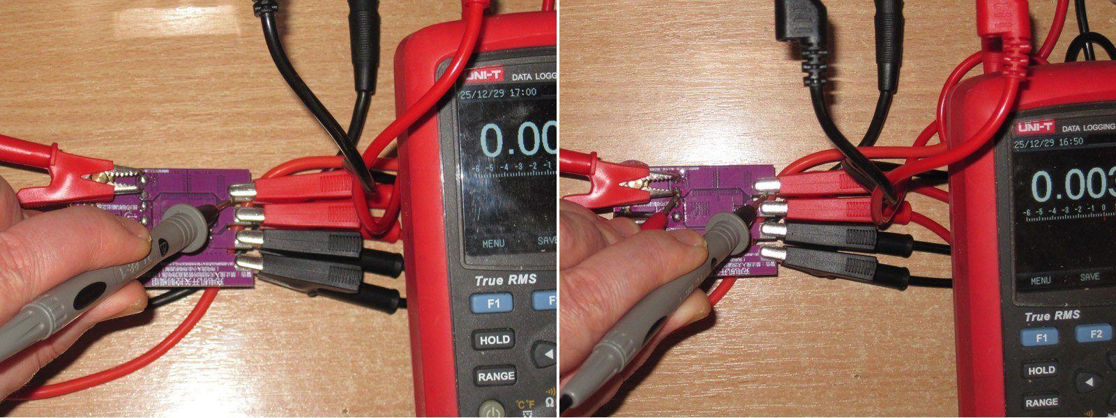
Last time I measured two voltages, on the negative and positive rails. This time I took three measurements: one on the negative rail and two on the positive rail.
The point is that my board has the fuse on the negative wire and the switching on the positive wire. On this board, the fuse is on the positive side, along with the switching stage, while the negative wire passes straight through. The overall setup is much the same; the third measurement was mostly an extra one to see how much voltage drops across the transistors.
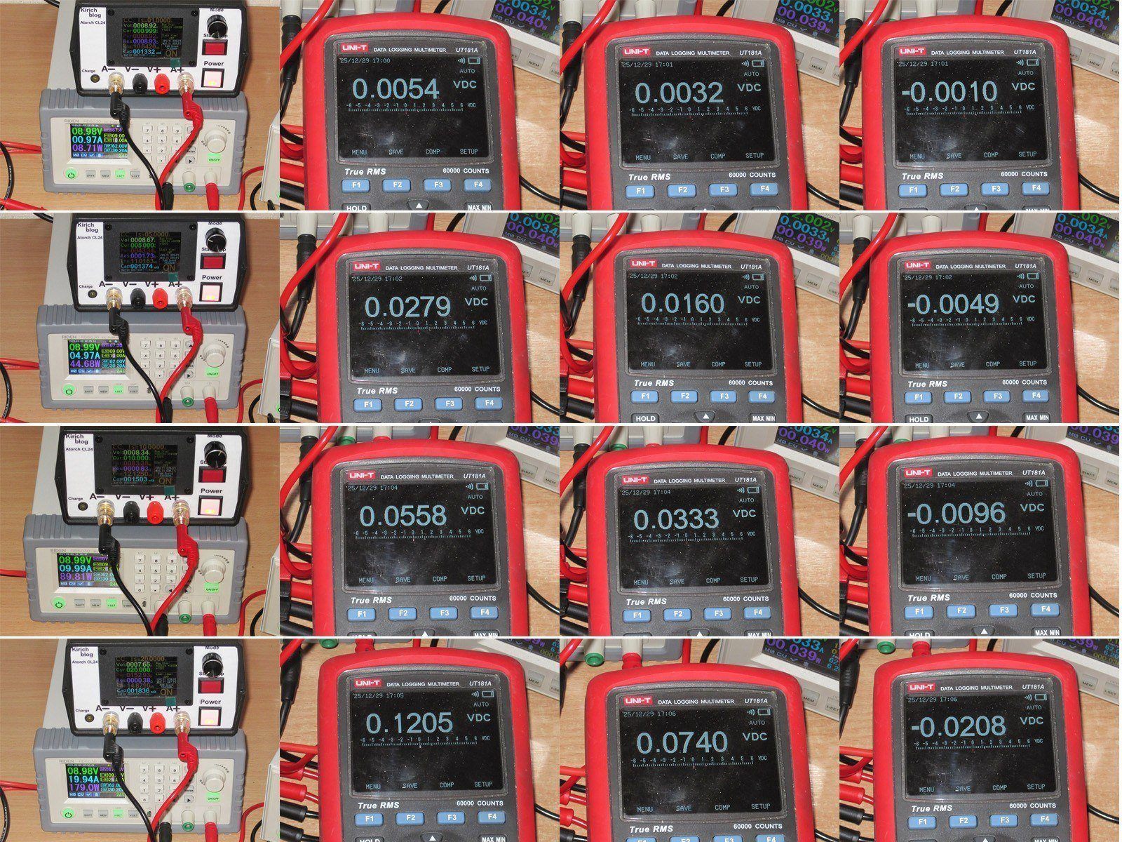
Measurements were taken under the same conditions, at currents of 1, 5, 10 and 20 A. The order in the photo is: current, total drop on the positive side, drop across the transistors alone, and drop on the negative rail.
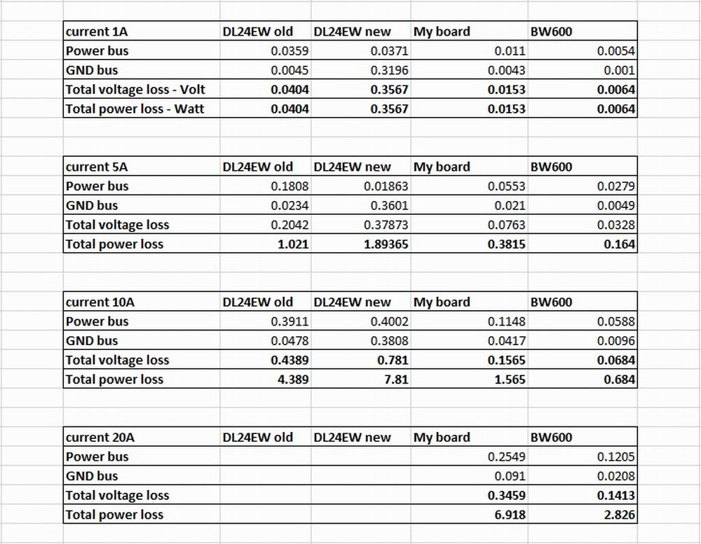
For easier comparison, I put the results in a table. I didn’t use the old boards at 20 A, since even 10 A is too much for them.
The bottom rows show the total voltage drop (critical for charging) and total power loss as heat.
Since the total losses also include the drops across the traces and fuse, the difference compared with my boards came out to less than three times—but it’s still substantial: almost 7 W versus 2.8 W for the new Atorch board.
The transistor temperature at 20 A stayed below 70 °C, which is excellent.
Needless to say, I really liked the new board. My customers can vouch for that: once it came out, I recommended it for new versions of my electronic loads and shared the link.
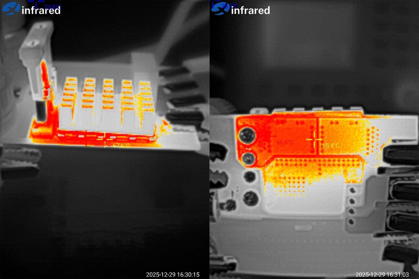
But recently I spotted a new version of the BW600 board for sale. It has the same claimed 100 V rating and 20 A current rating, but something has clearly changed. At the very least, there are now two terminal options. They send them at random, but I’ll say right away that I prefer the ones on the right.
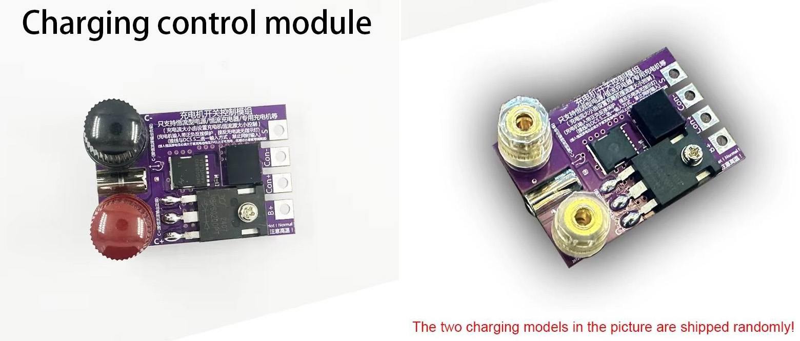
But wait—where did one of the transistors, the heatsink and all the other bits go?
Then I realized they’d basically gone back to the second-version board, where the diode was connected in series and the transistor was simply switched by the DC-DC converter—only now they’ve used a better transistor and diode. They even removed the fuse. I wouldn’t say it’s absolutely necessary there, but the point is, they’re selling this board for only a little less than the one I showed above, even though they’re completely different boards.
So now we’re back to having a voltage drop across the diode, not to mention that at 20 A it’ll get hot as a stove. Making the same mistake twice—how do you even...
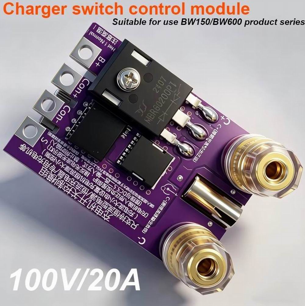
Conclusions.
Atorch released a great board in the new revision. I genuinely liked it. I even thought, “No way—is this a dream? They made a board better than mine, damn...” And then they decided that we'd done something too well, that this couldn't be right, and released this stub....
So, the link and price are for the new board. You can look for the old one on Prom or at Radiomag (they had good prices). If anyone needs one, I recommend buying it while they're still available.
In theory, there may have been some issues with the third-version board, with its two transistors, but I didn't find anything during testing.
My board's logic is a little different: the transistors only turn on if there is voltage above a certain level on both sides, with the correct polarity. But the switching circuit on the third-version boards is better than mine, while the fourth-version board is just strange.
Questions and answers
What is good about the third-revision Atorch switching board for BW600?
It fully disconnects the circuit and protects against reverse polarity on both sides. Its transistors have an on-resistance of 1.26 mOhm, compared with 3.5 mOhm for the author's transistors.
Can the Atorch board for BW600 be used with a 100 V battery?
With correct polarity, the switching stage can handle up to 100 V, but the author advises staying below 50–55 V: reverse polarity can add the battery and charger voltages together and damage the transistors.
How does the simplified new Atorch board differ from the third revision?
The simplified board removes a transistor, the heatsink, and the fuse, and puts a diode in series. The author notes that this again causes a voltage drop and diode heating at 20 A.
The figures from this review are in the measurement database: Other devices
Discounted products
You may be interested in


Discounted products
All the content on the site and the advice are free, but we’d be grateful for your support of the project and the channel!
Comments6
Only registered readers can comment. It takes a minute to sign up, and you can log in with the same account you use on the forum.
Log inRegister
Comments are published in their original language.