
Two almost slim power supplies rated at nearly 400 W, 12 and 24 V
A couple more power supplies, quite attractive and relatively well made, at least on the outside, but with typical Chinese “quirks” in exaggerated form—at least one of them.
A reminder: to keep up with new posts on the blog, I recommend following me on Instagram. I’ll post notifications about every new topic there, and might also write about something interesting now and then - link to account
You can also subscribe to updates and new articles on the Telegram channel - https://t.me/KirichBlog
Even at first glance, you notice the packaging. It’s not the usual plain white or gray box, but one with full-color printing. The Chinese are certainly good at making things look impressive, but to be fair, it really works: if a store shelf has two boxes, one plain gray and one attractive, the customer is much more likely to choose the latter.

I’ll start with the smaller one, which is rated at 12 V, 33 A, and 400 W on the case.
It looks nice, but somehow... clearly not like a 400 W unit. The case measures 230 × 34 × 24 mm.

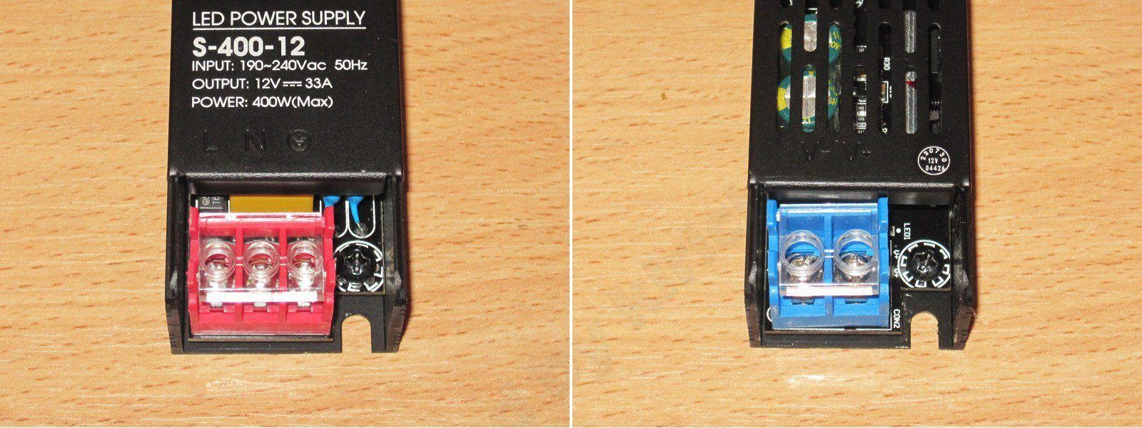
There are terminal blocks with neat little covers at both ends. I’d give them five stars if not for one detail: there’s a screw to the right of the terminal, and the board is well supported there, but on the left there’s neither a screw nor a support. When you tighten the screw, the board bends noticeably.

Getting inside is very easy; you just need to remove the top cover.

The input has a filter, a fuse, and a thermistor. The input capacitors are rated at 68 µF, 400 V, two of them. That’s clearly too little for 400 W. It’s also obvious that this power supply uses a flyback topology, which means there’s no way it can deliver 400 W with a transformer like this—not even 200 W. Maybe 150 W.

On the output side, there are a pair of diode assemblies, three capacitors, and a handful of other components.

The input capacitors add up to 2 × 68 = 136 µF, but the actual measured capacitance is 87 µF—not much. By the way, this power supply is rated for an input voltage starting at 190 V. I’m almost certain it will also work from 115 V, with some reduction in power.
The output side is fine; the installed 3000 µF is all there.

I took it apart further after the tests, to make sure the testing was done correctly, but I’ll show that part now.
There are a couple of thermal pads under the board: one near the high-voltage transistor, the other near the transformer’s output pins. I don’t understand why they didn’t put a pad under the transformer.

The PWM controller section is neatly soldered, and the board is coated with varnish. Definitely a win here.

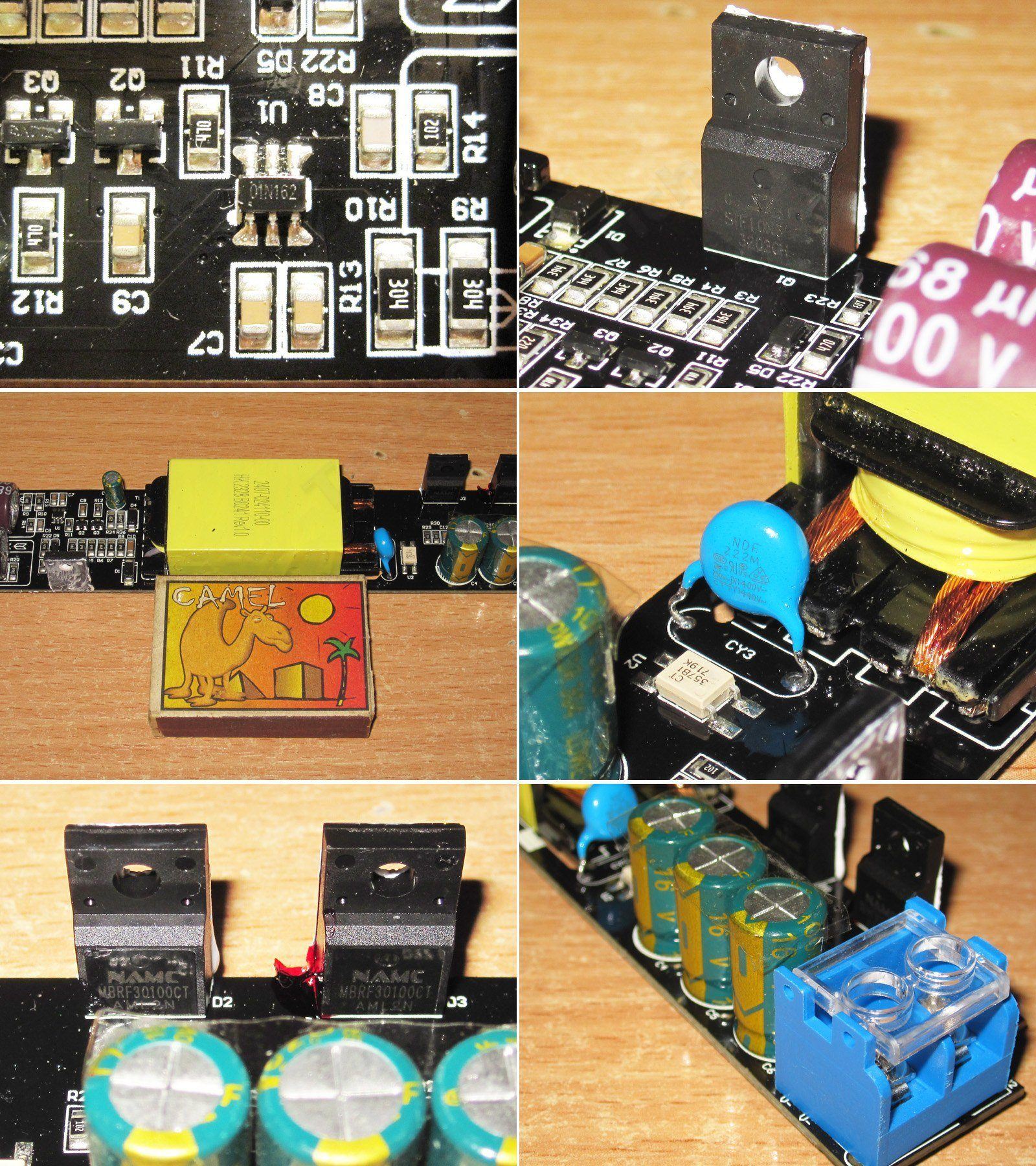
1. PWM controller. To the left, you can see a pair of emitter-follower transistors driving the high-voltage transistor—a good solution.
2. 10N60 transistor, rated at 10 A and 600 V according to the markings.
3. The transformer is actually not that small, by the way. I especially like its long, narrow design; in theory, it should dissipate heat well.
4. The interwinding capacitor is the right type. The transformer is wound with a bundle of many thin wires, which is also good.
5. The output diode assemblies are rated at 30 A, 100 V, and are connected in parallel, giving a current capacity of up to 60 A. No complaints here either, given the actual power rating.
6. As expected, the output capacitors are rated at 16 V. Too bad.

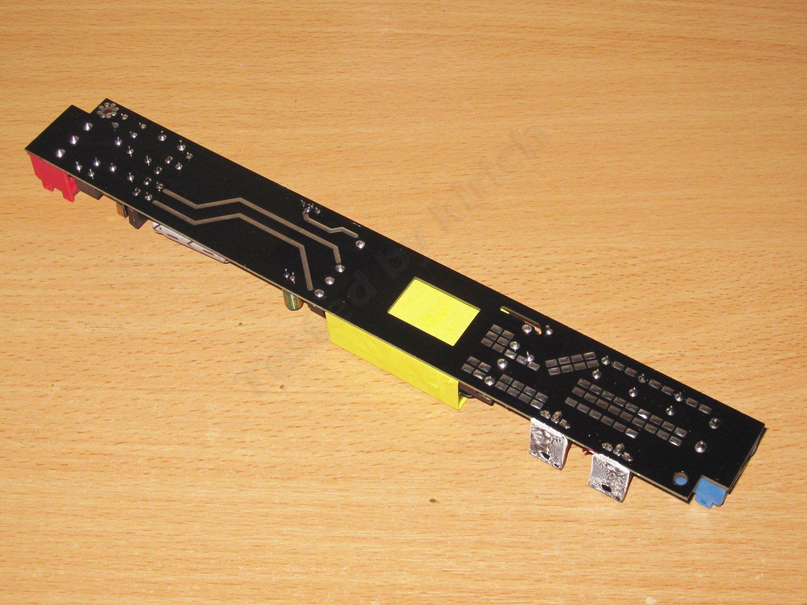
The underside is just as neat. There are no components here, but the board is clean. There’s a “window” under the transformer that’s practically begging for a piece of thermal pad.

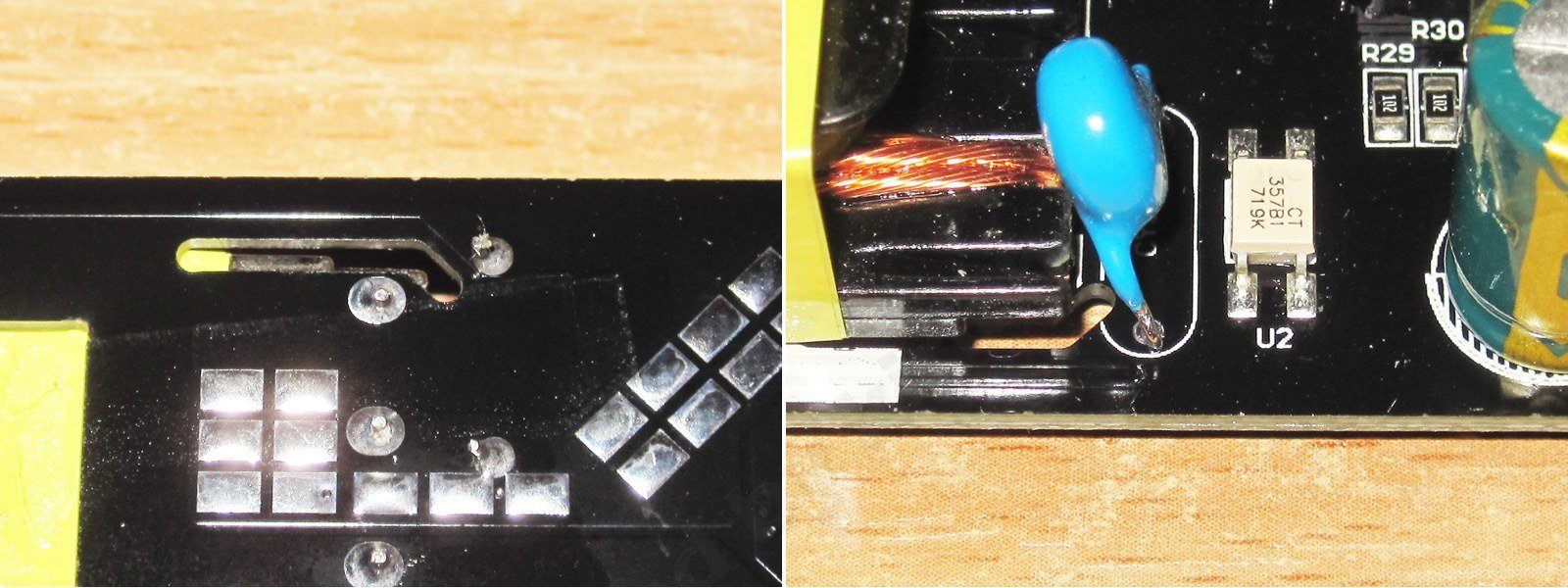
There’s a gap around the interwinding capacitor, so no issues there. I also didn’t spot any narrow clearances around the optocoupler, although it’s quite difficult to make out anything on the black board.

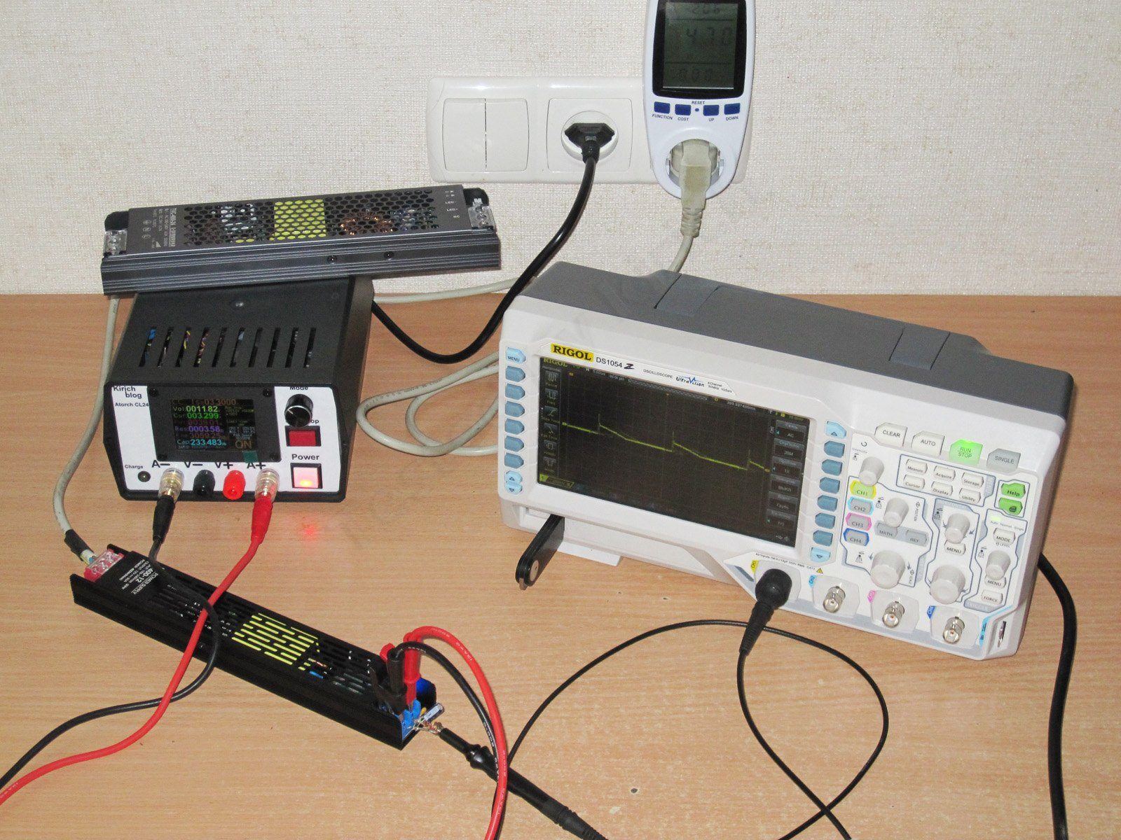
And of course, the tests: power, ripple, and temperature rise. Judging by the markings, this really calls for a higher-current load, but the reality turned out to be much simpler.

While measuring efficiency, I found a few other things:
1. No-load voltage: 11.91 V
2. Maximum continuous current is about 10 A; the protection trips at 11 A.
3. At 10 A, the voltage drops to 11.885 V, which is actually pretty good.
4. Efficiency is around 84%, an average result.

Ripple. A flyback power supply with no output filter, so the ripple is usually relatively high.
But I have to say, for a flyback PSU without a filter, it’s really not that bad:
1, 2. No load; ripple is visible only at low frequencies, which is normal.
3, 4. 5 A load: the main high-frequency ripple is around 120 mV, but there are some pretty large “spikes.” Low-frequency ripple is fine.
5, 6. 10 A load: around 180 mV at high frequencies. It would be great if not for the “spikes”—an output inductor is clearly called for. Low-frequency ripple is basically fine.
I’ve written about these “spikes” before. They’re not that bad for the load, since they’ll simply drop across the wires. What makes them undesirable is the noise they radiate and the extra stress they put on the PSU’s output capacitors. Unfortunately, this is a characteristic of single-ended flyback power supplies, to a greater or lesser degree in all of them.

Thermal test.
1. Cold PSU, no load
2. Cold PSU at 3.3 A
3. Warm PSU at 6.6 A
4. Warm PSU at 10 A
5. Hot PSU at 10 A
6. Hot PSU, no load.
The results are very, very good. The PSU’s output voltage is almost unaffected by either the load or the temperature. Kudos.

The thermal test was run at 3.3, 6.6 and 10 A, for about 20–25 minutes at each step. There’s no point showing the results at 3.3 A, so I’ll show the readings at 6.6 and 10 A.
1. At 6.6 A: transformer at 75°C, transistor at 53°C, output diodes at 66°C. Quite good.
2. At 10 A: transformer at 110°C, transistor at 75°C, diode assemblies at 92°C.
Basically, my only concern is the transformer temperature. 110°C is very high, so in my opinion the PSU’s long-term maximum output is around 100 W.

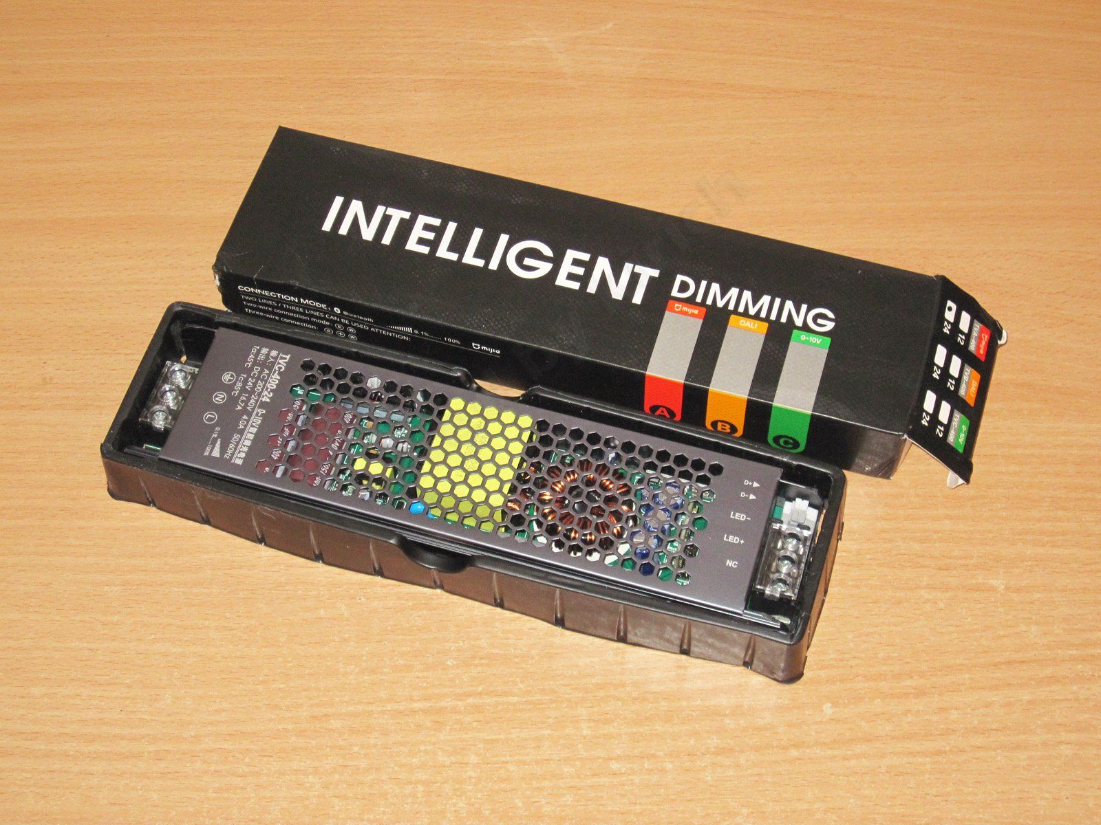
The second model is more interesting. Its rated specs are 24 V, 16.7 A, 400 W.
The packaging is even fancier here; there’s even a special tray for the power supply itself.

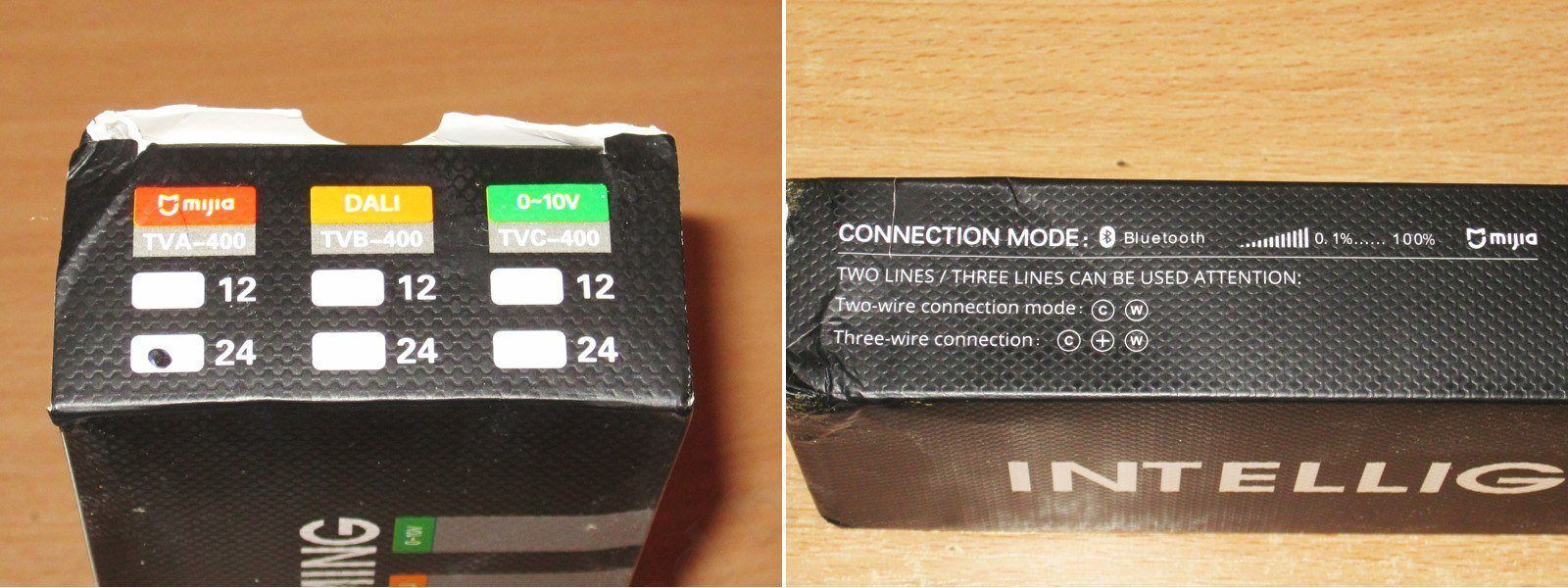
What makes it more interesting is that it lets you control the power delivered to the load. It supports three control methods; this review covers the simplest one, using a 0–10 V control signal.

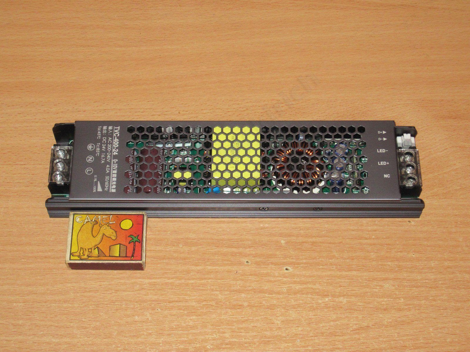
It’s clearly larger at 250 × 60 × 29 mm, and feels noticeably heavier in the hand.

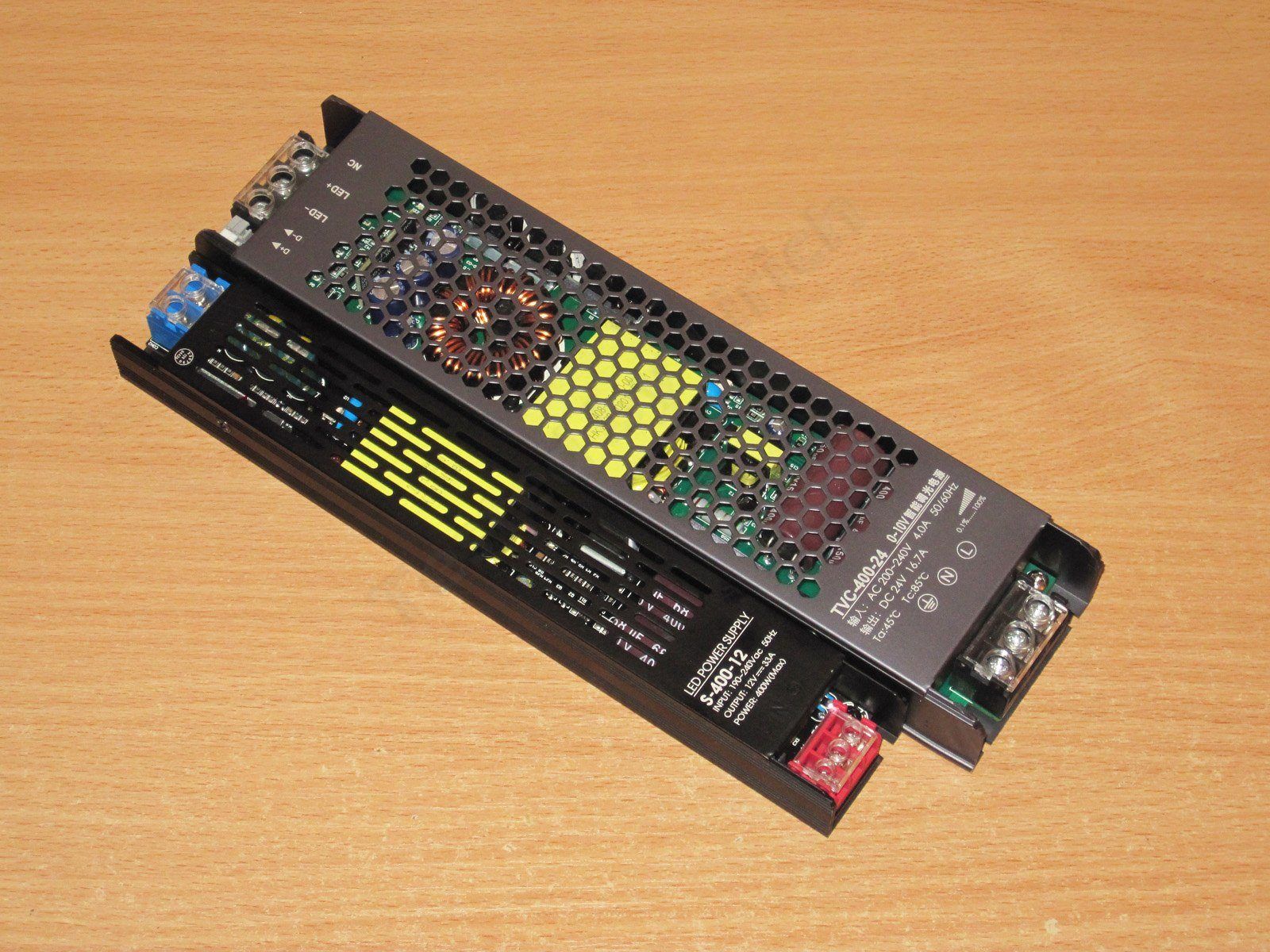
Here it is next to the previous model. The funny thing is that both have the same rated power: 400 W :)

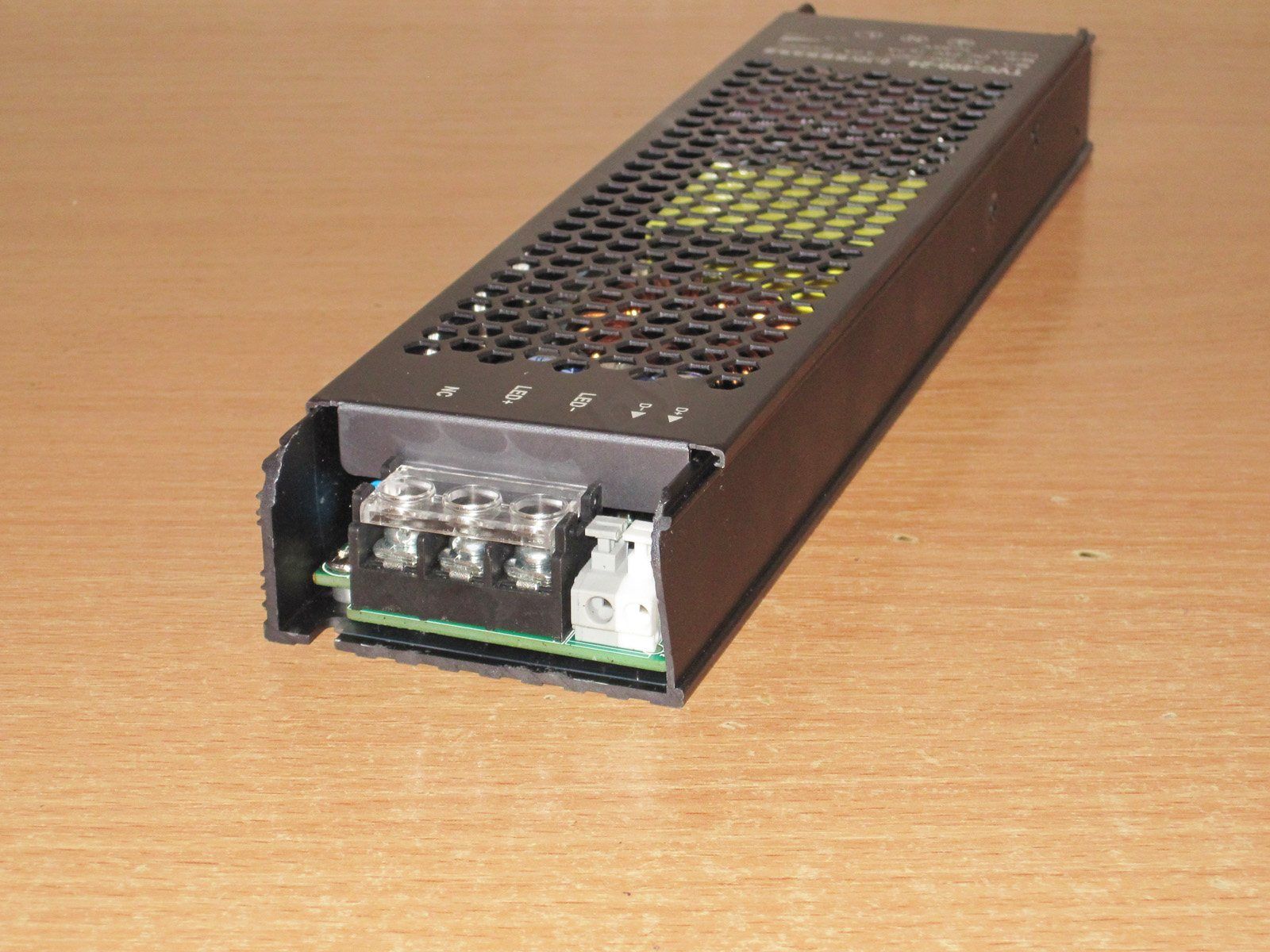
The terminal blocks are the familiar type, with protective covers. There are three mains input terminals on one side, and the load and control signal connections on the other.
The power terminal block has three contacts, one of which is marked NC. We’ll come back to that.

This particular unit seems to have had a rough trip somewhere along the way: the case is slightly bent. Fortunately, it’s not bent on the side with the power components, so it’s not a major issue.

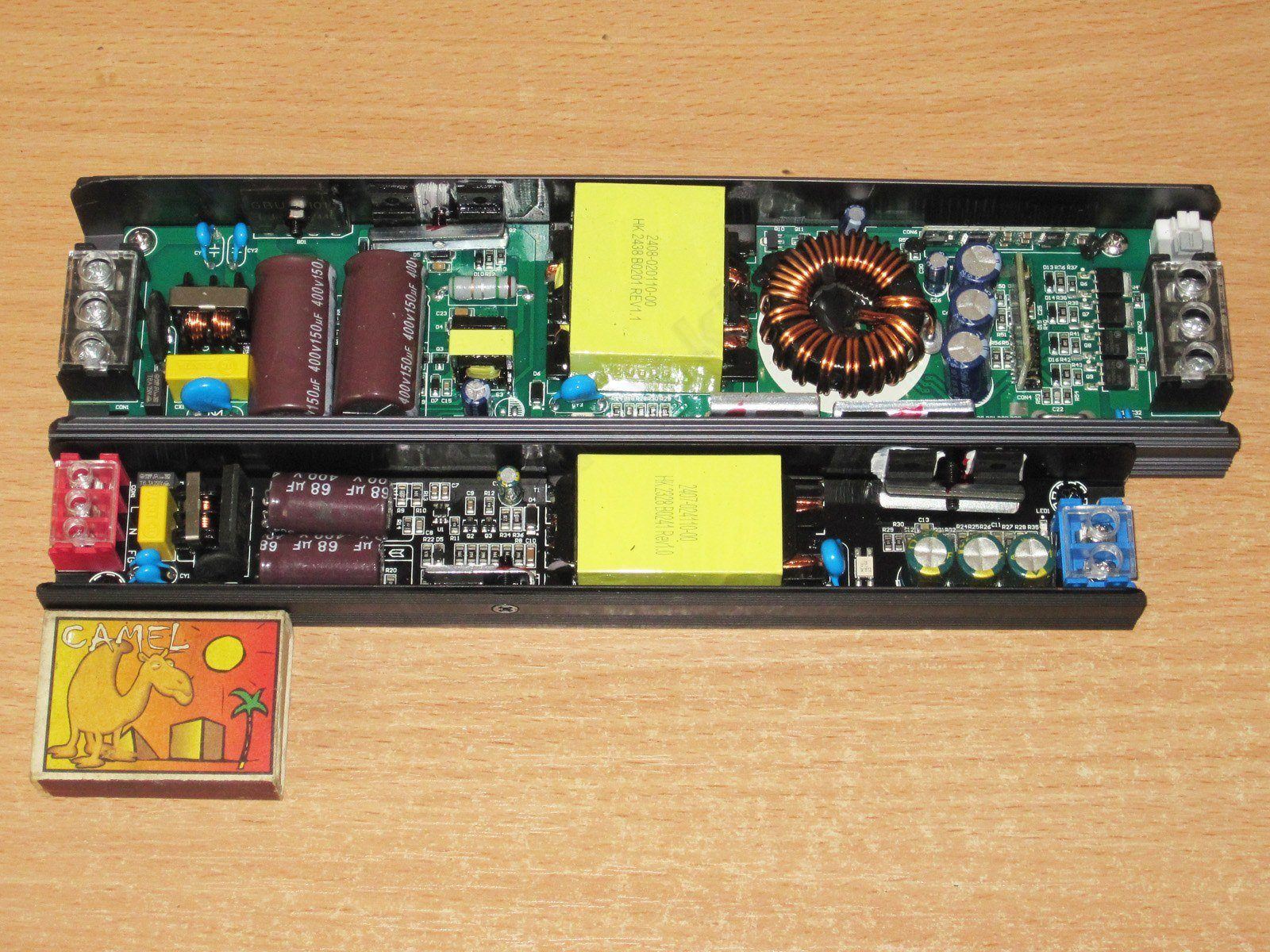
Here are the internals, compared with the previous power supply. You can immediately see that this model has a larger transformer. And since it also uses a different topology, it’s reasonable to expect noticeably more power. It probably won’t actually deliver 400 W, but judging by its size, something around 250–300 W seems more likely.

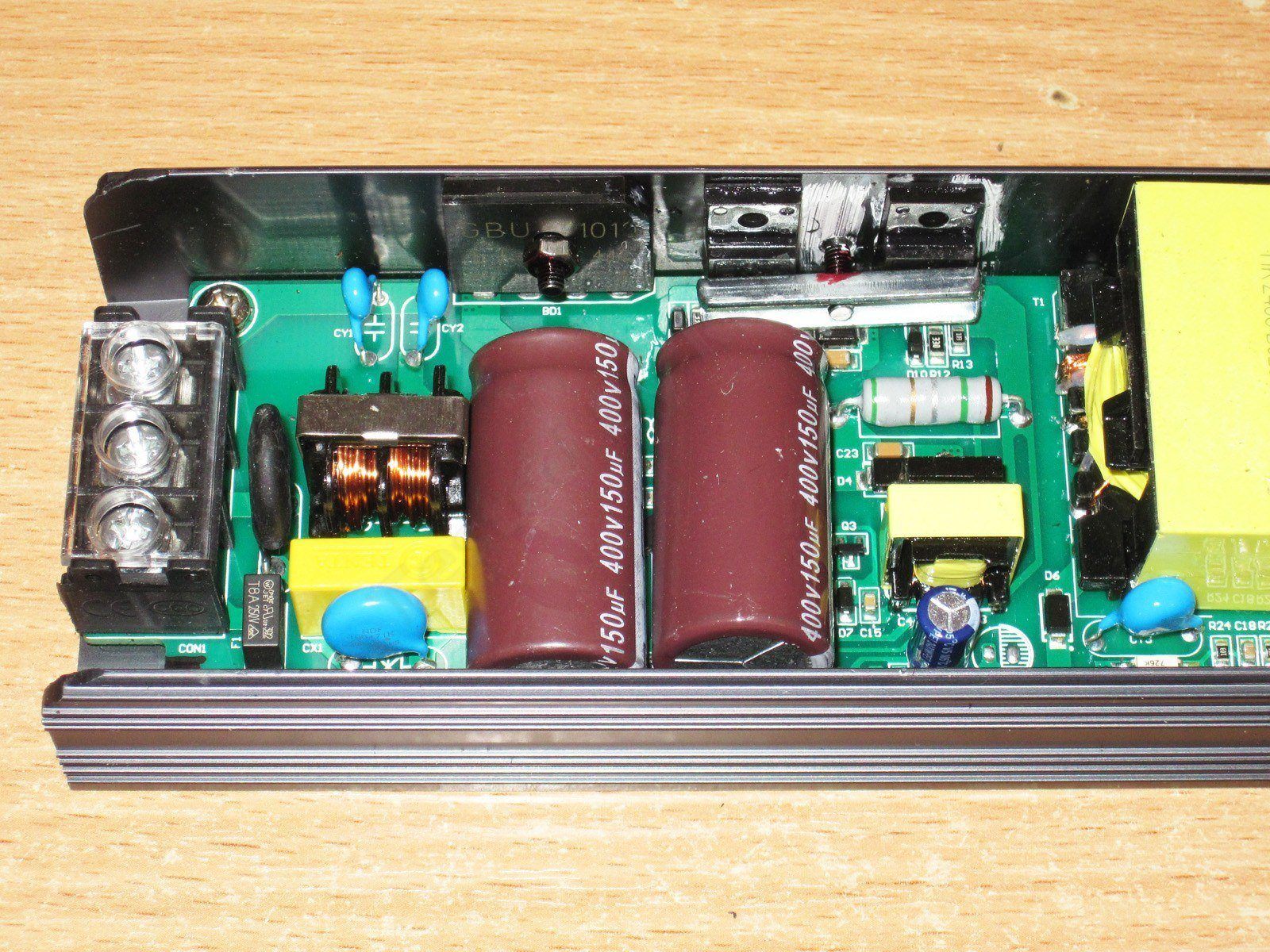
The input section has the now-familiar topology: a half-bridge converter. I seem to be running into this one very often lately.

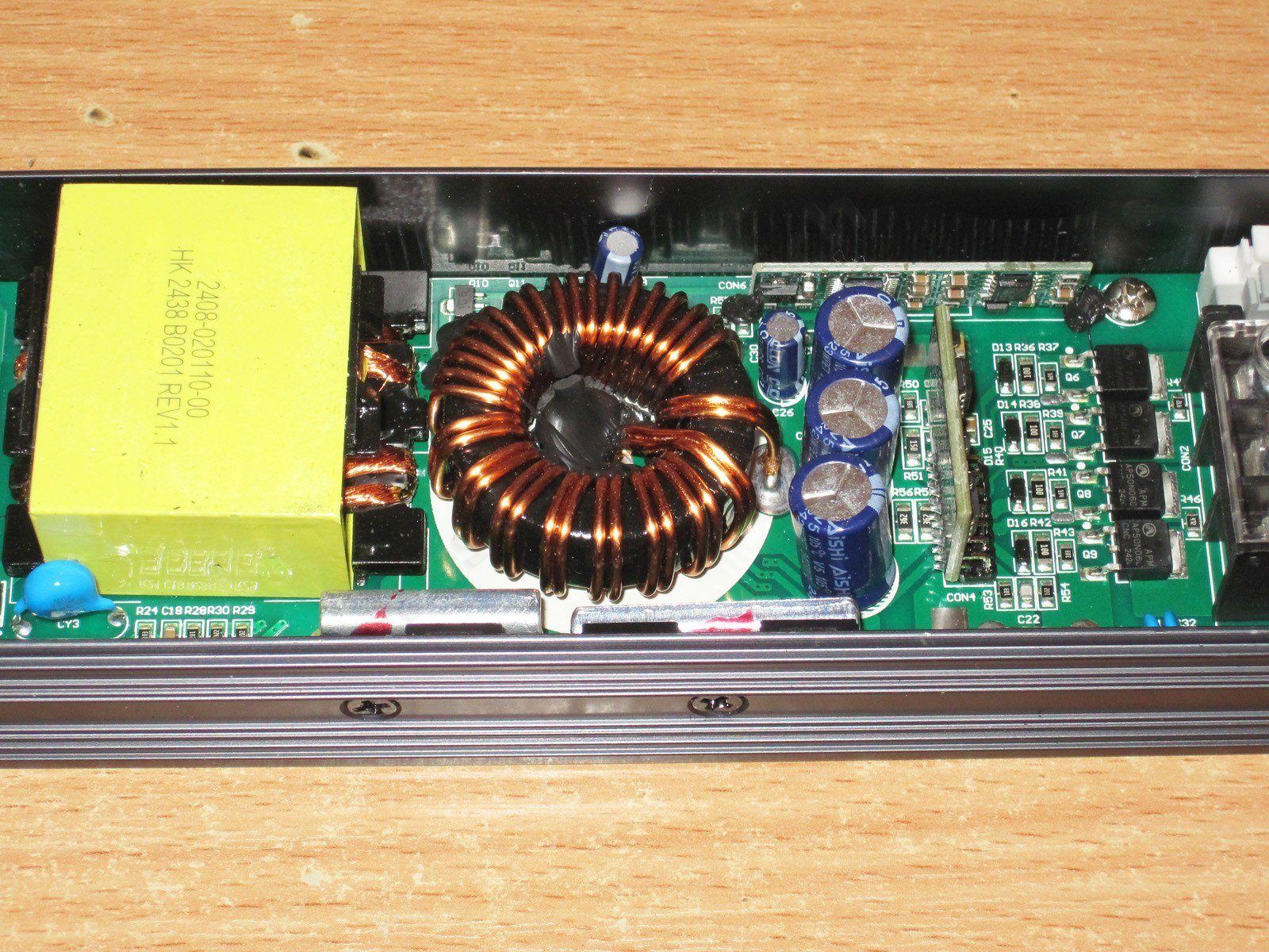
There’s an inductor and capacitors on the output, along with a couple of submodules.

1. The PSU has a full input filter, including a varistor rated for 470 V peak.
2. The filter uses a pair of 150 µF, 400 V capacitors.
3. There’s an output inductor, and the transformer is wound with stranded wire, which is good and proper.
4. The output has three 470 µF, 35 V capacitors. The total capacitance seems a little low to me; 680 µF each would have been a better choice.
5. There’s an extra little board and a bunch of transistors—something I haven’t seen in ordinary power supplies.
6. There are four transistors. We’ll figure out what they’re doing here later.

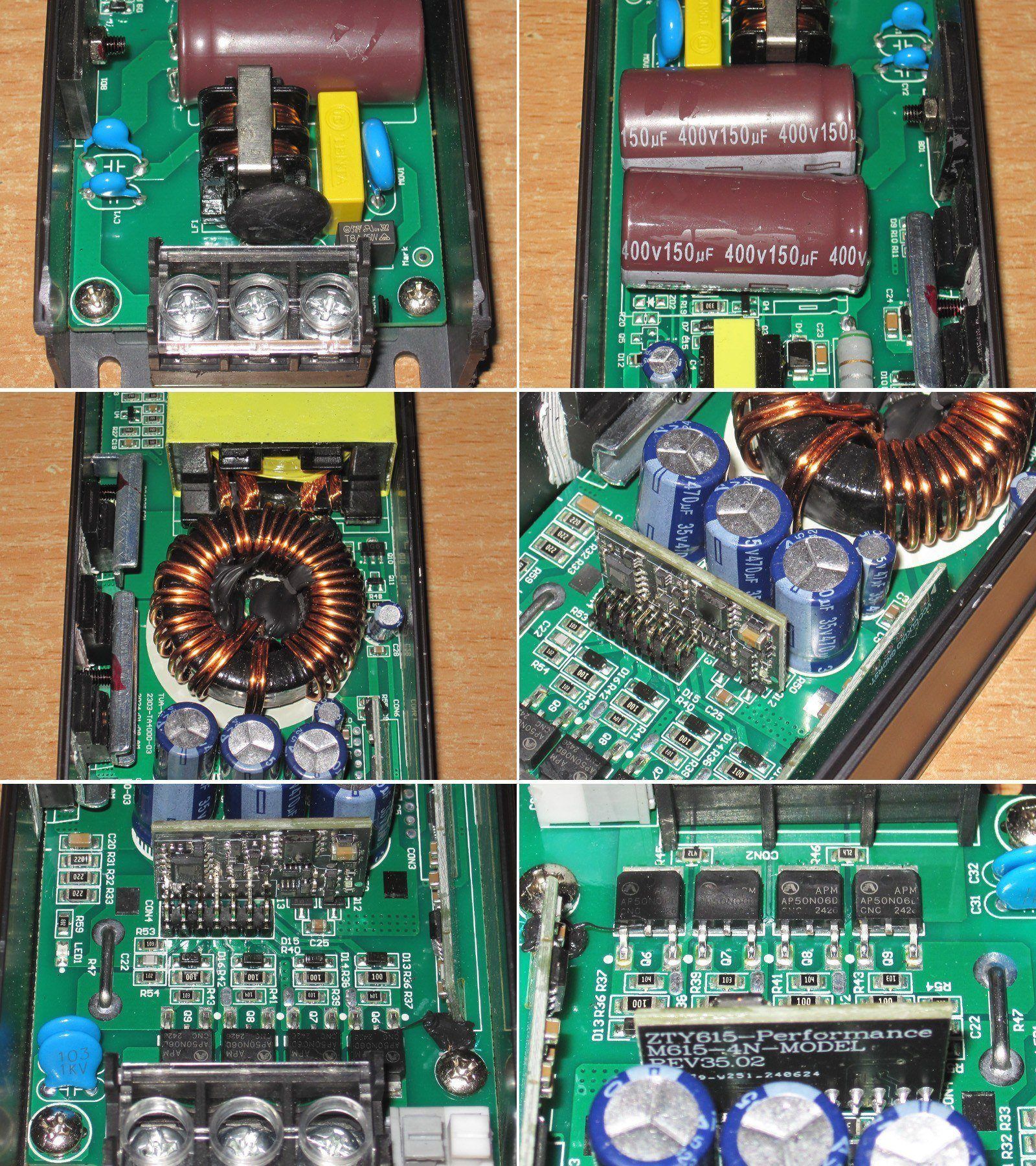
A couple of submodules. The first one apparently controls the additional transistors; the component markings have been rubbed off.
The second board clearly controls the first. It has a microcontroller and an op-amp.
By the way, there’s a current-sense shunt to the left of the first board, so the board monitors current on both the high and low sides.

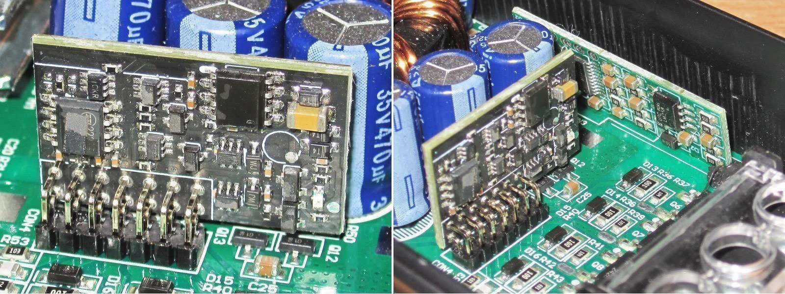
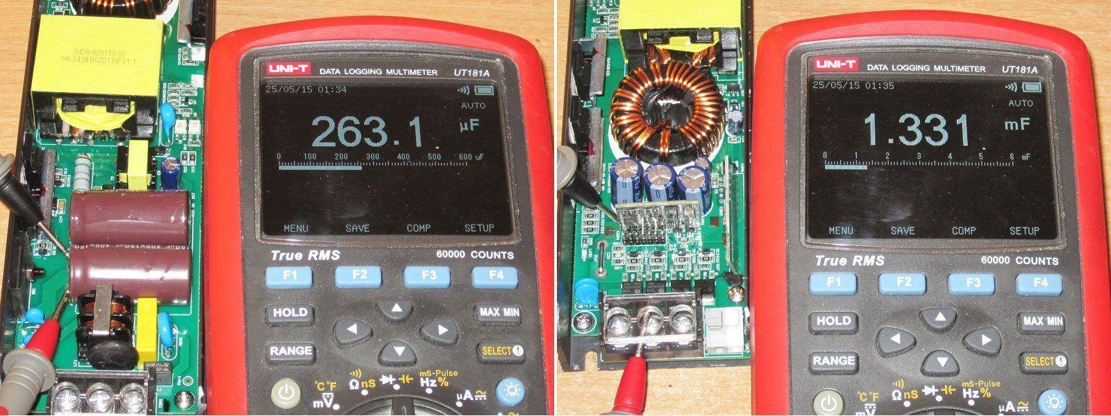
The input capacitors have a total capacitance of about 132 µF, which is perfectly reasonable given the rated 150 µF. The output capacitance is about 1350 µF.

Efficiency and other parameters.
1. The voltage is not adjustable; with no load, it is about 23.8 V.
2. The protection does not trip at a threshold; instead, it reduces the output voltage. This starts when the current exceeds 15 A.
3. At 15 A, the voltage was 23.324 V, about 0.5 V lower than with no load. That's quite a lot.
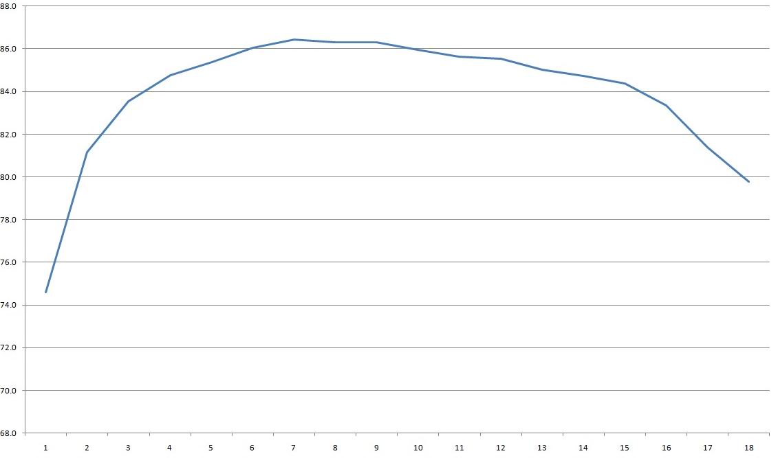
4. Efficiency is about 86%. I wouldn't call that particularly high, especially considering the topology and the fact that this is a 24 V power supply. The 350 W Mean Well rated for the same 24 V is specified at 88% efficiency. The graph shows efficiency from 1 to 18 A in 1 A increments.

Ripple.
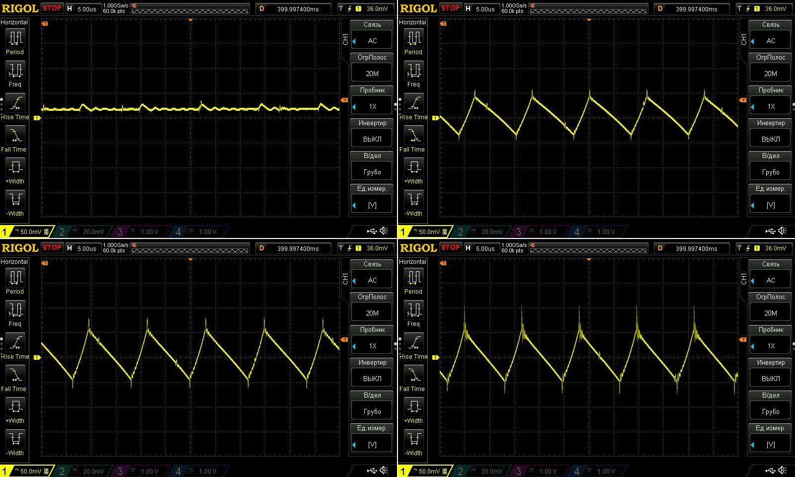
As is usually the case with this topology, ripple is quite low, especially considering that this is a 24 V power supply: about 100 mV at 14 A.
Below are the results with no load and at 5, 10, and 14 A.

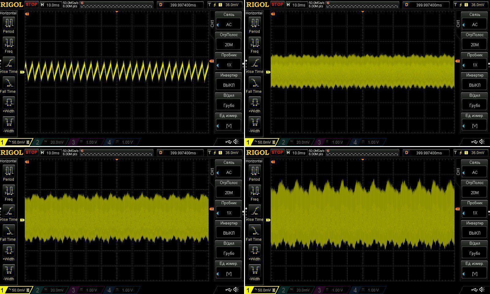
The low-frequency ripple is also pretty good overall. Only at maximum current do 100 Hz spikes start to appear, but they're small enough to ignore.

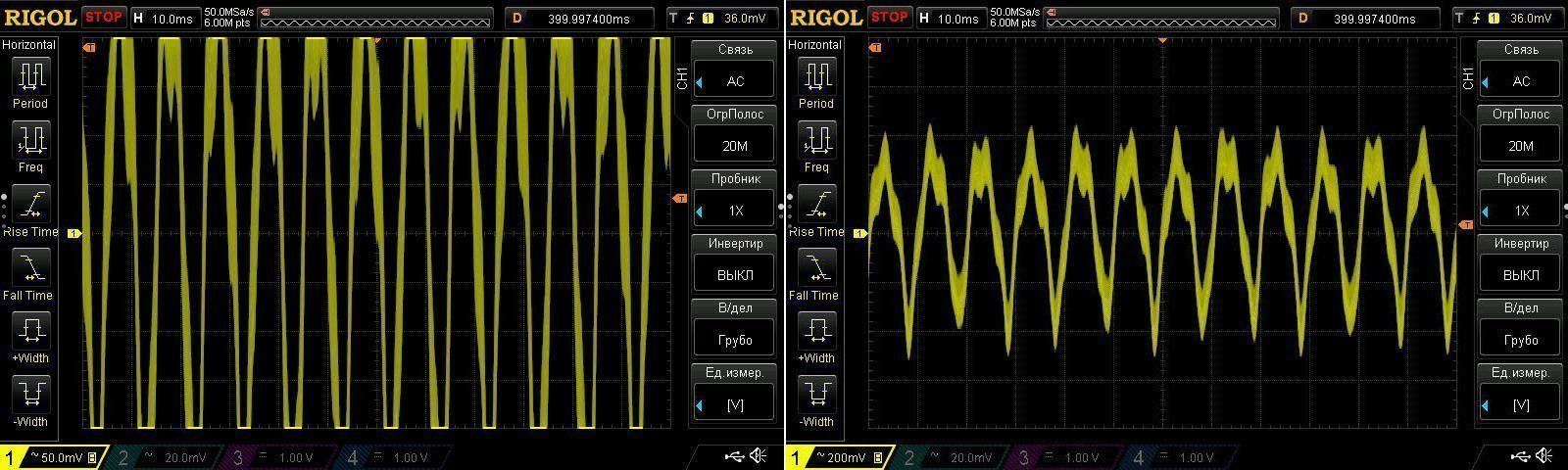
Everything looked good until I raised the load current to 15 A while measuring low-frequency ripple. That's when things got weird.
On the left is the waveform at the same 50 mV per division as above, for comparison; on the right, it's rescaled for measurement: almost 1 V.
It looks like this is how the power supply's power limit works, so 14 A is its maximum.

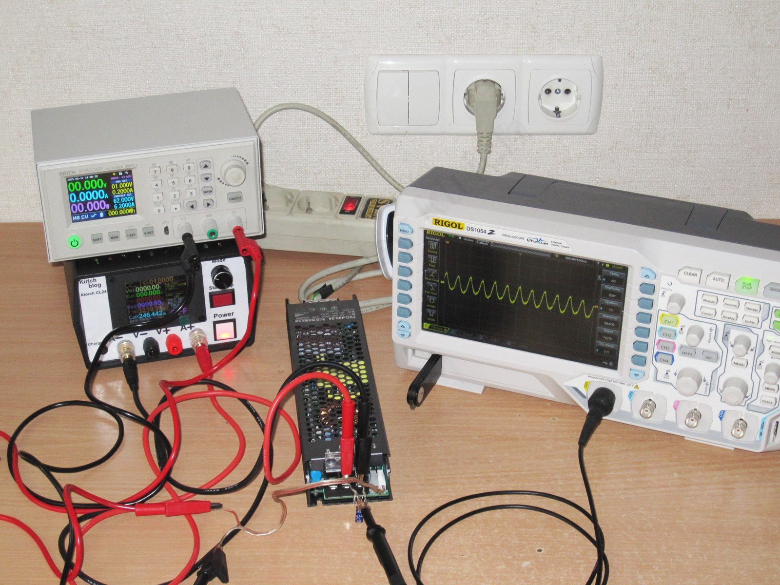
For the additional tests, I had to use an adjustable power supply to provide a 0–10 V control signal.
I also noticed that, due to the design of the power supply under review, some interference from the adjustable power supply gets onto the output when it's switched off, although it's not much.

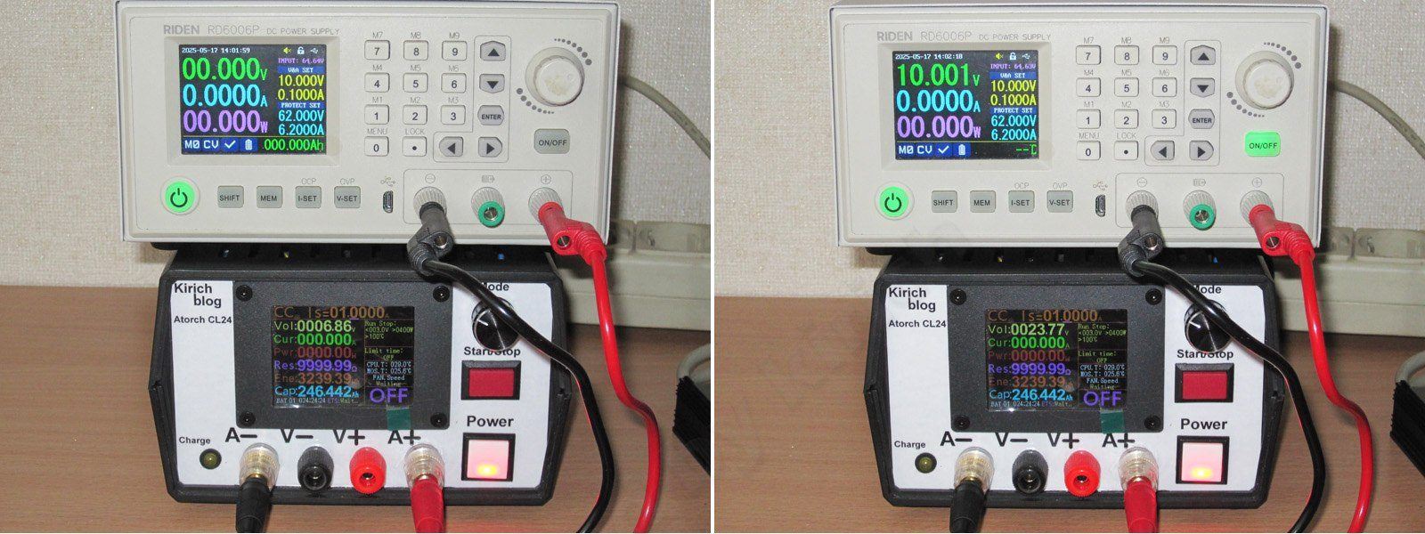
With zero voltage at the output, there was still about 6 V, although logically it should have been zero. Raising the voltage even slightly immediately brought it to about 23 V. At 10 V, the output is fully on and we get the full voltage.

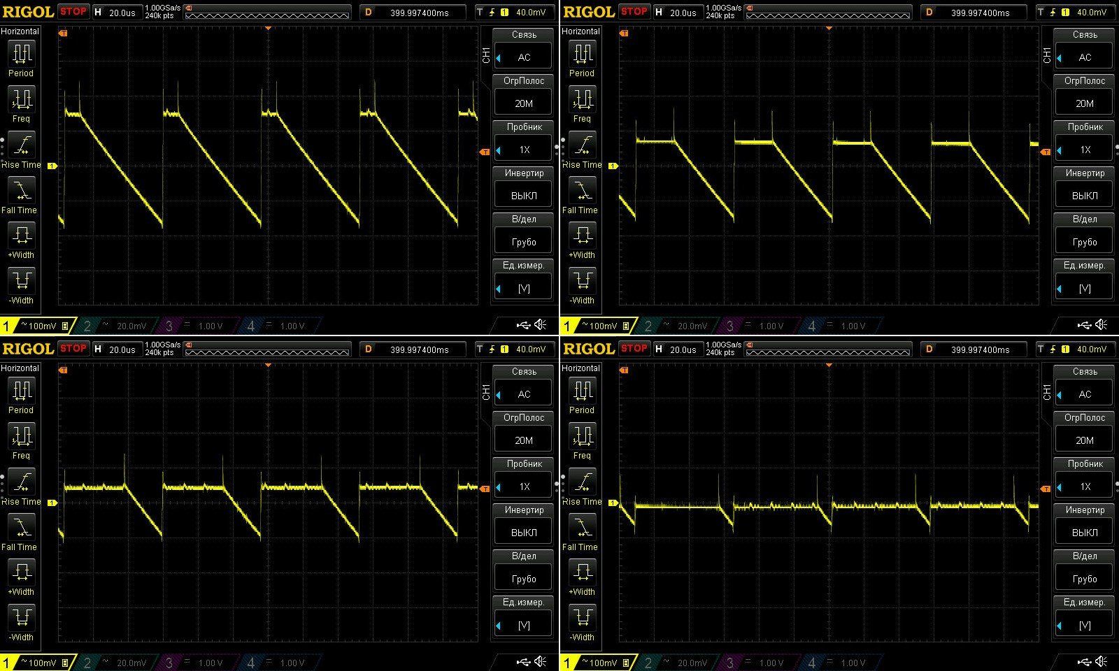
In fact, the voltage isn't regulated here; instead, the PWM duty cycle changes. The PWM frequency is about 18 kHz. I think they chose this frequency so the load wouldn't make an audible buzzing sound.
Waveforms with a 1 µF capacitor at the output (I forgot to remove it) and control voltages of 2, 4, 6, and 8 V. Under load, the waveform will actually look something like a square wave, but that's not important here.

Here I momentarily forgot that there was a capacitor at the output and tried loading the power supply. First I noticed a faint, suspicious smell, then a little smoke.
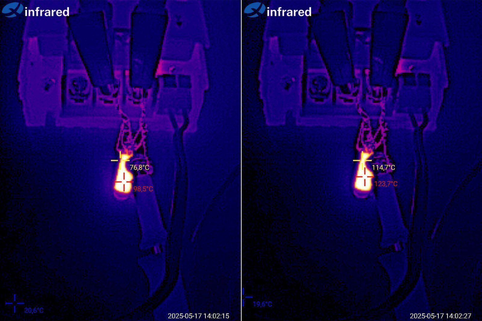
I switched it off and started looking for what was getting hot. It turned out to be the capacitor. I turned the load back on and checked it with a thermal camera.
The capacitor heats up very quickly: in just 13 seconds, it went from 98 to 123 degrees, and the temperature kept rising.
Consider this a warning. If the load connected to this power supply has capacitors at its input—for example, an electronic device—do not use the control signal under any circumstances. You can control something simple, such as an LED strip or an incandescent bulb. In theory, you could connect a brushed motor, but I wouldn't do that.
By the way, I almost forgot: when power is applied, the output voltage doesn't appear immediately; it ramps up gradually over a few seconds. Neat :)

Load tests.
Cold and unloaded, the voltage was 23.832 V.

1. At 4 A, the voltage dropped to 23.739 V while the unit was cold.
2. With the unit warm and at 8 A, it dropped further to 23.605 V.
3. With the unit warmed up and at 12 A, the voltage dropped to 23.408 V.
4. Then, with the unit already hot, I reduced the load current from 12 to 10 A, and the voltage was 23.4 V.
5. After half an hour, with the unit hot and at 10 A, the voltage had risen slightly to 23.428 V.
6. With the unit hot and no load, the voltage was 23.758 V.
In short, the voltage does depend on temperature, but within acceptable limits. Its dependence on current, however, is quite significant. Not that it’s critical, but that’s how it is.

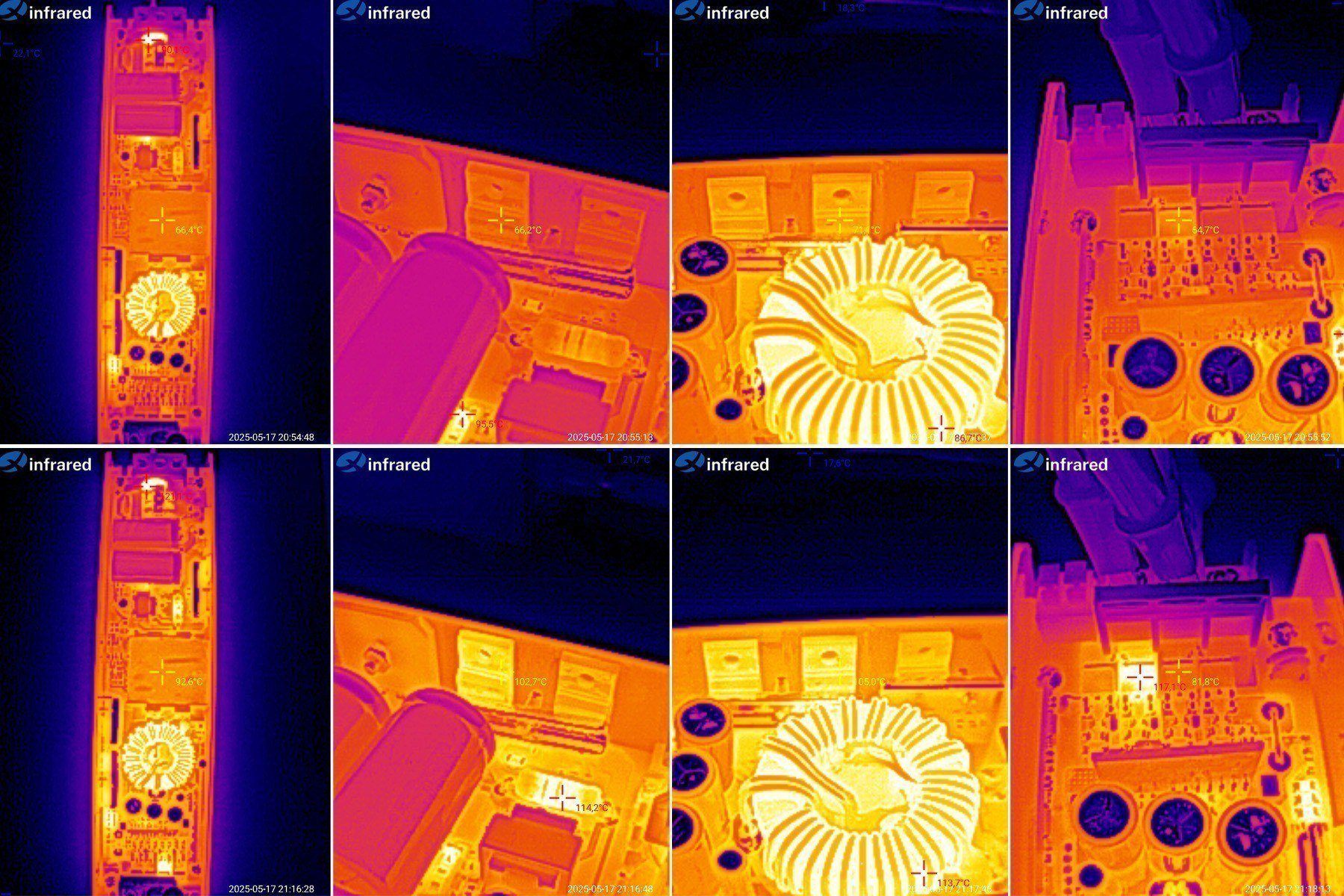
Now let’s look at the component temperatures. I won’t include the results at 4 A; I’ll show what I got at 8 and 12 A.
8 A — transformer 66 degrees, transistors 66 degrees, diode assemblies 71 degrees, inductor 87 degrees, one of the additional transistors 65 degrees.
12 A — transformer 93 degrees, transistors 103 degrees, diode assemblies 106 degrees, inductor 114 degrees, additional transistor 117 degrees.
Temperature-wise, my biggest concerns are the output inductor and the additional transistor. I think that transistor is what knocked the power supply’s efficiency down a bit.

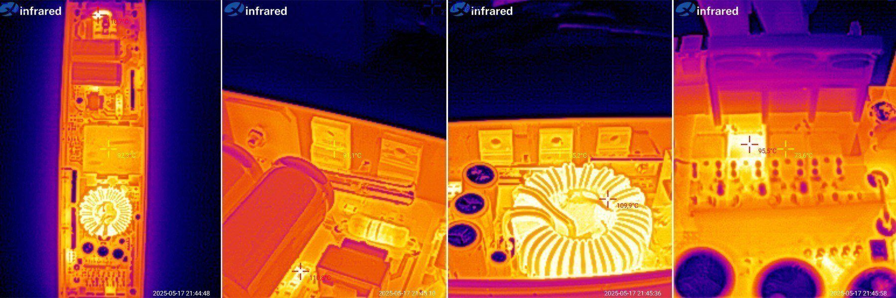
Next, as an experiment, I reduced the load current to 10 A, so the power was around 240 W, and ran it like that for another half hour or so.
The results: transformer 92.3 degrees, transistors 91 degrees, diodes 95 degrees, inductor 110 degrees, additional transistor 96 degrees.
So 240 W is the maximum continuous power this power supply can deliver at room temperature.

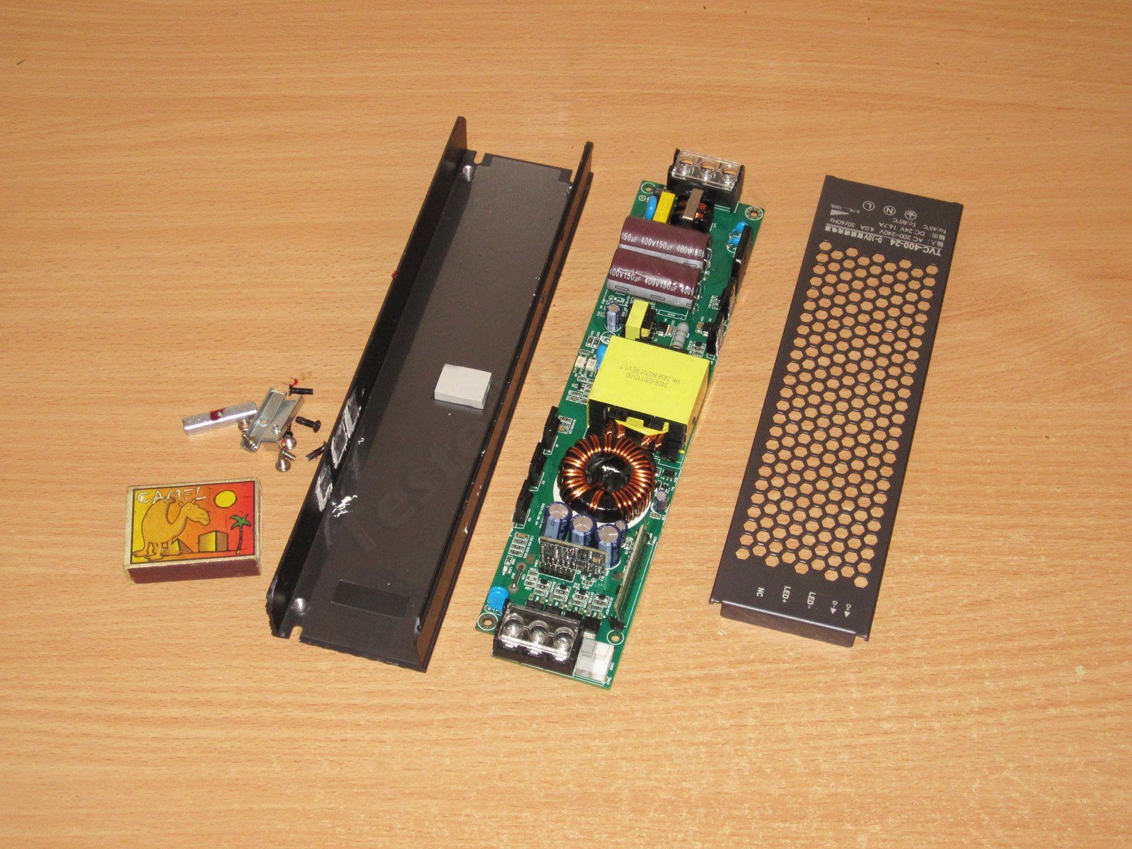
After the heat test, I decided to take a closer look, so I removed the board from the case. There’s a thermal pad under the transformer, by the way, but I’d add another one.

It looks neat. You can also see another thermal pad at the bottom right; it carries heat away from the additional transistors.

The board is a little dirty, but not too bad. There are no slots, but the clearances are sufficient, so I have no safety concerns either.

High-voltage section with the case removed.

1. The 18N50 transistors are rated for 18 A and 500 V, which is perfectly adequate.
2. The power supply has not only the main feedback loop, but also an overvoltage protection circuit on the output.
3. The output diode assemblies are rated for 20 A and 200 V. As a reminder, they aren’t connected in parallel here; they’re split into two groups. Since one “half” runs hotter, there are probably two assemblies in one leg and one in the other, which makes sense.
4. An additional voltage regulator supplies power to the auxiliary boards.

The PWM controller and its surrounding components.

If you didn’t notice, the thermal image of the transistors clearly showed one running hotter than the other. Here’s why: thermal paste covers only half the case on one transistor. That’s why I run the thermal test first and only then take the power supply apart.

About the additional transistors. Remember I mentioned that the terminal block has an NC contact? It turns out the power supply actually has two channels, but the second one is disabled in software.
Each channel is handled by two transistors connected in a half-bridge configuration. The positive output is connected directly, while the negative side is switched by one of the transistors. The second transistor apparently shorts the output when there’s no control signal. I think this trick is meant to stop the LED strip from glowing due to interference.
At first I thought all four transistors were connected in parallel, but it turns out the circuit is much more complicated than that.

Conclusions.
I usually form my conclusions while writing a review: I sort through all the information I’ve gathered and then draw conclusions based on it. Here, though, I’d already formed my opinions and conclusions during testing, because I actually liked these power supplies, even if not everything about them.
The first power supply is a perfectly honest unit for 100 W continuous and 120 W short-term. The build quality is quite good; they clearly cut corners on some components, but within reason.
For the second power supply, I’d say its honest continuous power is around 200–240 W, with a maximum of 280 W. The build quality is also good, and the components are clearly better.
Overall, both power supplies left a very good impression. They’re neatly assembled, the board is coated with protective varnish, and they’re even kind of attractive. There are a few minor flaws, but the main issue is the stated power and specifications. What kind of 400 W are we talking about? The first unit can really deliver only 25–30% of its rated power; the second does better, at around 60%. But honestly, claiming 400 W for a unit that can’t deliver that much even “in a sprint” is ridiculous. At least the protection is set up reasonably well, so it’ll be hard to overload them.
A note about protection. As you’ve seen, temperature is the main problem. And what’s striking is that the vast majority of these power supplies have no thermal protection. Even more striking, in the vast majority of cases the PWM controller can monitor temperature; they just don’t install a thermistor, replacing it with a “dummy” component. How does that make any sense?
Now, about power. I specify continuous power at room temperature. If you install the power supply in an electrical panel, you need to derate it, because the air temperature there will clearly be higher. And here we’re back to the question of whether it has thermal protection. In short, there’s still room for improvement—and for giving the power supply manufacturers a nudge.
That’s all for today. I hope this was useful, and thanks again to Vitaly for providing the power supplies for testing.
A reminder: to keep up with new posts on the blog, I recommend following me on Instagram. I’ll post notifications about every new topic there, and might also write about something interesting now and then - link to account
You can also subscribe to updates and new articles on the Telegram channel - https://t.me/KirichBlog
Even at first glance, you notice the packaging. It’s not the usual plain white or gray box, but one with full-color printing. The Chinese are certainly good at making things look impressive, but to be fair, it really works: if a store shelf has two boxes, one plain gray and one attractive, the customer is much more likely to choose the latter.

I’ll start with the smaller one, which is rated at 12 V, 33 A, and 400 W on the case.
It looks nice, but somehow... clearly not like a 400 W unit. The case measures 230 × 34 × 24 mm.
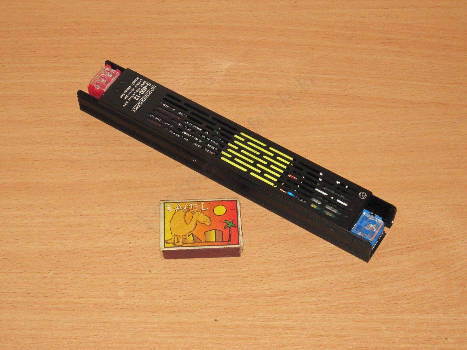
There are terminal blocks with neat little covers at both ends. I’d give them five stars if not for one detail: there’s a screw to the right of the terminal, and the board is well supported there, but on the left there’s neither a screw nor a support. When you tighten the screw, the board bends noticeably.
Getting inside is very easy; you just need to remove the top cover.
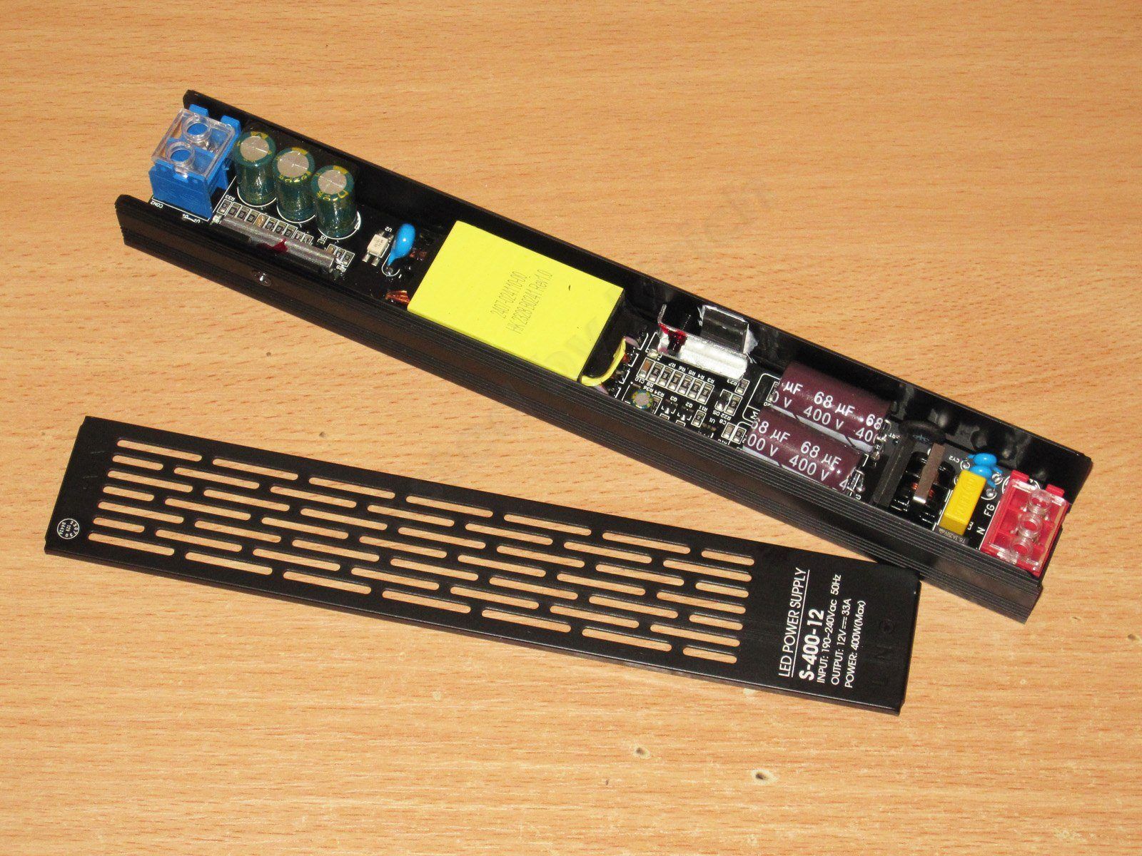
The input has a filter, a fuse, and a thermistor. The input capacitors are rated at 68 µF, 400 V, two of them. That’s clearly too little for 400 W. It’s also obvious that this power supply uses a flyback topology, which means there’s no way it can deliver 400 W with a transformer like this—not even 200 W. Maybe 150 W.
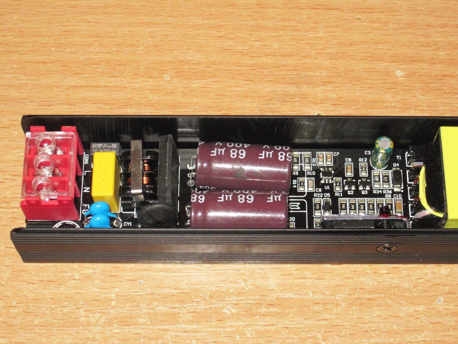
On the output side, there are a pair of diode assemblies, three capacitors, and a handful of other components.
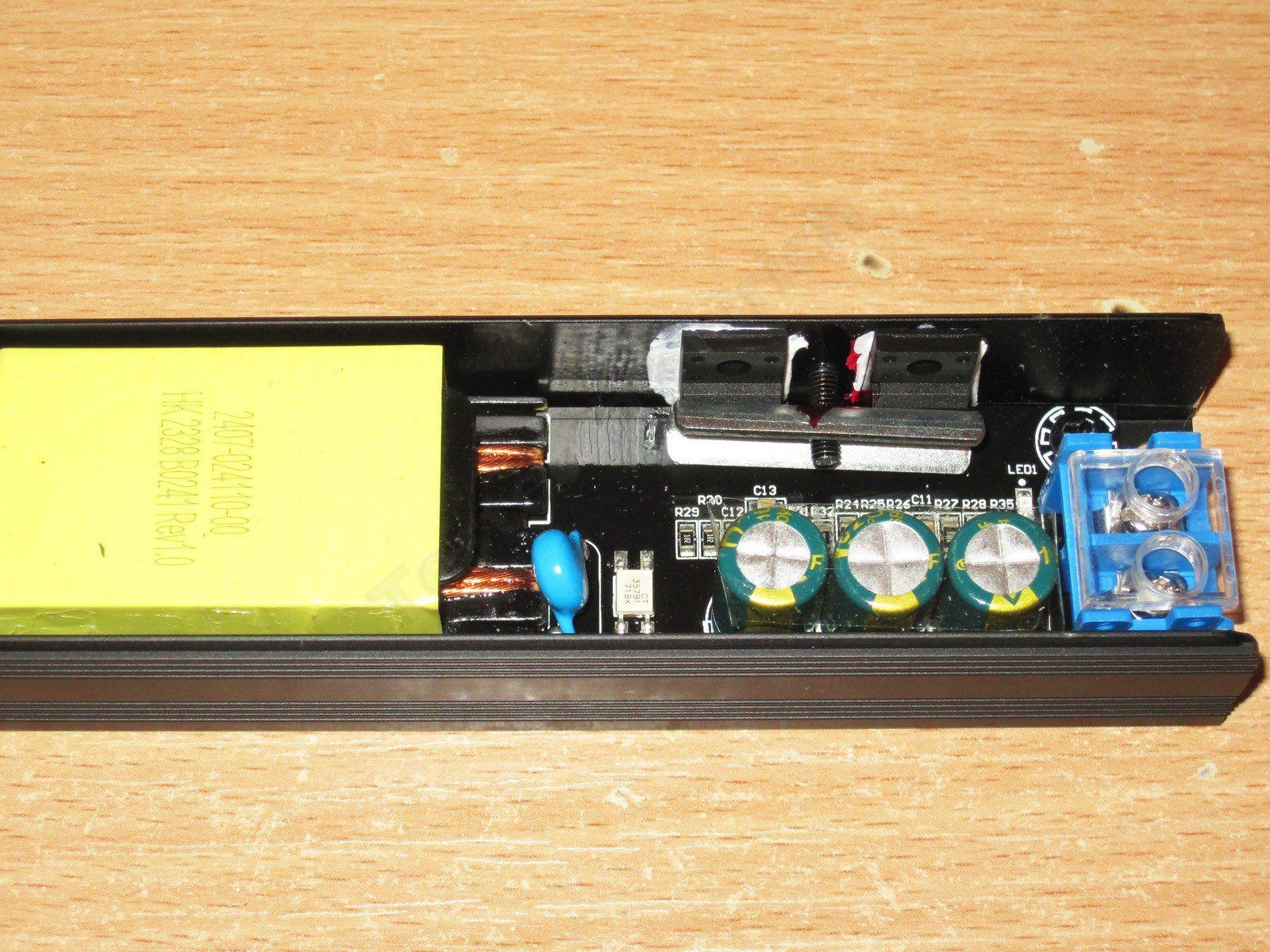
The input capacitors add up to 2 × 68 = 136 µF, but the actual measured capacitance is 87 µF—not much. By the way, this power supply is rated for an input voltage starting at 190 V. I’m almost certain it will also work from 115 V, with some reduction in power.
The output side is fine; the installed 3000 µF is all there.
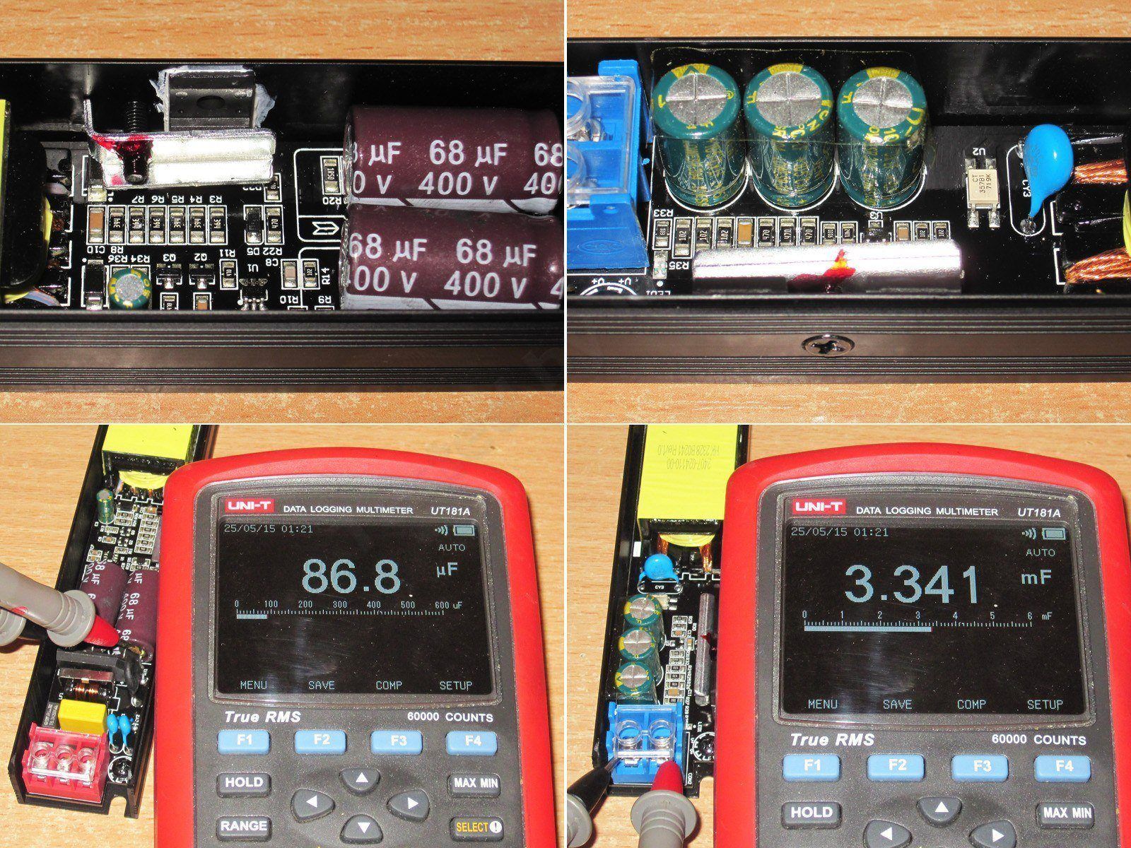
I took it apart further after the tests, to make sure the testing was done correctly, but I’ll show that part now.
There are a couple of thermal pads under the board: one near the high-voltage transistor, the other near the transformer’s output pins. I don’t understand why they didn’t put a pad under the transformer.
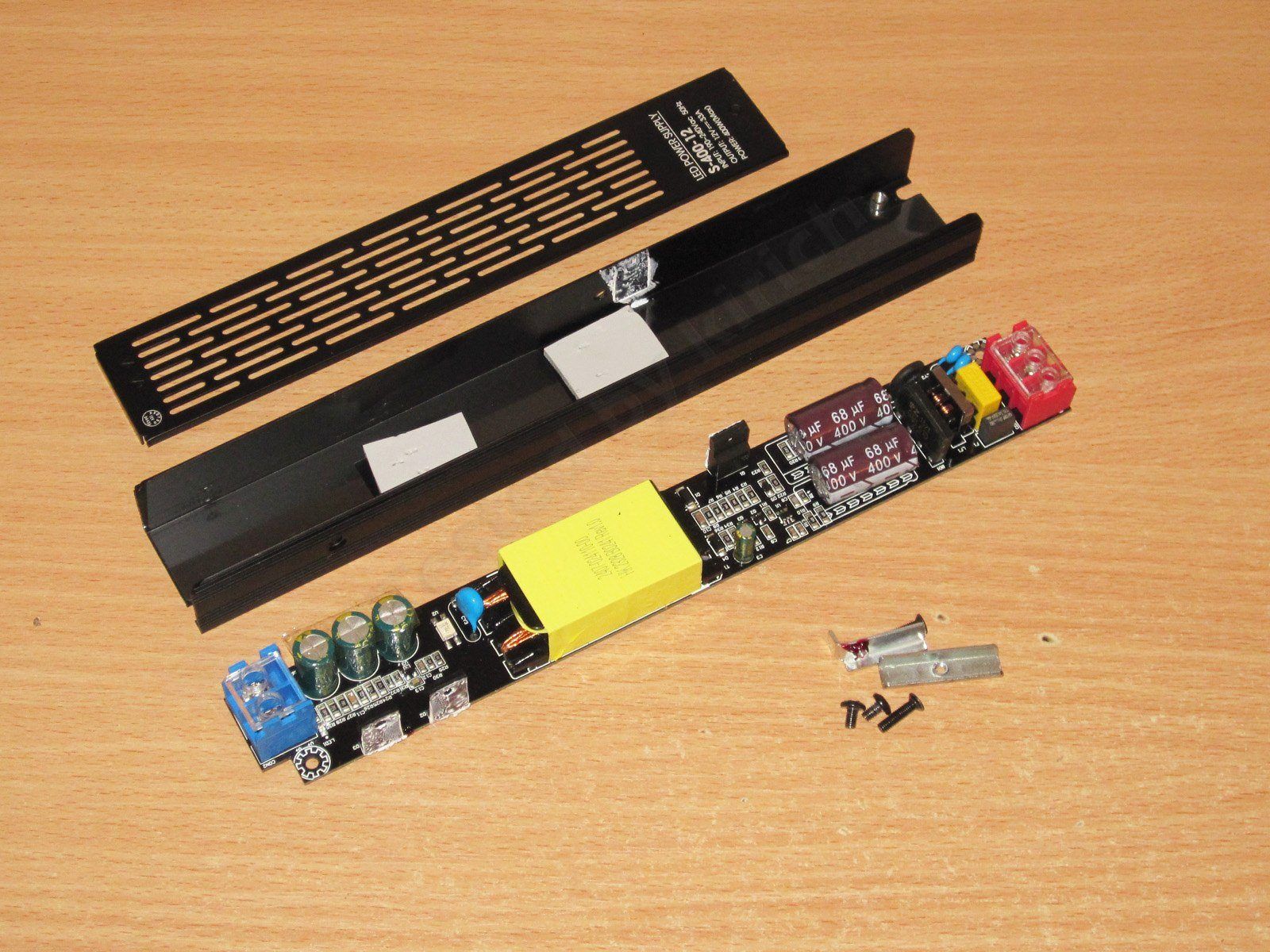
The PWM controller section is neatly soldered, and the board is coated with varnish. Definitely a win here.
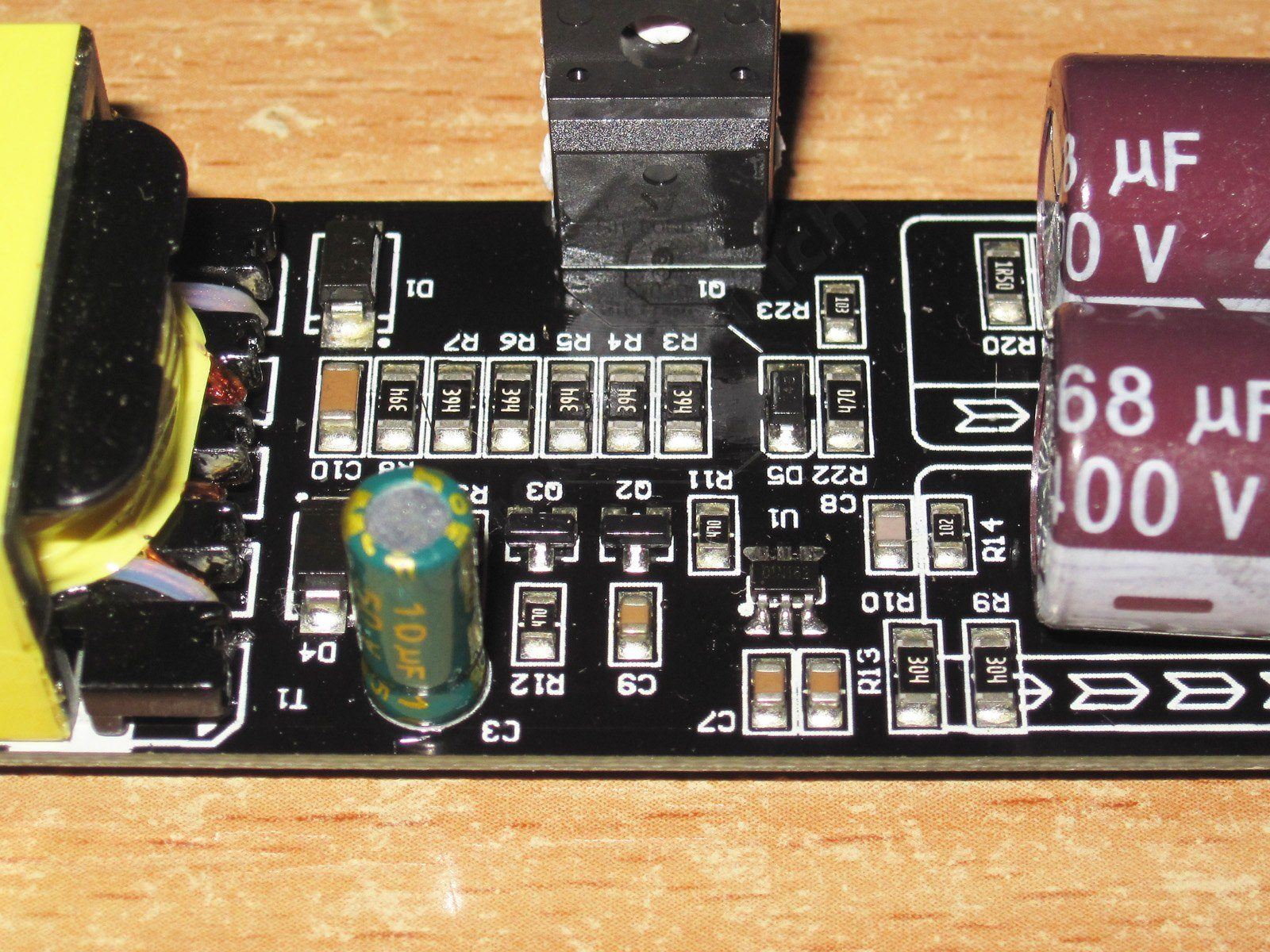
1. PWM controller. To the left, you can see a pair of emitter-follower transistors driving the high-voltage transistor—a good solution.
2. 10N60 transistor, rated at 10 A and 600 V according to the markings.
3. The transformer is actually not that small, by the way. I especially like its long, narrow design; in theory, it should dissipate heat well.
4. The interwinding capacitor is the right type. The transformer is wound with a bundle of many thin wires, which is also good.
5. The output diode assemblies are rated at 30 A, 100 V, and are connected in parallel, giving a current capacity of up to 60 A. No complaints here either, given the actual power rating.
6. As expected, the output capacitors are rated at 16 V. Too bad.
The underside is just as neat. There are no components here, but the board is clean. There’s a “window” under the transformer that’s practically begging for a piece of thermal pad.
There’s a gap around the interwinding capacitor, so no issues there. I also didn’t spot any narrow clearances around the optocoupler, although it’s quite difficult to make out anything on the black board.
And of course, the tests: power, ripple, and temperature rise. Judging by the markings, this really calls for a higher-current load, but the reality turned out to be much simpler.
While measuring efficiency, I found a few other things:
1. No-load voltage: 11.91 V
2. Maximum continuous current is about 10 A; the protection trips at 11 A.
3. At 10 A, the voltage drops to 11.885 V, which is actually pretty good.
4. Efficiency is around 84%, an average result.
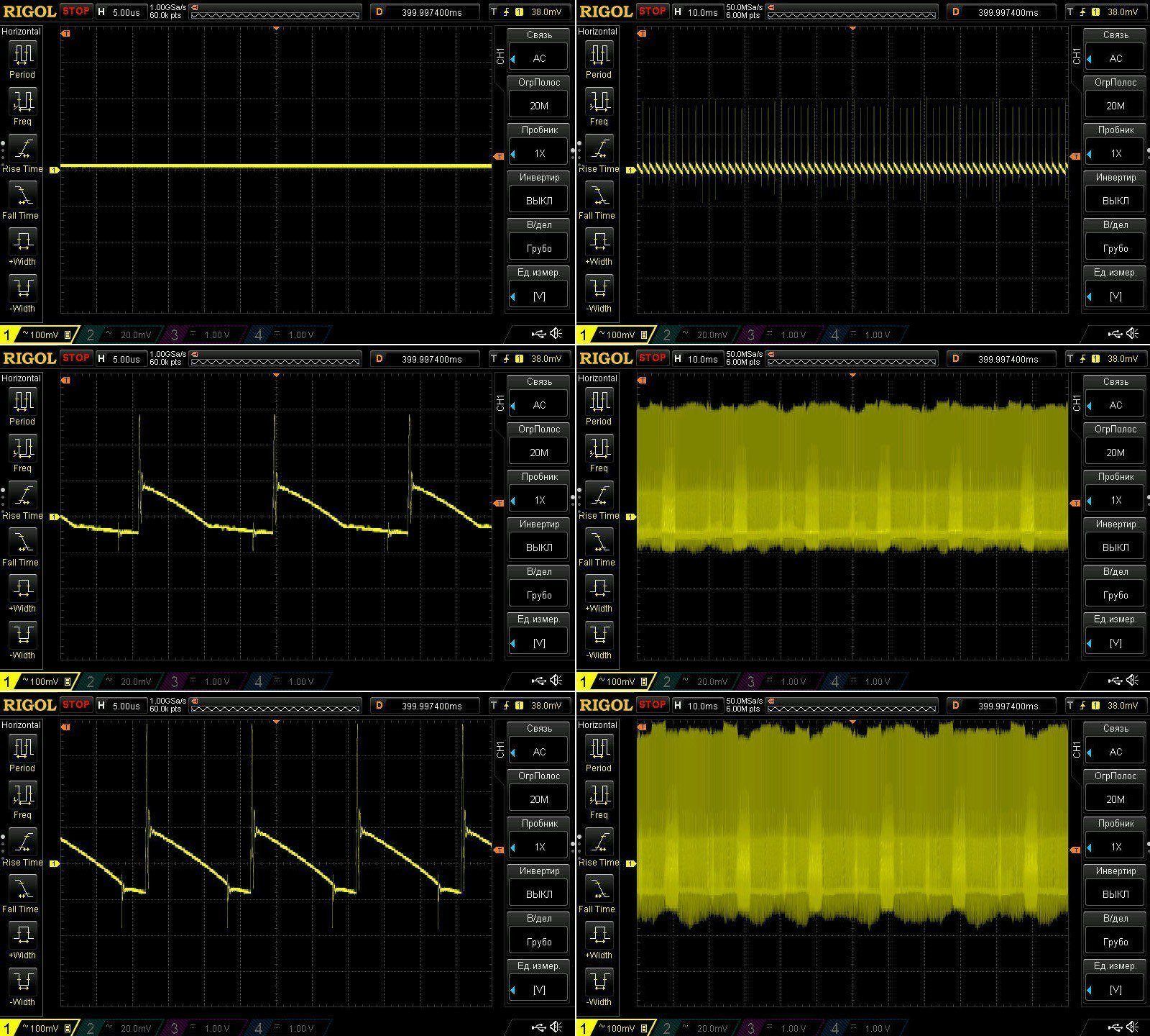
Ripple. A flyback power supply with no output filter, so the ripple is usually relatively high.
But I have to say, for a flyback PSU without a filter, it’s really not that bad:
1, 2. No load; ripple is visible only at low frequencies, which is normal.
3, 4. 5 A load: the main high-frequency ripple is around 120 mV, but there are some pretty large “spikes.” Low-frequency ripple is fine.
5, 6. 10 A load: around 180 mV at high frequencies. It would be great if not for the “spikes”—an output inductor is clearly called for. Low-frequency ripple is basically fine.
I’ve written about these “spikes” before. They’re not that bad for the load, since they’ll simply drop across the wires. What makes them undesirable is the noise they radiate and the extra stress they put on the PSU’s output capacitors. Unfortunately, this is a characteristic of single-ended flyback power supplies, to a greater or lesser degree in all of them.
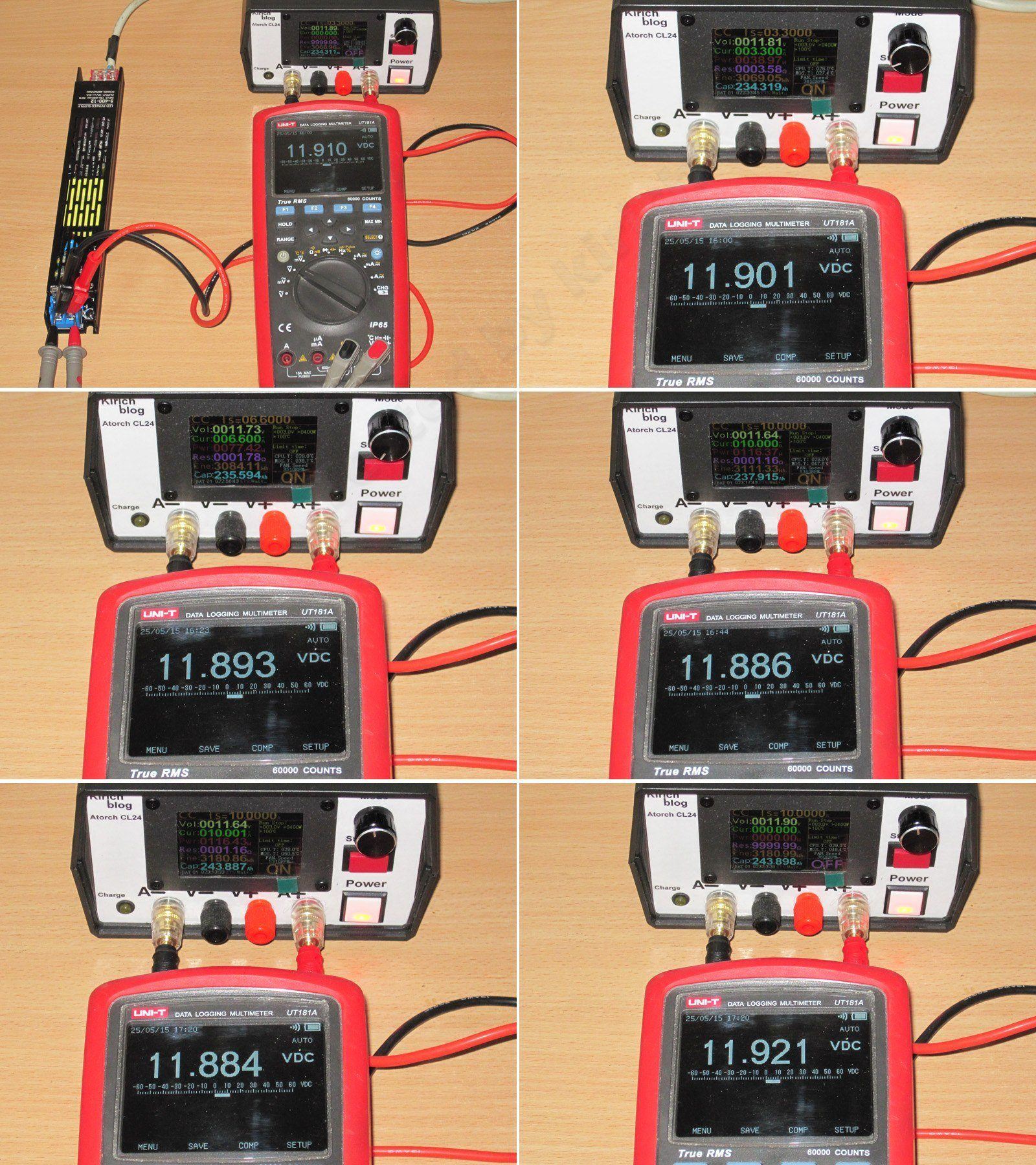
Thermal test.
1. Cold PSU, no load
2. Cold PSU at 3.3 A
3. Warm PSU at 6.6 A
4. Warm PSU at 10 A
5. Hot PSU at 10 A
6. Hot PSU, no load.
The results are very, very good. The PSU’s output voltage is almost unaffected by either the load or the temperature. Kudos.
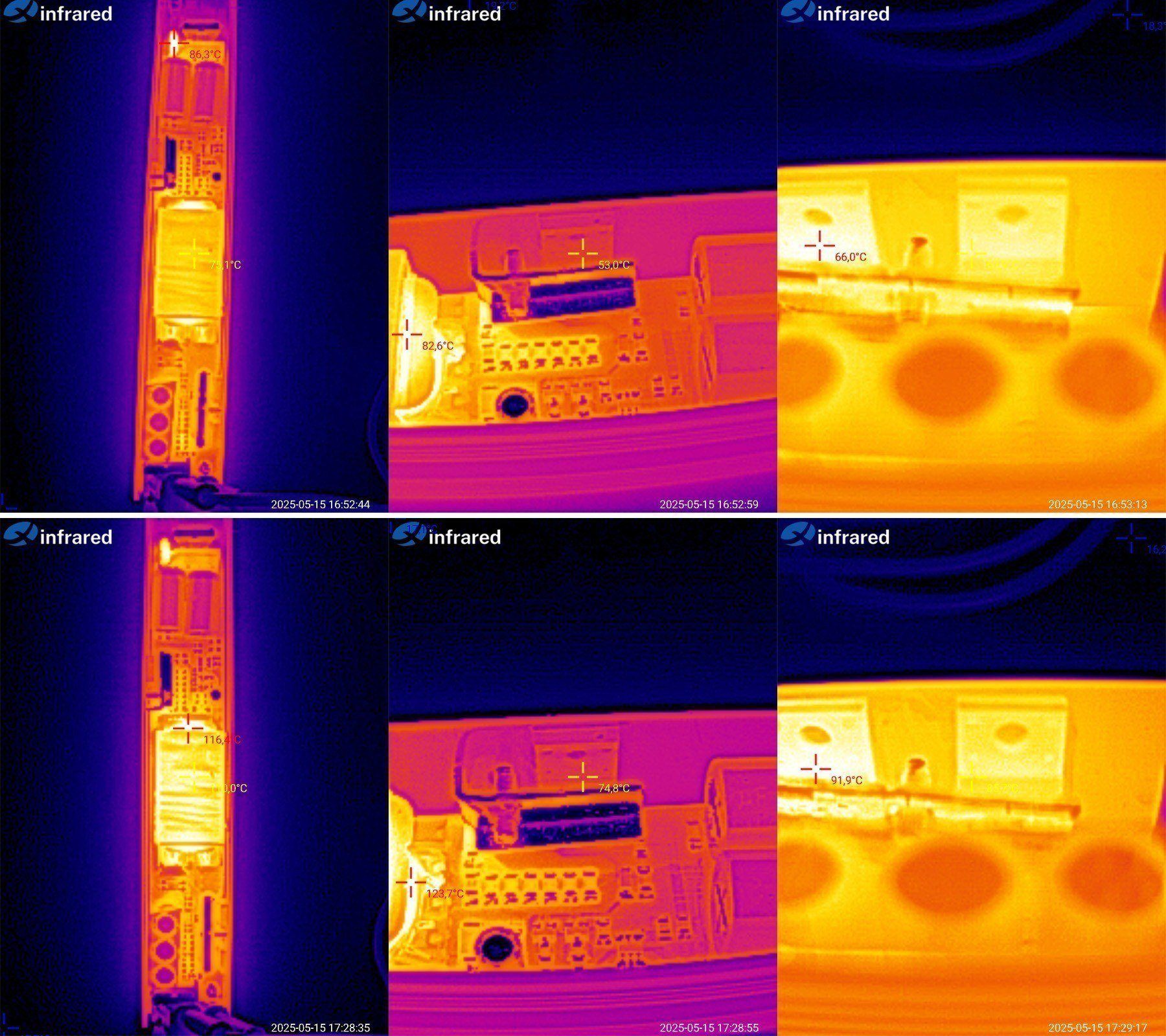
The thermal test was run at 3.3, 6.6 and 10 A, for about 20–25 minutes at each step. There’s no point showing the results at 3.3 A, so I’ll show the readings at 6.6 and 10 A.
1. At 6.6 A: transformer at 75°C, transistor at 53°C, output diodes at 66°C. Quite good.
2. At 10 A: transformer at 110°C, transistor at 75°C, diode assemblies at 92°C.
Basically, my only concern is the transformer temperature. 110°C is very high, so in my opinion the PSU’s long-term maximum output is around 100 W.
The second model is more interesting. Its rated specs are 24 V, 16.7 A, 400 W.
The packaging is even fancier here; there’s even a special tray for the power supply itself.
What makes it more interesting is that it lets you control the power delivered to the load. It supports three control methods; this review covers the simplest one, using a 0–10 V control signal.
It’s clearly larger at 250 × 60 × 29 mm, and feels noticeably heavier in the hand.
Here it is next to the previous model. The funny thing is that both have the same rated power: 400 W :)
The terminal blocks are the familiar type, with protective covers. There are three mains input terminals on one side, and the load and control signal connections on the other.
The power terminal block has three contacts, one of which is marked NC. We’ll come back to that.
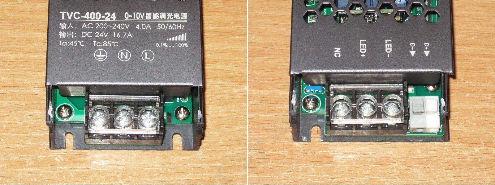
This particular unit seems to have had a rough trip somewhere along the way: the case is slightly bent. Fortunately, it’s not bent on the side with the power components, so it’s not a major issue.
Here are the internals, compared with the previous power supply. You can immediately see that this model has a larger transformer. And since it also uses a different topology, it’s reasonable to expect noticeably more power. It probably won’t actually deliver 400 W, but judging by its size, something around 250–300 W seems more likely.
The input section has the now-familiar topology: a half-bridge converter. I seem to be running into this one very often lately.
There’s an inductor and capacitors on the output, along with a couple of submodules.
1. The PSU has a full input filter, including a varistor rated for 470 V peak.
2. The filter uses a pair of 150 µF, 400 V capacitors.
3. There’s an output inductor, and the transformer is wound with stranded wire, which is good and proper.
4. The output has three 470 µF, 35 V capacitors. The total capacitance seems a little low to me; 680 µF each would have been a better choice.
5. There’s an extra little board and a bunch of transistors—something I haven’t seen in ordinary power supplies.
6. There are four transistors. We’ll figure out what they’re doing here later.
A couple of submodules. The first one apparently controls the additional transistors; the component markings have been rubbed off.
The second board clearly controls the first. It has a microcontroller and an op-amp.
By the way, there’s a current-sense shunt to the left of the first board, so the board monitors current on both the high and low sides.
The input capacitors have a total capacitance of about 132 µF, which is perfectly reasonable given the rated 150 µF. The output capacitance is about 1350 µF.
Efficiency and other parameters.
1. The voltage is not adjustable; with no load, it is about 23.8 V.
2. The protection does not trip at a threshold; instead, it reduces the output voltage. This starts when the current exceeds 15 A.
3. At 15 A, the voltage was 23.324 V, about 0.5 V lower than with no load. That's quite a lot.
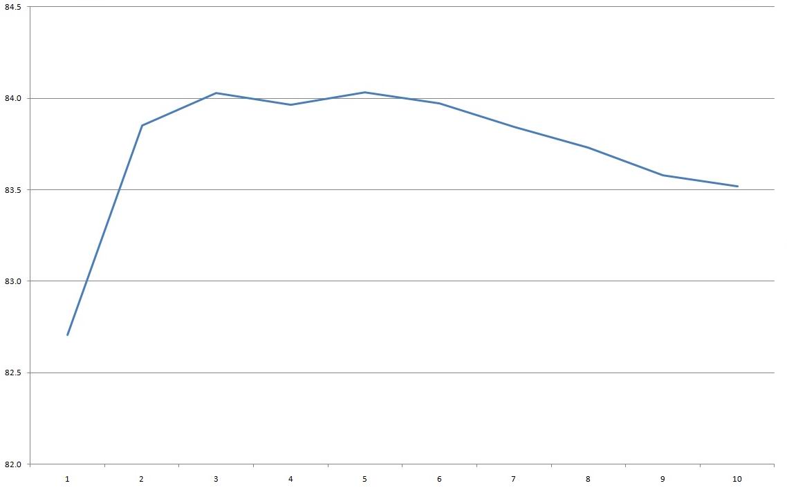
4. Efficiency is about 86%. I wouldn't call that particularly high, especially considering the topology and the fact that this is a 24 V power supply. The 350 W Mean Well rated for the same 24 V is specified at 88% efficiency. The graph shows efficiency from 1 to 18 A in 1 A increments.
Ripple.
As is usually the case with this topology, ripple is quite low, especially considering that this is a 24 V power supply: about 100 mV at 14 A.
Below are the results with no load and at 5, 10, and 14 A.
The low-frequency ripple is also pretty good overall. Only at maximum current do 100 Hz spikes start to appear, but they're small enough to ignore.
Everything looked good until I raised the load current to 15 A while measuring low-frequency ripple. That's when things got weird.
On the left is the waveform at the same 50 mV per division as above, for comparison; on the right, it's rescaled for measurement: almost 1 V.
It looks like this is how the power supply's power limit works, so 14 A is its maximum.
For the additional tests, I had to use an adjustable power supply to provide a 0–10 V control signal.
I also noticed that, due to the design of the power supply under review, some interference from the adjustable power supply gets onto the output when it's switched off, although it's not much.
With zero voltage at the output, there was still about 6 V, although logically it should have been zero. Raising the voltage even slightly immediately brought it to about 23 V. At 10 V, the output is fully on and we get the full voltage.
In fact, the voltage isn't regulated here; instead, the PWM duty cycle changes. The PWM frequency is about 18 kHz. I think they chose this frequency so the load wouldn't make an audible buzzing sound.
Waveforms with a 1 µF capacitor at the output (I forgot to remove it) and control voltages of 2, 4, 6, and 8 V. Under load, the waveform will actually look something like a square wave, but that's not important here.
Here I momentarily forgot that there was a capacitor at the output and tried loading the power supply. First I noticed a faint, suspicious smell, then a little smoke.
I switched it off and started looking for what was getting hot. It turned out to be the capacitor. I turned the load back on and checked it with a thermal camera.
The capacitor heats up very quickly: in just 13 seconds, it went from 98 to 123 degrees, and the temperature kept rising.
Consider this a warning. If the load connected to this power supply has capacitors at its input—for example, an electronic device—do not use the control signal under any circumstances. You can control something simple, such as an LED strip or an incandescent bulb. In theory, you could connect a brushed motor, but I wouldn't do that.
By the way, I almost forgot: when power is applied, the output voltage doesn't appear immediately; it ramps up gradually over a few seconds. Neat :)
Load tests.
Cold and unloaded, the voltage was 23.832 V.
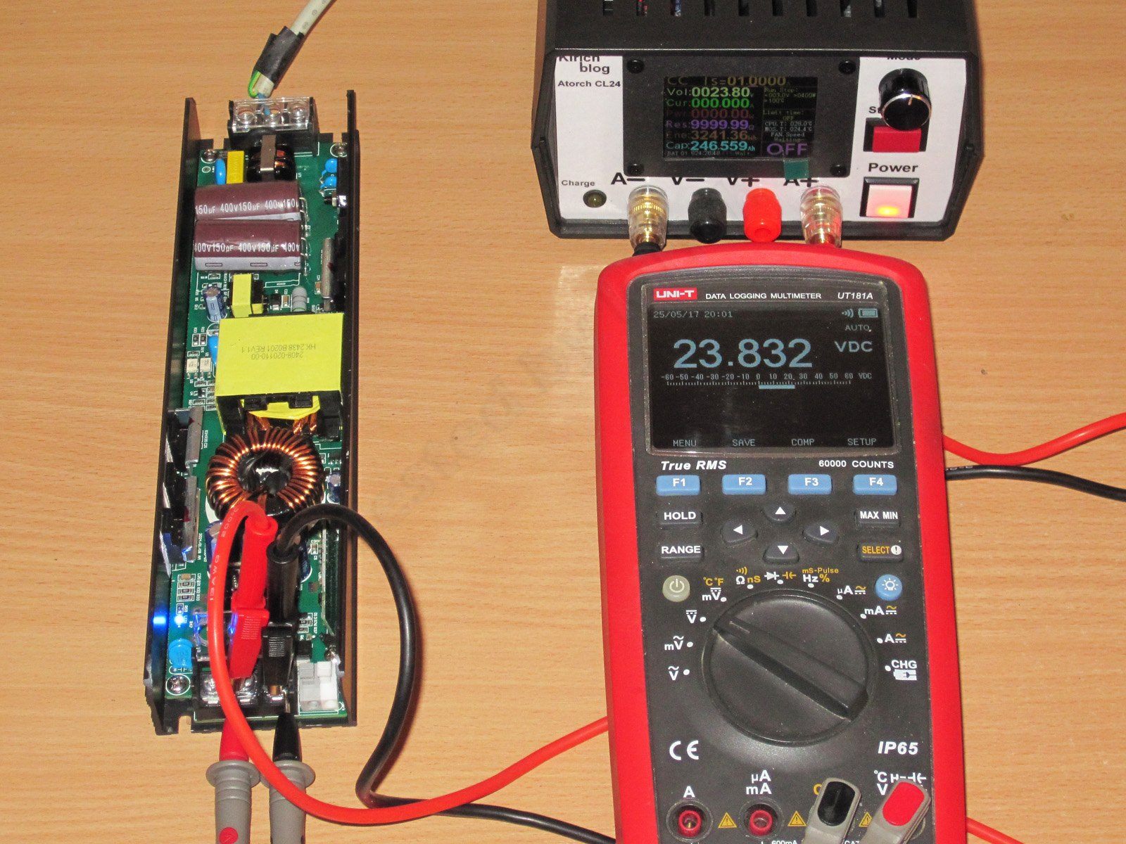
1. At 4 A, the voltage dropped to 23.739 V while the unit was cold.
2. With the unit warm and at 8 A, it dropped further to 23.605 V.
3. With the unit warmed up and at 12 A, the voltage dropped to 23.408 V.
4. Then, with the unit already hot, I reduced the load current from 12 to 10 A, and the voltage was 23.4 V.
5. After half an hour, with the unit hot and at 10 A, the voltage had risen slightly to 23.428 V.
6. With the unit hot and no load, the voltage was 23.758 V.
In short, the voltage does depend on temperature, but within acceptable limits. Its dependence on current, however, is quite significant. Not that it’s critical, but that’s how it is.

Now let’s look at the component temperatures. I won’t include the results at 4 A; I’ll show what I got at 8 and 12 A.
8 A — transformer 66 degrees, transistors 66 degrees, diode assemblies 71 degrees, inductor 87 degrees, one of the additional transistors 65 degrees.
12 A — transformer 93 degrees, transistors 103 degrees, diode assemblies 106 degrees, inductor 114 degrees, additional transistor 117 degrees.
Temperature-wise, my biggest concerns are the output inductor and the additional transistor. I think that transistor is what knocked the power supply’s efficiency down a bit.
Next, as an experiment, I reduced the load current to 10 A, so the power was around 240 W, and ran it like that for another half hour or so.
The results: transformer 92.3 degrees, transistors 91 degrees, diodes 95 degrees, inductor 110 degrees, additional transistor 96 degrees.
So 240 W is the maximum continuous power this power supply can deliver at room temperature.
After the heat test, I decided to take a closer look, so I removed the board from the case. There’s a thermal pad under the transformer, by the way, but I’d add another one.
It looks neat. You can also see another thermal pad at the bottom right; it carries heat away from the additional transistors.
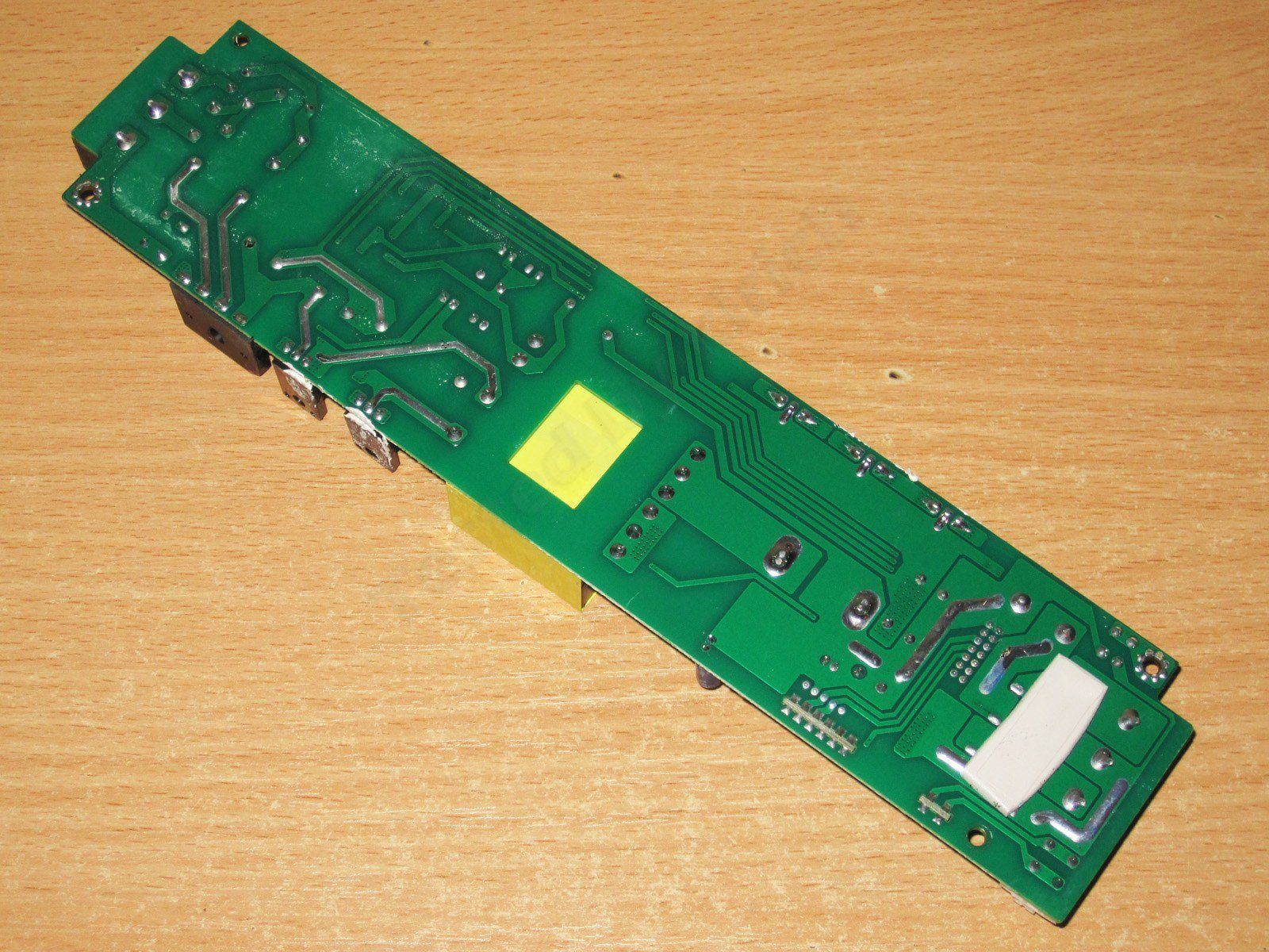
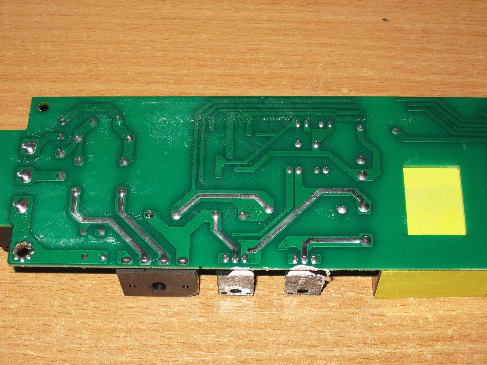
The board is a little dirty, but not too bad. There are no slots, but the clearances are sufficient, so I have no safety concerns either.
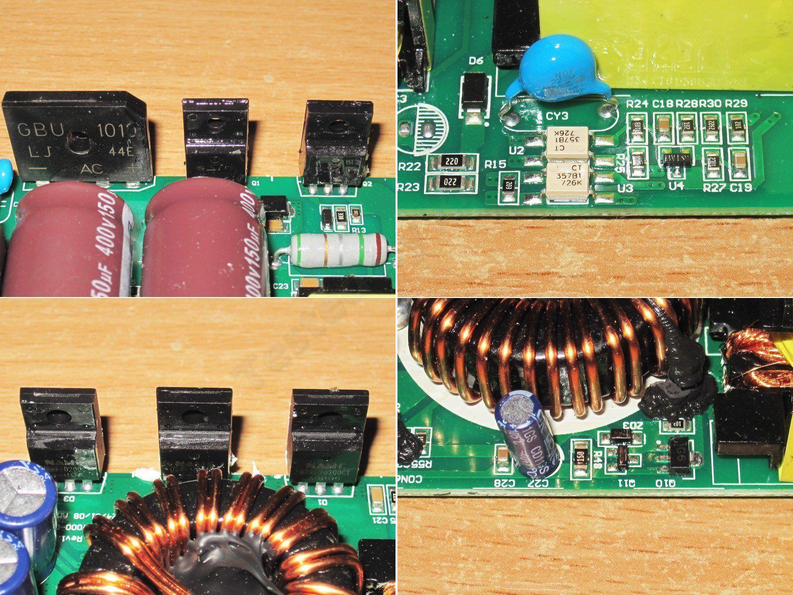
High-voltage section with the case removed.

1. The 18N50 transistors are rated for 18 A and 500 V, which is perfectly adequate.
2. The power supply has not only the main feedback loop, but also an overvoltage protection circuit on the output.
3. The output diode assemblies are rated for 20 A and 200 V. As a reminder, they aren’t connected in parallel here; they’re split into two groups. Since one “half” runs hotter, there are probably two assemblies in one leg and one in the other, which makes sense.
4. An additional voltage regulator supplies power to the auxiliary boards.
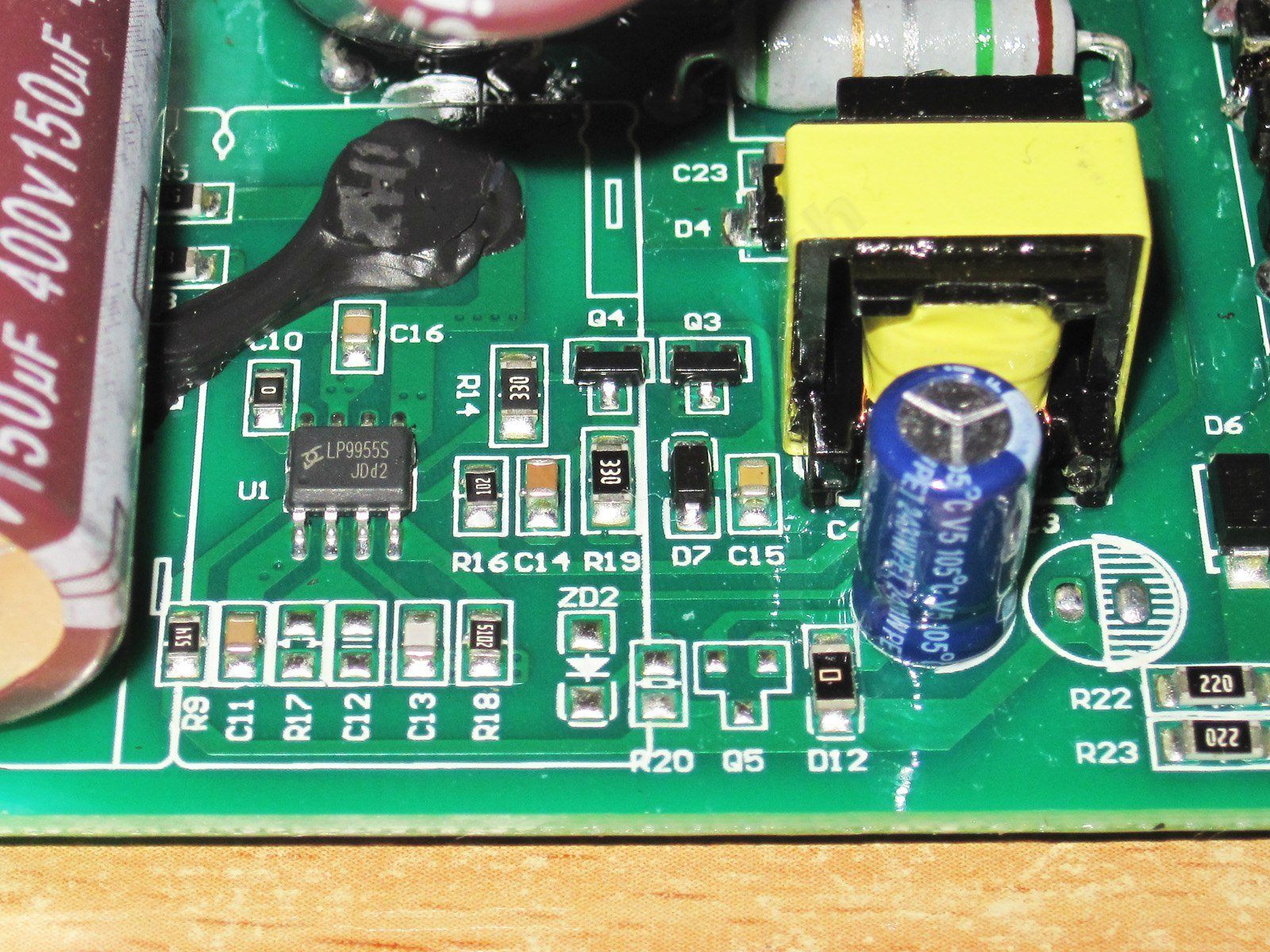
The PWM controller and its surrounding components.
If you didn’t notice, the thermal image of the transistors clearly showed one running hotter than the other. Here’s why: thermal paste covers only half the case on one transistor. That’s why I run the thermal test first and only then take the power supply apart.
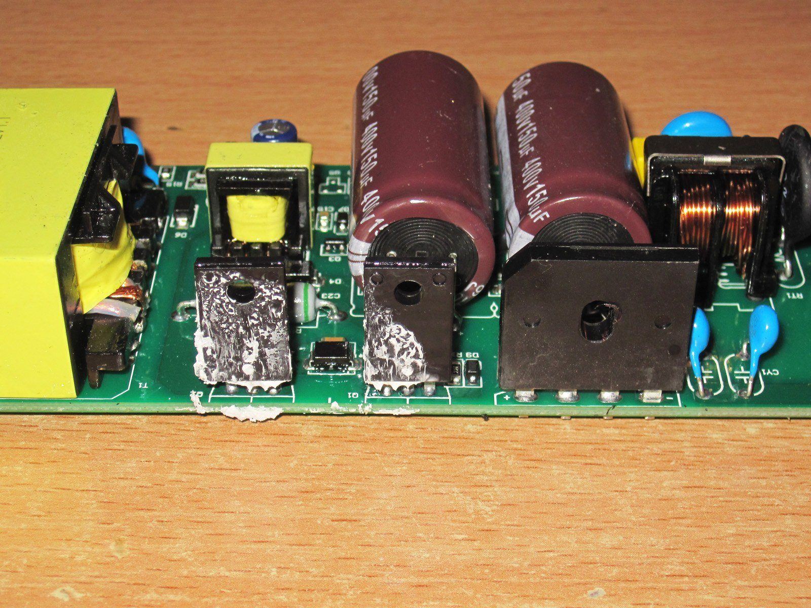
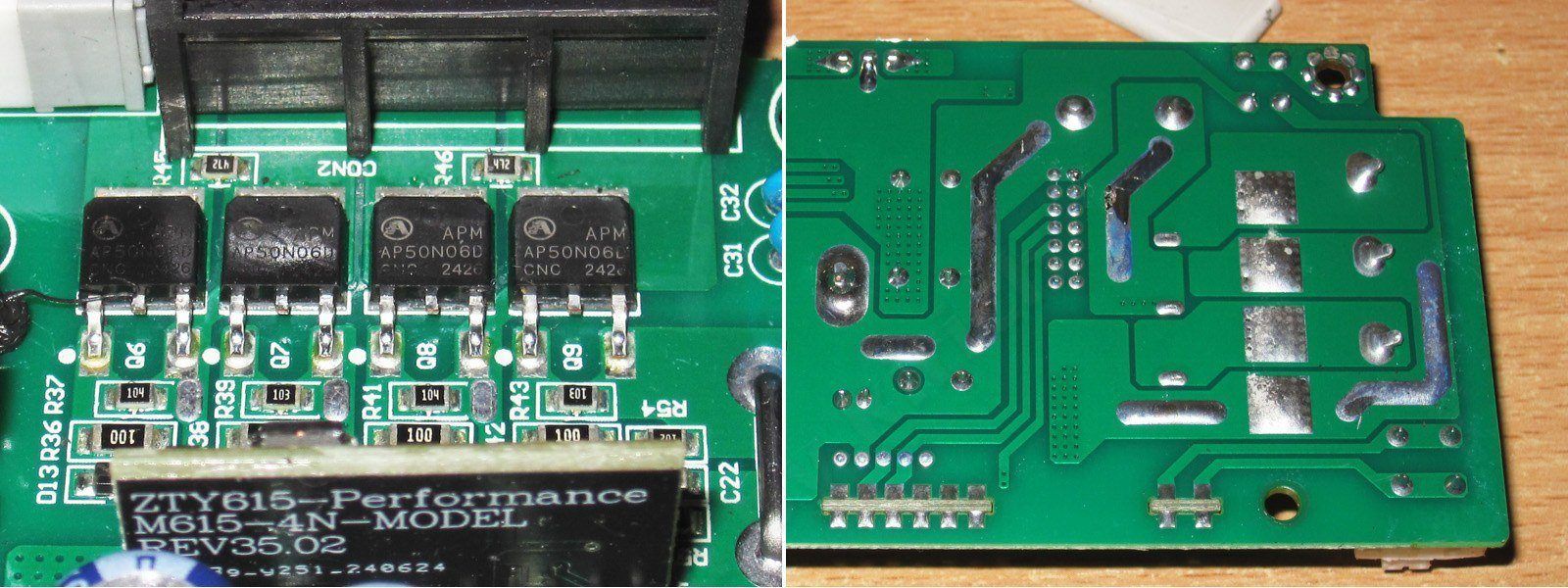
About the additional transistors. Remember I mentioned that the terminal block has an NC contact? It turns out the power supply actually has two channels, but the second one is disabled in software.
Each channel is handled by two transistors connected in a half-bridge configuration. The positive output is connected directly, while the negative side is switched by one of the transistors. The second transistor apparently shorts the output when there’s no control signal. I think this trick is meant to stop the LED strip from glowing due to interference.
At first I thought all four transistors were connected in parallel, but it turns out the circuit is much more complicated than that.
Conclusions.
I usually form my conclusions while writing a review: I sort through all the information I’ve gathered and then draw conclusions based on it. Here, though, I’d already formed my opinions and conclusions during testing, because I actually liked these power supplies, even if not everything about them.
The first power supply is a perfectly honest unit for 100 W continuous and 120 W short-term. The build quality is quite good; they clearly cut corners on some components, but within reason.
For the second power supply, I’d say its honest continuous power is around 200–240 W, with a maximum of 280 W. The build quality is also good, and the components are clearly better.
Overall, both power supplies left a very good impression. They’re neatly assembled, the board is coated with protective varnish, and they’re even kind of attractive. There are a few minor flaws, but the main issue is the stated power and specifications. What kind of 400 W are we talking about? The first unit can really deliver only 25–30% of its rated power; the second does better, at around 60%. But honestly, claiming 400 W for a unit that can’t deliver that much even “in a sprint” is ridiculous. At least the protection is set up reasonably well, so it’ll be hard to overload them.
A note about protection. As you’ve seen, temperature is the main problem. And what’s striking is that the vast majority of these power supplies have no thermal protection. Even more striking, in the vast majority of cases the PWM controller can monitor temperature; they just don’t install a thermistor, replacing it with a “dummy” component. How does that make any sense?
Now, about power. I specify continuous power at room temperature. If you install the power supply in an electrical panel, you need to derate it, because the air temperature there will clearly be higher. And here we’re back to the question of whether it has thermal protection. In short, there’s still room for improvement—and for giving the power supply manufacturers a nudge.
That’s all for today. I hope this was useful, and thanks again to Vitaly for providing the power supplies for testing.
This page was found when searching for:
1
1
This model is included in the summary table: Comparison of power supplies: ripple, efficiency, and temperature rise
The figures from this review are in the measurement database: Power supplies
Calculate manuallyAll calculators
Discounted products
You may be interested in



Discounted products
Support the project
All the content on the site and the advice are free, but we’d be grateful for your support of the project and the channel!
Discuss on the forumHave a question or some experience to share? Discuss the article with the author and readers: the forum is a convenient place to share schematics and photos.
Go to the forumOnly registered readers can comment. It takes a minute to sign up, and you can log in with the same account you use on the forum.
Log inRegister