
RD6012H, a very interesting converter from Riden
$95.45
A reminder: to keep up with new posts on the blog, I recommend following me on Instagram, where I’ll post notifications about all new articles and might also write about something interesting - link to my account
You can also subscribe to updates and new articles on the Telegram channel - https://t.me/KirichBlog
I’ll start the review by listing my reviews of all the products from this company that I’ve tested.
DPH5005
DPS8005
DPS5020
RD6006
RD6012
RD6018
RD6006P
RD6012P
RD6024
RK6006
Enclosure and power supply for the RK6006
RD6030
Silicone case covers
RD 25A cable set
RS485 module with galvanic isolation for connecting RD60xx series converters
RD6018P
The packaging is in the company’s usual style: the module is wrapped in foam and packed in a foam box, so it’s quite difficult to damage.
As last time, they included a booklet advertising various models.
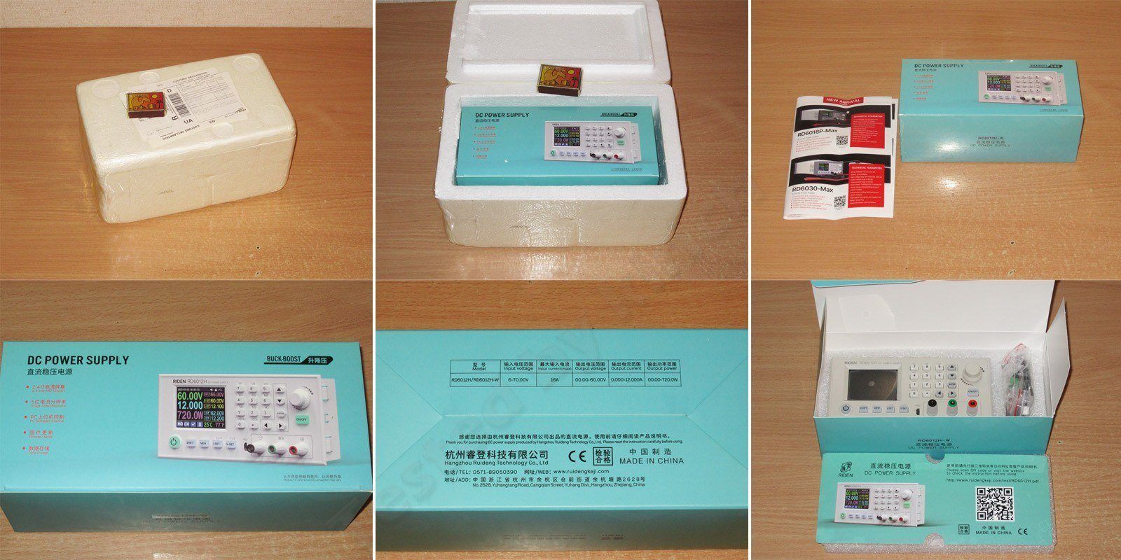
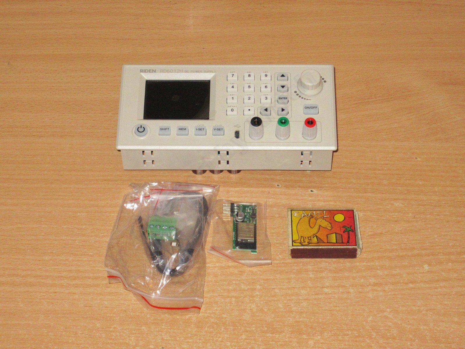
I ordered the version with the W suffix, so the package includes:
1. The RD6012H module itself
2. External temperature sensor
3. Terminal block
4. A pair of terminals for connecting to the power supply
5. Fuse
6. WiFi module, included with the W version.
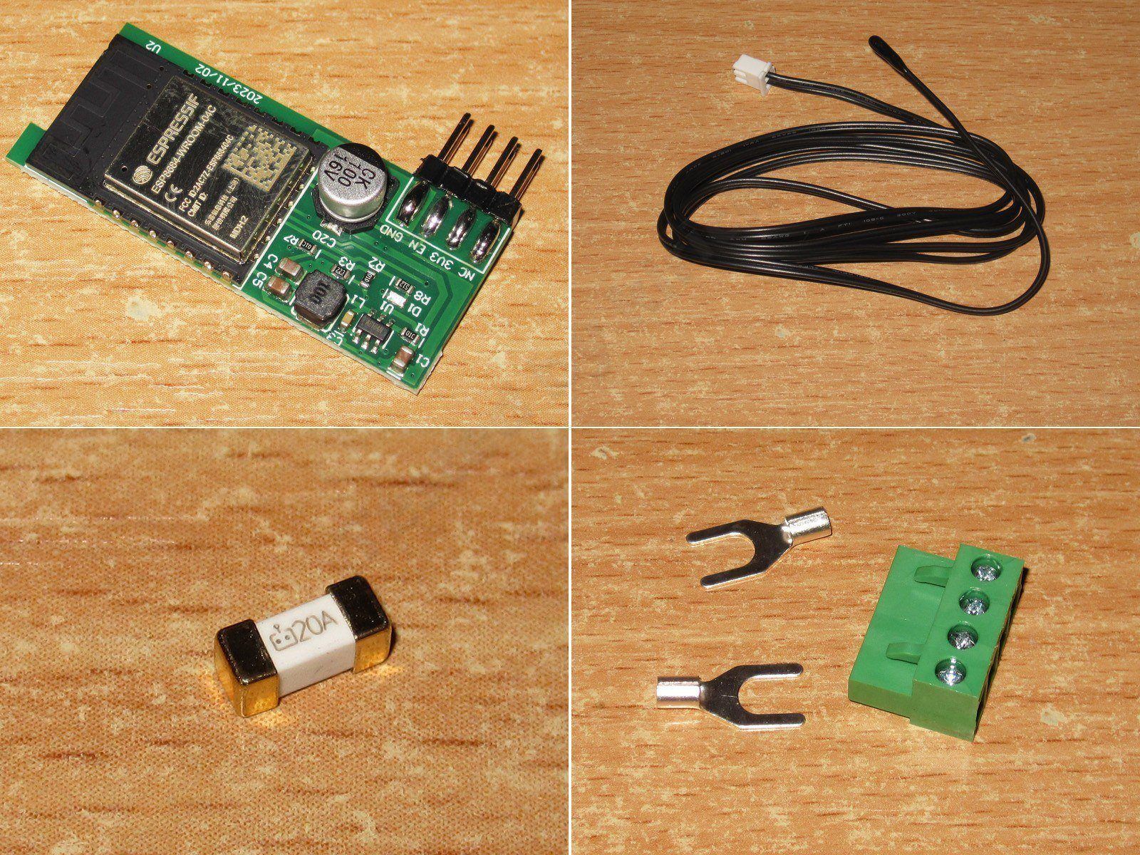
1. The WiFi module looks different from the ones I’ve had before.
2. A standard external temperature sensor, included with all these converters
3. 20 A fuse
4. Terminal block and terminals.
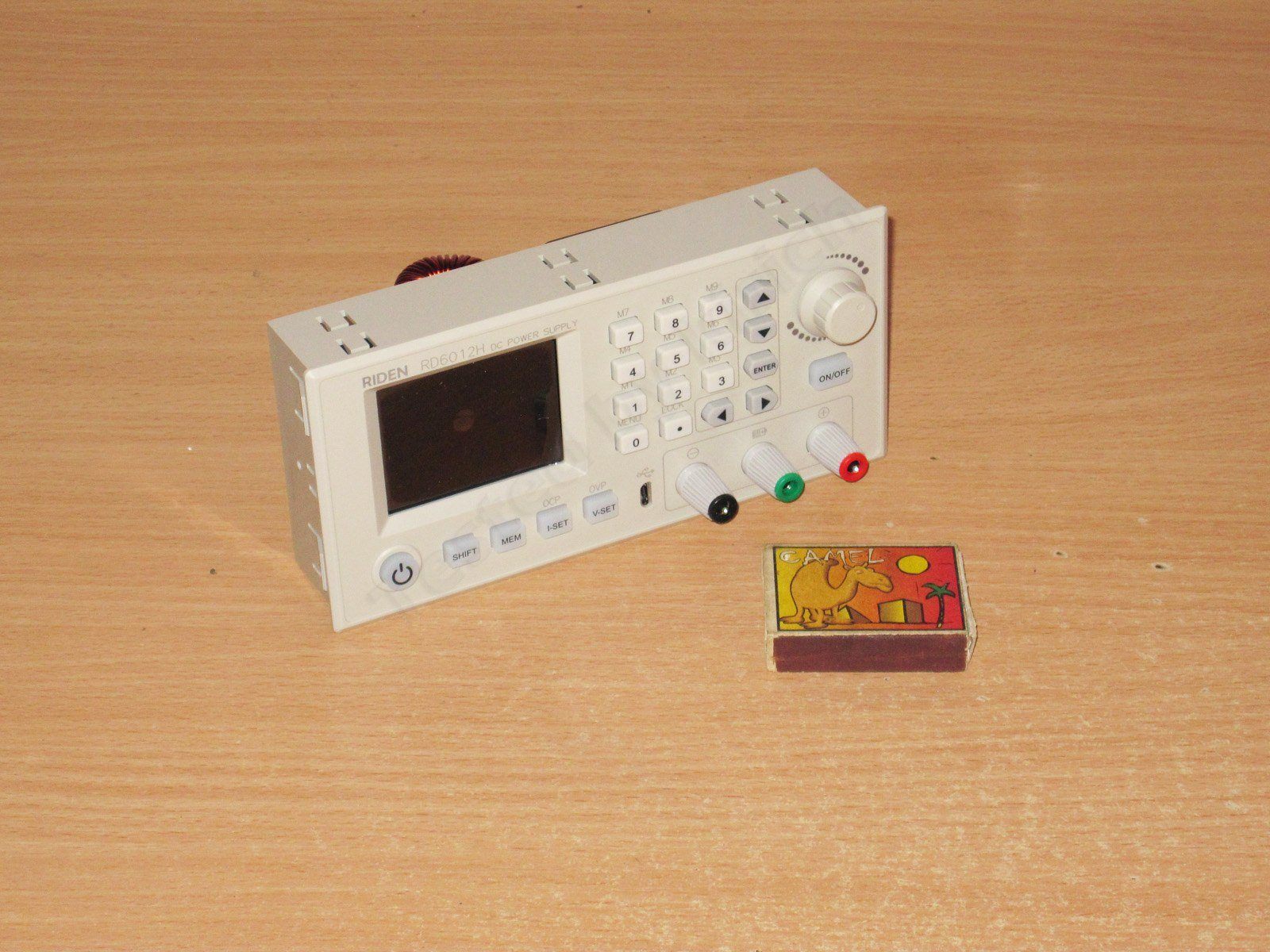
There’s no point describing the appearance; it’s exactly the same as the other models, except for the MAX series.
Here are the technical specifications:
Model: RD6012H/RD6012H-W
Input voltage range: 6-70.00V
Max input current: 16A
Output voltage range: 0-60.00V
Output current range: 0-12.000A
Output power range: 0-720W
Output voltage accuracy: 0.3%+30mV
Output current accuracy:0.5%+5mA
Output ripple typical:75mV VPP
Working temperature range: -10℃~40℃
Working mode: Buck boost mode
Over temperature protection: System temperature>80℃
Screen: 2.4 inch color HD display
Weight(with package):About 0.61kg
Product dimension: 167*81*65mm
When I first saw the new model, I didn’t even understand what was so special about it. The table listing the specs of all their converter models helped: one of the first things it mentioned was the topology—Buck-Boost.
Then it immediately became clear that this was a logical follow-up to the DPH5005, which could also deliver the full 60 V not only from a 55 V input, but, for example, from 24 V as well.
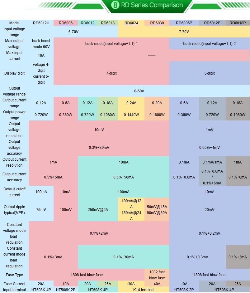
Of course, someone will ask: why would you need this when it’s easier to buy a power supply with a higher output voltage?
There are at least two answers:
1. If you want to use a name-brand power supply rather than a no-name one, you may be in for an unpleasant surprise. Brands usually offer 24, 36, and 48 V models, sometimes 54 V, but practically never 60 V, let alone 70 V. With this converter, you can buy a quality 48 V power supply and use it.
2. Battery power. Of course, someone might say that you can power an ordinary converter from batteries too. Not if you want up to 61 V at the output: to get the same 68–70 V from a discharged battery, the voltage from a fully charged one would definitely exceed the maximum input voltage, so you’d need a preregulator.
3. Also, some people may want to use a regular 50 Hz transformer, and that has almost the same problem as batteries: the output voltage of a transformer-based power supply varies considerably depending on the input voltage and load current.
The manufacturer even shows one way to power it using their standard enclosure. And by the way, another advantage of this setup is that if you don't need full power often or for long periods, you can install a battery and a relatively low-power charger in the case. The battery provides high power, while the charger handles lower power over longer periods.
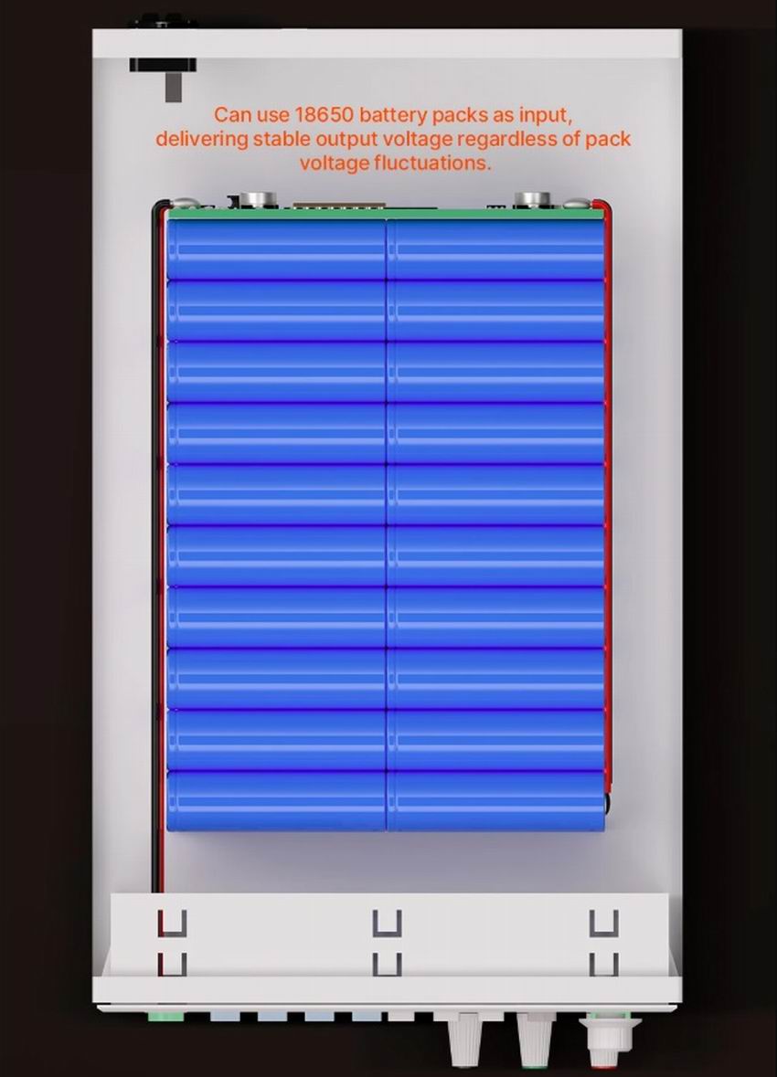
All of this made the hardware review much more interesting to me than usual.
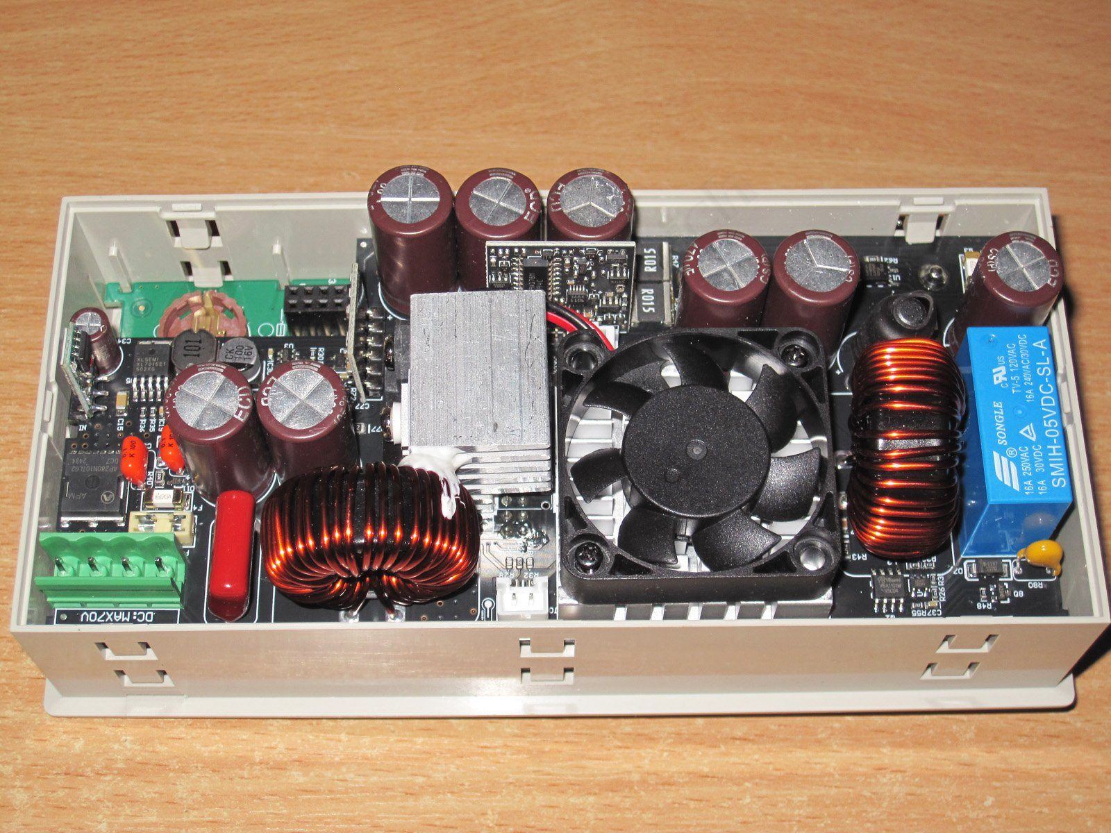
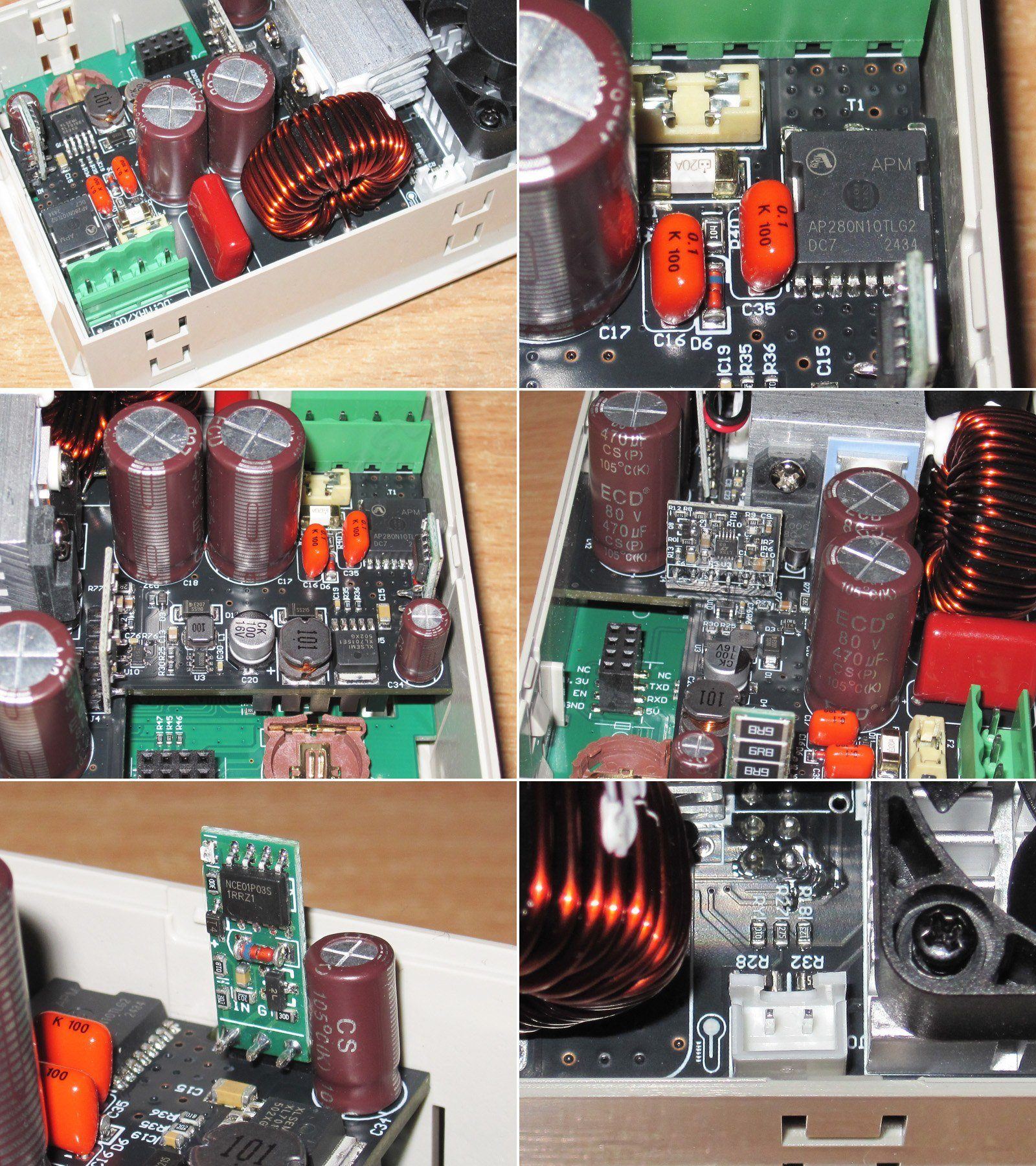
First, a couple of photos showing the unit from both sides.
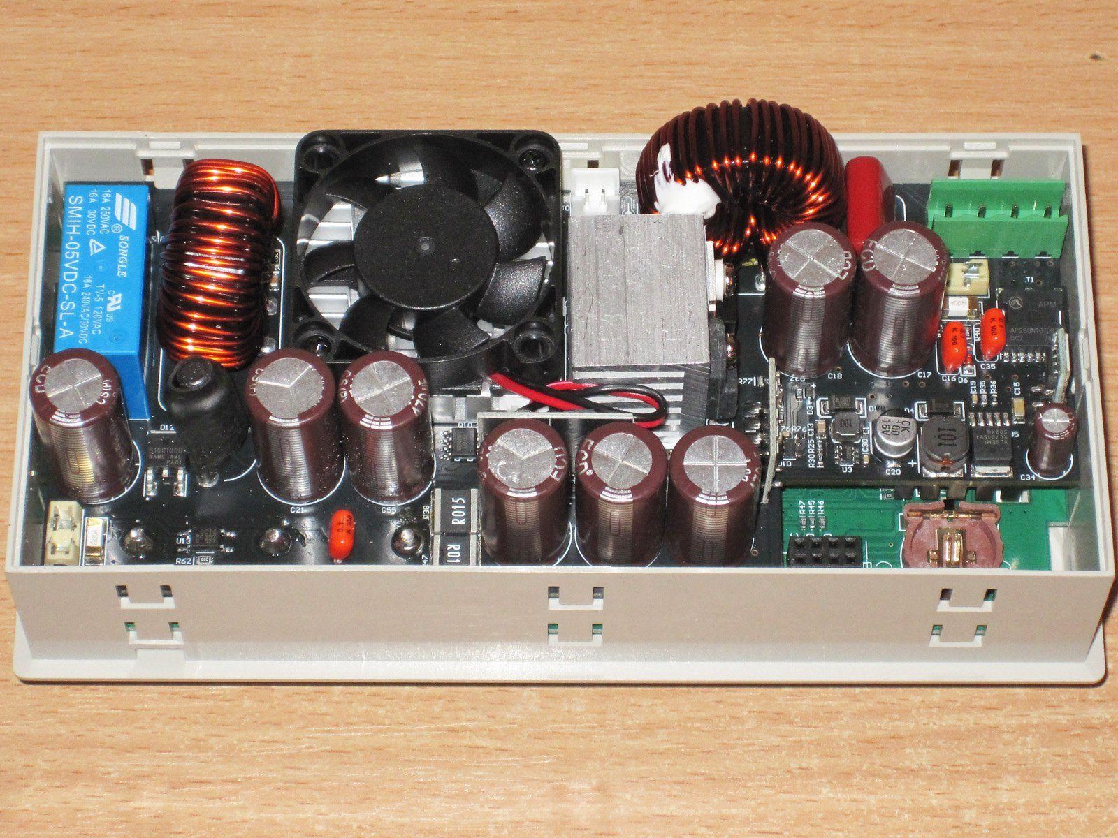
1. There's an inductor at the input, but in this case it's not the usual common-mode choke; it's the energy-storage inductor for the step-up DC-DC converter.
2. A fuse and reverse-polarity protection transistor are installed nearby. There's also a fuse holder next to them. If the original fuse has blown, though, I strongly recommend first checking that the converter works by installing a fuse in the holder. If everything is OK, solder the replacement into the original fuse's place. The holder is rated for a maximum of 10 A.
3. Auxiliary converter section.
4. There are lots of capacitors, all large 470 µF, 80 V parts.
5. A small board that, if I'm not mistaken, provides input overvoltage protection.
6. As usual, the connector for the external temperature sensor is hidden away. By the way, in the store photo they accidentally labeled the fan connector the same way too, so don't mix them up: there's only one sensor, and it plugs in here.
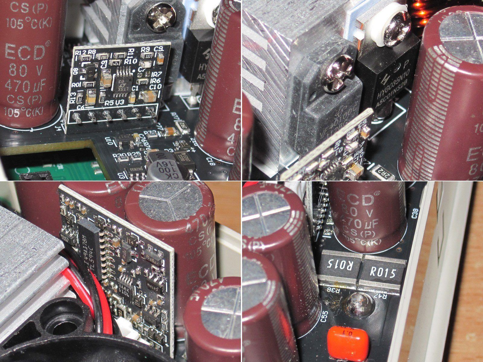
1. PWM controller submodule for the step-up DC-DC converter.
2. The step-up converter's diode and transistor. Note that there's no thermal paste on the diode, which isn't good.
3. PWM controller submodule for the step-down DC-DC converter.
4. A pair of high-power shunts responsible for measuring the output current.
So the main board has three submodules, and the layout is clearly very cramped. There wasn't even room for an input inductor.
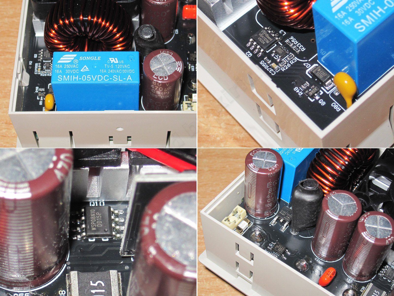
1. Relay that connects the battery charging terminal.
2. Some kind of mystery circuit near the relay; there's also a polymer fuse on the right.
3. Near the shunts, I found something that, judging by the markings, is probably a transistor. I suspect it's part of the current regulator that discharges the output capacitors.
4. There's also a fuse on the output, along with an inductor to reduce ripple and a protection diode. If I'm not mistaken, it's connected across the output and blows the fuse if, for example, you connect a battery with the wrong polarity to the main output (not the charging output). The charging output has reverse-polarity protection; the relay simply won't switch on.
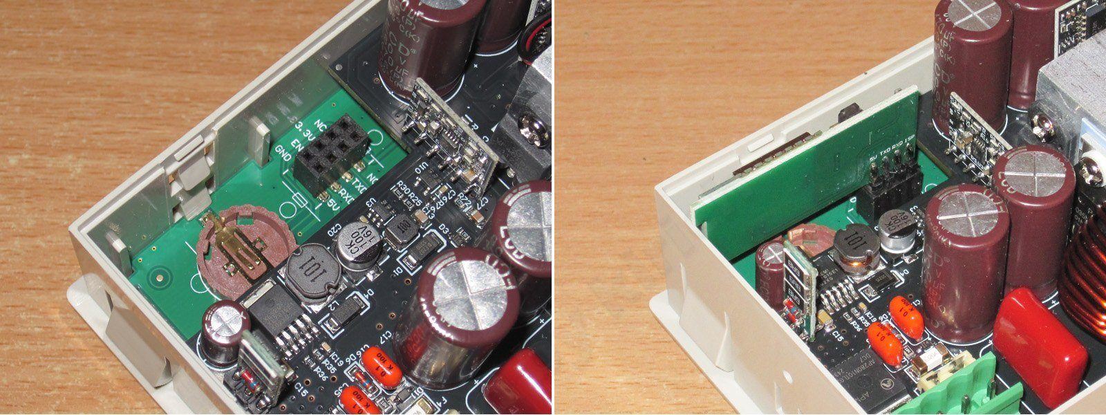
The usual spot for installing a WiFi module, but there have been some changes. The old module was trickier to install, but it was held more securely by a case latch. Now it's easier to install, but also easier to knock loose.
Next, we remove the power board. To do that, you first have to desolder the three output terminals. I have to say that, unlike on previous models, they were somehow harder to desolder—though maybe that's just my impression. The negative terminal was especially stubborn.
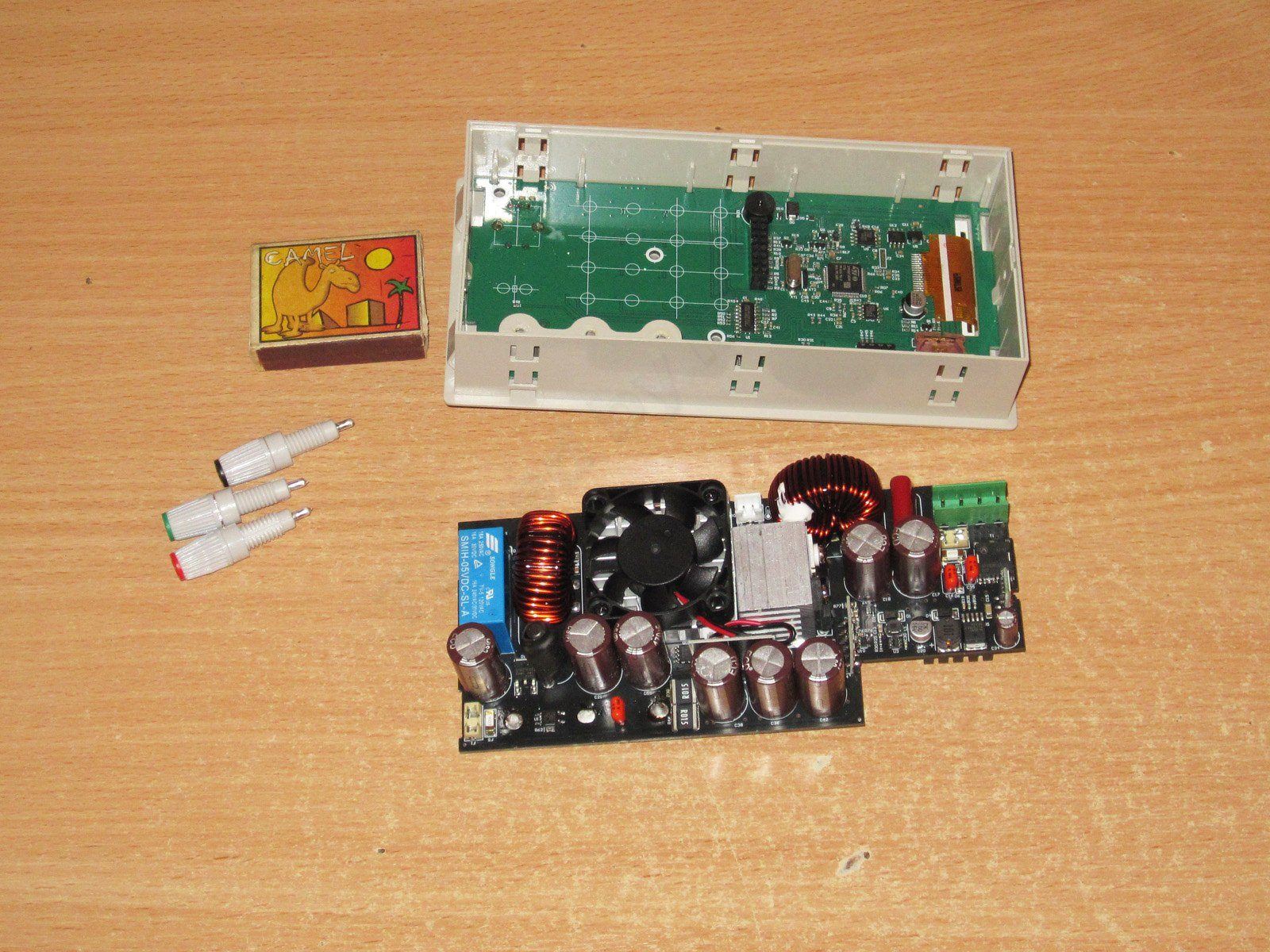
Next, bend back the latches and remove the board. It's very easy.
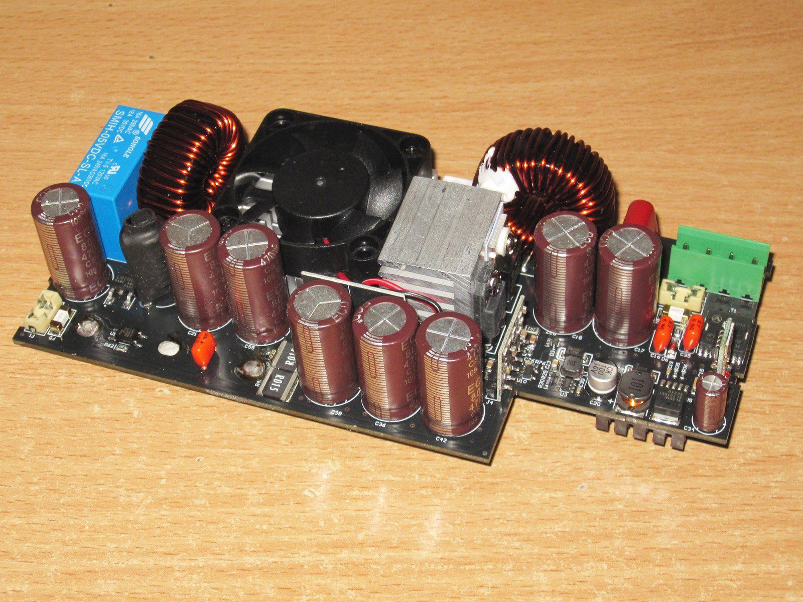
A few more detailed photos of the top side.
1. Auxiliary converter section.
2. Step-up converter PWM section.
3. Terminal near the shunts. This one was the hardest to desolder. In general, I strongly recommend not desoldering these terminals "just out of curiosity."
4. Output filter section.
The output capacitance is quite substantial, so checking things like LEDs can have its "quirks." Either learn how to do it properly or buy something like the RD6006P.
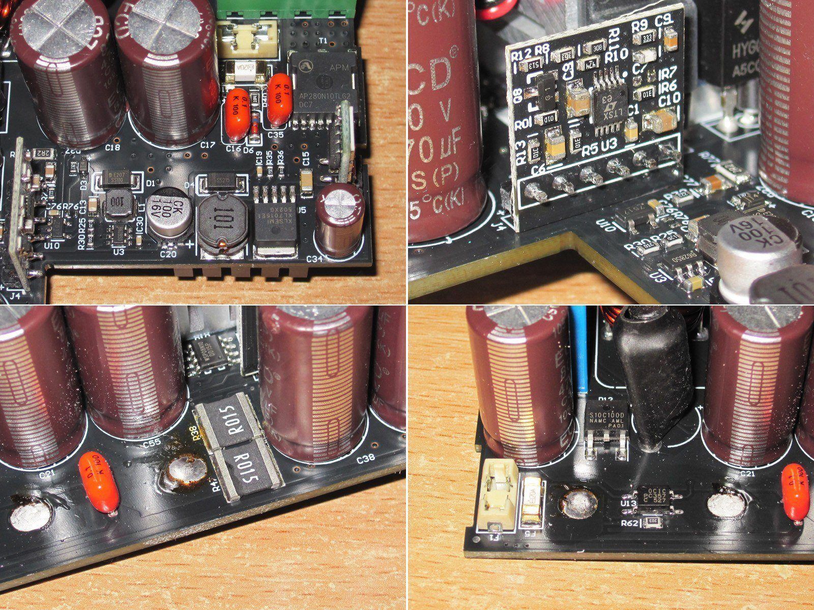
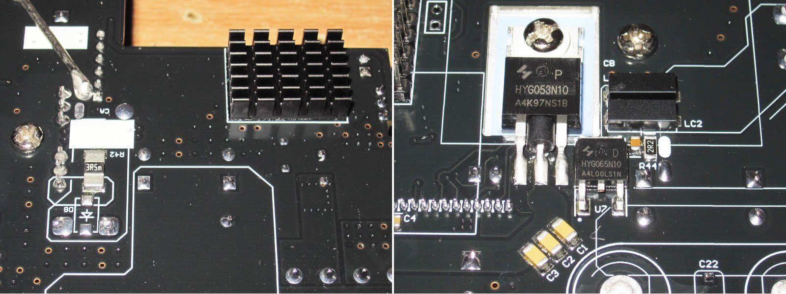
It's almost empty here. You can see that in one spot there's either a heavy-duty jumper or a reinforced trace.
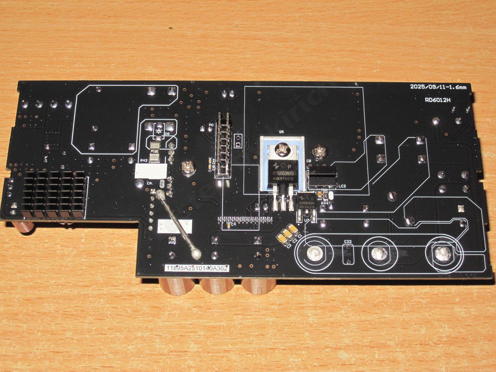
1. Step-up converter shunt, rated at 3.5 mΩ, which is fairly uncommon. The heatsink for one of the auxiliary DC-DC converters is at the top right.
2. Step-down converter section. I like the two inductors to the right of the transistor, as well as the overall neatness of the assembly.
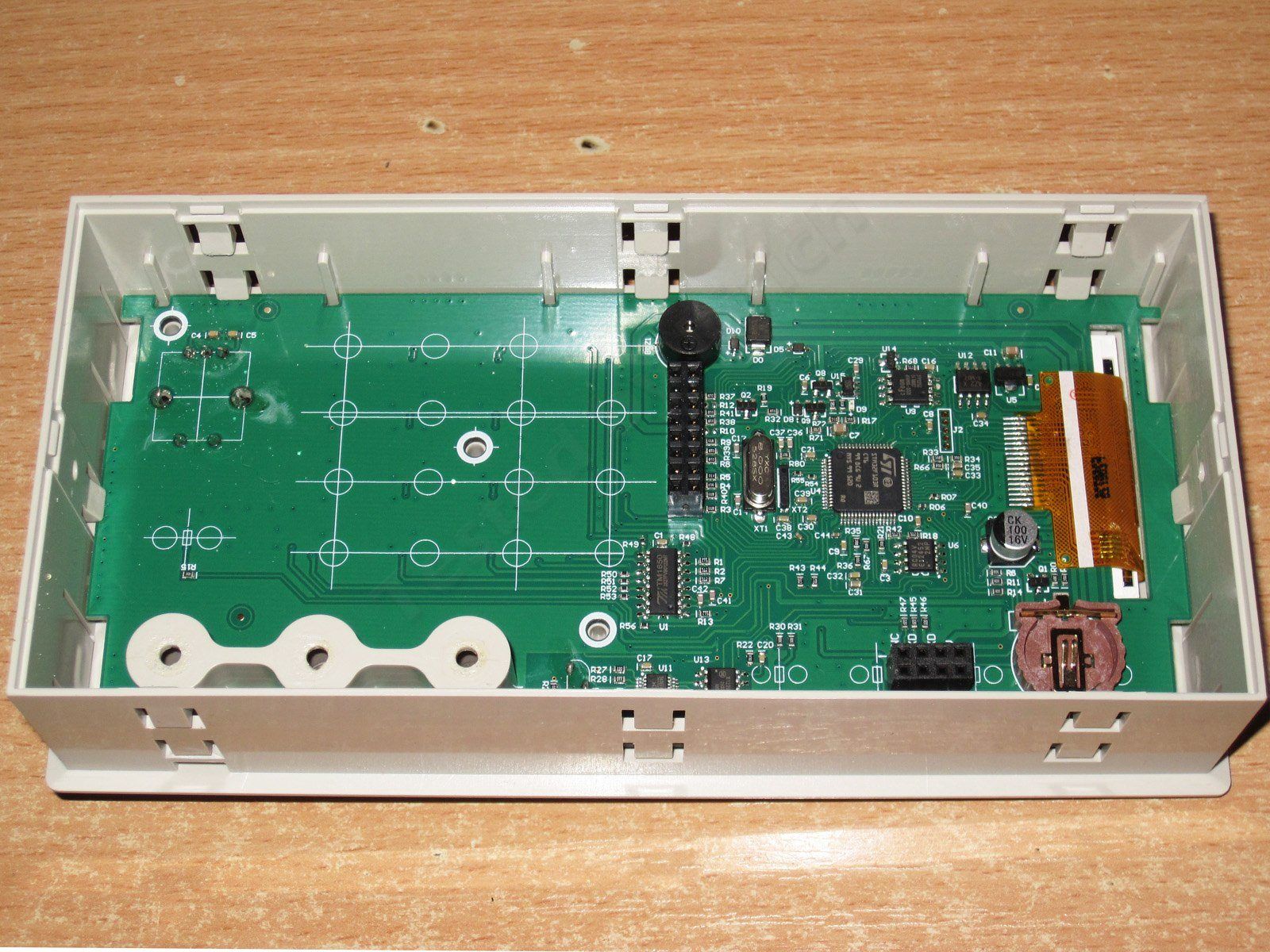
Overall view of the controller board. I hadn't noticed before, but they use a 30-pulse encoder rather than the usual 20-pulse one.
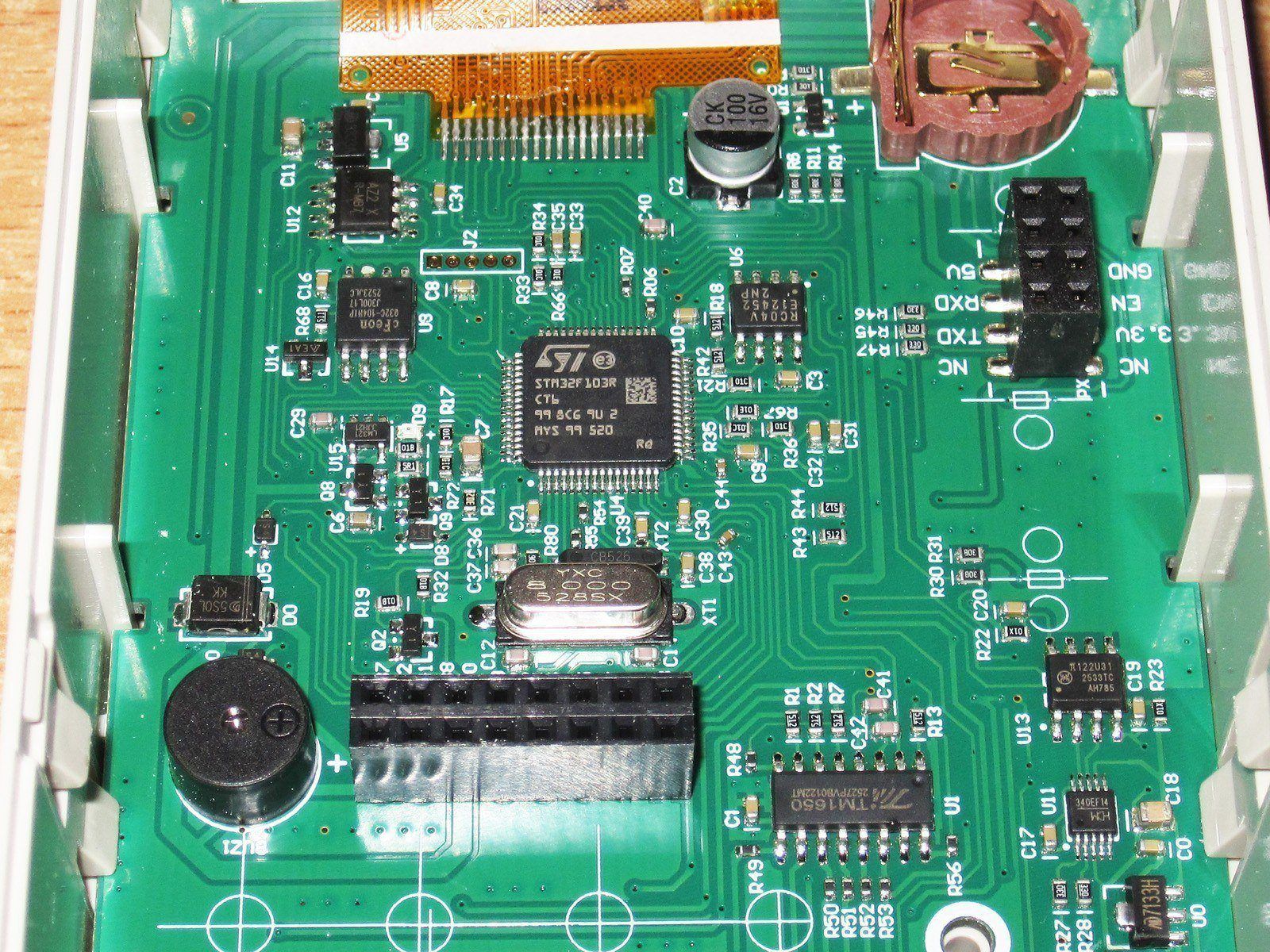
The converter's "brains."
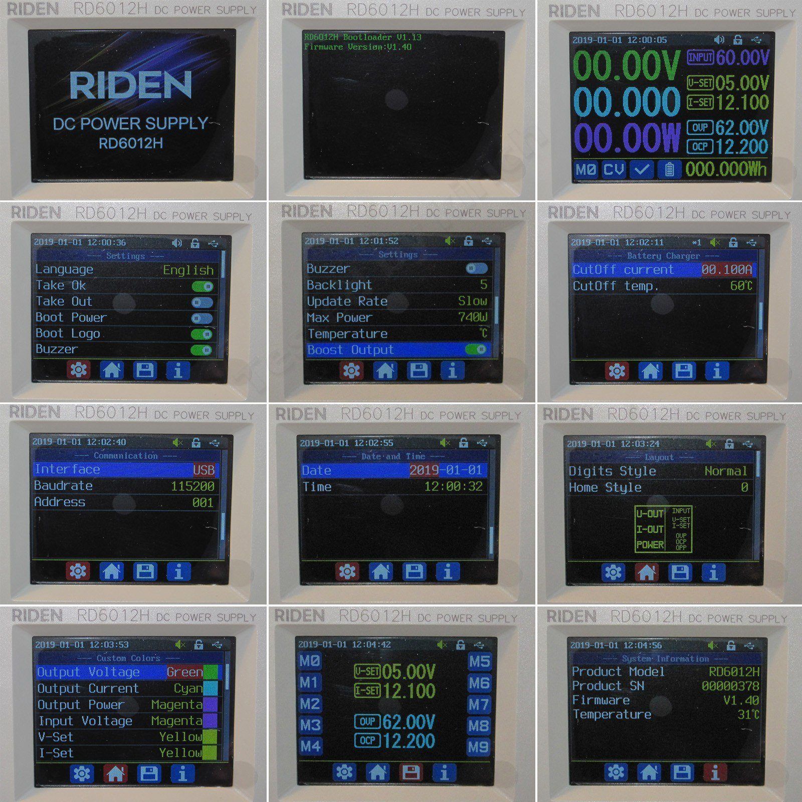
When powered on, it displays a splash screen with the model name. The bootloader screen came up by accident. I was toggling the power on and off to photograph the splash screen, and accidentally brought up the boot screen.
The main screen is the same as in the previous versions. The only thing I noticed is that the voltage setting line has a V next to it, while the current setting line has no A—it just didn't fit :)
Basically, the only difference in the menu compared with all the other versions (apart from the power rating) is one item: Boost output.
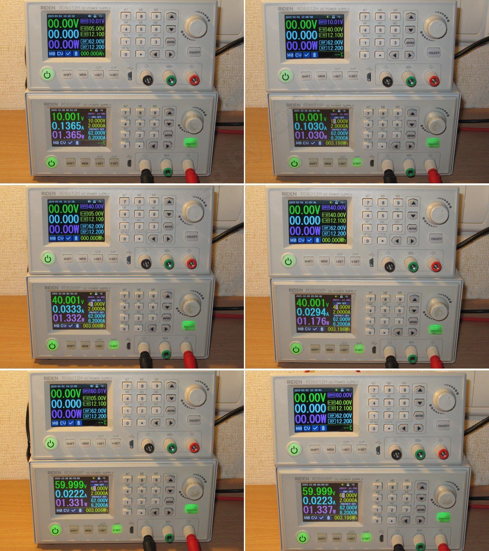
The tests follow, and first up is power consumption. There are two versions of this test.
Both tests were run with input voltages of 10, 40, and 60 V. The left side shows boost mode enabled, the right side with it disabled.
At input voltages of 10 and 40 V, enabling boost slightly increases the no-load current draw. At 60 V, there is no difference (check the reading on the lower power supply).
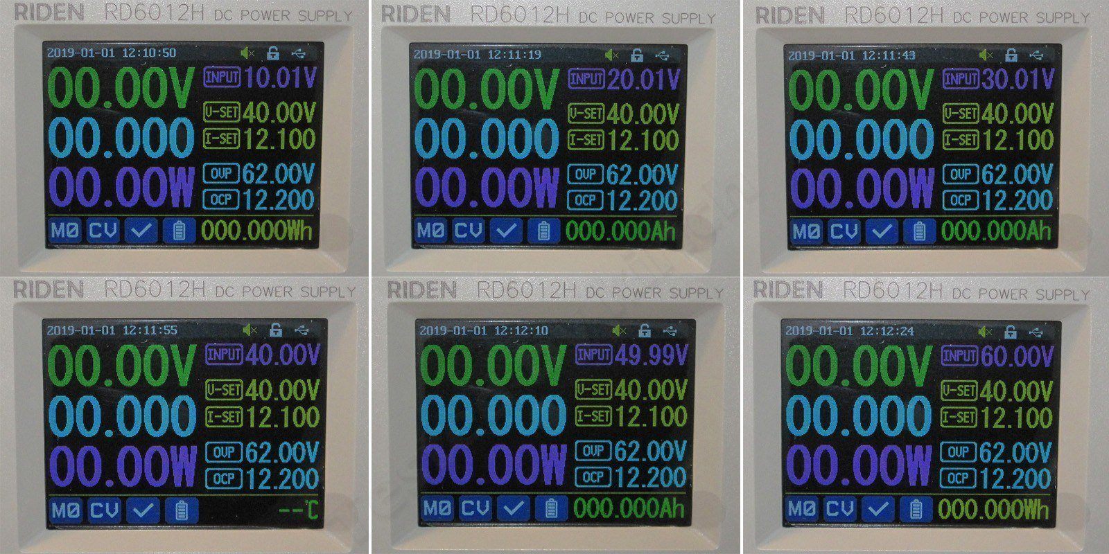
First test: checking the input voltage measurement accuracy. I tested at 10, 20, 30, 40, 50, and 60 V, and there were no complaints anywhere—the maximum error was 0.01 V.
Second test
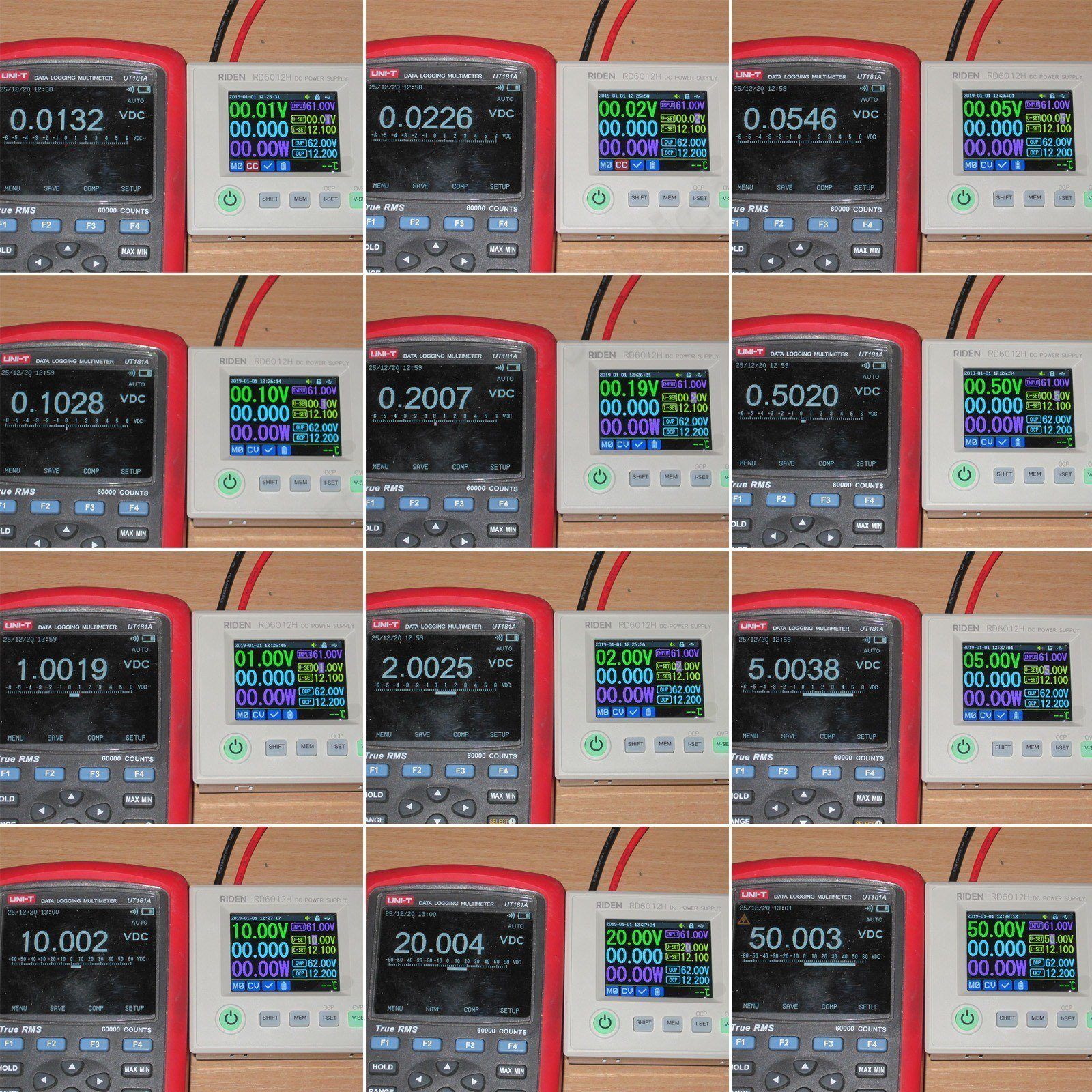
Output voltage setting and measurement accuracy. I tested from 0.01 to 50 V using a 1-2-5 sequence.
There are minor discrepancies below 0.1–0.2 V, though can a difference of 0.002–0.004 V really be considered a problem?
So, it passes this test. I'm more than satisfied.
Third test.
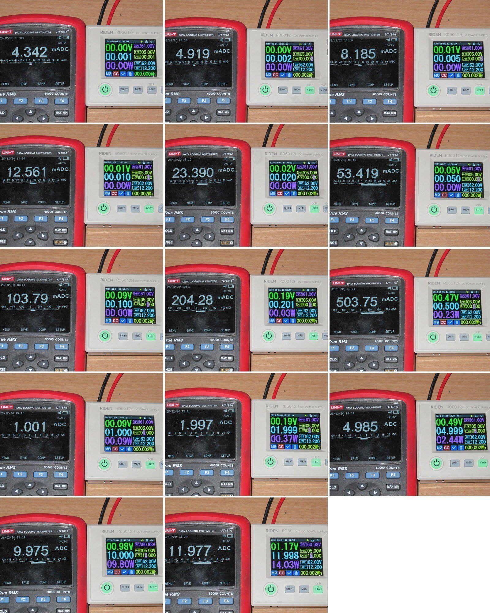
The same test for current, from minimum to maximum, using the same 1-2-5 sequence, with an additional check at 12 A at the end.
There are some issues at low current levels: the reading is high up to around 100–200 mA. Above that, there is still a difference, but it's relatively small compared with the set value.
Overall, it's quite good, especially considering that everything here is measured and set using a single shunt. With the multimeter, I used at least two ranges: up to 600 mA and up to 10 A. So, in my opinion, getting this level of accuracy with a 7.5 mΩ shunt across a range of 1 mA to 12 A is more than respectable.
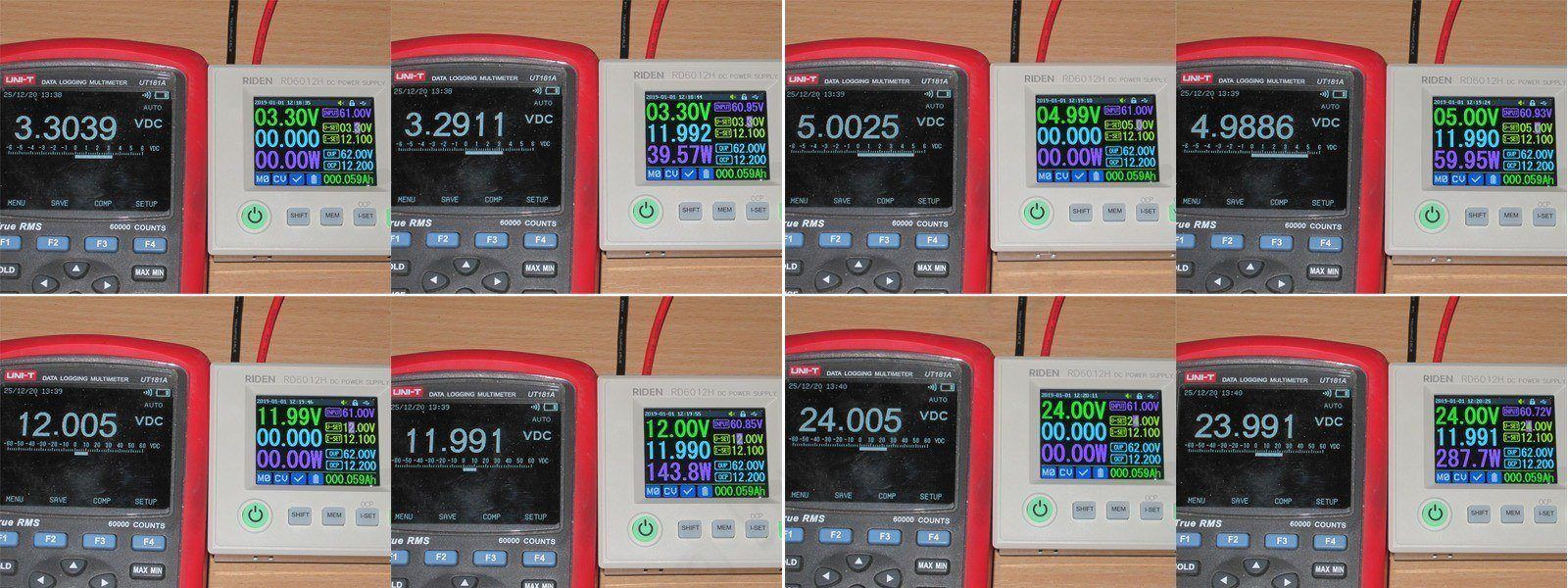
Fourth test: output voltage regulation under load.
I set the voltage to 3.3, 5, 12, and 24 V, then measured it at the power supply terminals with no load and at the full 12 A.
The difference was about 10–12 mV, which is excellent in my opinion. Sure, there's no four-wire connection here, but the measurement current is clearly set correctly, and at least on the converter side, at its terminals, everything is stable. Some of those 10 mV can easily be dropped across the banana plugs themselves, from the outer to the inner part of the terminals.
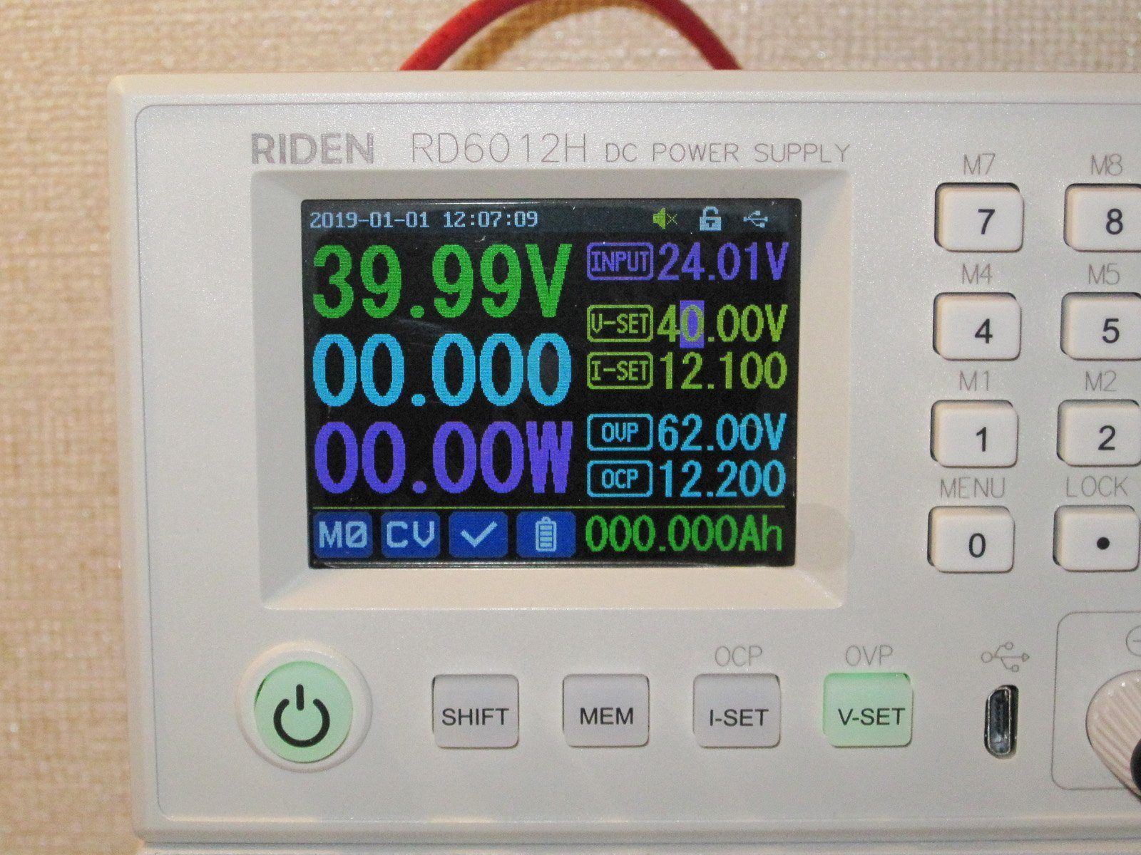
Fifth test: measuring the voltage drop across the power stage, basically to find out what minimum input voltage is needed to get the required output voltage.
And since this isn't a conventional step-down converter, there are a few things to keep in mind.
If I simply apply, say, 24 V to the input right now, I can easily get 40 or even 60 V at the output.
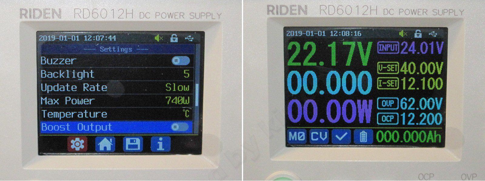
So I go into the menu and disable boost mode. The converter then essentially becomes a regular RD6012, and with the same 24 V input, we get about 22 V at the output.
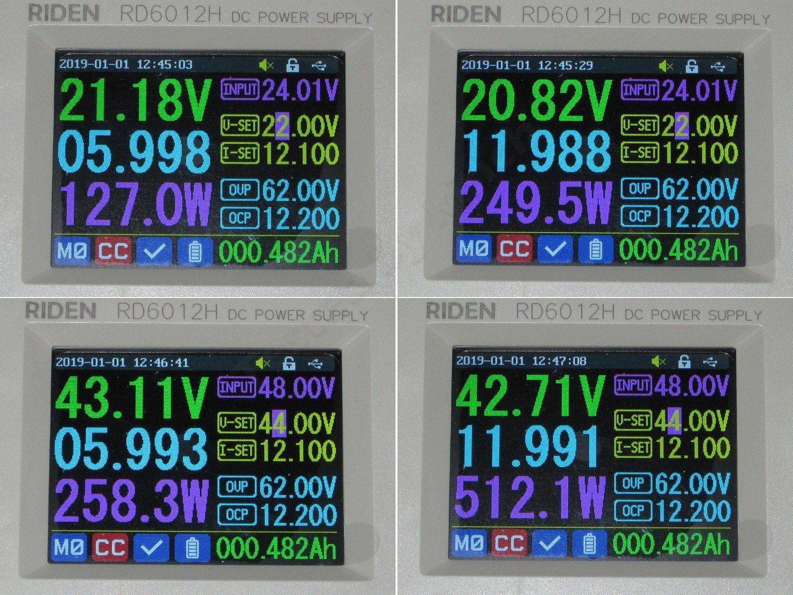
I tested with two input voltages, 24 and 48 V, and two load currents, 6 and 12 A.
At a 24 V input, the minimum voltage drop was about 2.8 and 3.2 V at 6 and 12 A, respectively.
At a 48 V input, it was higher: 4.9 and 5.3 V, respectively. So to get 61 V, you need to supply at least 68–70 V to the input, unless you're using boost mode, of course.
But it would be much more interesting to run the same test with boost mode enabled.
A small side note: step-down converters are usually rated—and effectively specified—by their output current, while step-up converters are rated by their input current. The point is that the input current is what matters here. Since the stated maximum input current is 16 A, getting 720 W of output power requires at least 720/16 = 45 V at the input.
So if the input is, say, 12 or 24 V, we'll get up to 12 × 16 = 192 W and 24 × 16 = 384 W, respectively.
But let's see how it performs in practice.
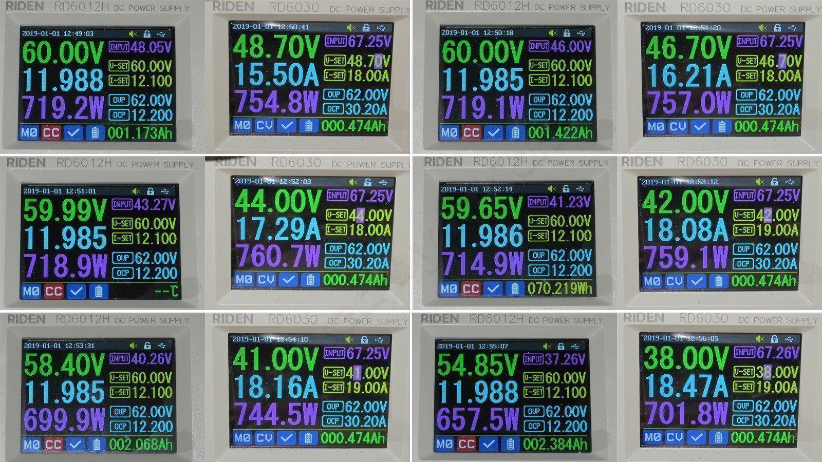
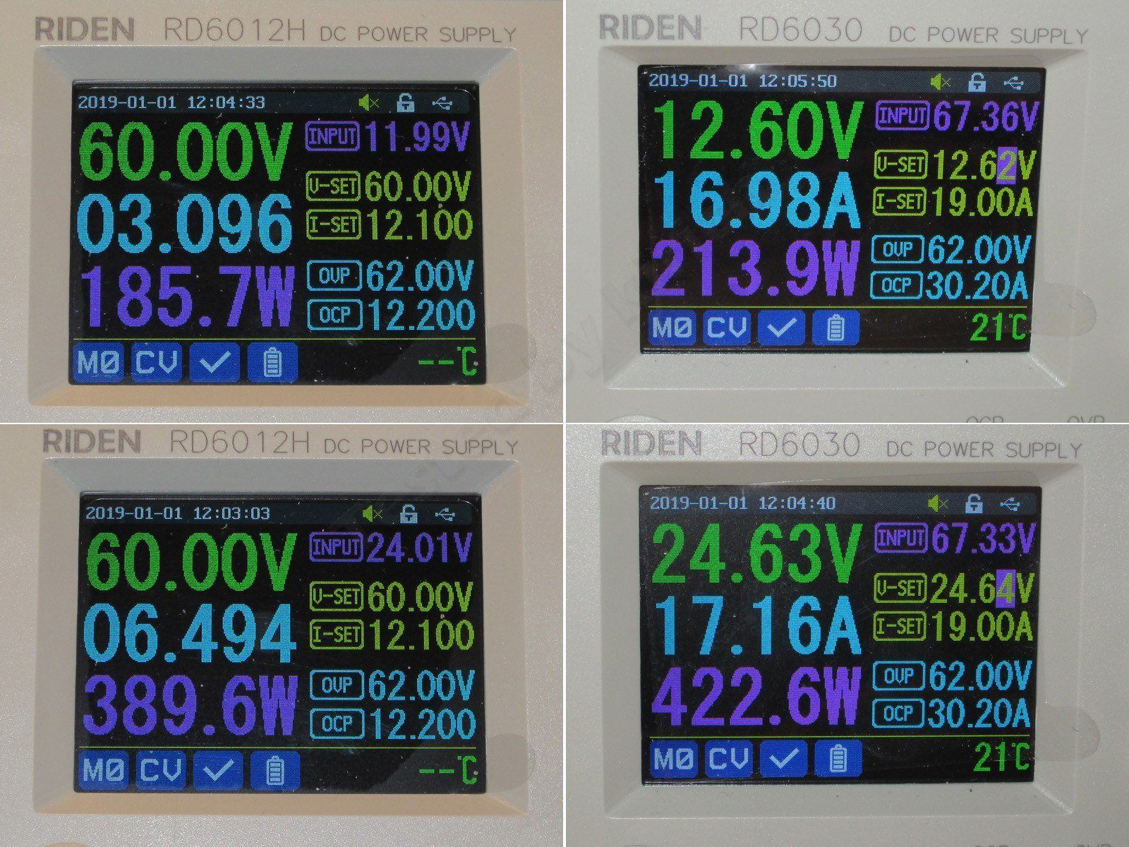
The photos are grouped in pairs: RD6012H on the left, and the RD6030 powering it on the right, where you can see the current draw.
The RD6012H is set to an output voltage of 60 V, with a 12 A load connected, so it's operating close to its maximum.
1, 2, 3. At input voltages of 48, 46, and 43.27 V, everything is fine. The only thing is that the current from the primary power supply was about 17.3 A. In other words, down to about 43–44 V, the RD6012H can deliver around 720 W at a 60 V output.
4. With an input of 41.23 V, the current was already over 18 A, and the output voltage of the RD6012H dropped slightly. In other words, the boost converter had clearly entered current limiting, but nothing shut down.
5, 6. With input voltages of 40.26 and 37.26 V, everything continued to work, but the output voltage dropped to 58.40 and 54.85 V, with input currents of 18.16 and 18.47 A, respectively.
So the converter fully delivers its rated performance and can output 720 W not only at the specified 45 V, but also a little below that—definitely at 44 V, and possibly at 43 V. If you’re willing to take a risk and slightly reduce the shunt value (the 3.5 mΩ one), it should work at an even lower input voltage, but you’ll also need to replace the input fuse.
Now, as in my example, let’s work backwards: we’ll feed 12 and 24 V into the input and see exactly what the converter can deliver at an output of 60 V.
Since the calculations I gave above were for ideal conditions—that is, they didn’t account for the converter’s efficiency—the power figures looked more optimistic. But reality and physics have other ideas.
So, with 12 V in and 60 V out, the maximum is about 3.1 A, or 185 W. The input current is around 17 A, clearly above the rated 16 A, but it works just fine.
With 24 V in, things are much easier: 6.5 A, or 422 W, with just over 17 A at the input.
That’s the maximum you’ll get when powering it from a 12 or 24 V source. Want more? Feed it at least 36 V.
Test six: ripple measurement.
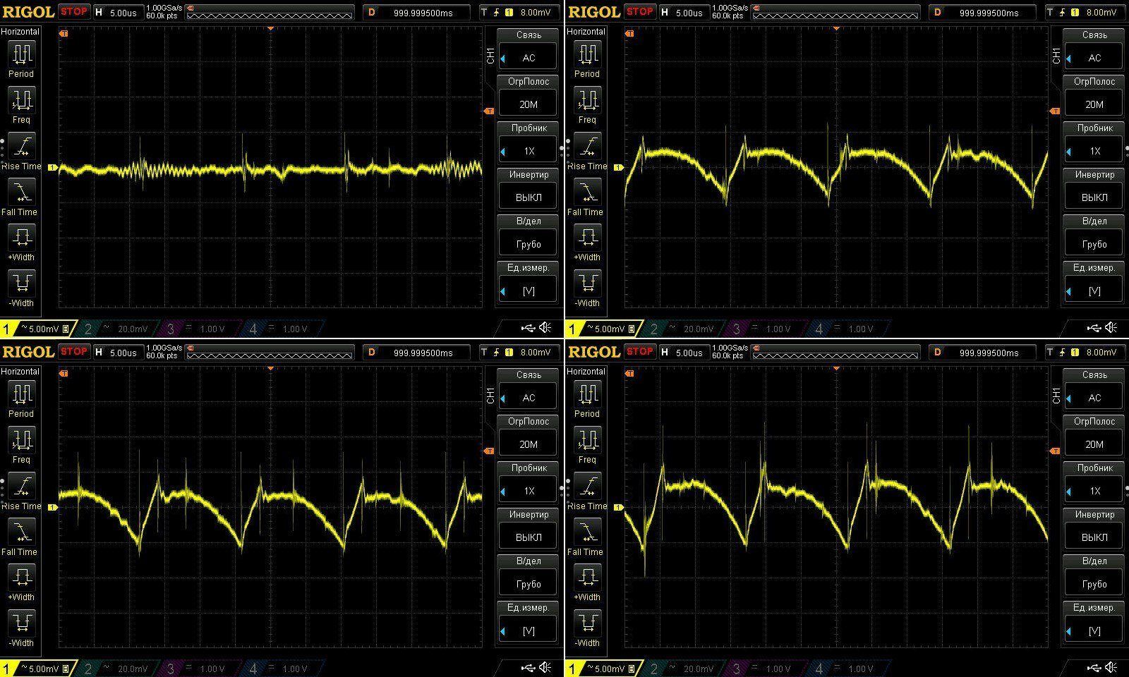
I was very interested in this test, especially because the results were hard to predict. A well-designed boost converter can improve things, while a poorly designed one can make them much worse.
For all the ripple tests, I used a 48 V input, so the boost converter was running close to full power. I also chose 48 V because it’s the most common maximum voltage for branded power supplies.
I’ll start with the output set to 12 V, and check ripple with no load and at currents of 4, 8, and 12 A.
Honestly, the converter really surprised me here. I even checked the oscilloscope cables again, thinking there might simply be no connection.
The point is, even at 12 A, ripple is only 10–15 mV at most. Simply excellent.
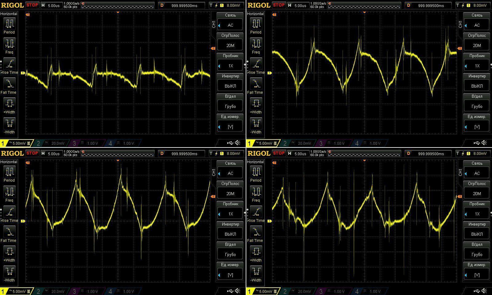
Now let’s change things up a bit: the current is at its maximum of 12 A in every case, but the output voltage varies—5, 25, 36, and 48 V.
As expected, ripple increased, with the highest value at 36 V out. Even then, it was about 20 mV, which looks really good compared with the rated 75 mV.
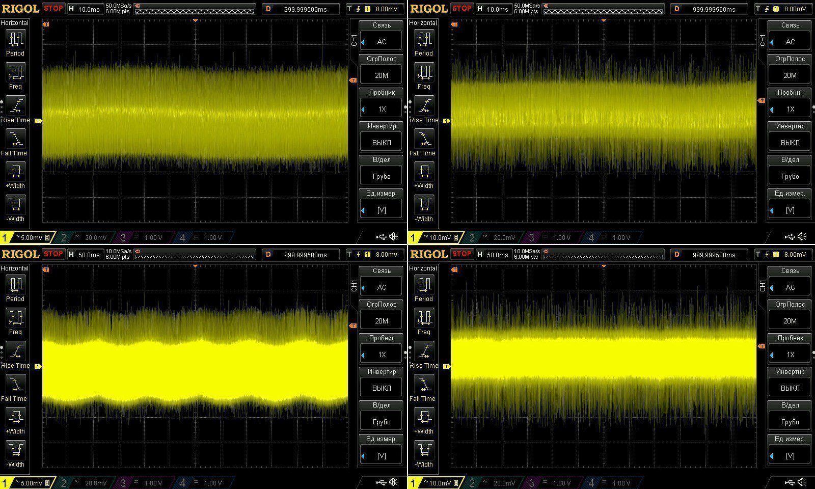
After so many conversion stages (220–70–48–70–output), there’s not much point in checking ripple at 100 Hz, of course, but I took a look out of curiosity and don’t regret it.
The upper screenshots show the results at 12 and 8 V, at maximum current; everything is pretty much as expected. In the lower ones, the timebase is five times slower, revealing small wave-like voltage fluctuations. They’re absolutely nothing to worry about, and mostly show up at lower voltages (12 V on the left, 48 V on the right), so they’re mainly just interesting to observe. There may be some beat frequencies between the two DC-DC converters.
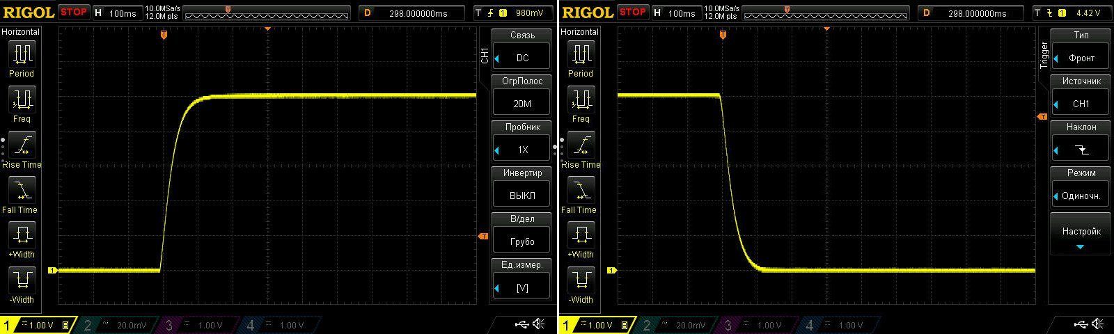
Test seven: transient response.
Applying and removing 5 V at the output: everything looks good, with no issues. I also checked for spikes when connecting and disconnecting power to the converter; no issues there either.
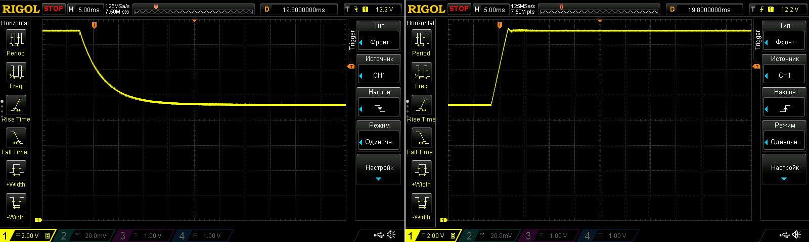
Transition between CV-CC and CC-CV modes: voltage set to 15 V, load current 4.5 A, current limit set to 3 A.
When switching from CC to CV, there’s a small overshoot of around 0.15–0.2 V. I think we can ignore it.
I usually also test connecting and disconnecting the load, but this converter failed that test: I simply couldn’t capture any voltage change on the oscilloscope when connecting a load of around 3.5–4 A. Sure, there must be some change in there somewhere, but it’s so small that it can be ignored. On the other hand, this is not always a good thing either, so it is compensated for by the large output capacitance.
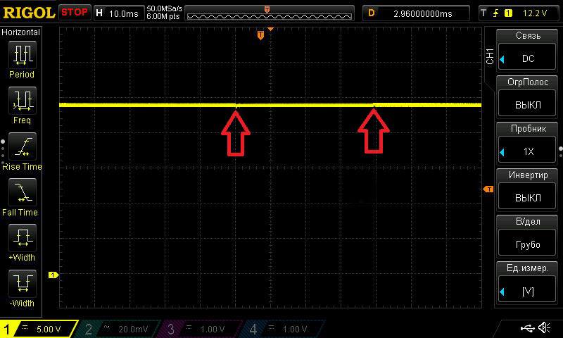
“Soldering iron test”: 24 V output, with a T12 soldering iron connected. Let's look at the spikes when the heater is switched on and off.
They are there, of course—the spikes, I mean—but they're so small that you'd need a microscope to see them :)
Test eight: evaluating the converter's efficiency.
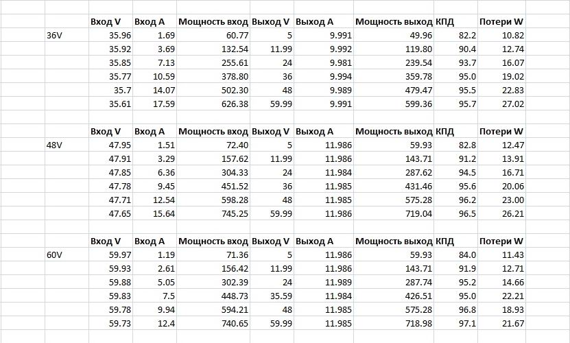
Since this is a “clever” converter, the test was carried out in three stages, with input voltages of 36, 48 and 60 V and output voltages of 5, 12, 24, 36, 48 and 60 V. The load current was 10 A when powered from 36 V, and the full 12 A at 48 and 60 V.
Below is a photo of the test setup with an input voltage of 48 V. I didn't test it with the boost converter switched off, since I didn't see the point: in that mode, it's essentially a standard RD6012, but with slightly lower efficiency due to the voltage drop across the boost converter's disabled diode.
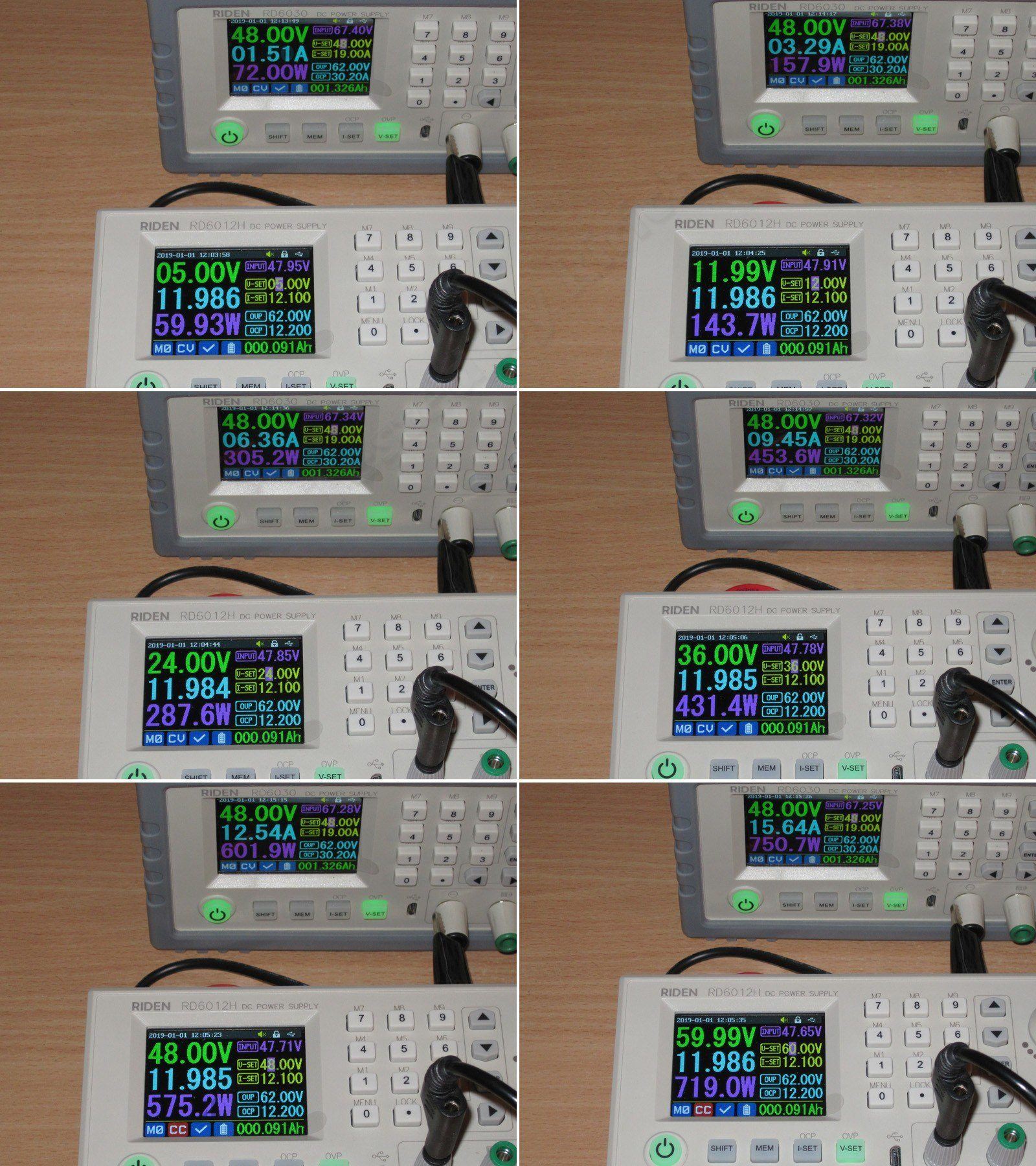
When filling in the table, I entered instantaneous current readings, so there may be some measurement error, but I don't think it's significant.
Below are the results for all the tested modes, both in terms of efficiency and power loss in the converter.
The results look pretty good to me. DPH5005 did well too, though. In the worst-case mode, I measured about 27 W of losses; at maximum output power and 48 V, it was 26 W.
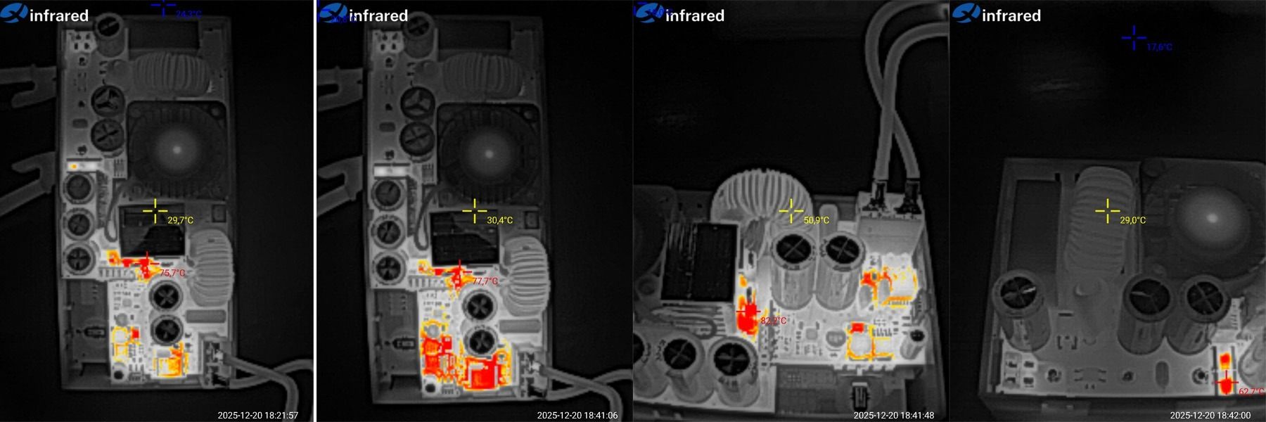
I also checked the converter's thermal performance. For this, I used a setup consisting of an RD6030 and a 1200 W load based on an Atorch controller.
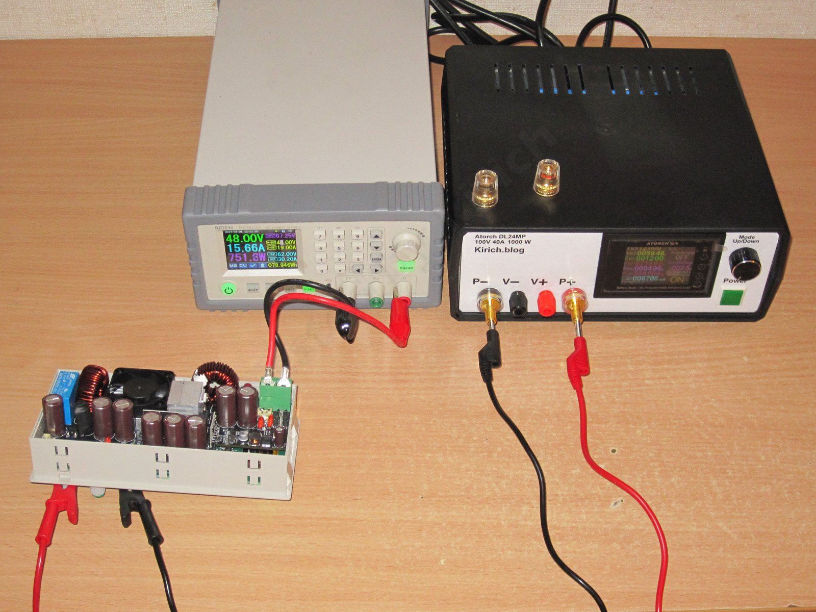
I tried to use a typical, thermally demanding operating mode: 48 V input, 60 V output, and 12 A load current—in other words, close to the maximum across the board.
Of course, input power was over 720 W because of the efficiency losses, while the load received slightly less power due to voltage drop in the wires.
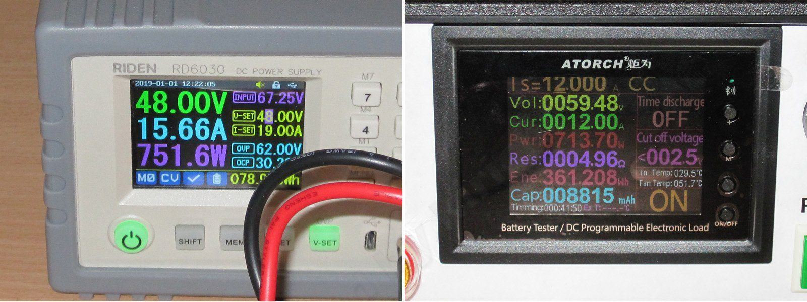
The test ran for a little over 20 minutes. The first photo was taken almost at the start, and the next three after 20 minutes. The converter was lying on the table with the board facing up. Temperatures would of course have been a bit higher inside the case, but I don't think dramatically so.
The hottest component was the boost converter diode, at 82°C. By the way, remember I said it had no thermal paste? I think it wouldn't hurt to add a little, just in case.
Everything else looks good: the boost converter inductor reached 51°C, and the buck converter only 29°C. The shunts did get warm, at 63°C, but everything else stayed cool...
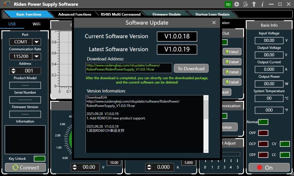
As far as I can tell, the software hasn't really changed. I launched version 18 and it offered to update; the only new feature listed was support for the RD6012H.
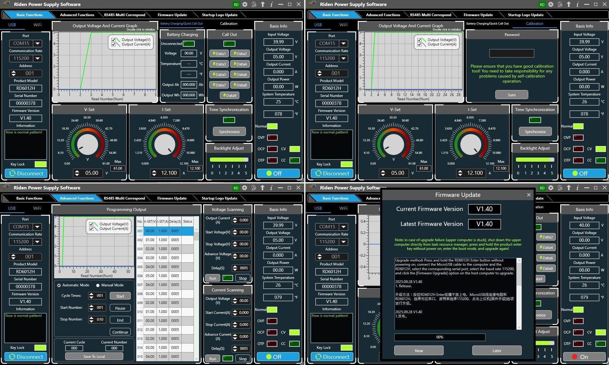
The program is quite feature-rich, although the interface seems clearly overloaded to me.
Calibration is available, but it asks for a password. I didn't check it since everything is fine as it is.
It also supports running a program, but that feature was already there.
The converter firmware is version 1.40, the latest at the moment, and that's about it.
I might check the Wi-Fi connection tomorrow or the day after. There may be some changes, since the module seems to be new. I remember it used to take a lot of fiddling to get it connected.
Conclusions.
To be honest, I was more interested in the 6036 model—that's more important to me personally. And given that the 6018P hybrid model had just come out, it would have made more sense. But the manufacturer has surprised me once again, and I have to say, pleasantly.
Essentially, this is a standard 6012 with a boost DC-DC converter added on. By the way, I didn't measure its output voltage, but based on the DPH5005 model, I can assume it's around 70 V and stays constant.
Adding the converter didn't make the base model any worse, and the output filter noticeably reduced ripple. I also think the lower ripple may be partly due to the board itself now being powered by a regulated voltage—regulated right on the main board, rather than somewhere inside the power supply.
No, I don't think this model will be as popular as the previous ones, but there's no doubt it will find its customers and its niche. That's 100% certain. Partly because of its solid specs, partly because of its distinctive feature—but I really like this model.
The only real downside is the relatively high output capacitance, which makes the converter a little “sluggish.” So if you're testing something like LEDs, be careful.
Otherwise, the specs, efficiency and features really deserve five stars. Now, how do we convince them to develop an electronic load—or, more precisely, a controller module—or, even more precisely, a controller module plus standardized power boards, so users can choose their own cooling system? Maybe we should hold a vote? :) After all, there’s a real gap in the market, and someone else will fill it (Atorch doesn’t count; its software is often a mess), and there’s no guarantee they’ll make anything good.
Well, that’s probably all for today. I hope this was useful, and I’d be very glad to hear your comments and thoughts both on the converter itself and on how you might use it.
$95.45
This page was found when searching for:
riden блок питания 120 v, riden rd6012h vs rd6012h, блоки питания ruideng, riden блок питания повышышай понижай, 1
riden блок питания 120 v, riden rd6012h vs rd6012h, блоки питания ruideng, riden блок питания повышышай понижай, 1
This model is included in the summary table: Comparison of adjustable converters for a bench power supply
The figures from this review are in the measurement database: Converters
Calculate manuallyAll calculators
Discounted products
You may be interested in


Discounted products
Support the project
All the content on the site and the advice are free, but we’d be grateful for your support of the project and the channel!
Comments1
Discuss on the forumThere’s already a forum thread, but no replies yet. Be the first!
Post on the forumOnly registered readers can comment. It takes a minute to sign up, and you can log in with the same account you use on the forum.
Log inRegister
Comments are published in their original language.