
RK6018 converter, the most powerful compact model
$57.49
A reminder: to keep up with new posts on the blog, I recommend following me on Instagram. I'll post notifications about every new article there, and maybe write about something interesting too: link to my account
You can also subscribe to updates and new articles on the Telegram channel - https://t.me/KirichBlog Note that discussions of reviews and articles are enabled on the channel, along with general chat. I recommend it.
As usual, before getting into the review itself, here's a list of products from this company that I've tested.
DPH5005
DPS8005
DPS5020
RD6006
RD6012
RD6018
RD6006P
RD6012P
RD6024
RK6006
Enclosure and power supply for RK6006
RD6030
Silicone case covers
RD 25A cable set
RS485 module with galvanic isolation for connecting RD60xx series converters
RD6018P
RD6012H
RK6012
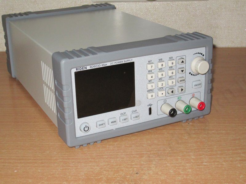
RD6030-max
RK6006H
This will be a fairly simple, short review, partly because this converter is actually much simpler than the previous one, and partly because it's essentially just a higher-power version of the RK6012.
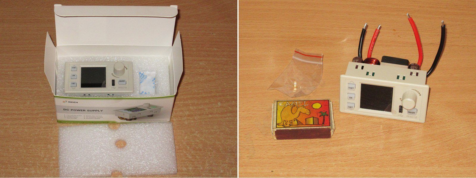
Accordingly, the packaging, dimensions, number of buttons, their functions, and so on are all exactly the same.
The package includes only a 25 A fuse. The more expensive bundle also includes a Bluetooth module and an external temperature sensor.
Specifications
Model: RK6018/RK6018-BT
Input voltage range: 12-70.00V
Output voltage range: 0-60.00V
Output current range: 0-18.00A
Output power range: 0-1080W
Input voltage measurement resolution: 0.01V
Output voltage setting measurement resolution: 0.01V
Output current setting measurement resolution: 0.01A
Input voltage measurement accuracy: ±(1%+5 digits)
Output voltage accuracy: ±(0.3%+3 digits)
Output current accuracy:±(0.5%+2 digits)
Output ripple typical:100mV VPP①
Working temperature range: -10℃~40℃
External sensor temperature detection range:-10℃~100℃/0℉~200℉
External sensor temperature detection accuracy:±3℃/±6℉
Constant voltage mode response time: 2ms(0.1A-5A Load)
Constant voltage mode load regulation: ≤0.5% or ≤100mV(higher one)
Constant current mode load regulation: ≤0.5% or ≤15mA(higher one)
Capacity measurement range: 0-9999.99Ah
Energy measurement range: 0-9999.99Wh
Capacity and energy statistical error: ±2%
Buck working mode: (input voltage÷1.1)-1②
Over temperature protection: System temperature>85℃
Screen brightness setting: 0-5(6 level in total)
Screen: 1.54 inch 240*240 color HD display
Cooling fan start condition:Output current>6A or System temperature>55℃, high speed when over 70℃
Cooling fan shut down condition:Output current<5.9A and System temperature<45℃, fan runs at low speed when lower than 56℃
Weight(with package):About 0.17kg
Product dimension: 79*43*61mm
Support USB communication: yes
Support Bluetooth communication: Only RK6018-BT supports
①:Ripple measurement method: noise and ripple are measured at X1 range, AC coupling, 20MHz of bandwidth on your oscilloscope, with a 0.1uF parallel capacitor at the output terminals
②for example: input voltage is 24V,the max output voltage is 20.8V
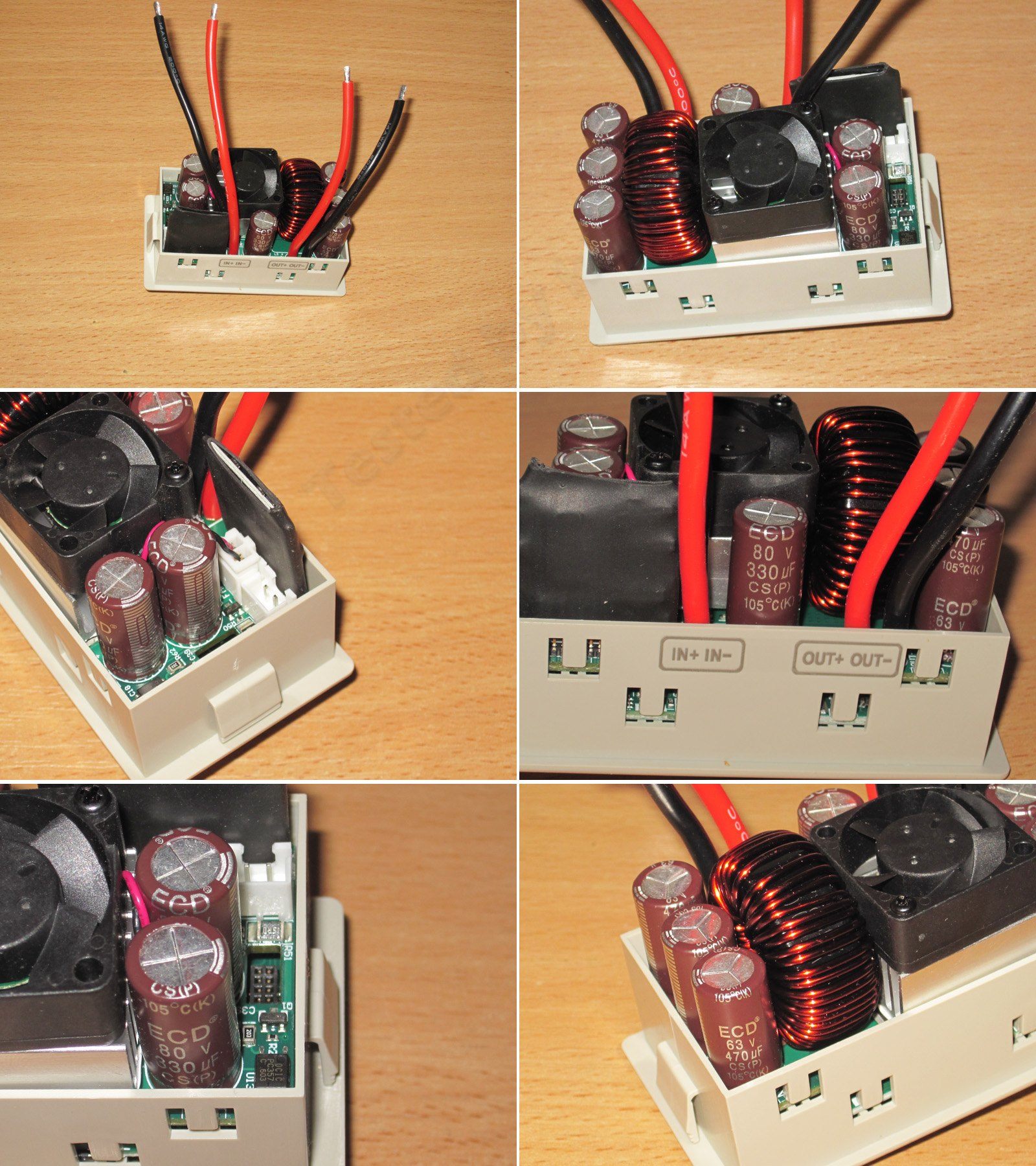
Perhaps the only significant difference is that there are no terminals for connections. The manufacturer simply brought out wires, with different lengths for the input and output. They're 14 AWG.
The input has three 330µF 80 V capacitors; the output also has three, but they're 470µF 63 V. Of course, it would have been better to use 80 V capacitors on the output too, but I think the required capacitance was greater than 990 µF, and 470 µF capacitors rated for 80 V simply wouldn't fit.
The board has a connector for an external temperature sensor. Like the BT module, it comes with the second package option; I have the basic version. There is also a connector nearby for installing the BT module.
The control submodule is covered in heat-shrink tubing, so there's no point opening it up. It's almost certainly their standard TL594.
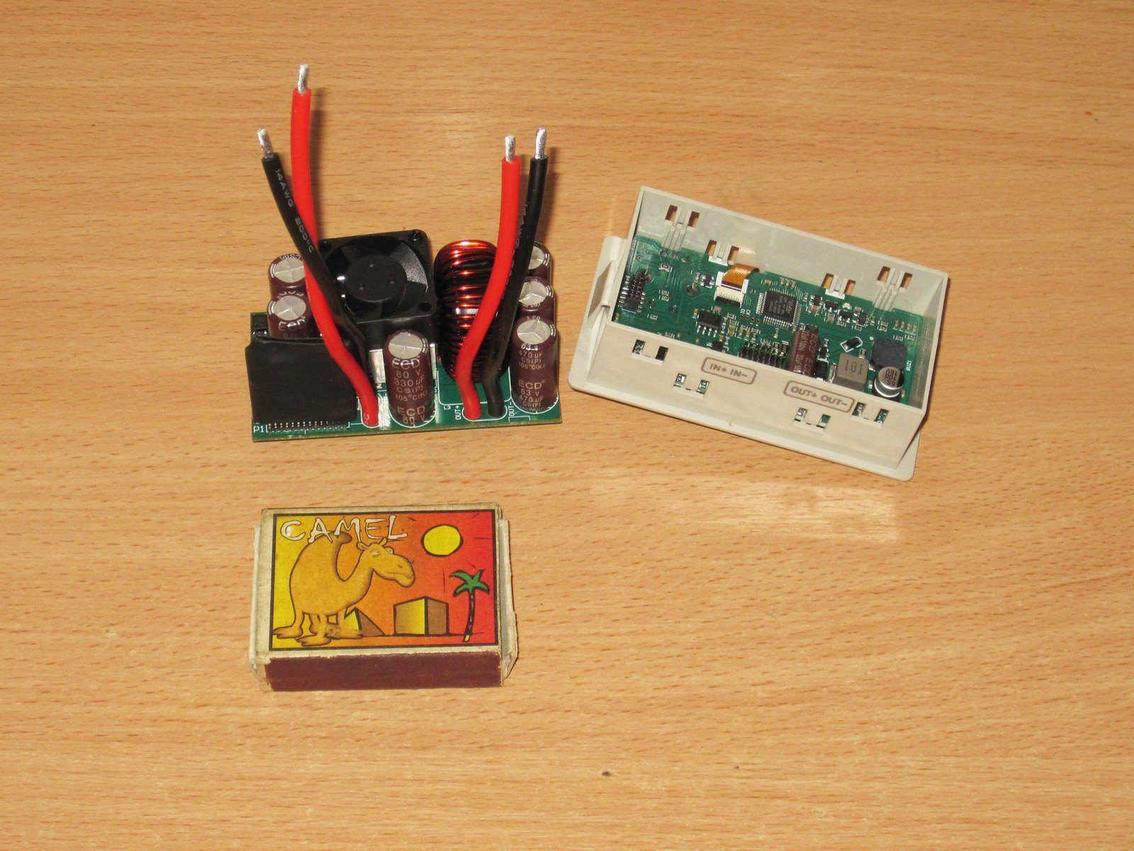
The module is very easy to take apart: just release a few clips and remove the board.
There's not much of interest here: one of the fuses, a few small components, and an inductor to reduce output ripple.
The controller module looks exactly like the one in the previous models.
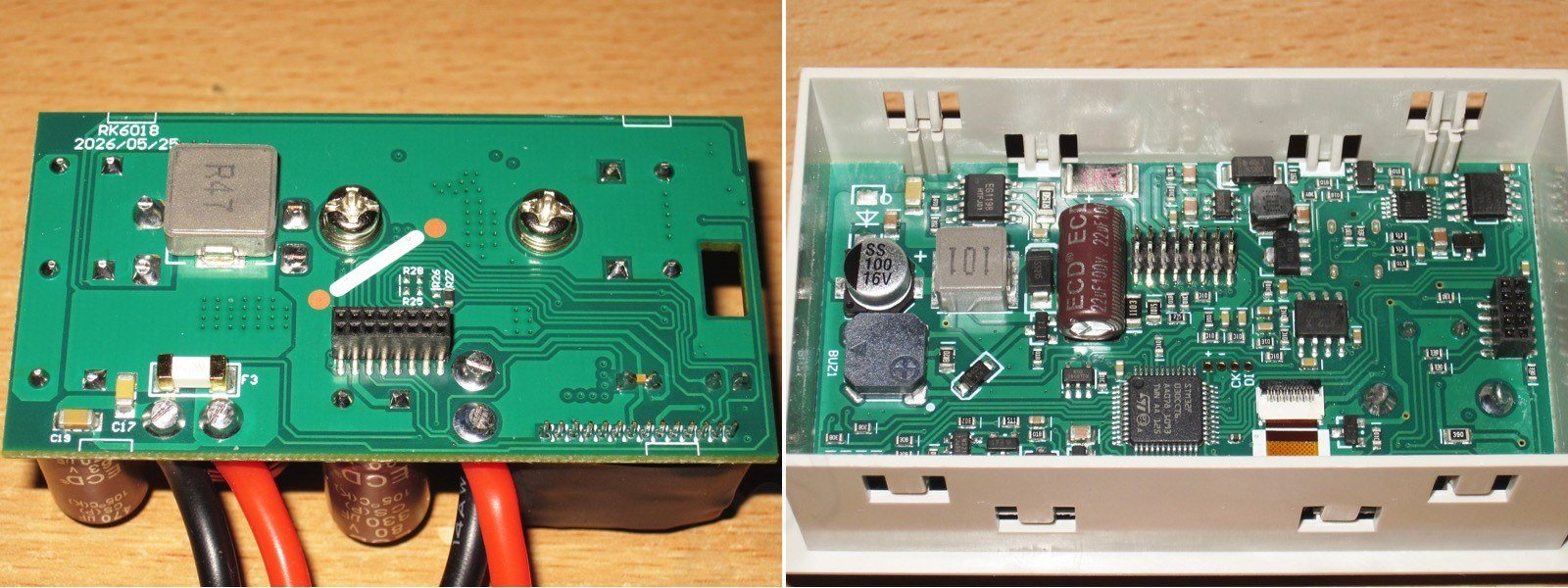
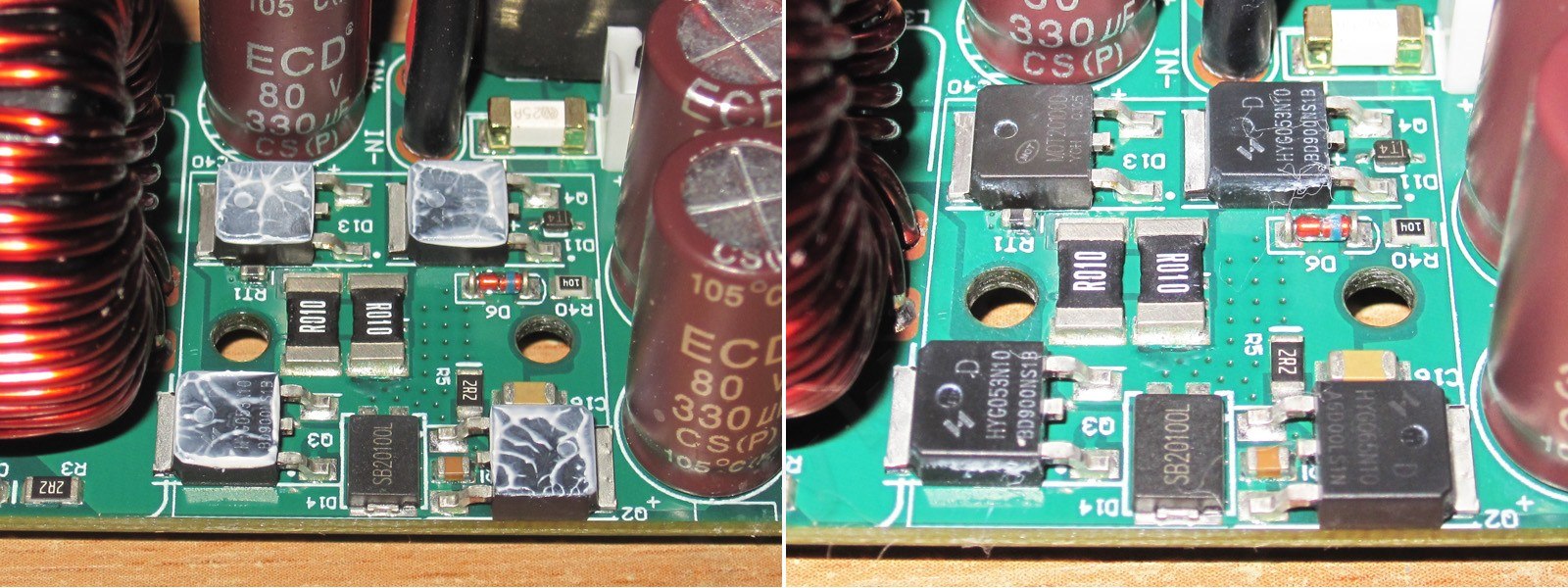
The power components are under the heatsink. It's worth noting that heat is dissipated not only from the semiconductors, but also from the shunts—a very sensible idea.
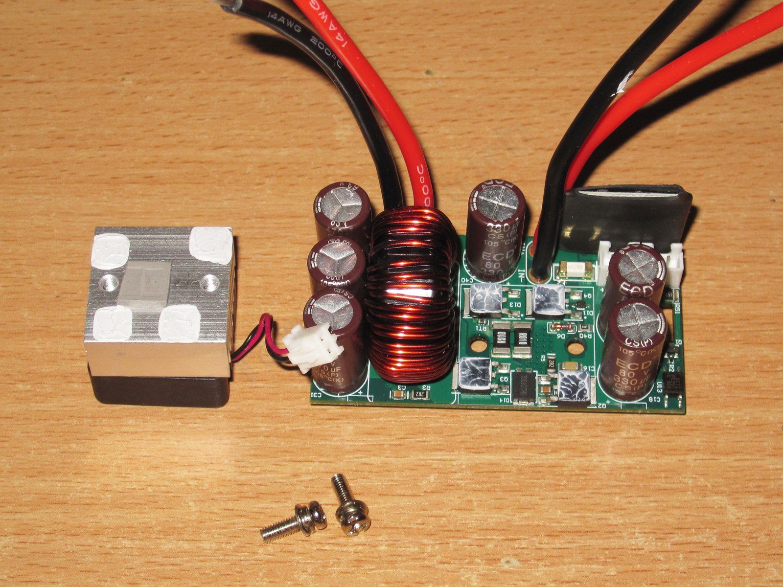
There are also three transistors and a diode assembly under the heatsink, pressed against it. There's another diode like the one in the 6006H, but I don't know what it does.
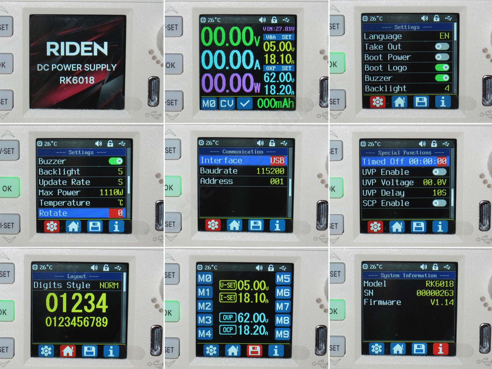
When switched on, the unit displays its logo, then the converter enters normal operating mode.
The menu is also much the same as on the previous 6006H. The power limit is higher, and the option to disable the step-up converter is gone.
I forgot to mention last time that the newer versions let you set an operating limit. I also wanted to say a few words about the UVP function.
People often ask whether there's reverse-current protection when charging batteries. No, that feature is available on the RD60xx, but the point is that UVP can be extremely useful.
The main danger isn't the reverse current itself, but the fact that if input power is lost, your converter keeps drawing power from the output. The output itself remains active, so when input power returns, there's a large current surge that can damage the power supply.
BUT! If you set the cutoff threshold slightly below your power supply's voltage, then if the mains power goes out, the converter will deactivate the output, and nothing will burn out when power is restored.
For example, if your power supply outputs 68 V, set it to 60–65 V and sleep easy.
The tests will be the usual ones for Riden reviews; it's genuinely hard to come up with anything new here.
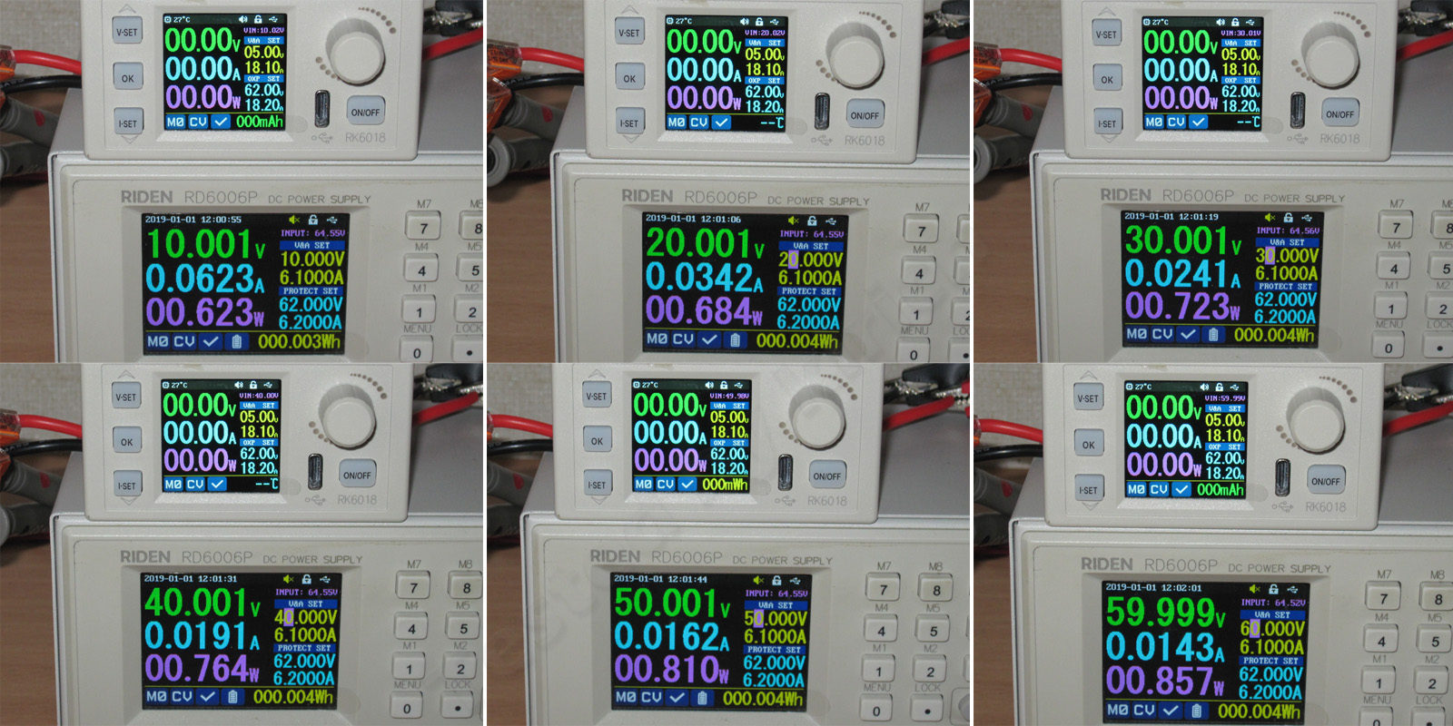
Test 1: input voltage measurement accuracy.
It reads 0.2 V high at the lower values and 0.5 V low at the higher ones—not a big deal.
Test 2: voltage setting and measurement accuracy.
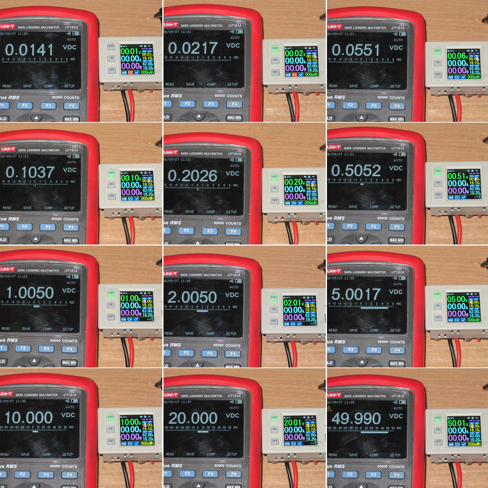
As usual, I checked the 1-2-5 series from 0.01 V to 50 V.
Overall, it's quite accurate. There's a slight positive error at low values, but everything is fine beyond that. Riden has never had accuracy problems anyway.
Test 3: current setting and measurement accuracy.
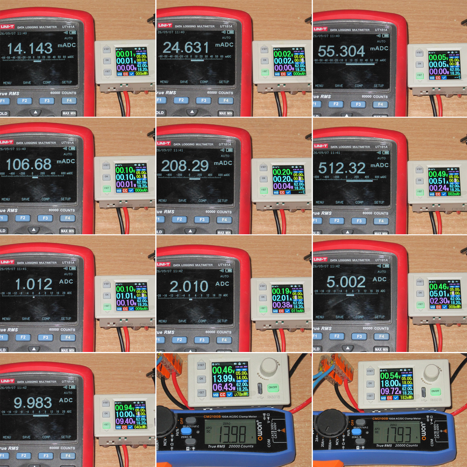
There's some overreading up to about 2 A, then underreading above 10 A. As usual, the lowest values are the worst: you won't be able to set exactly 20 or 50 mA.
The last two results are somewhat questionable, since at that point the accuracy of the clamp meter becomes a concern.
Test 4: output voltage versus load.
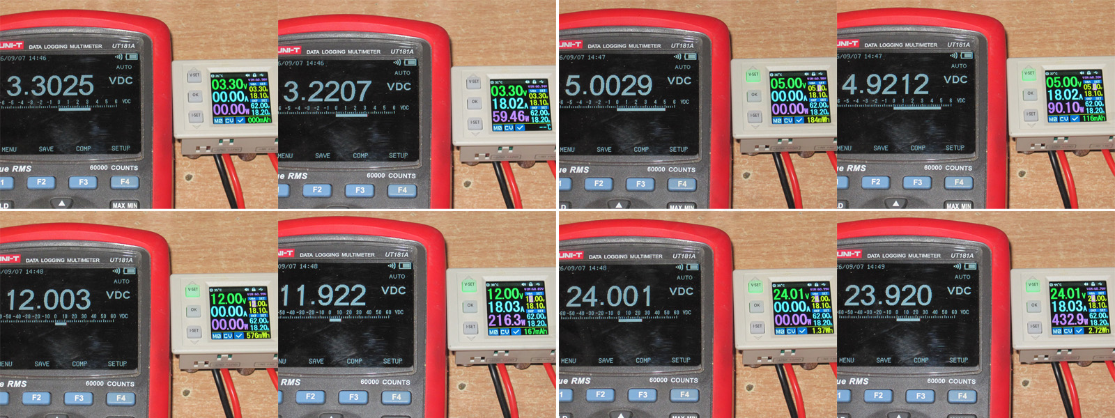
Two destabilizing factors affect the accuracy here: connecting the unit with wires and the fairly high current of 18 A.
In the end, at 3.3, 5, 12, and 24 V, I measured a difference of about 80 mV between no load and maximum current.
Test 5: minimum input/output voltage difference.
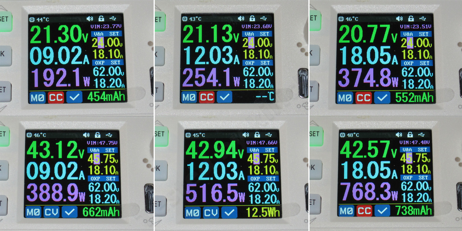
I tested this at two input voltages, 24 and 8 V, and three current levels: 9, 12, and 18 A.
At 24 V and maximum current, I got about 3.2 V; at 48 V, 4.9 V, respectively. These figures should be taken into account when choosing a power supply. To get the full 61 V at the output, it’s best to use a 68–70 V power supply.
Test six: ripple level.
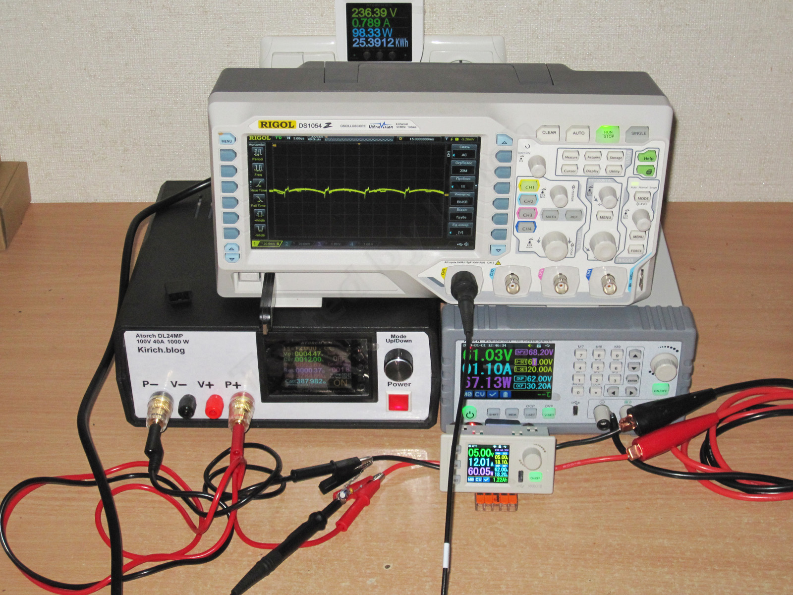
For this test, I used an RD6030 power supply, an Atorch-based electronic load, and an oscilloscope.
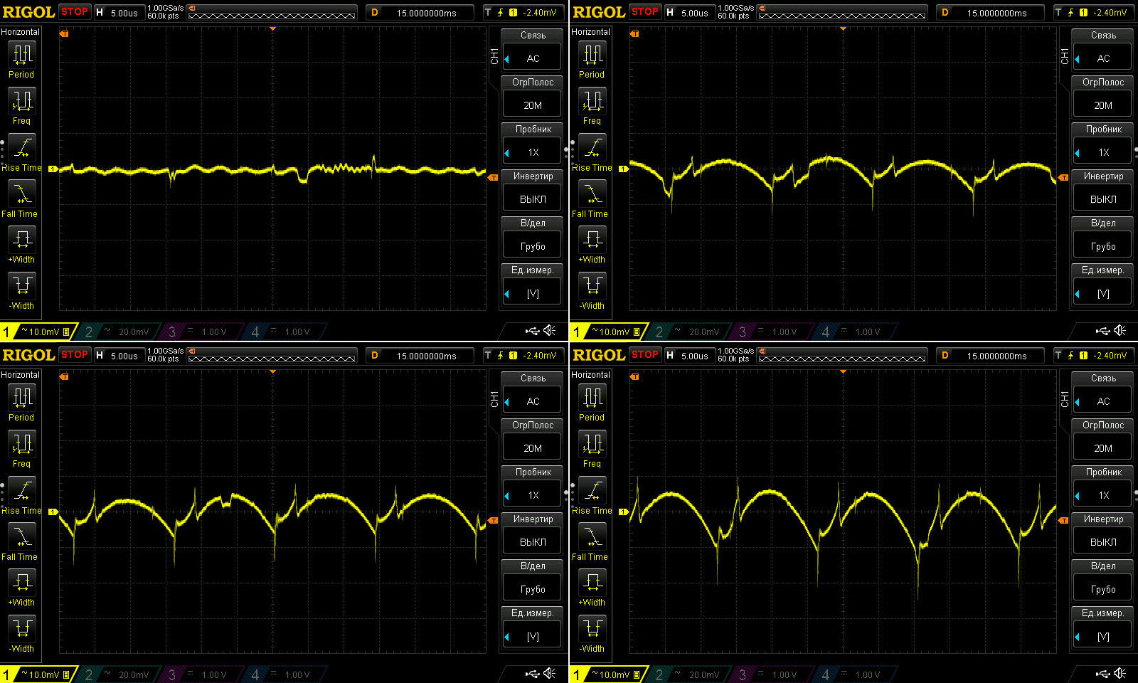
As usual, the first test was run with 61 V at the input and 12 V at the output. Here are the results with no load and at currents of 6, 12, and 18 A.
The manufacturer specifies 100 mV peak-to-peak. In this test, I measured a maximum of 30 mV, though I think it helped that the oscilloscope was connected after the wires. In any case, that’s how this converter is intended to be used.
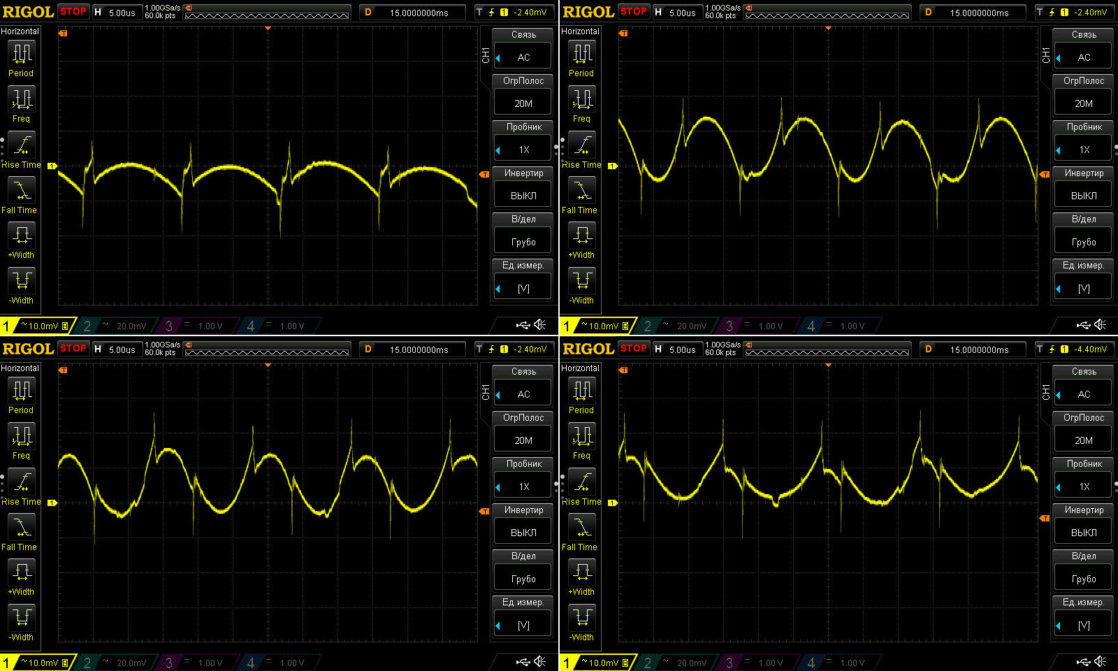
Now for the results at the maximum current of 18 A and output voltages of 5, 25, 36, and 48 V.
Nothing much changed: ripple went from 30 mV to 35 mV :)
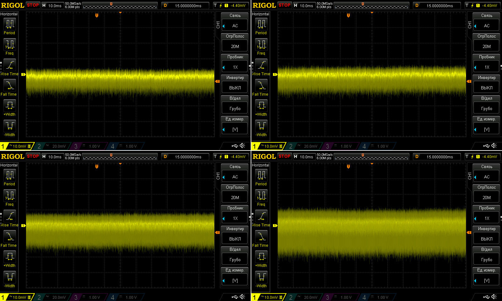
And here’s the ripple at a slower timebase, with 12 V output and currents of 3, 6, 12, and 18 A.
Again, no surprises. Still, as a precaution, I’d recommend putting a ferrite ring on the wires. It won’t take up much space, and it may reduce interference.
Test seven: transient response.
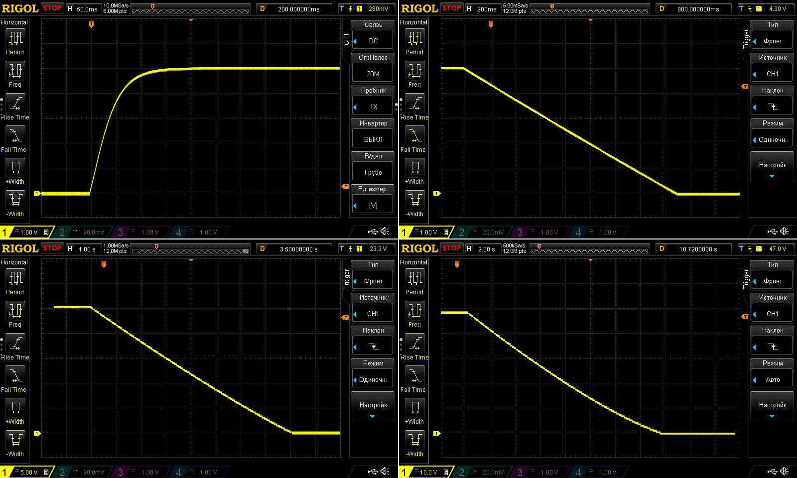
First, here’s what the output voltage looks like when 5 V is switched on and off, with the output set to 5, 25, and 48 V.
What can I say? The low power of the discharge circuit and the large output capacitor bank affect the results. Switching on looks good, but switching off takes a very long time: at 48 V, it takes about 15 seconds!
As far as I know, a current regulator is often used for this kind of task instead of a regular resistor, to avoid excessive heating across the whole range while achieving the fastest possible discharge. I’d guess that this converter series has a less powerful discharge circuit than the RD60xx series, which is why the capacitors discharge slowly.
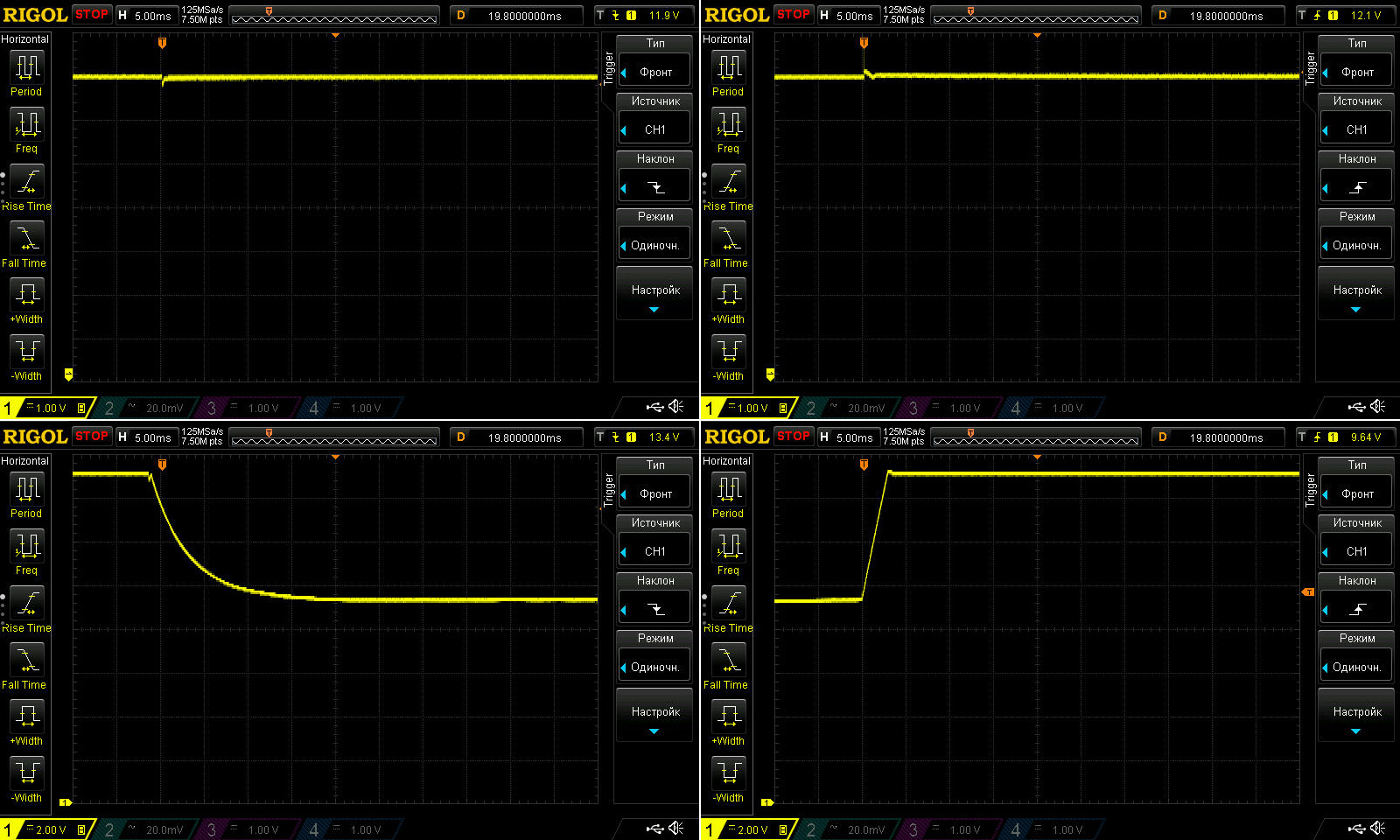
1, 2. Response to connecting/disconnecting a load. The output was set to 12 V, with a 30 Ω resistor connected continuously and a 3.3 Ω resistor connected in parallel with it (and then disconnected). This tests the response to a current step from 0.4 to 4 A and from 4 to 0.4 A.
3, 4. Transition from CV to CC mode and back. Voltage: 14 V; load current: 4.5 A; current limit set to 3 A.
It performed well in all modes. Brief spikes and dips of around 0.2 V shouldn’t be a problem.
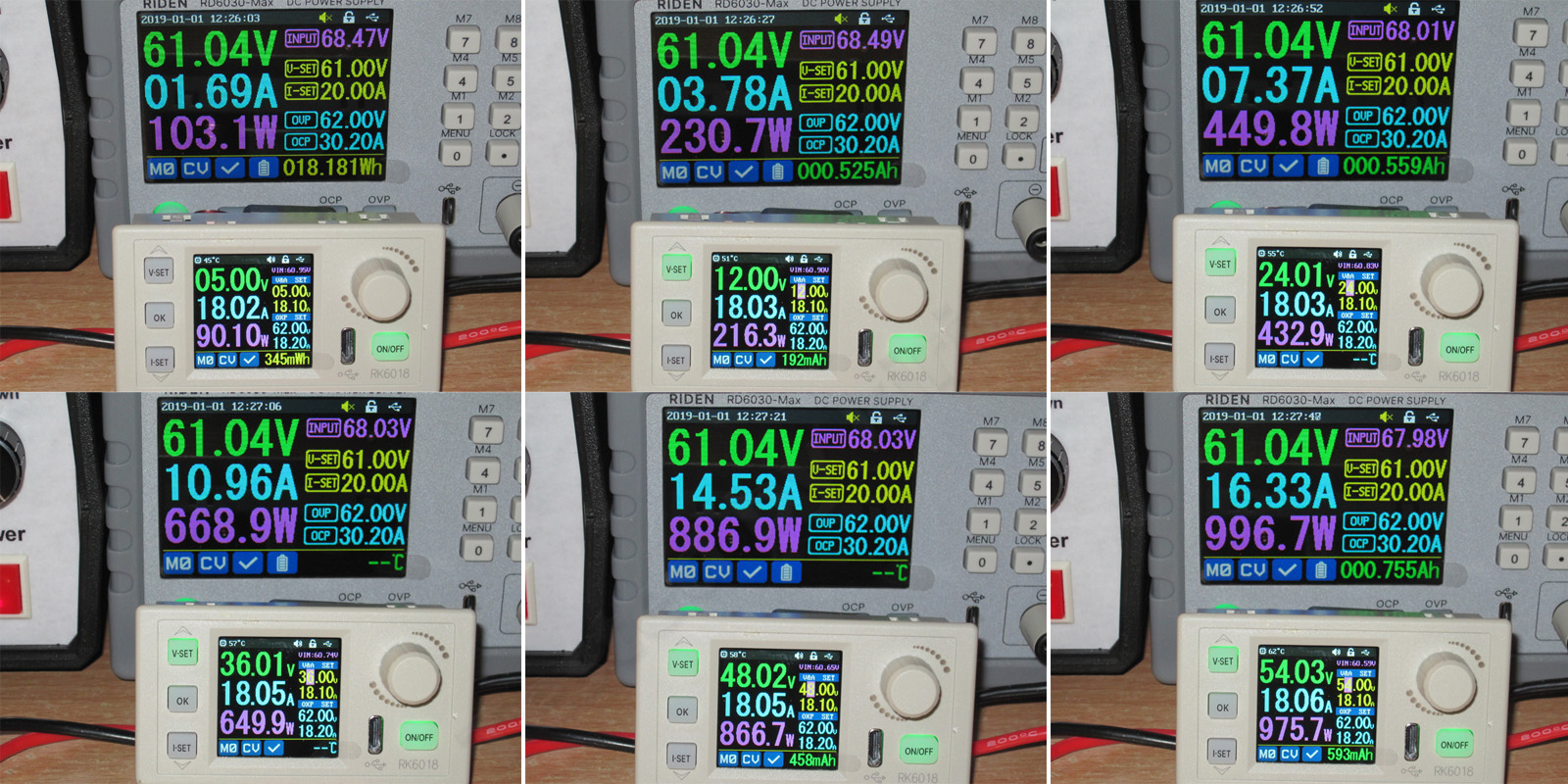
Test eight: efficiency and power losses.
The input was around 60–61 V, and the load current was at its maximum throughout. Output voltages were 5, 12, 24, 36, 48, and 54 V. Even with 61 V at the input, I couldn’t get 55 V at the output, but I don’t think that difference is significant.
The results:
5 V — 87.3% — 12.9 W
12 V — 93.7% — 13.9 W
24 V — 96.5% — 15.4 W
36 V — 97.6% — 15.8 W
48 V — 98.3% — 14.5 W
54 V — 98.6% — 13.7 W
Efficiency is very high, while the greatest power losses occurred with the output voltage near 36 V. By the way, I think the losses (and therefore the heat) were even higher on the 6006H version.
Test nine: thermal performance.
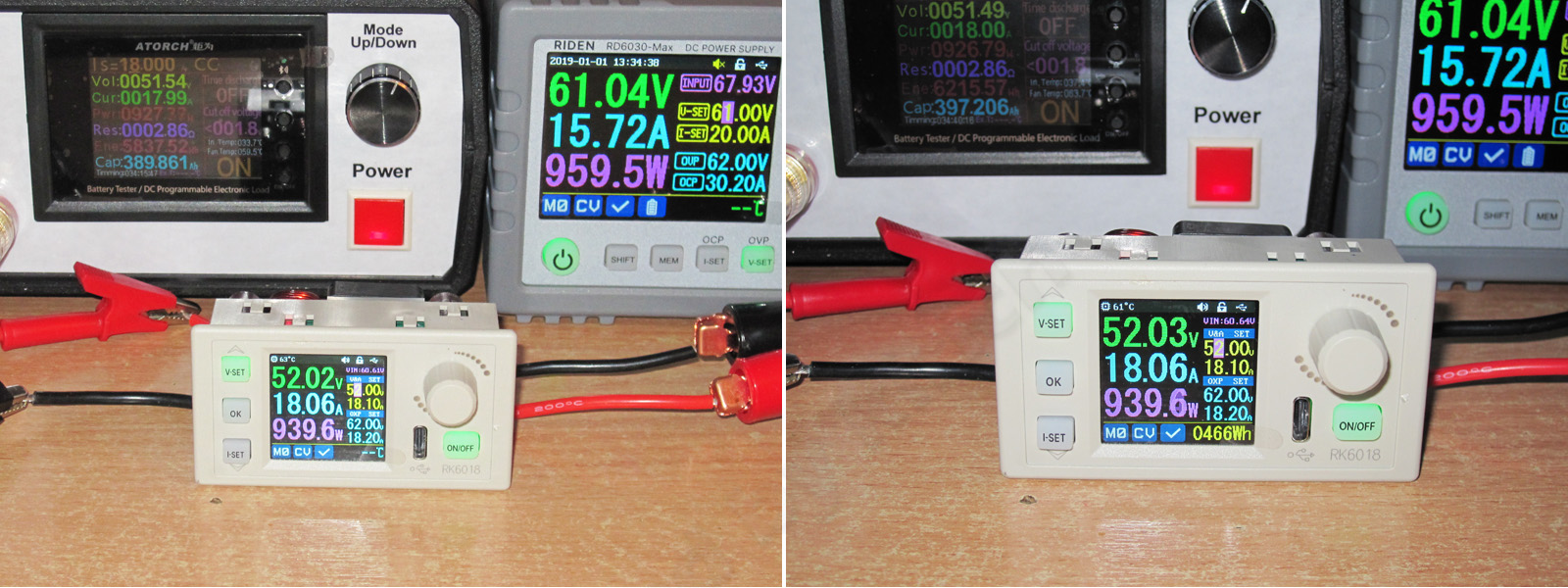
Here I powered the converter from the same 61 V source. The load current was 18 A, and the output voltage was 52 V, giving the converter an output power of about 940 W. Of course, that's not the claimed 1080 W, but I didn't really want to rig up two power supplies. And judging by the efficiency measurements, the heat generated might have been even lower.
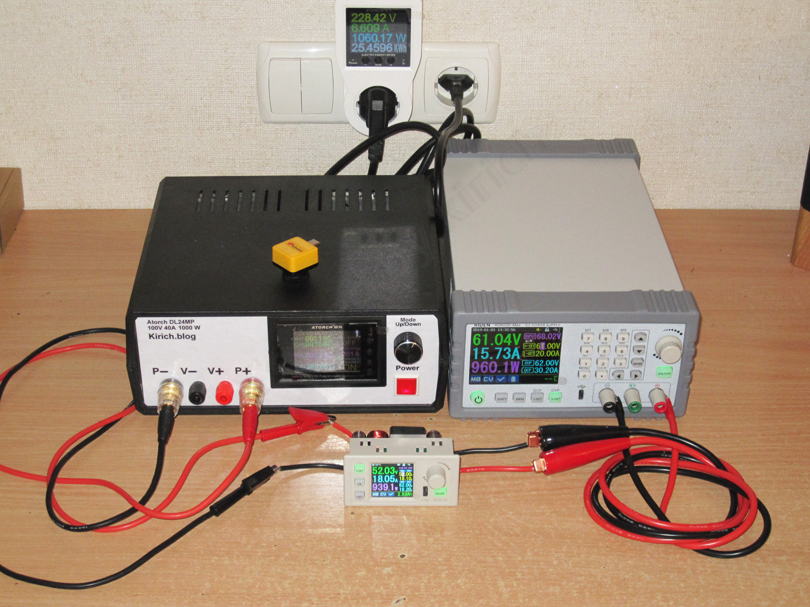
The start and end of the test. Curiously, according to the built-in temperature sensor, the reading was 63 at the start and 61 degrees at the end. Very strange.
Thermal image before the test. Since its own power consumption is lower than the 6006H's, the idle temperatures were lower too.
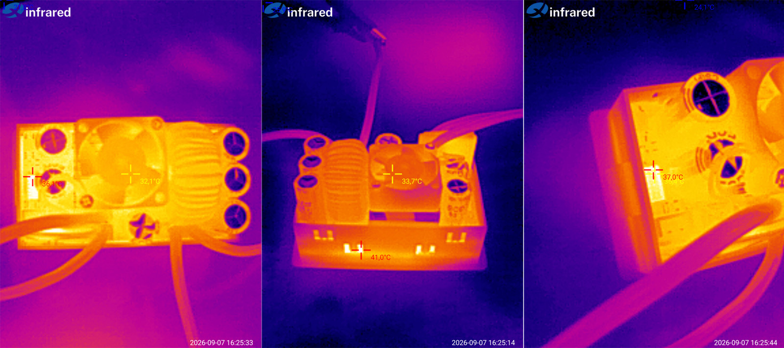
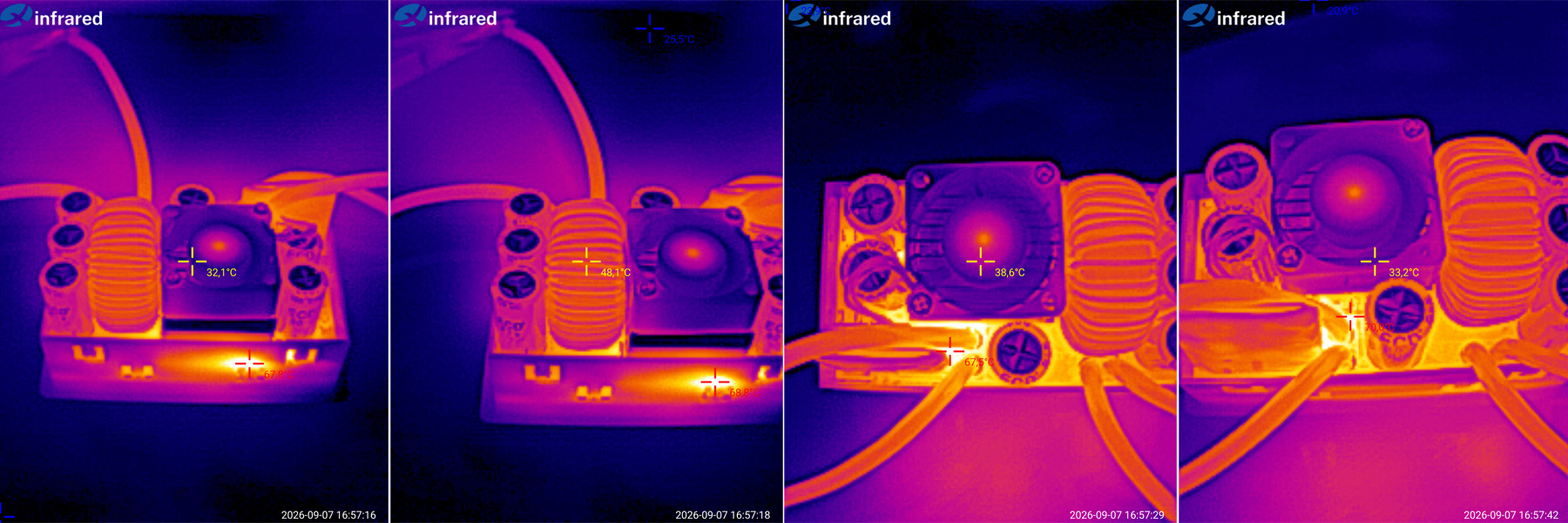
And after the run. For obvious reasons, I couldn't measure the temperature of the semiconductors, so I checked everything else.
The highest recorded temperature was around 70 degrees in the area between the heatsink and the input wires. The power inductor was around 48–49 degrees, and everything else was cooler still.
I came across a complaint online that the converter had “melted” for one user at maximum power. I can imagine it was either a defective unit or the fan had stopped, although in the latter case the thermal protection should have kicked in.
In any case, here are all the results: the losses are genuinely low, and the temperatures are low too.
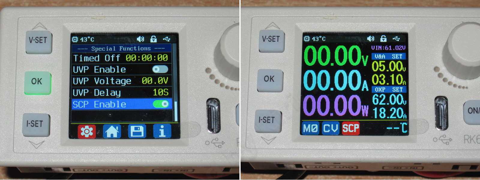
In my RK6006H review, I mentioned the SCP function—that is, short-circuit protection—and planned to capture some oscilloscope traces, but I never got around to it.
No, nothing burned out. As they say, either the skis or me—I hope it's the skis...
I went into the menu, enabled the corresponding mode, and started experimenting. It turned out that the function does basically work: if there's a short circuit or an overload, the converter doesn't switch to CC mode; it shuts off the output instead.
But, as they say, there's a catch: the function is slow. First I set the output to 5 V and the current to 4.1 A, then tried briefly touching the wires together, but nothing shut off. I did notice something, though.
If you keep the wires shorted, the output current rises gradually, reaching about 4 A after roughly 0.5–0.7 seconds. If you don't disconnect the wires by then, the output shuts off.
So, on the one hand, there is short-circuit protection, and it prevents the current from exceeding the set limit for an extended period. On the other hand, it behaves rather oddly. Of course, the surge current from the capacitors is still there, and there's no way around that in principle. To eliminate the capacitor inrush, you'd need at least to disconnect the output with a separate transistor, rather than simply shutting down the converter.
Conclusions
The only thing I can really fault is the odd SCP function. Otherwise, it's genuinely good: great efficiency, low losses, and very good ripple performance.
Ease of use is still lacking, as usual, but as I wrote, there's only so much you can do with four buttons. Otherwise, it's a very appealing converter.
Of course, someone will say, “So you need a 1 kW power supply for it too.” Well, basically, yes—though actually, not necessarily. There are plenty of applications that don't need high power but do need high current and sometimes voltages up to 60 V. With the included 360 W power supply, you'll get 18 A at up to about 20–22 V; at 40–44 V, it'll be more like 9–10 A; and at the maximum 60 V, the most you can expect is 6 A.
In short, I don't have any major complaints about the converter itself. I'm not considering its range of applications here—different people have different needs.
That's all for today. I hope you found it useful.
I missed the sale: literally yesterday it was $40, and today it's already $57. Anyway, if you need one, keep an eye out for deals.
$57.49
This model is included in the summary table: Comparison of adjustable converters for a bench power supply
The figures from this review are in the measurement database: Converters
Calculate manuallyAll calculators
Discounted products
You may be interested in


Discounted products
Support the project
All the content on the site and the advice are free, but we’d be grateful for your support of the project and the channel!
Comments3
Discuss on the forumHave a question or some experience to share? Discuss the article with the author and readers: the forum is a convenient place to share schematics and photos.
Go to the forumOnly registered readers can comment. It takes a minute to sign up, and you can log in with the same account you use on the forum.
Log inRegister
Comments are published in their original language.