
More power supplies, this time 48 V
While I was thinking about this article, I kept remembering an old and very well-known film with the unassuming title "Three Plus Two".
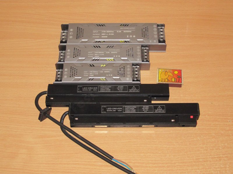
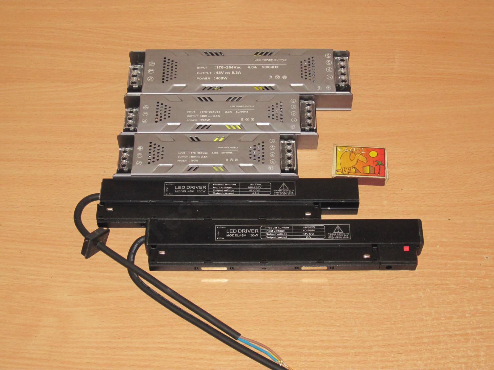
Why? Because there are five power supplies: three of one type and two of another. They’re also split into two pairs—100 and 200 W—and one on its own at 400 W.
So today I’m reviewing two 100 W power supplies, two 200 W units, and one 400 W unit. I think it’ll be interesting :)
A reminder: to keep up with new posts on the blog, I recommend following me on Instagram, where I’ll post notifications about new articles and maybe just write about something interesting — link to account
You can also subscribe to updates and new articles on the Telegram channel — https://t.me/KirichBlog Just a note: discussion of reviews and articles is enabled on the channel, and you can also just chat. I recommend it.
48 V power supplies are quite common, but I didn’t know they were used in lighting systems. I’m used to seeing 12 or 24 V. The advantage of a higher voltage is lower current at the same power, which means less voltage drop along the same strip. Of course, there are drawbacks too—there always are.
Similar power supplies are also sometimes used to power simple bench power supplies, so perhaps this review will be useful for that as well. Anyway, let’s get started.
As I said, I was sent five power supplies, all rated for 48 V, with power ratings of 100, 200, and 400 W—or at least that’s what the specs say. Three have a conventional form factor, or at least one I’m familiar with, while the other two are quite unusual.
I’ll start with the conventional ones and save the two unusual ones for dessert :)
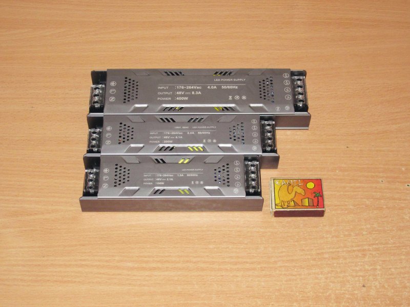
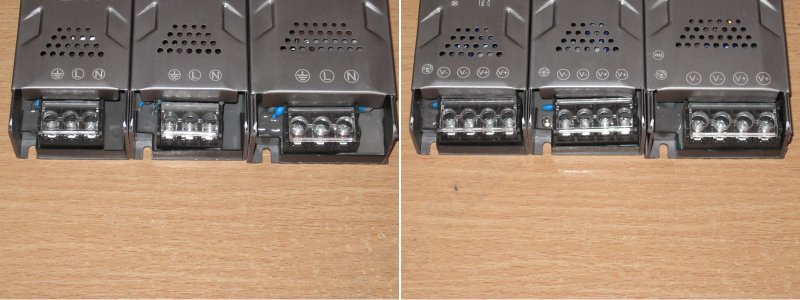
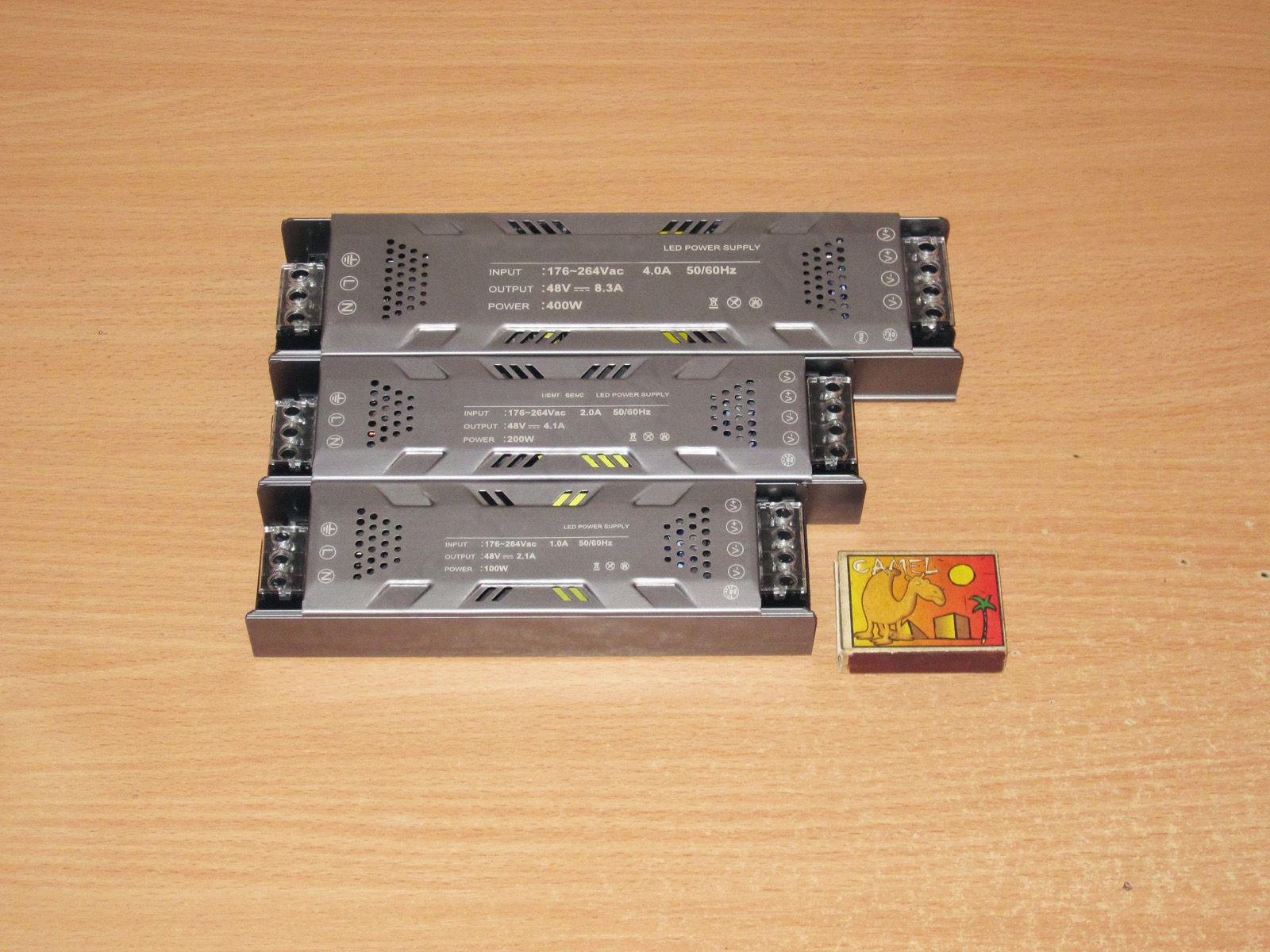
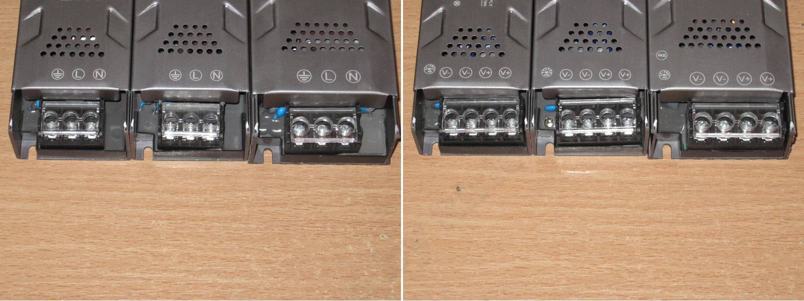
All three power supplies have the same connection layout: three terminals on the mains side and four on the output side. The terminal blocks have covers, but there are holes in the covers, so you can clamp the wires without even opening them. Convenient.
The first one is the 100 W model: 48 V, 2.1 A.
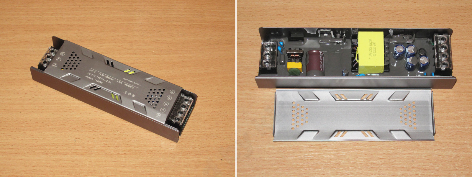
Dimensions: 175 × 48 × 29 mm
And to get ahead of myself, this whole series looks very familiar. I’ll have to dig through my test results and articles, because I’ve definitely come across it before—maybe in a slightly different case and for a different voltage, but that’s not really important.
The circuit board is coated with protective compound, making these power supplies more resistant to high humidity. But keep in mind that they’re definitely not sealed. In any case, the compound serves several purposes at once: moisture protection, improved electrical safety, and slightly better heat dissipation.
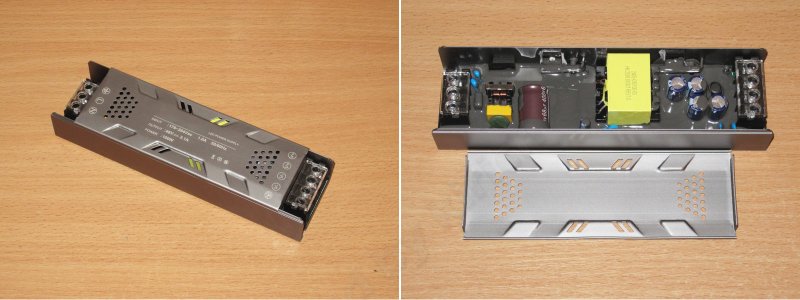
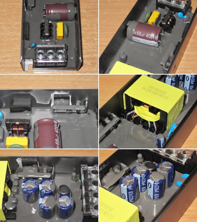
1. The input has an almost complete filter. There’s no varistor, but I think the more important thing is that there’s a thermistor. You can also see the Y capacitors for suppressing interference, which suggests they didn’t cut too many corners.
2. The input capacitor is 68 µF, which is a bit small, at least for 100 W. But keep in mind that the specified input range is narrow: 176–264 V. Even so, the capacitance is right on the edge.
To explain why I mentioned the input voltage range: the lower the input voltage, the more input capacitance is needed. Power supplies can be designed for a narrow range, something like 85–130 V or 198–255 V, or a wide range, 85–255 V. The exact values can vary, but the important point is that if a power supply is designed for a wide range and doesn’t have an active power factor correction circuit or a 115/230 V switch, it has a harder time operating at low voltage. Most of the strain falls on the bridge rectifier, input capacitor, and converter transistor.
Okay, I’ve probably overloaded you with details. In short, for the specified range and power, the input capacitor is usually 82–100 µF; for a wide input range, the capacitance is increased by about 1.5 times.
3. The bridge rectifier and high-voltage transistor: the bridge rectifier is just sitting there, while the transistor is pressed against the heatsink, with thermal paste applied. Good.
4. A nice-looking transformer. I couldn’t resist taking a photo. At least some of the windings use stranded wire, which is also a plus.
5. The output diode assembly is also pressed against the case, and there’s thermal paste here too. The LED covered in compound made me smile—I didn’t even notice it at first. Camouflage level 80 :)
6. The output has four 220 µF, 63 V capacitors, along with an inductor to reduce ripple. As always, I’d like to see more capacitance: "pills for greed, and lots of them" :) In my opinion, 330 µF would look better, but this is fine too.
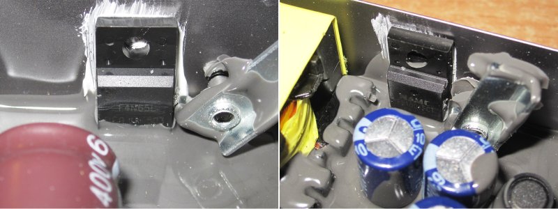
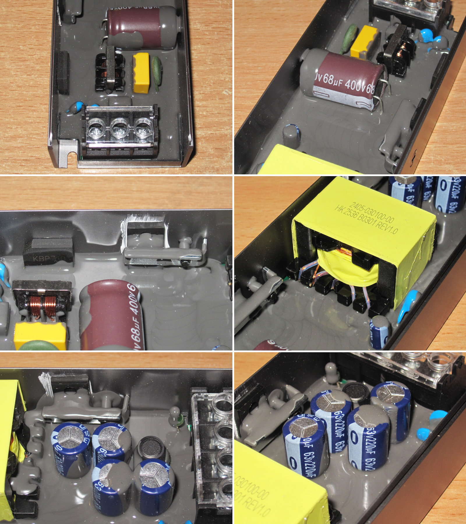
After testing, I got around to checking the power components in all the power supplies.
1. A 4 A, 650 V transistor—perfectly adequate.
2. The output diode assembly is an ER1004FCT, rated for 400 V and 10 A. It’s a ultrafast diode, of course, since Schottky diodes are generally not used at these voltages. But it has plenty of headroom for this power supply.
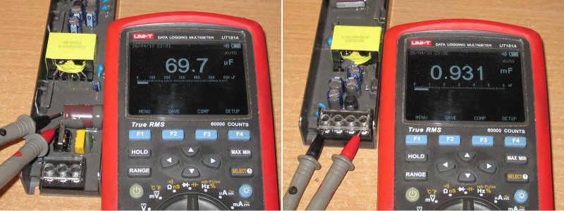
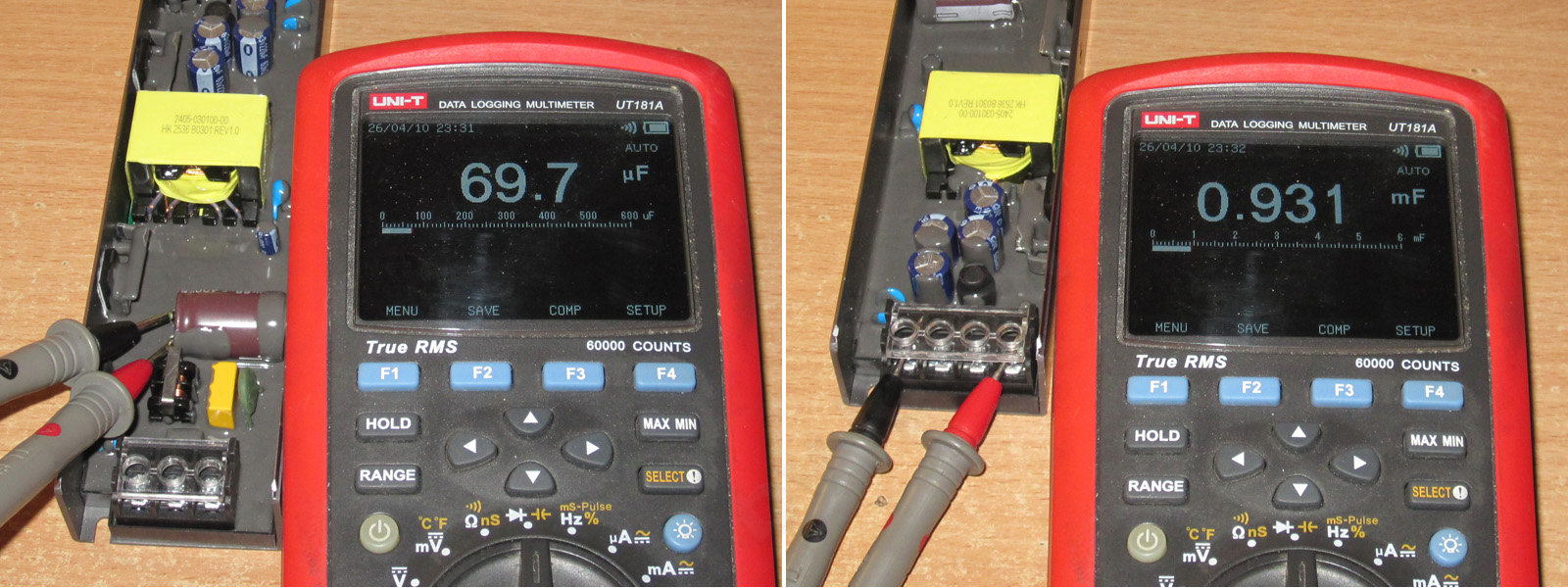
1. The measured input capacitor capacitance came to almost 70 µF. Damn, I think this is the first time the actual input capacitor capacitance has exceeded the rated value.
2. The total output capacitance is 930 µF, all good.
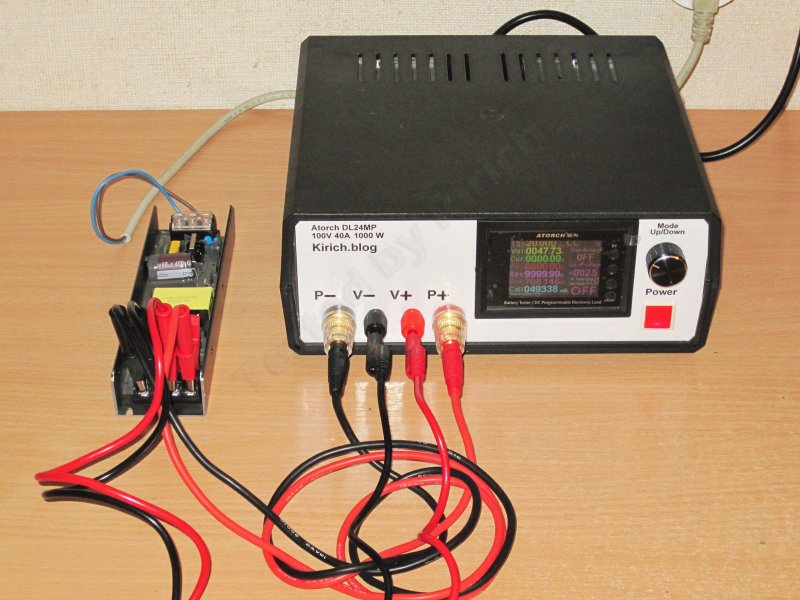
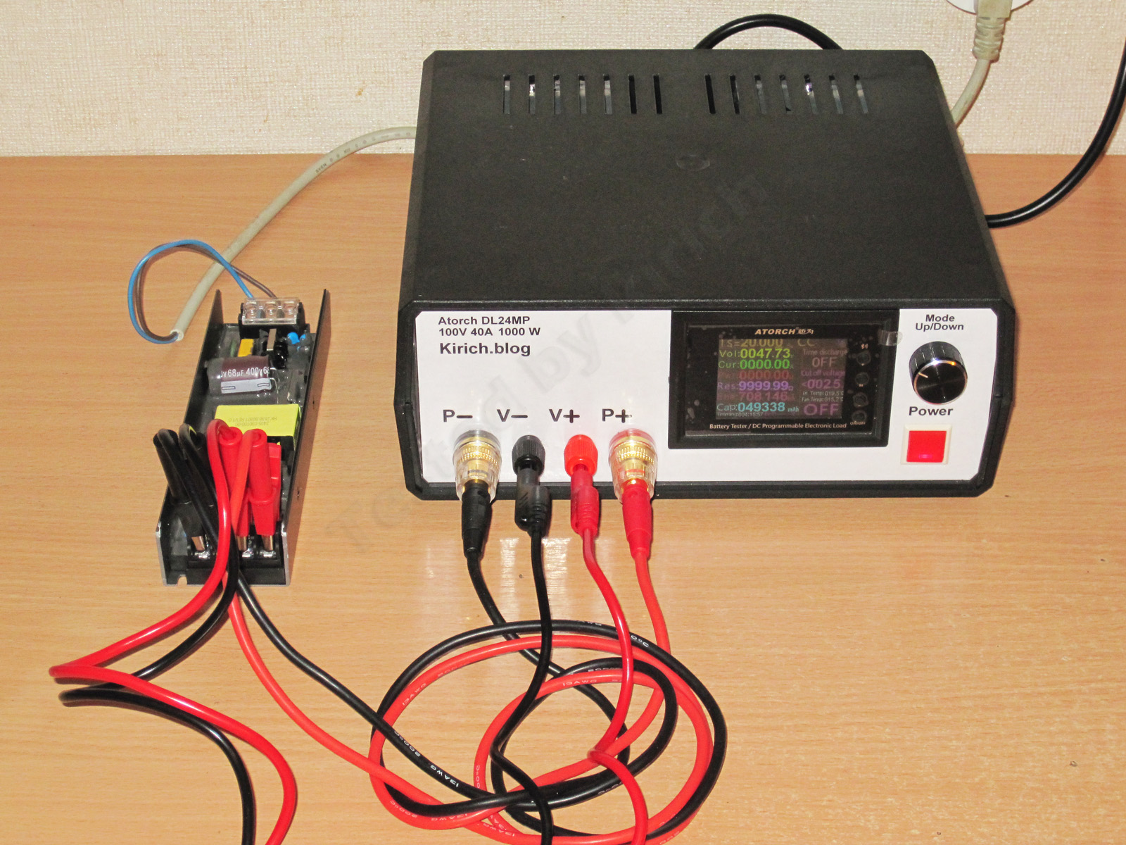
For all the tests, I used a 1200 W electronic load based on the Atorch DL24MP controller. Someone might ask: why not the trendy new BW600?
Yes, I’ve almost completely switched to building 1200 W versions with the BW600, but for testing power supplies, the old 24MP is definitely a better fit. It may be noticeably behind the new model in hardware and software, but that one is more geared toward battery testing. It’s a shame Atorch discontinued it, but I still have a small stock :)
Even though the voltage is high here, I still used a four-wire connection. Why not, especially since it was convenient.
I messed up a bit with the photo of the overload protection test, and it wasn’t easy to do anyway, because it turned out that the power supply not only has a clear threshold-based protection, but also shuts down at 1.7 A. So in practice, its output power is around 77 W. By the way, it’s worth noting that at this power level, the input capacitor’s capacitance is quite sufficient for normal operation.
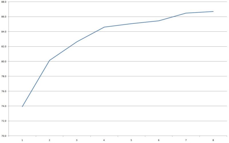
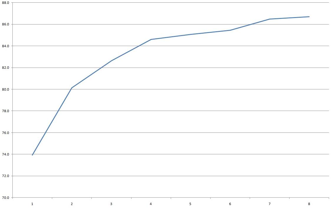
Efficiency was measured from 0.2 to 1.6 A in 0.2 A increments and came out to 85–86%, which is pretty good. I’ll also point out that the graph shows efficiency rising toward the end of the test. This indirectly suggests that the power supply is being held back a little and could actually deliver more.
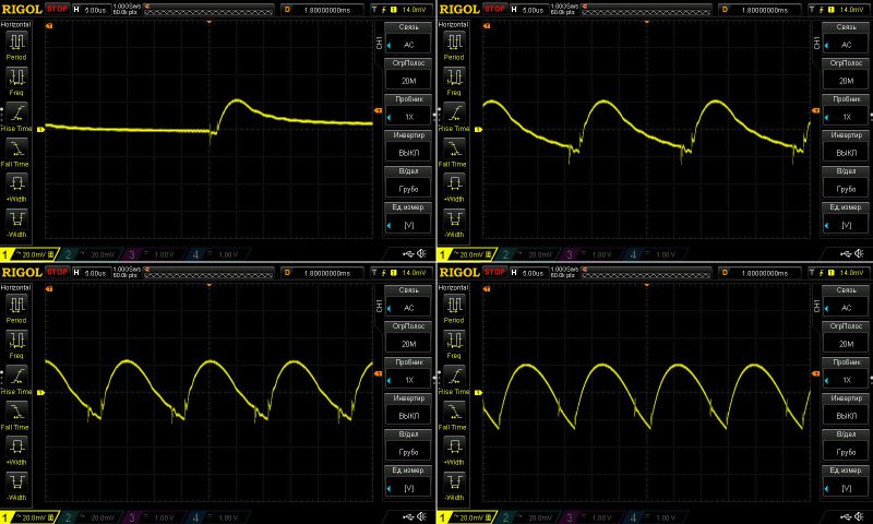
As for ripple, at least at high frequencies it looks really good: even at 1.6 A, it’s only 50 mV, with no spikes. Considering the 48 V output, that’s a very pleasing result. The low ripple is almost entirely thanks to the output inductor, and I’m glad they didn’t skimp on it.
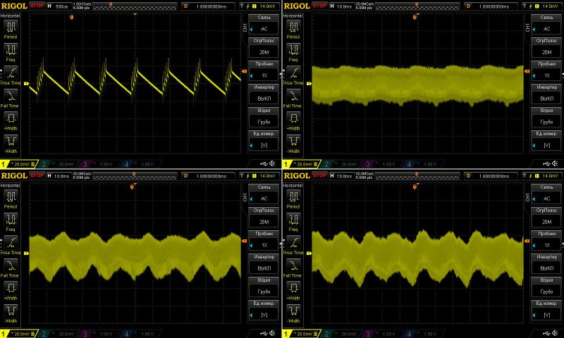
Ripple was measured with no load and at currents of 0.5, 1, and 1.5 A.
At low frequencies, I think it’s also excellent. The 100 Hz component is slightly visible, but at such a low level that you can simply ignore it.
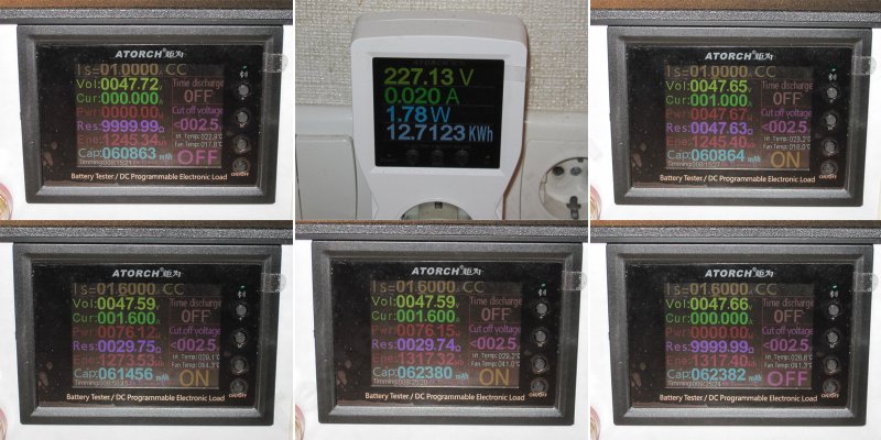
Load test.
1, 2. With no load, the output is 47.72 V, and power consumption is quite high at almost 2 W. That’s a lot. Apparently the manufacturer disabled the “green mode”; I can’t think of another explanation, although another possibility is that it uses some ancient controller, which seems much less likely.
3. Load current: 1 A
4, 5. Load current: 1.6 A, before and after warm-up
6. Warmed-up power supply with no load.
So what do we see? The output voltage drops by about 70 mV as the load increases, and also drops by 60 mV as the unit warms up. For a 48 V supply, that’s excellent.
Temperature rise at 1 A and 1.6 A. I’ll only comment on the second case, since the first is laughably easy for this power supply.
In short: transformer, 64 °C; transistor, 52 °C; diode assembly, 53 °C.
This brought to mind a line from a movie: “You could work that thing to death.” Exactly. The temperatures aren’t just low; it feels like this power supply is running at about 50% of its rated power. The thermal headroom is enormous. For example, the transformer reached 64 °C in a room at 20 °C, so its temperature rise was 44 °C. Even with an ambient temperature of 50 °C, the transformer would still be at a reasonable temperature, not to mention the other components.
Second model: 48 V, 4.1 A, 200 W.
Dimensions: 193 × 48 × 29 mm. The only difference from the previous model is the length; this one is a couple of centimeters longer. Otherwise, they’re twins.
The topology is also unchanged; the manufacturer simply scaled up the previous model. Speaking of topology, both models use a flyback circuit. It can usually operate over a wide input voltage range, but since the input capacitor capacitance is often undersized, I recommend sticking to the 176–264 V range printed on the case.
1. The input has the same filter as the 100 W model, and it’s essentially faultless as well. The bridge rectifier is made up of two diodes connected in parallel.
2. There are now two 47 µF capacitors. I think that’s too little for the rated 200 W output, but let’s see what the tests show.
3. There’s one transistor, also pressed against the case with thermal paste.
4. But there are two output diode assemblies, while the filter capacitors are unchanged. In other words, they’ve simply added one diode assembly to the output stage.
The transformer is just as nice-looking, although for some reason they used a very low-profile one here. There wasn’t much point, but it’s not a bad thing either.
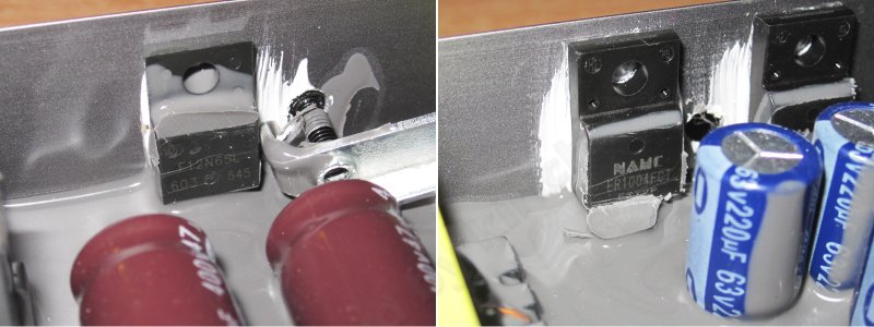
1. A high-voltage transistor rated for 12 A and 650 V—not bad at all. I assume they beefed up the control circuit too, but I can't see what's under the potting compound.
2. The diode assemblies are the same as in the previous model, so the headroom is just as good.
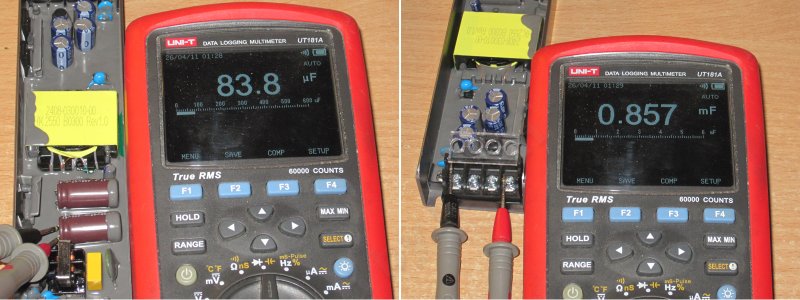
1. Well, everything is back to normal here. The input capacitors are rated at 47 µF each, so two should give 94 µF. In reality, it's about 84 µF, which is clearly too little for 200 W.
2. What's interesting is that the output uses the same capacitors as the 100 W model, from the same manufacturer and with the same capacitance. But there the total was 930 µF, while here it's about 860 µF. I can imagine that some of the power supply circuits affect the results, but I won't claim that for sure. In any case, in my opinion, that's a bit low for an output current of 4 A with this power supply topology.
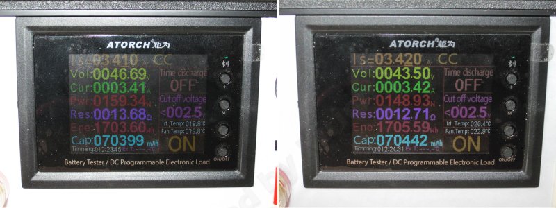
The protection trip-point test revealed two things. First, the protection has a fixed threshold: increase the current just 10–20 mA above the limit and the power supply shuts down. Second, the protection actually trips at around 160 W, so this power supply is protected for roughly 140–150 W, not 200 W. I mentioned above that 84 µF is far too little for 200 W. It's still low for 150 W, but a little more manageable. In my opinion, a pair of capacitors from the 100 W model would be a better fit here.
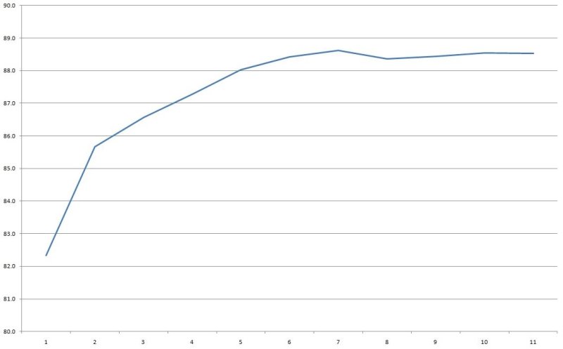
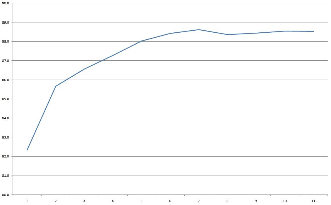
Efficiency was measured from 0.3 to 3.3 A in 0.3 A increments and turned out to be pretty good, at around 88.5%. But most of the credit goes not to the designers, but to the relatively high output voltage, since efficiency usually drops as voltage goes down.
With no load, the output is about 47.69 V and power consumption is 0.7–0.75 W, noticeably lower than the 100 W version.
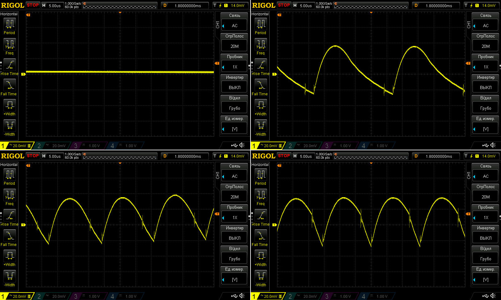
High-frequency ripple with no load and at currents of 1.1, 2.2 and 3.3 A. It's essentially not much higher than on the 100 W version. At maximum current, I measured about 60 mV, which is excellent.
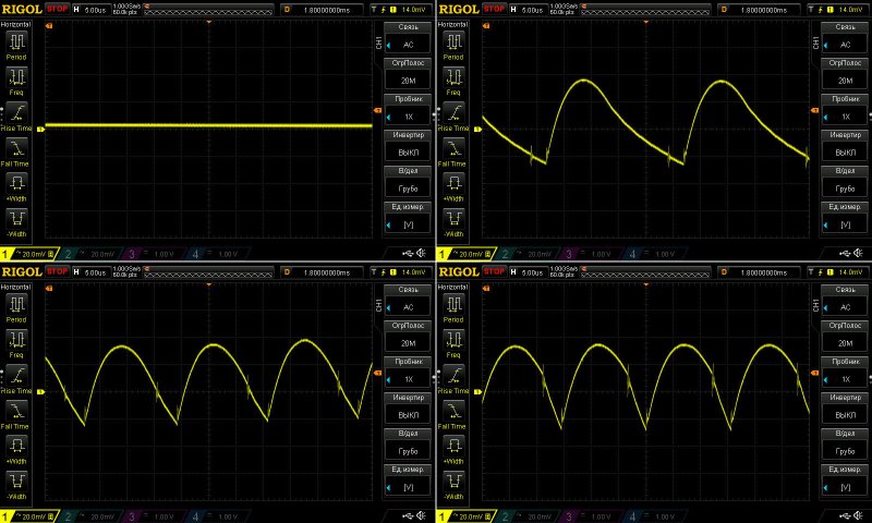
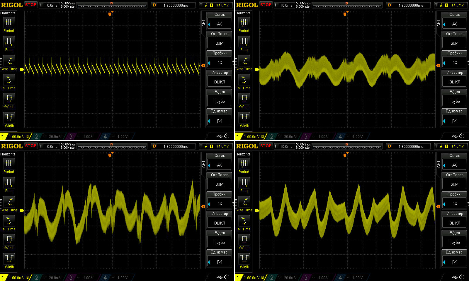
The low-frequency ripple is more odd than large. The peak-to-peak value was about 200 mV, and at 2.2 A it was slightly higher than at 3.3 A.
At one point I thought it was a glitch in the electronic load, but trying ordinary resistors made absolutely no difference. I suspect this is a quirk of the PWM controller, compounded by the rather low input capacitance.
In any case, this ripple isn't critical for the load. Given the 48 V output, it works out to just 50 mV when scaled to a typical 12 V power supply.
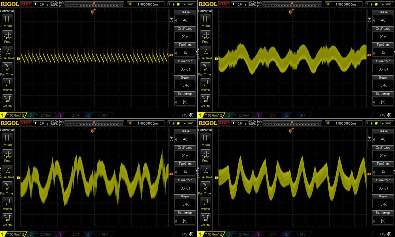
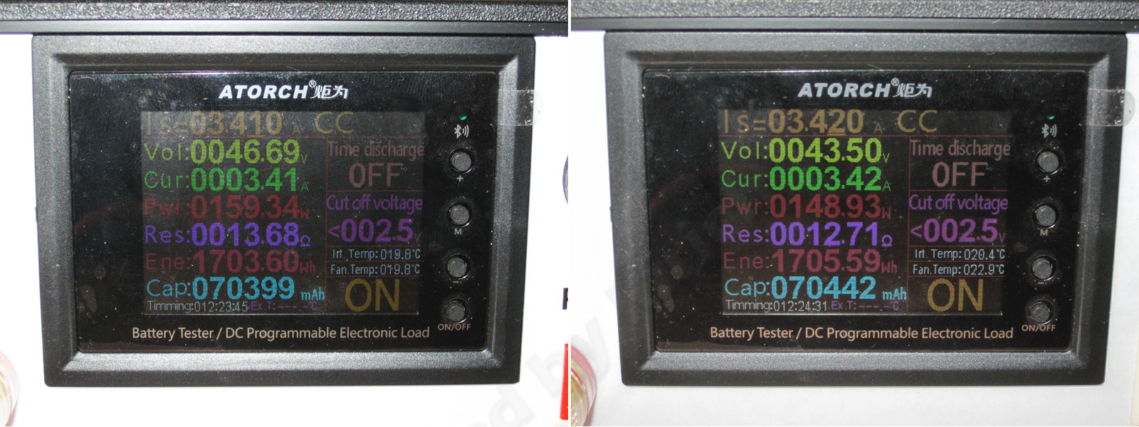
Load tests.
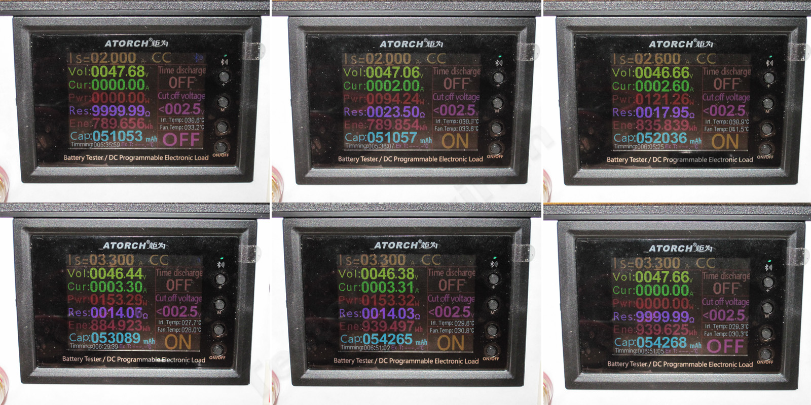
1. Cold power supply, no load.
2. Cold power supply, 2 A load.
3. Warm power supply, 2.6 A load.
4. Warmed-up power supply, 3.3 A load—in other words, essentially maximum load.
5. Hot power supply, 3.3 A load.
6. Hot power supply, no load.
The test results show a fairly large negative relationship between output voltage and load, about 1.3 V. That's a little surprising; temperature only changes the voltage by 20–30 mV.
It's still odd that the output voltage sags so much, even though I wouldn't call the current particularly high. Usually this isn't critical for the load and is well within the standards, but it's still puzzling.
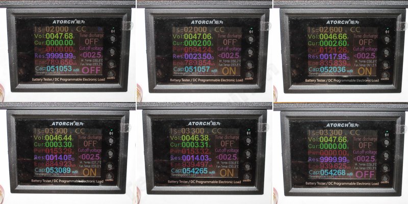
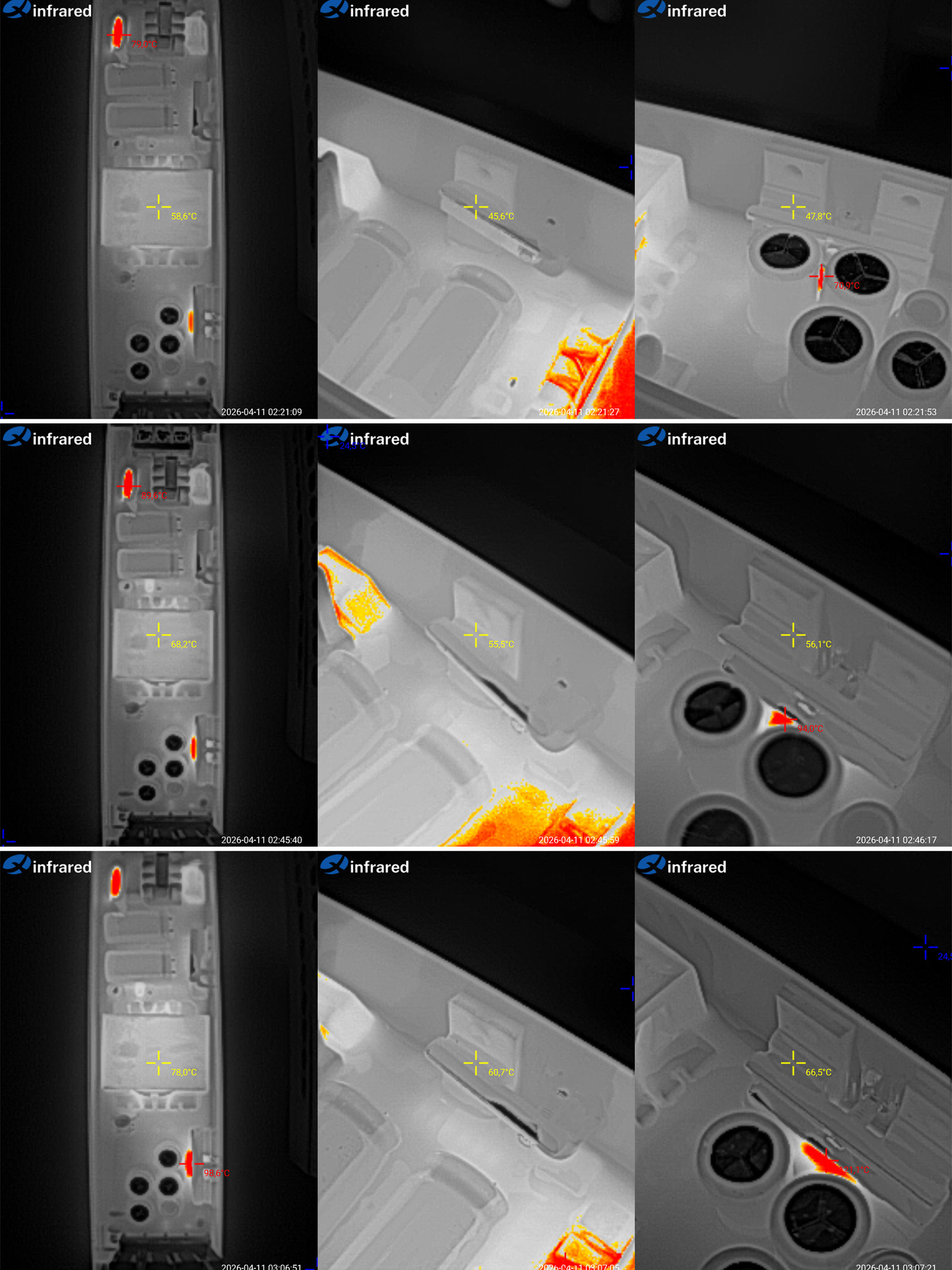
Temperature of the main components at currents of 2, 2.6 and 3.3 A.
2 A — transformer 58.6 °C, transistor 45.6 °C, diode assemblies 48 °C.
2.6 A — transformer 68 °C, transistor 56 °C, diode assemblies also 56 °C.
3.3 A — transformer 78 °C, transistor 61 °C, diode assemblies 66 °C.
In my opinion, these are very good results. The room was cool, though—about 20 °C. The heating pipes were off, and the heating outside hadn't been turned on yet :( Still, I think the power supply can easily handle its rated 150 W with some headroom, at an ambient temperature of around 40 °C.
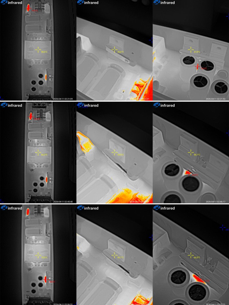
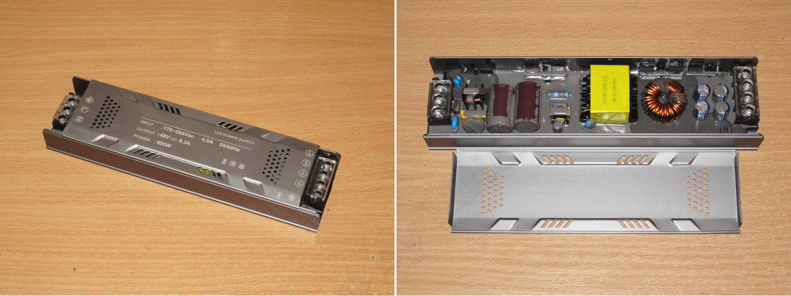
The third model in this form factor: 48 V, 8.3 A, or a whole (not necessarily) 400 W.
This one is a bit larger at 229 × 59 × 29 mm; the only dimension unchanged from the previous models is the height of 29 mm.
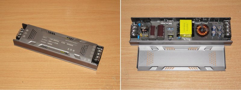
I could say this is just a larger version of the previous models, but it isn't: it uses a completely different topology, a half-bridge converter, which is typical for power supplies in this power range. Though to be fair, they do have a lot in common.
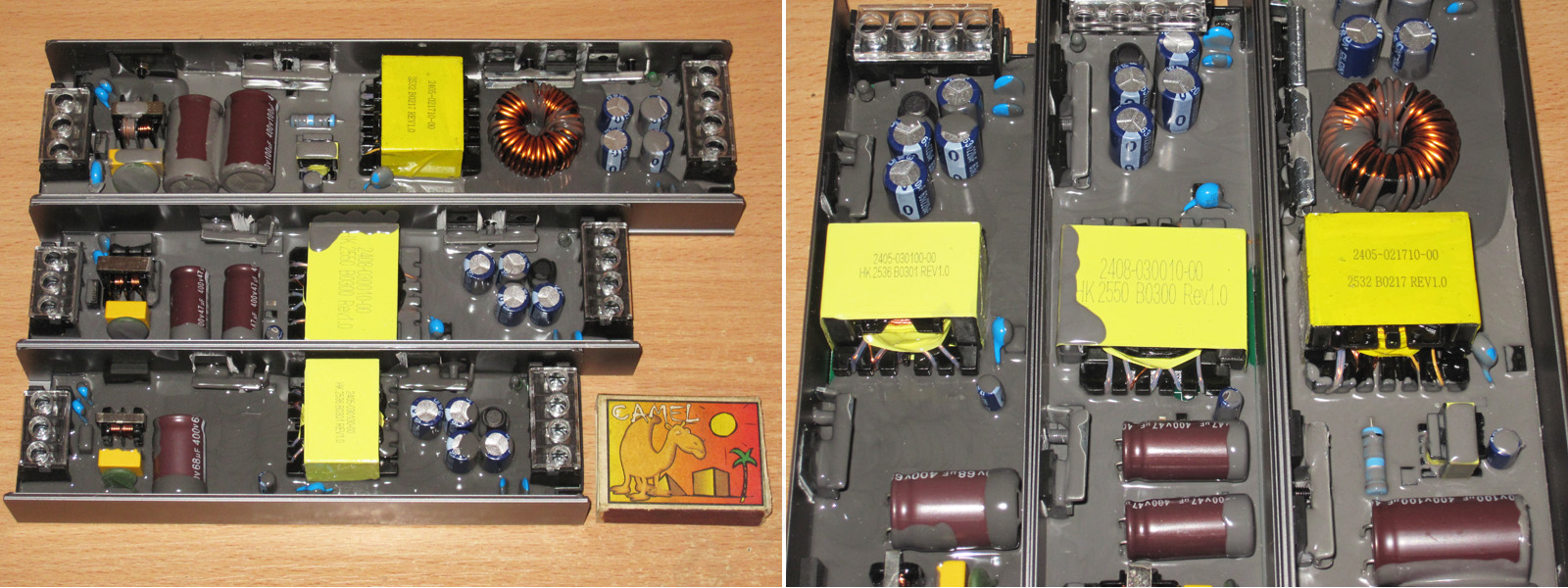
And for comparison, here's a photo of all three models disassembled.
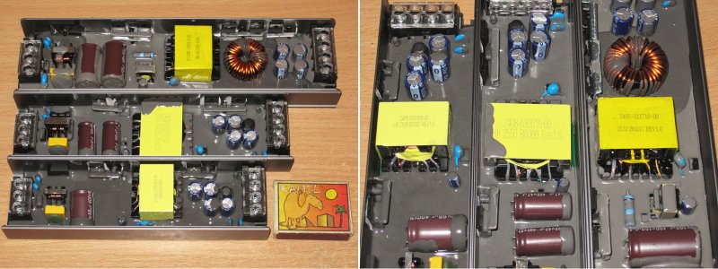
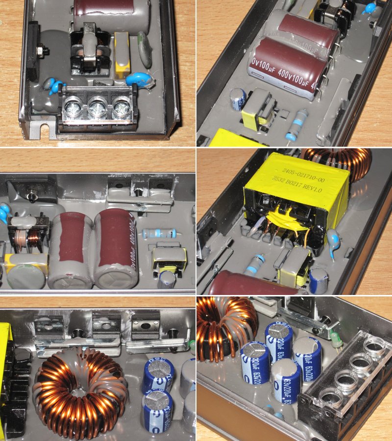
1. The input filter is almost the same as on the previous models, but they've added a varistor.
2. The input capacitors are rated at 100 µF each, for a total of 200 µF, and once again, the tiger isn't getting enough meat. I didn't check the brand, but the PWM controller's supply capacitor is a name-brand Aishi.
3. The diode bridge is bolted to the case. I didn’t check whether there’s thermal paste under it, but there definitely is some under the high-voltage transistors.
4. The transformer is a little larger than the one in the 200 W version, but that’s fine: with this topology, it can deliver more power than the earlier models while staying about the same size.
5. There are no fewer than three output diode assemblies. Next to them is the output filter inductor. It looks very neat, though that’s true of all three models.
6. There are also four 220 µF output capacitors. That’s acceptable here, and as for the lack of an inductor, we’ll check the ripple later.
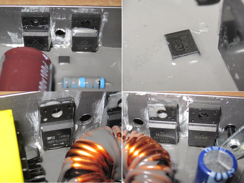
1. The high-voltage transistors come in a pair because of the topology. They’re rated for 13 A and 500 V, which is perfectly fine.
2. Something was sticking out of the potting compound nearby. I thought it was the PWM controller, but it turned out to be just a diode.
3, 4. The diode assemblies are different: one is a 10 A, 200 V Schottky, and the other is a pair of ER1004FCTs, like in the previous models. Don’t be surprised: this isn’t a case of “whatever they found on the floor, they slapped in.” It’s perfectly normal, because the output diodes here work in two circuits, roughly speaking, an upper and a lower one, and the requirements differ.
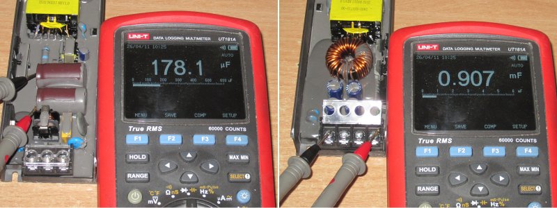
1. The measured input filter capacitance is about 180 µF, which is low again. Still, it’s nice that the stated capacitance is almost exactly what I measured.
2. The total output capacitance is 907 µF, which is fine.
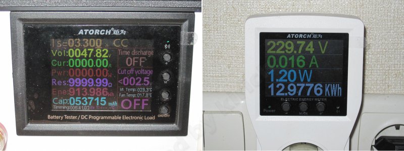
With no load, the output is 47.82 V and power consumption is 1.2 W, which is perfectly normal for a power supply of this rating.
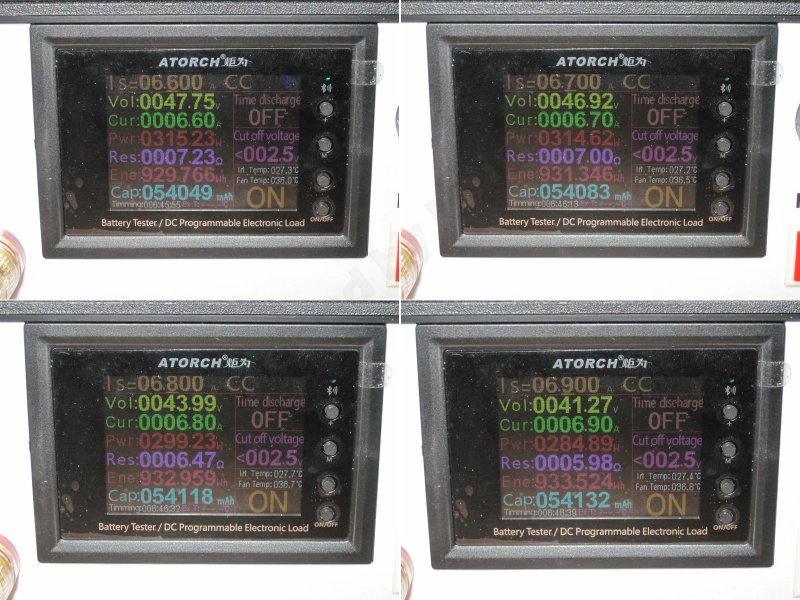
The maximum current I could get without the voltage dropping was about 6.6 A. At 6.7 A it starts to drop gradually, and at 6.9 A the output is already down to about 41 V.
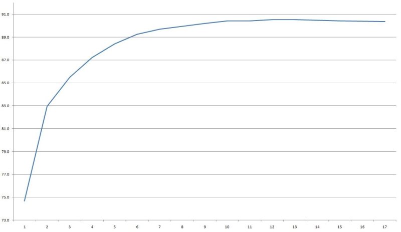
I measured efficiency from 0.4 to 6.8 A in 0.4 A increments, and it came out at around 90%. That’s not bad, but with this topology and output voltage I expected 91–92%. Still, 90% is pretty good.
Ripple with no load and at currents of 2, 4, and 6.5 A.
And here everything looks great: 48 V, 300 W output, no filter, and just 50–60 mV of ripple. What’s not to like?
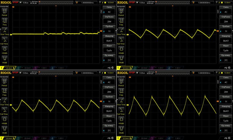
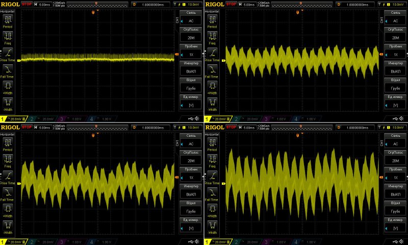
I accidentally captured this waveform with a 5 ms timebase instead of 10 ms, as usual, but it doesn’t really change the picture: there’s noticeable ripple.
And it’s not about the amplitude, which is excellent at just 100 mV, but about the waveform, so to speak. There’s a big difference between 100 mV of overall noise with 50 mV spikes on top, and 20 mV of average noise with spikes reaching 100 mV.
So here the overall amplitude is low, which is very good, but I personally don’t like the shape of the ripple. It may be a characteristic of this design, but I don’t really feel like investigating further.
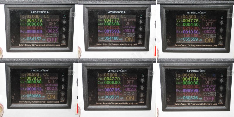
Warm-up test:
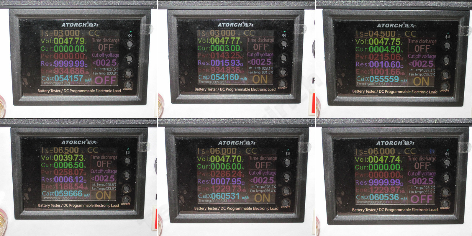
1. Cold power supply, no load
2. Cold power supply, 3 A load
3. Warm power supply, 4.5 A load
4. Fully warmed-up power supply, 6.5 A load.
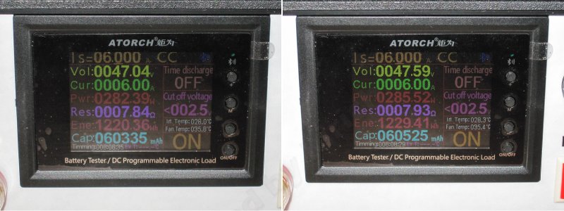
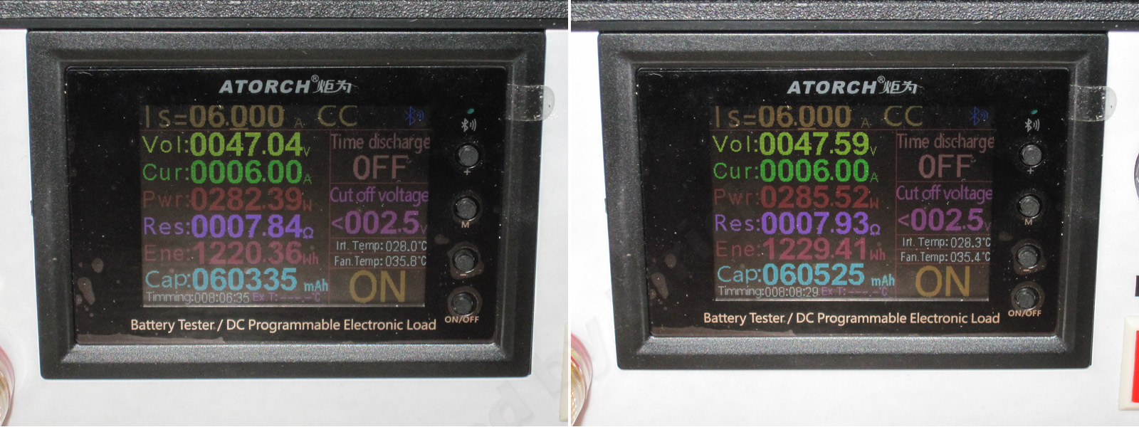
5, 6. During the test I had to reduce the current to 6 A, so these are the results for the hot power supply at 6 A and with no load.
The voltage barely depends on the current: 40 mV against 48 V is less than one-thousandth. The temperature-related voltage change is comparable, at just 50 mV. So there are no complaints here at all. It’s even strange that one factory makes two similar power supplies, yet the 200 W model has a 1.2 V difference while the 400 W model has just 40 mV....
As I mentioned, during testing the voltage dropped at 6.5 A, apparently because the protection kicked in, either due to temperature or a change in the shunt—I can’t say for sure, but it happened. I first reduced the current to 6.1 A, then decided to lower it to 6 A, and that was the right call: it turned out that 6 A is about the limit for the warmed-up power supply. Even at that current, the voltage would sometimes fluctuate, though only slightly.
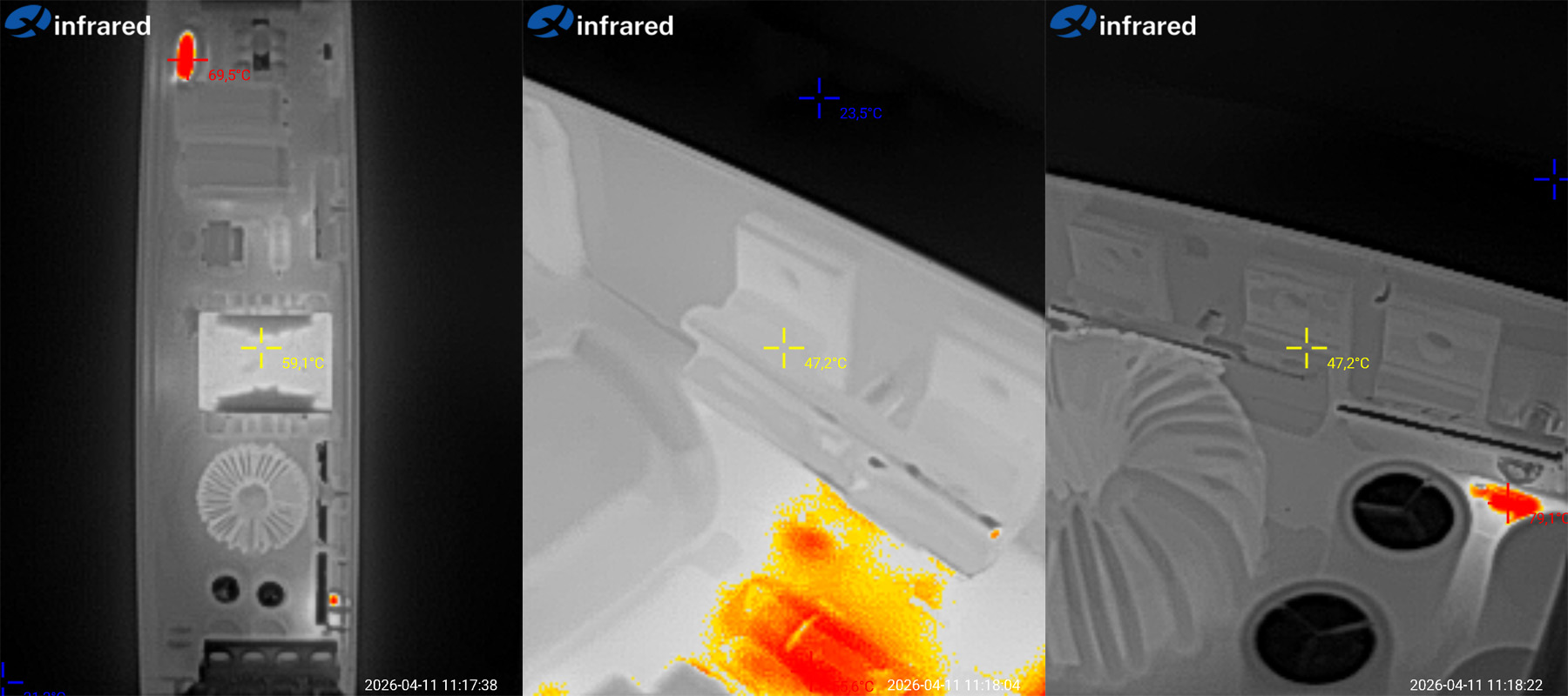
As for temperatures, first, here are the results at 3 A. There’s not much to comment on: everything is almost cold.
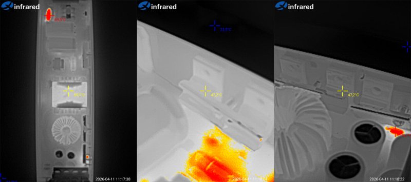
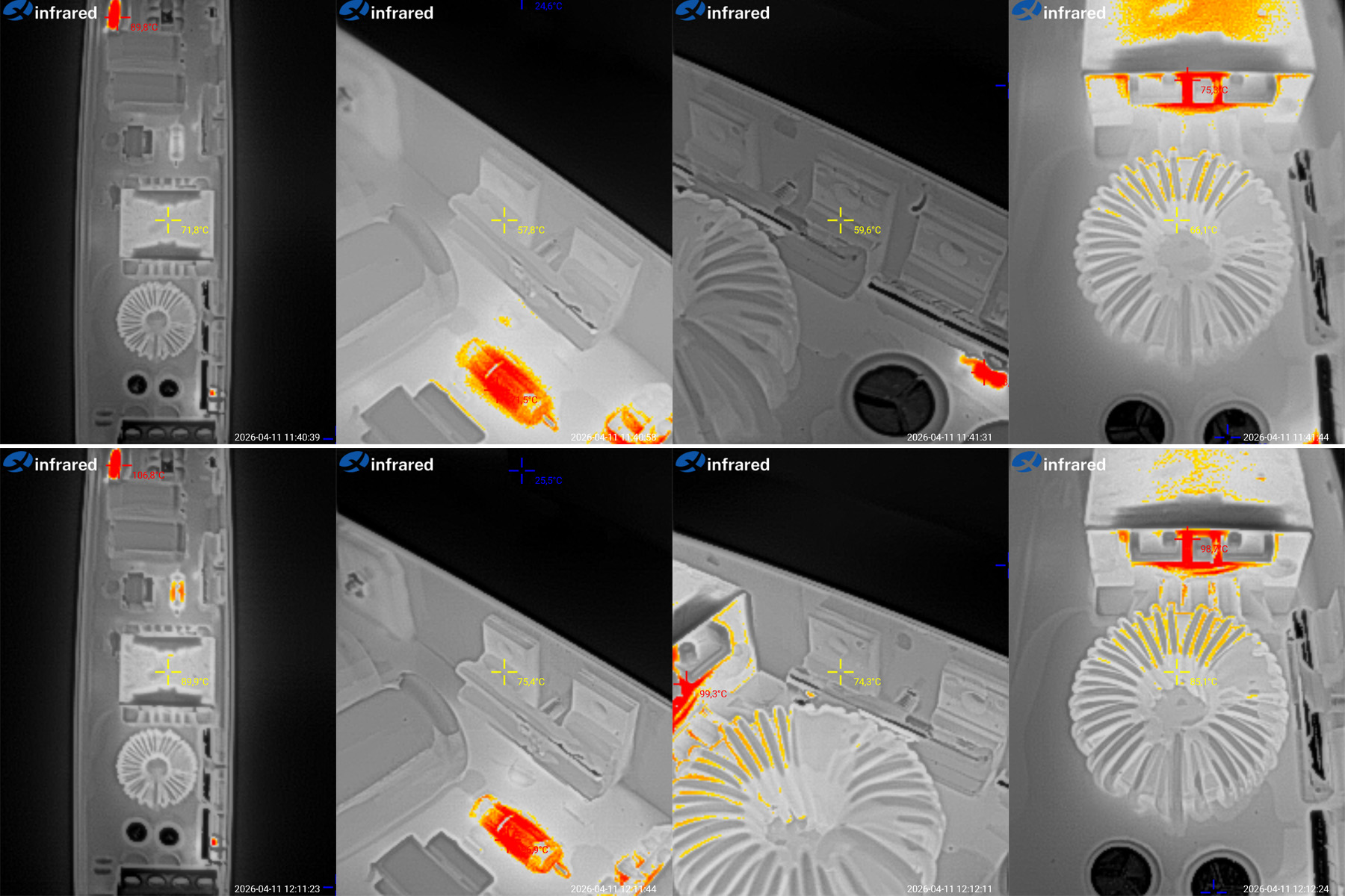
Now at 4.5 and 6 A. The power supply was first warmed up at 6.5 A and then tested at 6 A, but I don’t think that makes a difference.
4.5 A — transformer: 72 °C, transistors: 58 °C, diodes: 60 °C, output inductor: 66 °C. In each case, I measured the hottest spot.
6 A — transformer: 90 °C, transistors: 75 °C, diodes: 74 °C, output inductor: 85 °C.
Based on the results, I’d say 6 A, or 285 W, is too much for it. This is especially evident in the transformer temperature. In my opinion, the power supply’s actual rating is closer to 250 W.
And now we’re gradually getting to much more interesting specimens. When someone first sent me photos of these, the first thing I said was that they looked an awful lot like laptop batteries—if you cut off those pig-tail wires, of course. Otherwise, they’re almost identical.
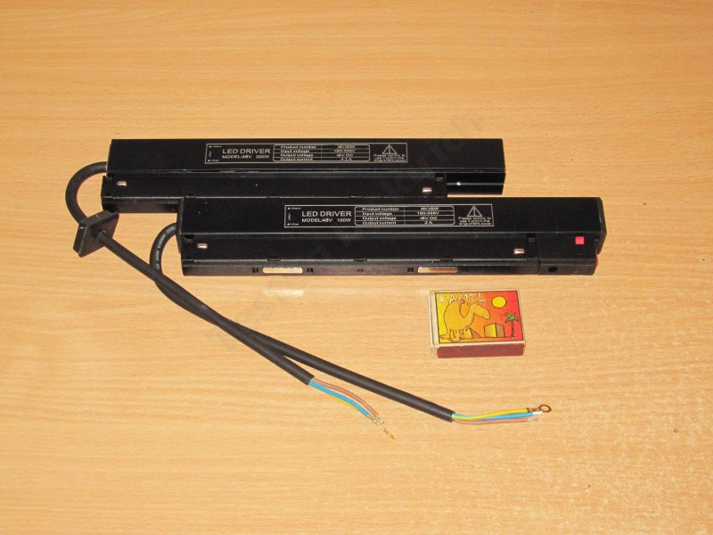
A quick note about the labeling. The cases are marked “LED Driver,” which is completely wrong: a “driver” and a power supply are absolutely not the same thing.
An LED driver is specified by its output current, which it regulates, and the output voltage range over which it maintains that current. You can’t substitute one for the other in any combination, because a driver usually outputs a little more than its stated maximum, while a power supply does not regulate current.
They’re practically identical in construction, but I think that’s down to their intended use. As I understand it, these are power supplies for track lights. There are a couple of magnets on top and two spring-loaded contacts on each side, but power is connected to only one pair, with the same polarity, naturally.
The housing is a U-shaped aluminum profile with a cover. A roughly similar-sized plastic piece with clips and catches is screwed onto it.
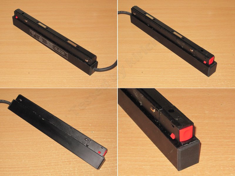
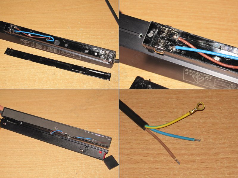
1. The output wires come out at one end. The powered and unpowered contacts are also mounted at different heights, so nothing gets burned if the unit is installed incorrectly.
2. The contacts are spring-loaded. The soldering gets a C-minus; you can tell they’ve cut a few corners.
3. The inside is potted with compound, mostly for electrical safety and heat dissipation, I think, rather than waterproofing. Either way, it’s a plus.
4. The input wires are tinned, and the ground wire has a ring terminal.
The 100 W version measures 252 × 45 × 22 mm.
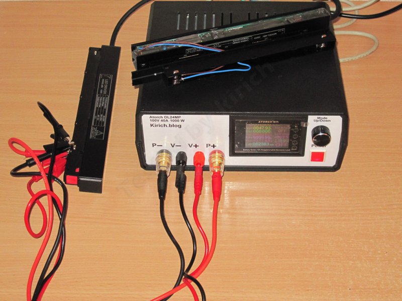
For testing, I again used a 1200 W load based on the DL24MP, connected with four wires right up to the output terminals. That’s the right way to do it, since there’s no way to eliminate the internal wires anyway.
First up are the tests of the 100 W model: 48 V, 2.1 A.
The protection is set very roughly and trips at around 3.5 A, which is far too high for a power supply like this—especially since the load is an LED strip, which fundamentally has no such thing as inrush current.
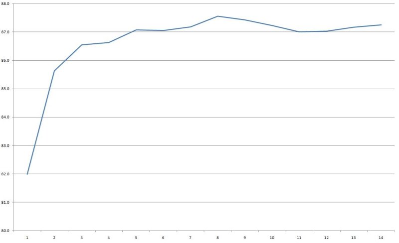
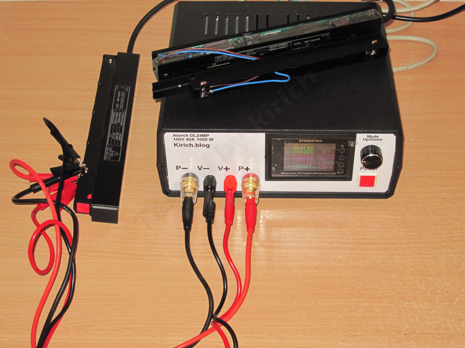
I measured efficiency over a range of 0.2–2.5 A, in 0.2 A increments (the final step was in 0.1 A increments), and got about 87%.
With no load, the output is 47.93 V and power consumption is about 0.2 W, which is pretty good.
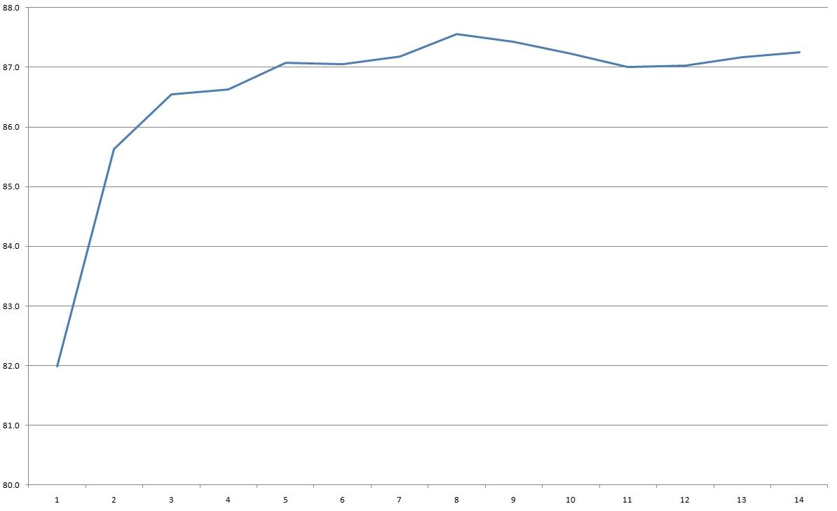
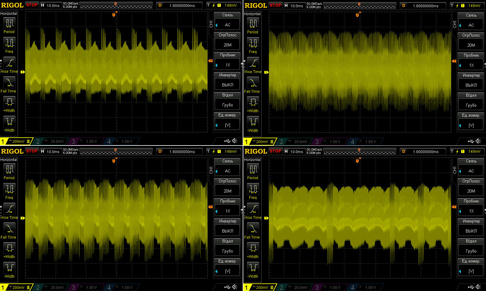
Ripple is noticeably worse than on the previous models. That’s understandable: fitting enough capacitance and filtering into such a compact package isn’t easy, though it’s certainly possible. Maybe they just cut costs.
Below are the results with no load and at currents of 0.7, 1.4, and 2.1 A. At maximum power, I measured around 600–800 mV. If this were a 12 V power supply, I’d probably complain, but here it’s an acceptable result: tolerances increase with voltage, so for a 12 V version this would be equivalent to 150–200 mV.
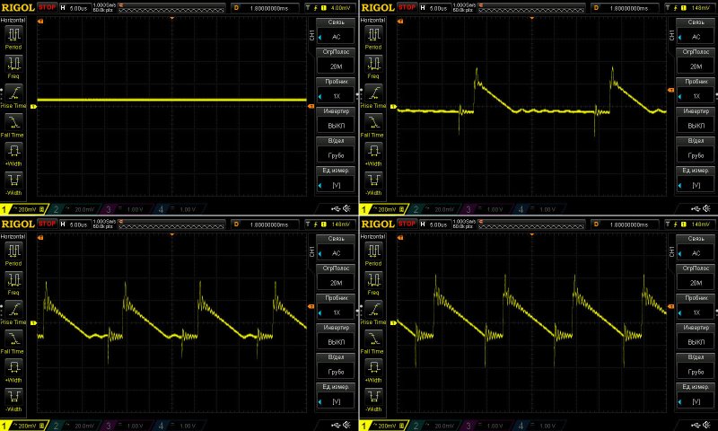
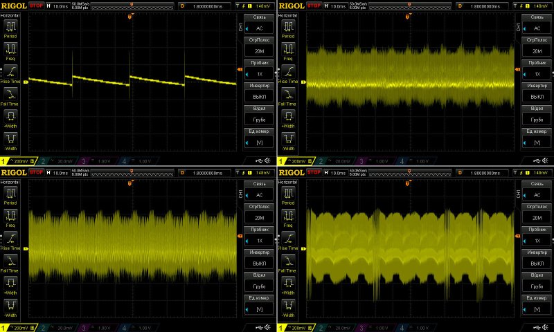
At the low frequency, you can see the “green mode” in action. But I should point out that the 100 Hz ripple itself isn’t all that large. The overall ripple amplitude has barely changed, by the way.
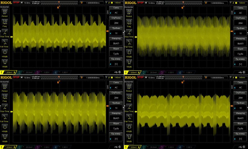
Something else puzzled me a little. It’s not really important, but I couldn’t help noticing it. At high power, even a small change in load current noticeably changes the ripple pattern.
Here are some example waveforms at 1.7, 1.9, 2, and 2.1 A.
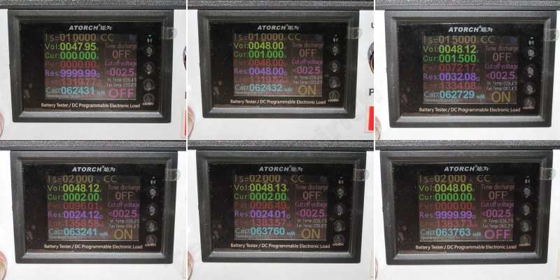
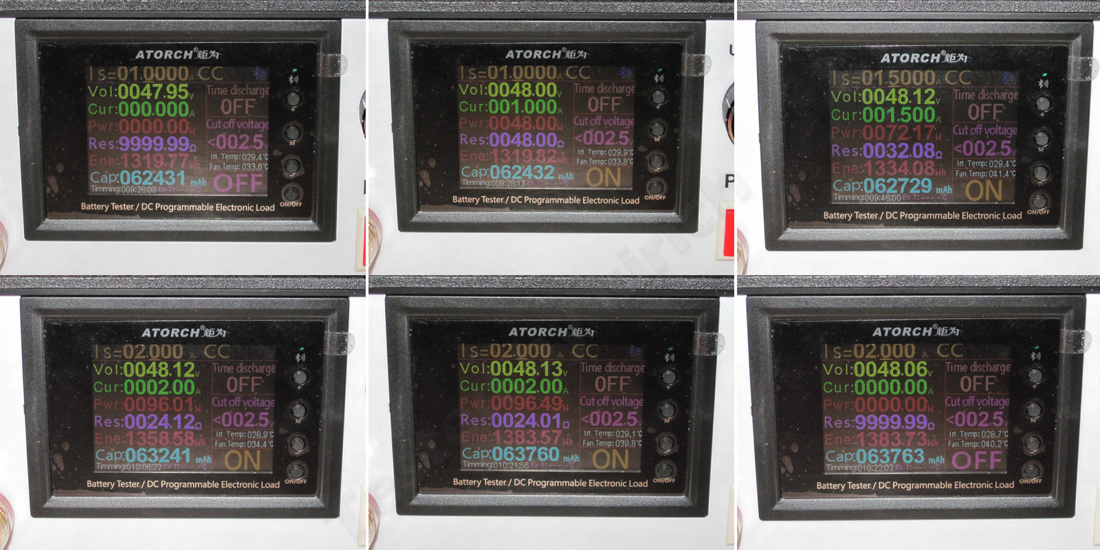
The temperature test was done with the case closed and potted. Here are the intermediate measurements:
1. Cold power supply, no load
2. Cold power supply, 1 A load
3. Warm power supply, 1.5 A load
4. Heated-up power supply, 2 A load
5. Hot power supply, 2 A load
6. Hot power supply, no load.
Several things are immediately apparent here:
1. The voltage increases with load current: the higher the current, the higher the voltage. In my cold tests, I measured 47.96 V at 0.2 A and 48.16 V at 2.3 A. The difference is absolutely insignificant, but it’s quite possible that the voltage is regulated on the primary side here.
2. Based on these tests, the voltage variation with load came out to 70 mV.
3. The voltage varied a little more with temperature, by about 110 mV.
Overall, the results are quite respectable.
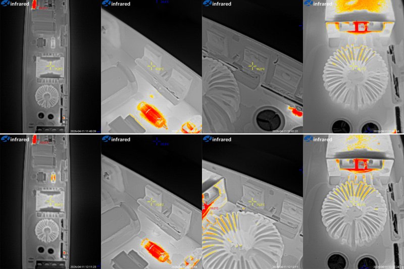
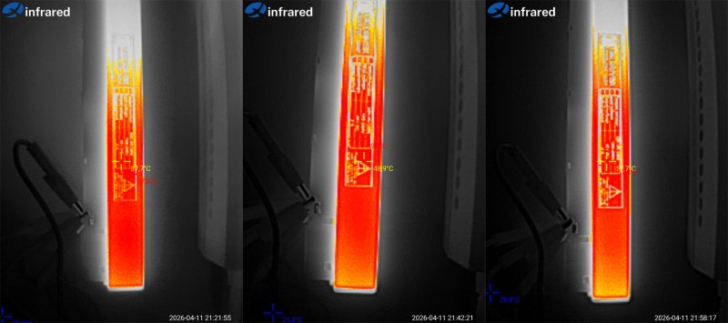
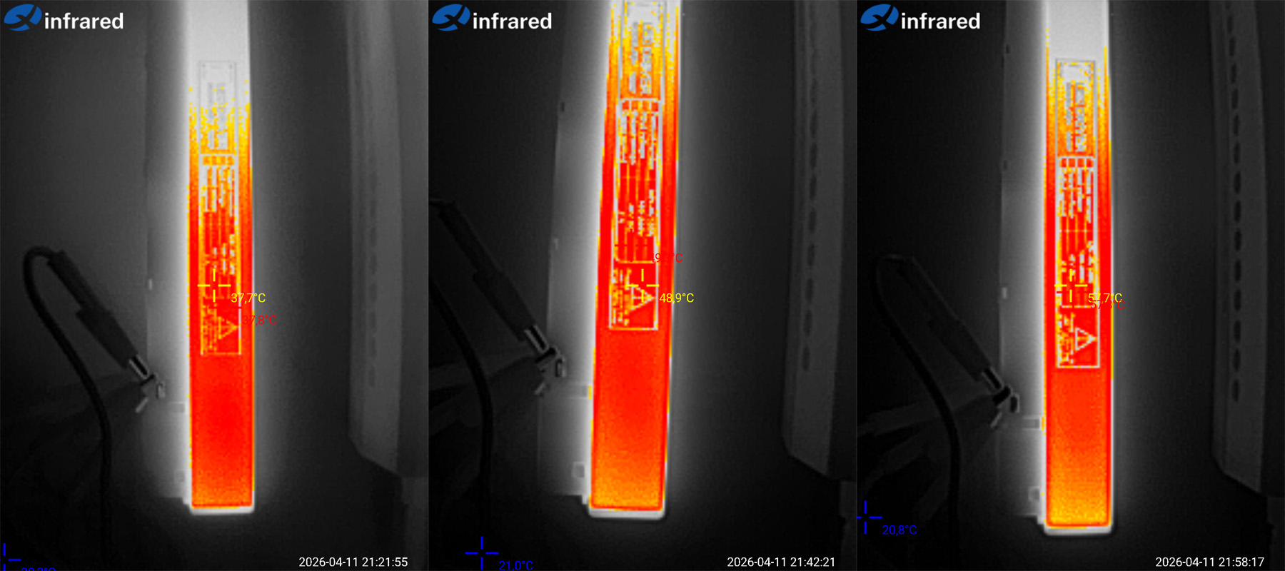
Case temperature at 1, 1.5 and 2 A. The thermal camera does record the maximum temperature, but the readings are barely visible in the photos.
Depending on the current, the temperature was 37.8, 49 and 58 degrees, which is perfectly normal. Besides, since the unit is potted, there are unlikely to be any localized hot spots inside.
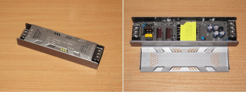
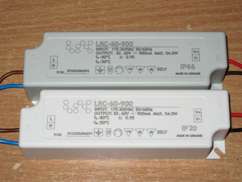
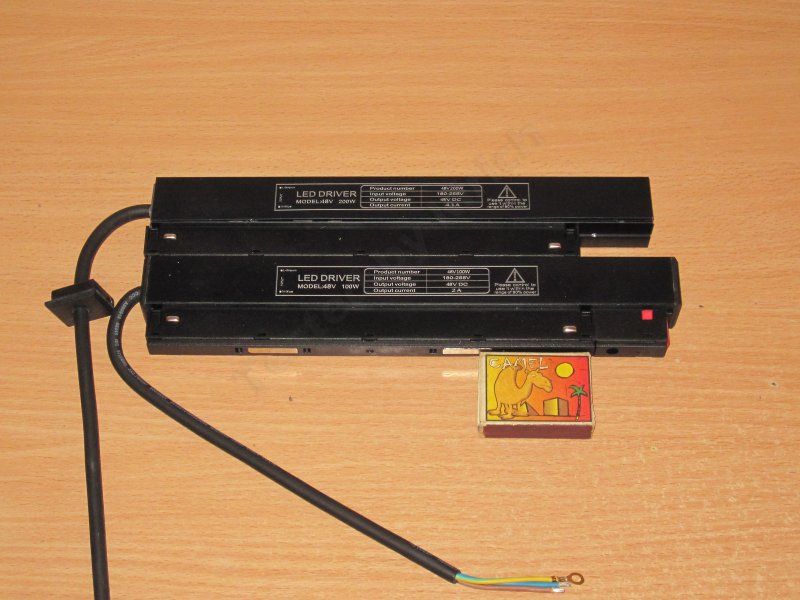
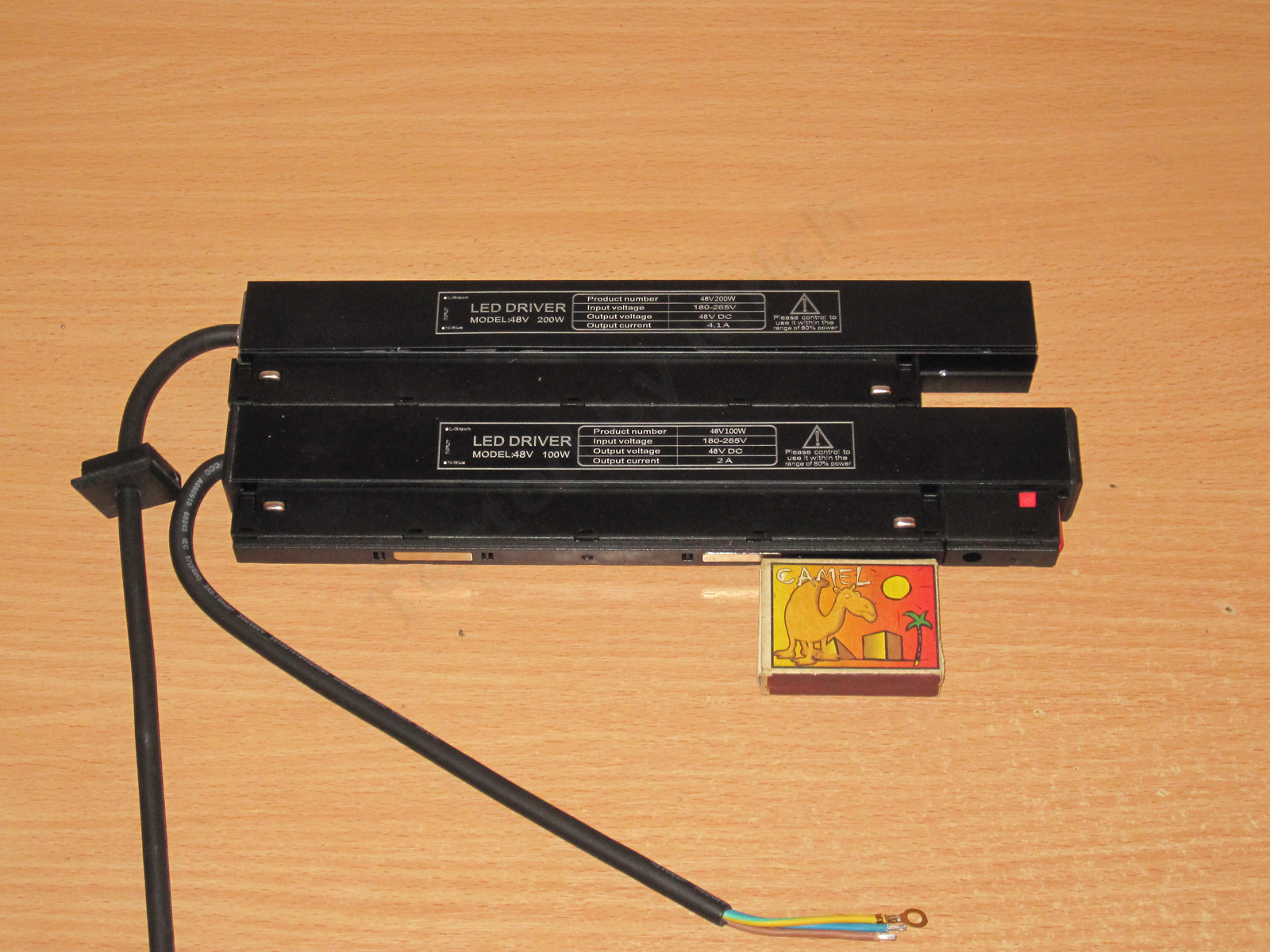
The second unit is twice as powerful, at 200 W. Interestingly, it's even a little smaller—or, more precisely, a little shorter.
For comparison, the dimensions of both units:
100 W - 252x45x22 mm
200 W - 245x45x22 mm
The 200 W model in the photo is missing one end cap and the button retainer. I found them later in the box, since it arrived disassembled, but the dimensions listed are correct.
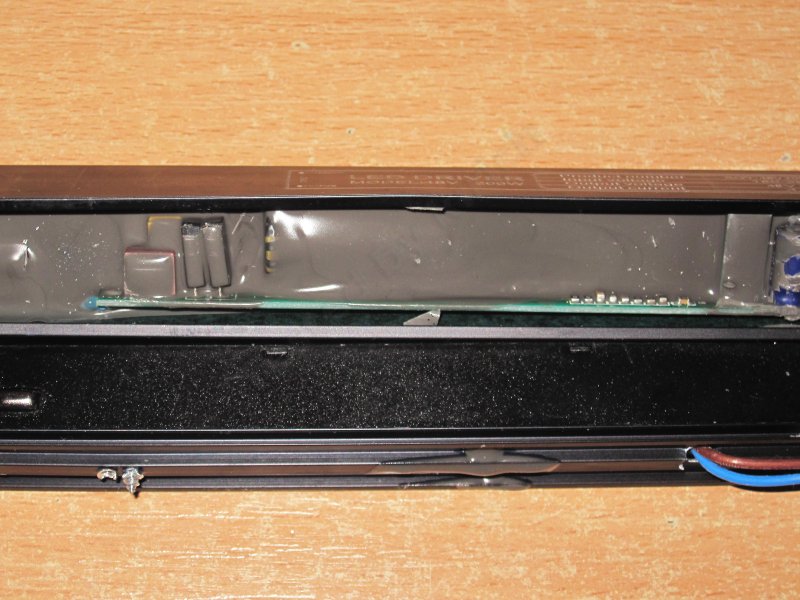
The potting here is less thorough, so you can make out some of the components and see that the board is noticeably shorter than the case.
At this point, I thought this was yet another Chinese 100,500-watt PMPO power supply—the internals looked downright ridiculous.
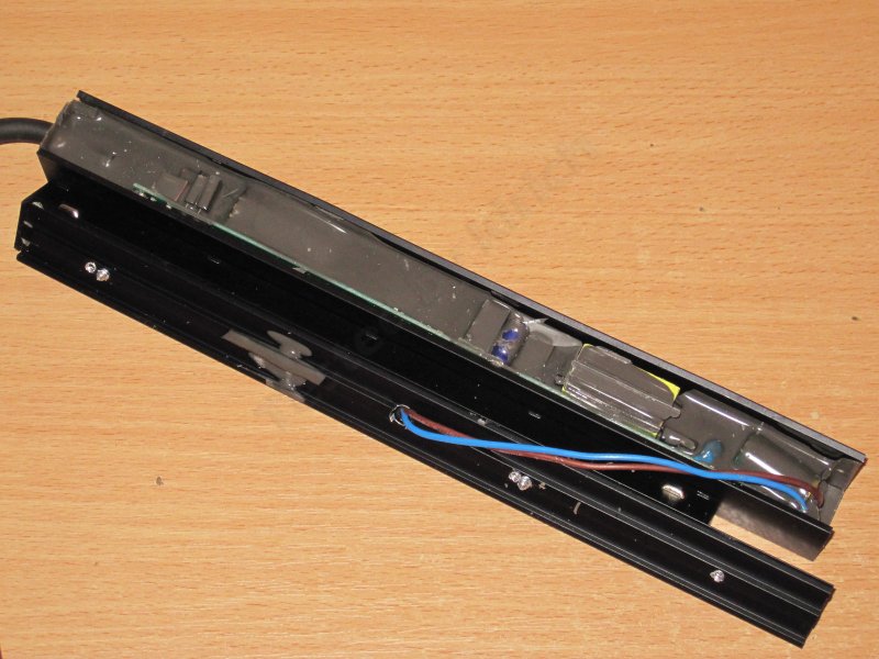
Right away, I noticed the odd self-tapping screws driven straight through the cover. Not only had they clearly missed on the first try, judging by the two holes for each screw, but one of them had gone in literally a millimeter from the transformer. Any closer and it would have cracked the core.
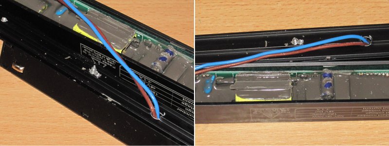
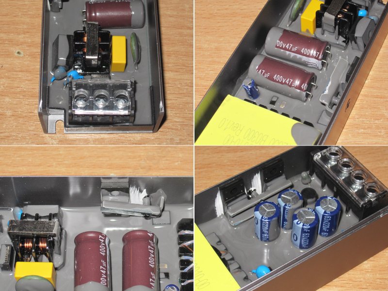
On the input side, you can see an X capacitor, two bridge rectifiers, a fuse and the input capacitor. Judging by its appearance, I doubt it's larger than 68 µF—maybe 82 µF.
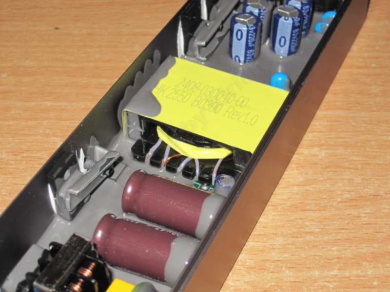
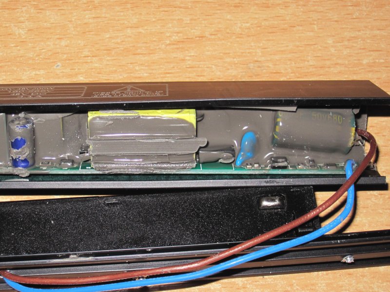
The transformer looks ridiculously tiny for 200 W. To its right are the feedback optocoupler and a Y capacitor, and farther right is the output capacitor, which I have a serious issue with: it's rated for 50 V, but for 48 V you should use capacitors rated for at least 63 V, as in the previous models.
It's hard to make out, but the safety looks at least adequate, if not excellent. The potting helps, too.
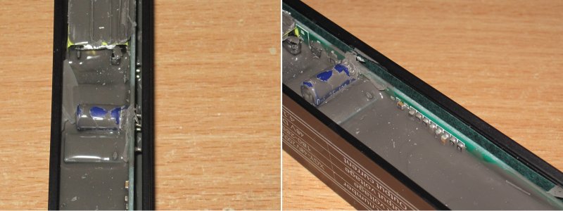
I also noticed that although the board is relatively far from the case, some component leads stick out. I was about to criticize it, but then I saw that the side wall of the case is lined with electrical insulating paper, so it's all fine here. And remember, this power supply is intended to be grounded.
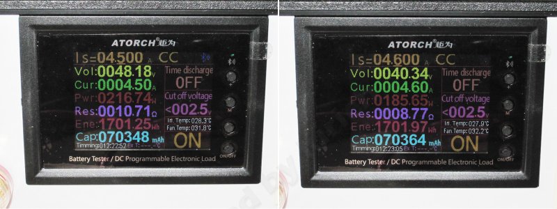
Here the overcurrent protection is set correctly. The unit still works normally at around 4.5 A, and starts dropping the voltage at 4.6 A, so the maximum output power is about 215–220 W.
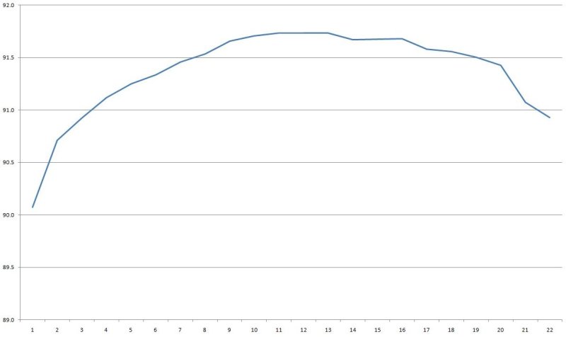
Efficiency was measured from 0.2 to 4.4 A and came in above 91%, which is very good for such a compact unit.
With no load, the output is 48.2 V and power consumption is about 0.6 W. No complaints at all.
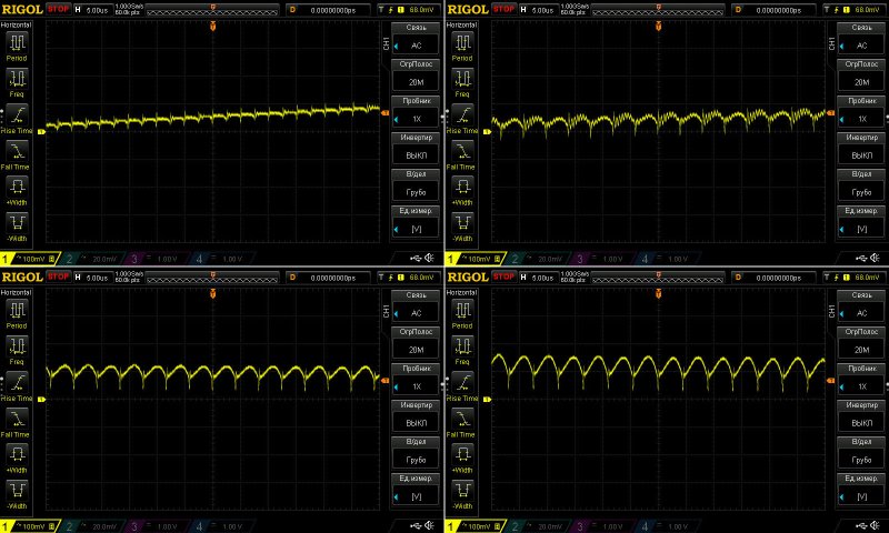
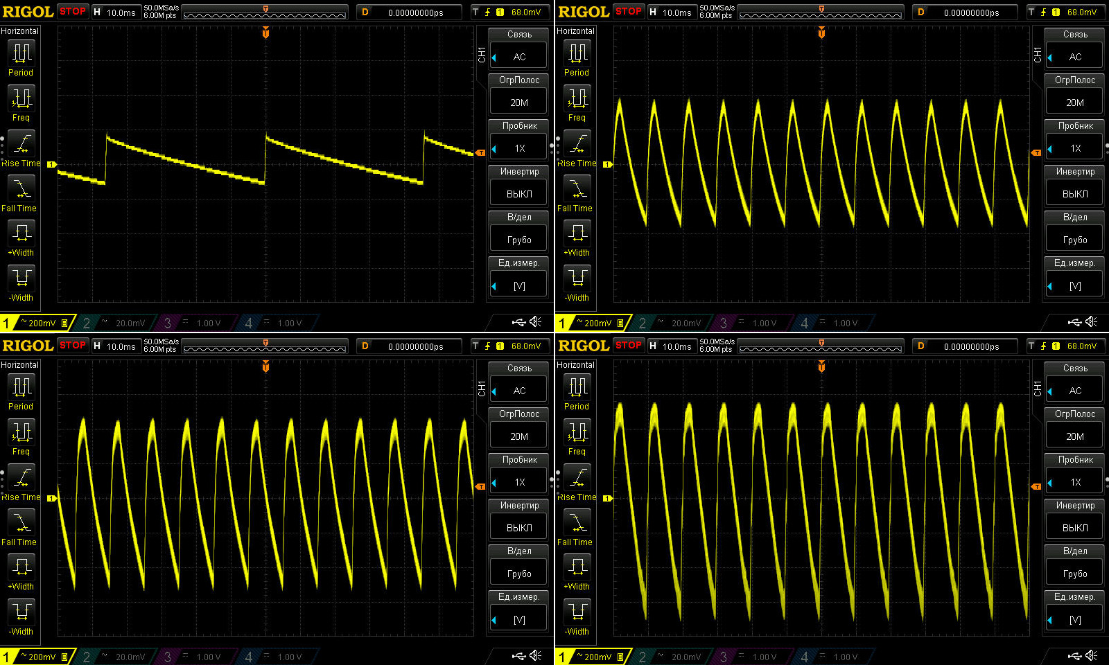
The ripple wasn't quite as good here as I'd hoped, either. I checked it with no load and at 1.4, 2.8 and 4.2 A.
At high frequency, there's basically nothing to complain about: 100 mV at maximum load is genuinely great. But that odd waveform with no load immediately raised a red flag.
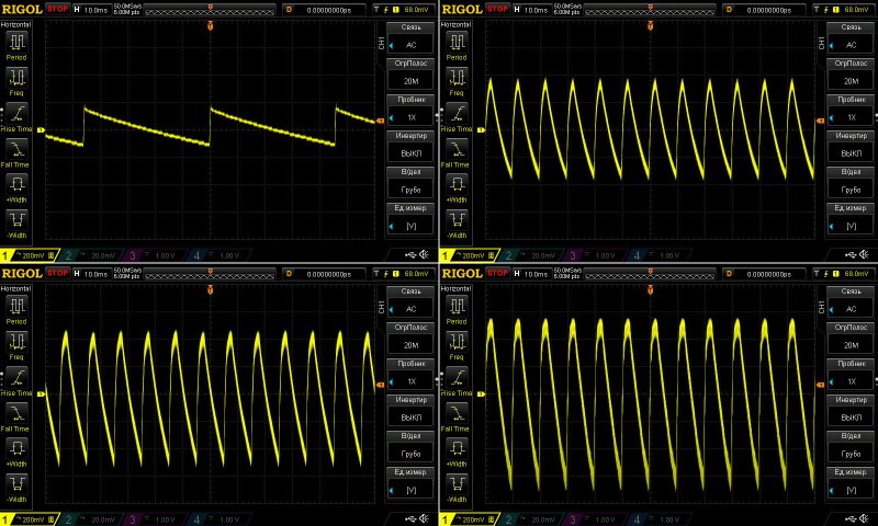
And now at low frequency.
The explanation for the “crooked” high-frequency waveform was immediately apparent: it's simply the characteristic behavior of “green mode.” Everything is fine.
Under load, though, the waveform looks worse. I even got the impression that there's no input capacitor at all, because the middle section of the waveform—the part where 100 Hz spikes usually appear—is completely absent. Instead, there are clear 100 Hz ripples at the output, with a full amplitude of 1.2 V.
Well, 1.2 V isn't that bad against 48 V, but the point is that if you power an LED strip with this supply, those 100 Hz ripples could cause some flicker, unlike the high-frequency ripple, which is practically perfect here.
I'll think about it some more, but I'd like to take this unit apart to find out whether I'm right that the input capacitor is either open-circuit or disconnected. It clearly isn't a matter of capacitance, since the ripple is present even at low current. Or perhaps this is a very characteristic behavior of the PWM controller; that's theoretically possible, too.
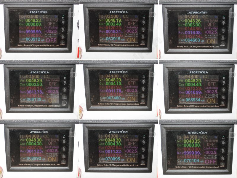
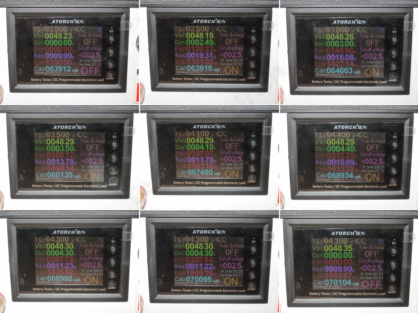
And now for the most interesting part: the warm-up test. This is a test of a very compact power supply rated at 200 W!
1. With no load and the unit cold, we get 48.23 V.
2. Cold, at 2.5 A
3. Then at 3 A
4. Warm, at 3.5 A
5. Warmed up at a current of 4.1 A.
6, 7. With the unit thoroughly warmed up, I first raised the current to 4.4 A, but took pity on it and eventually lowered it to 4.3 A.
8, 9. The warmed-up unit at 4.3 A and with no load.
Overall, I can say that the output voltage barely depends on the load: just 50 mV. This may simply be due to voltage drop in the output wires leading to the terminals. After warming up, the voltage rose by 120 mV, which is also a very good result, especially considering the output voltage.
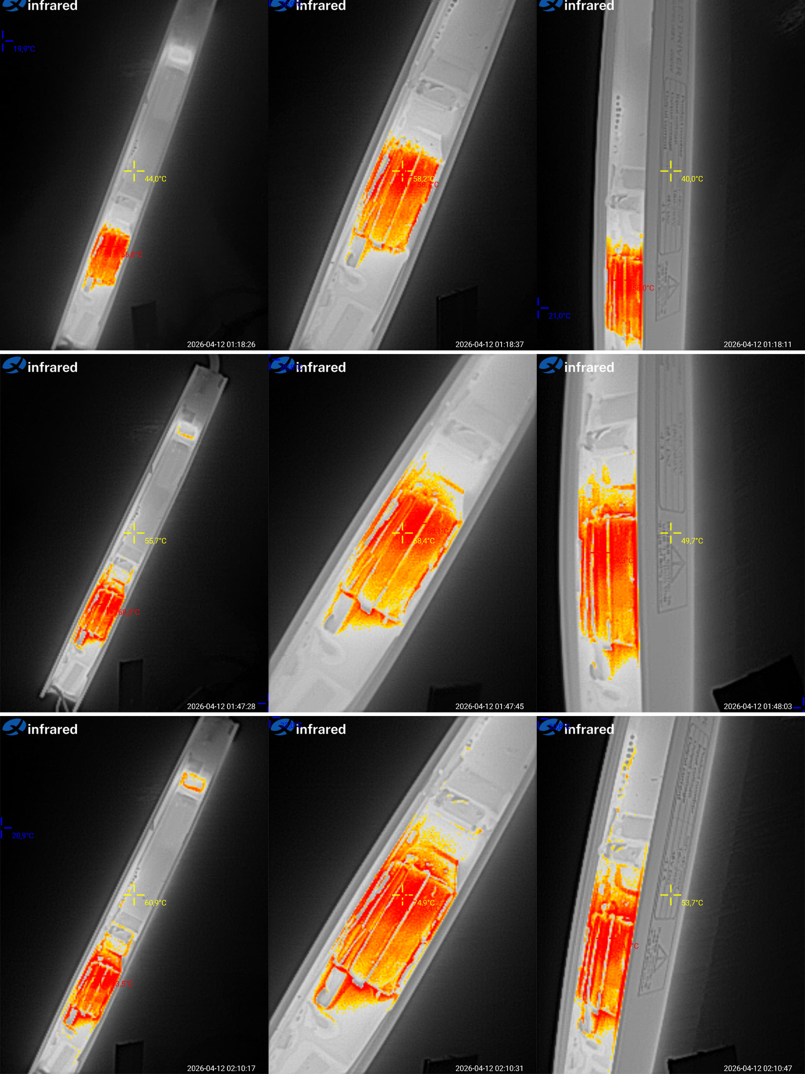
And here are the temperature measurements.
First, a quick look at 2.5, 3, and 3.5 A.
2.5 A — Around the input capacitor: 44°C; transformer: 58°C; side panel: 40°C.
3 A — 56°C, 68°C, and 50°C, respectively.
3.5 A — Likewise, 61°C, 75°C, and 54°C.
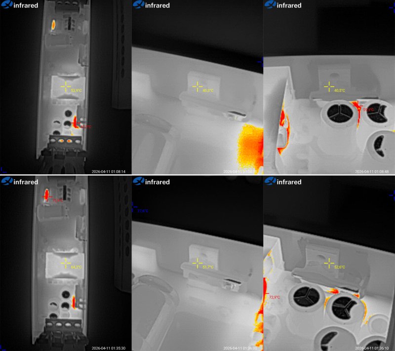
So far, no complaints at all. The power supply handles a 170 W load with ease. The hottest part is the transformer, but 75°C is a normal operating temperature, especially since I was essentially measuring the winding temperature; the core is usually cooler.
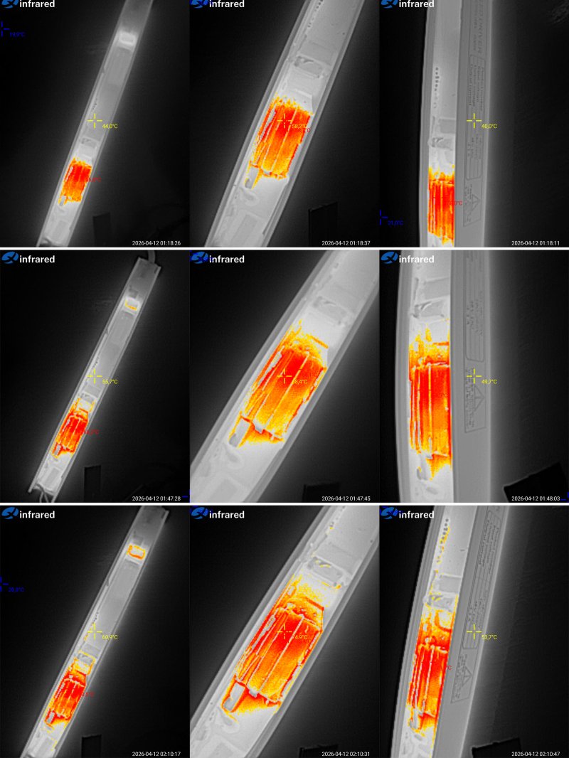
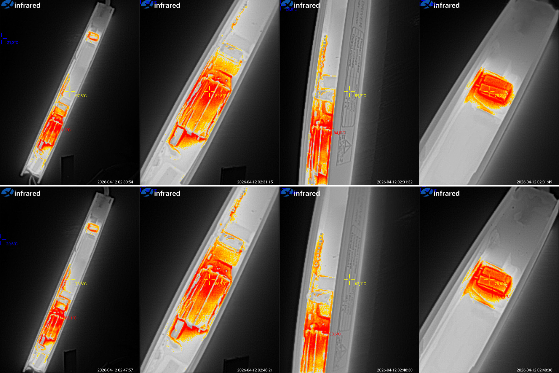
Now things get more interesting: currents of 4.1 and 4.3 A.
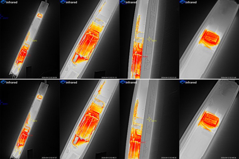
4.1 A — Around the input capacitor: 68°C; transformer: 83°C; side panel: 59°C; input diode bridges: 75°C.
4.3 A — Around the capacitor: about 74°C; transformer: 87°C; side panel: 62°C; diode bridges: 79°C.
I take my hat off to it. I wasn't sure the power supply could deliver the claimed 200 W—or, more precisely, 4.1 A. In practice, it performed excellently even at 4.3 A, delivering 208 W, or about 104% of its rated load. I think it uses a decent circuit design, and the potting compound also played an important role by spreading the heat to the case and preventing localized overheating.
This power supply turned out to be very convenient for testing: it is potted, and you can measure the transformer temperature.
Conclusions, in the same order as the models tested
100 W — Overall, I liked it: quality construction, potting, low temperatures. There’s basically nothing to complain about. Actually, no, there is. This is an honest 100 W power supply with an honest 100 W rating, but its protection is throttled, limiting you to no more than 80 W. Seriously, that’s a very strange and unusual choice. We’ve seen all kinds of power supplies, but it’s extremely rare for a manufacturer to cut the power back so drastically themselves. Mark it as a 75 W unit and you’ve got an excellent power supply with plenty of reliability margin. That’s a fact.
200 W — The situation is somewhat similar to the 100 W model. The claimed 200 W would be very close to the actual maximum, so perhaps this really is a 200 W unit, albeit one running right at its limit. Its protection is also throttled, kicking in at around 150–160 W, which I consider its true continuous power rating. In other words, mark it as 150 W and you get the actual power, neat construction, decent components, and a perfectly reasonable service life. The only thing I’d improve is the input capacitor capacity: increase it at least a little, from 84 to, say, 120 µF.
400 W — Much of the above applies here too: the actual limit is noticeably lower than the claimed rating, the components are decent, and the input capacitor capacity is also on the low side. But unlike the previous models, 400 W would overload this one, so the current limit of 300–310 W seems entirely justified. I recommend keeping the continuous load to no more than 250 W. And at that load, an input capacitor capacity of 180 µF seems perfectly acceptable. So yes, it’s a great unit, but relabel it as 250 W and that would be both honest and accurate. One plus is that it seems to have thermal protection, at least the protection threshold clearly depends on temperature.
100 W track-mounted — It would be a good power supply with an honest rating, and I could recommend it if not for at least one issue: the protection current is set much too high. It might handle 3–3.4 A continuously, but I wouldn’t risk it. Otherwise, it caught my interest: it has very good potential and delivers its rated power.
200 W track-mounted — This power supply is both great and bad. I really liked not only its actual output power, but also its stable operation, low high-frequency ripple, and well-set protection threshold. If it weren’t for the odd 100 Hz ripple, I might say this is exactly what an honest, high-quality power supply should look like. But besides the 100 Hz ripple (which may be a defect in this particular unit), I have a major concern about the output capacitor: it’s rated for 50 V, and that’s not acceptable. It should be at least 63 V! I suspect the 100 W version has the same issue.
Now, briefly.
The first three are good power supplies, with good construction and components and reasonable temperatures. But all three have lower actual output power than claimed. For the 100 W and 200 W models, that’s more of a feature; for the 400 W version, it’s a bug, because at 400 W it would simply overheat. Sure, you could sell it as a 400 W unit with protection at 300 W and an actual rating of 250 W, but I think it’s simpler to label it as 250 W from the start and save both the customer and yourself the confusion. Strictly speaking, the correct figures would be 75-150-250, not 100-200-400.
As for the two track lights, they turned out better than I initially thought. At least, I have no complaints about their power output or heating. The first one has an issue with the protection current, while the second has problems with ripple and the output capacitor. Otherwise, they're great power supplies.
That's all for now. I hope you found this useful and interesting, and of course, thanks to Vitaly for sending the samples for testing.
Why? Because there are five power supplies: three of one type and two of another. They’re also split into two pairs—100 and 200 W—and one on its own at 400 W.
So today I’m reviewing two 100 W power supplies, two 200 W units, and one 400 W unit. I think it’ll be interesting :)
A reminder: to keep up with new posts on the blog, I recommend following me on Instagram, where I’ll post notifications about new articles and maybe just write about something interesting — link to account
You can also subscribe to updates and new articles on the Telegram channel — https://t.me/KirichBlog Just a note: discussion of reviews and articles is enabled on the channel, and you can also just chat. I recommend it.
48 V power supplies are quite common, but I didn’t know they were used in lighting systems. I’m used to seeing 12 or 24 V. The advantage of a higher voltage is lower current at the same power, which means less voltage drop along the same strip. Of course, there are drawbacks too—there always are.
Similar power supplies are also sometimes used to power simple bench power supplies, so perhaps this review will be useful for that as well. Anyway, let’s get started.
As I said, I was sent five power supplies, all rated for 48 V, with power ratings of 100, 200, and 400 W—or at least that’s what the specs say. Three have a conventional form factor, or at least one I’m familiar with, while the other two are quite unusual.
I’ll start with the conventional ones and save the two unusual ones for dessert :)
All three power supplies have the same connection layout: three terminals on the mains side and four on the output side. The terminal blocks have covers, but there are holes in the covers, so you can clamp the wires without even opening them. Convenient.
The first one is the 100 W model: 48 V, 2.1 A.
Dimensions: 175 × 48 × 29 mm
And to get ahead of myself, this whole series looks very familiar. I’ll have to dig through my test results and articles, because I’ve definitely come across it before—maybe in a slightly different case and for a different voltage, but that’s not really important.
The circuit board is coated with protective compound, making these power supplies more resistant to high humidity. But keep in mind that they’re definitely not sealed. In any case, the compound serves several purposes at once: moisture protection, improved electrical safety, and slightly better heat dissipation.
1. The input has an almost complete filter. There’s no varistor, but I think the more important thing is that there’s a thermistor. You can also see the Y capacitors for suppressing interference, which suggests they didn’t cut too many corners.
2. The input capacitor is 68 µF, which is a bit small, at least for 100 W. But keep in mind that the specified input range is narrow: 176–264 V. Even so, the capacitance is right on the edge.
To explain why I mentioned the input voltage range: the lower the input voltage, the more input capacitance is needed. Power supplies can be designed for a narrow range, something like 85–130 V or 198–255 V, or a wide range, 85–255 V. The exact values can vary, but the important point is that if a power supply is designed for a wide range and doesn’t have an active power factor correction circuit or a 115/230 V switch, it has a harder time operating at low voltage. Most of the strain falls on the bridge rectifier, input capacitor, and converter transistor.
Okay, I’ve probably overloaded you with details. In short, for the specified range and power, the input capacitor is usually 82–100 µF; for a wide input range, the capacitance is increased by about 1.5 times.
3. The bridge rectifier and high-voltage transistor: the bridge rectifier is just sitting there, while the transistor is pressed against the heatsink, with thermal paste applied. Good.
4. A nice-looking transformer. I couldn’t resist taking a photo. At least some of the windings use stranded wire, which is also a plus.
5. The output diode assembly is also pressed against the case, and there’s thermal paste here too. The LED covered in compound made me smile—I didn’t even notice it at first. Camouflage level 80 :)
6. The output has four 220 µF, 63 V capacitors, along with an inductor to reduce ripple. As always, I’d like to see more capacitance: "pills for greed, and lots of them" :) In my opinion, 330 µF would look better, but this is fine too.
After testing, I got around to checking the power components in all the power supplies.
1. A 4 A, 650 V transistor—perfectly adequate.
2. The output diode assembly is an ER1004FCT, rated for 400 V and 10 A. It’s a ultrafast diode, of course, since Schottky diodes are generally not used at these voltages. But it has plenty of headroom for this power supply.
1. The measured input capacitor capacitance came to almost 70 µF. Damn, I think this is the first time the actual input capacitor capacitance has exceeded the rated value.
2. The total output capacitance is 930 µF, all good.
For all the tests, I used a 1200 W electronic load based on the Atorch DL24MP controller. Someone might ask: why not the trendy new BW600?
Yes, I’ve almost completely switched to building 1200 W versions with the BW600, but for testing power supplies, the old 24MP is definitely a better fit. It may be noticeably behind the new model in hardware and software, but that one is more geared toward battery testing. It’s a shame Atorch discontinued it, but I still have a small stock :)
Even though the voltage is high here, I still used a four-wire connection. Why not, especially since it was convenient.
I messed up a bit with the photo of the overload protection test, and it wasn’t easy to do anyway, because it turned out that the power supply not only has a clear threshold-based protection, but also shuts down at 1.7 A. So in practice, its output power is around 77 W. By the way, it’s worth noting that at this power level, the input capacitor’s capacitance is quite sufficient for normal operation.
Efficiency was measured from 0.2 to 1.6 A in 0.2 A increments and came out to 85–86%, which is pretty good. I’ll also point out that the graph shows efficiency rising toward the end of the test. This indirectly suggests that the power supply is being held back a little and could actually deliver more.
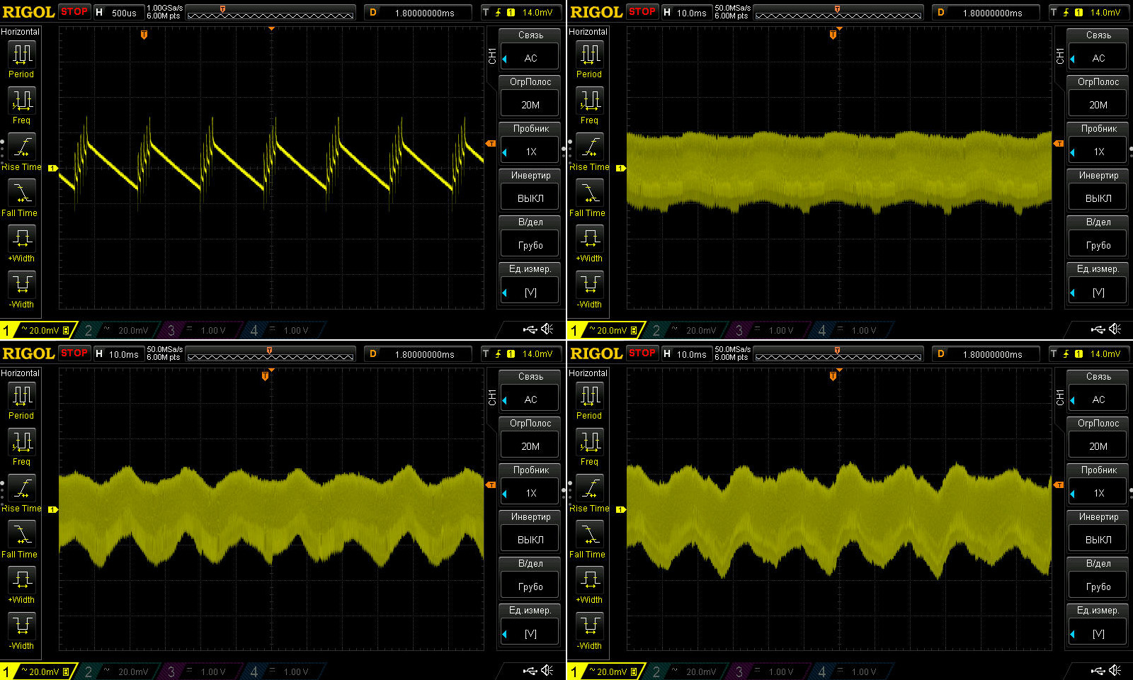
As for ripple, at least at high frequencies it looks really good: even at 1.6 A, it’s only 50 mV, with no spikes. Considering the 48 V output, that’s a very pleasing result. The low ripple is almost entirely thanks to the output inductor, and I’m glad they didn’t skimp on it.
Ripple was measured with no load and at currents of 0.5, 1, and 1.5 A.
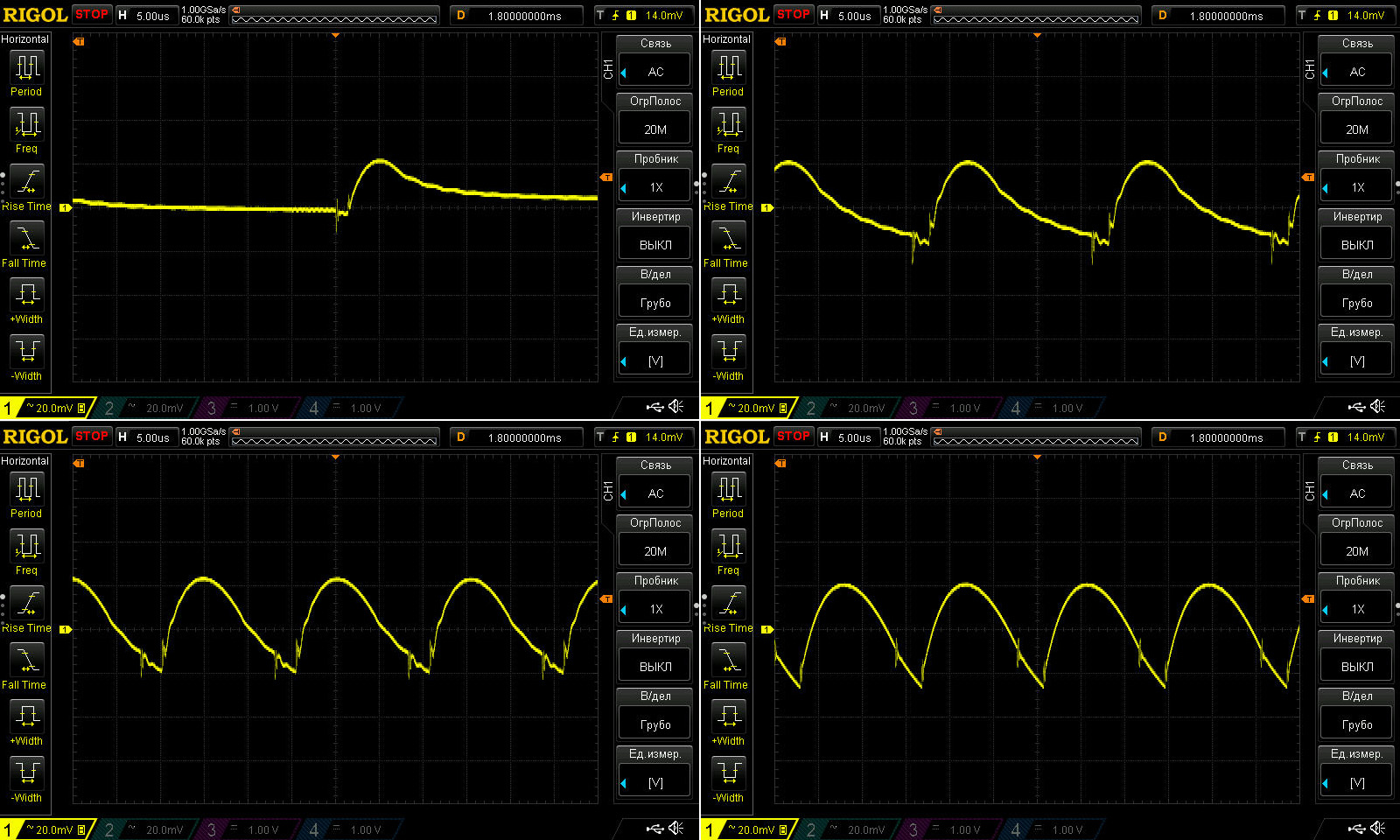
At low frequencies, I think it’s also excellent. The 100 Hz component is slightly visible, but at such a low level that you can simply ignore it.
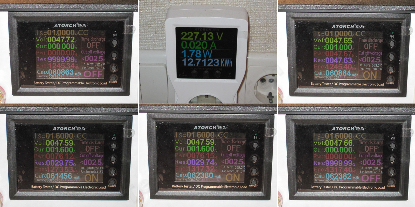
Load test.
1, 2. With no load, the output is 47.72 V, and power consumption is quite high at almost 2 W. That’s a lot. Apparently the manufacturer disabled the “green mode”; I can’t think of another explanation, although another possibility is that it uses some ancient controller, which seems much less likely.
3. Load current: 1 A
4, 5. Load current: 1.6 A, before and after warm-up
6. Warmed-up power supply with no load.
So what do we see? The output voltage drops by about 70 mV as the load increases, and also drops by 60 mV as the unit warms up. For a 48 V supply, that’s excellent.
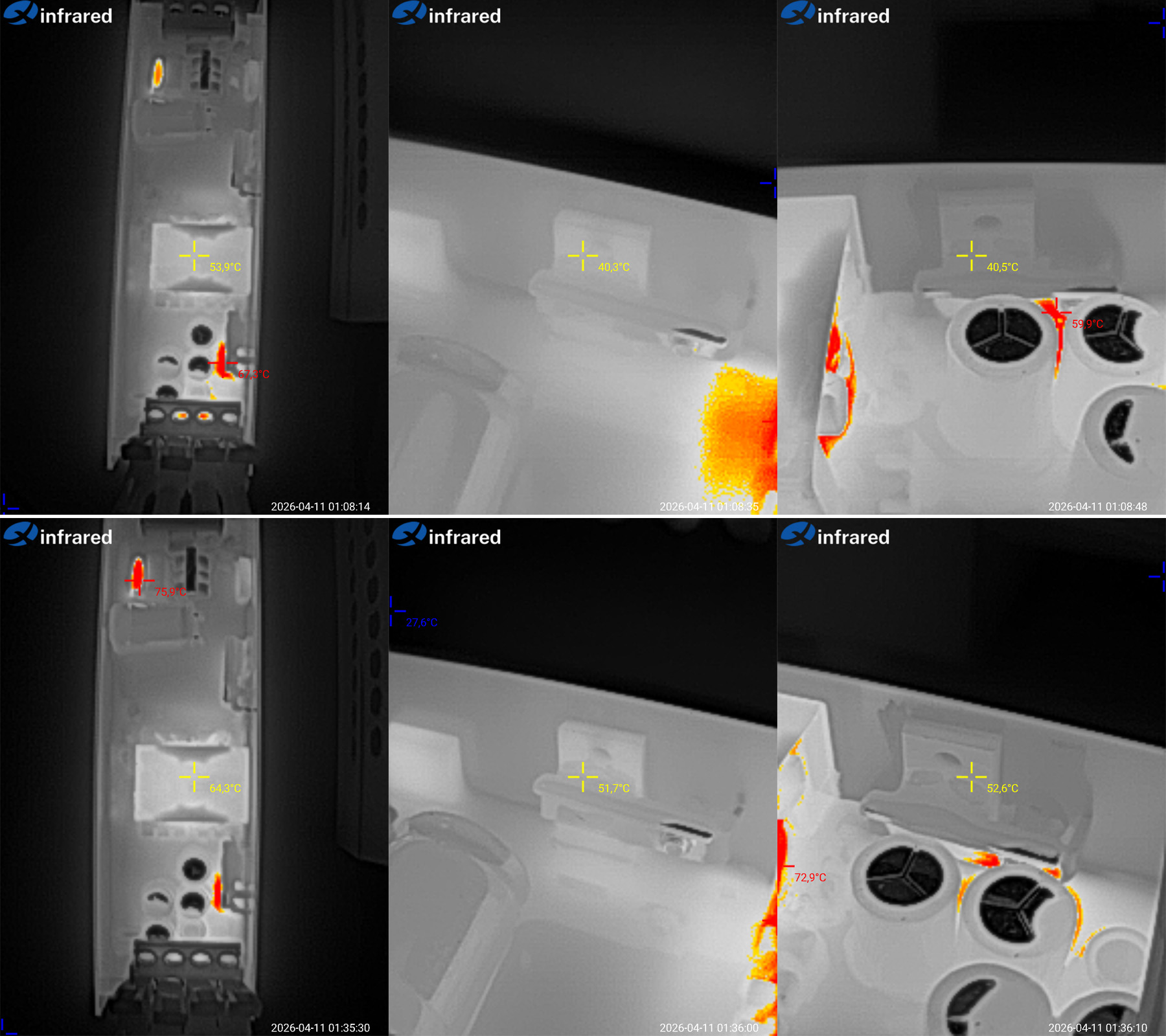
Temperature rise at 1 A and 1.6 A. I’ll only comment on the second case, since the first is laughably easy for this power supply.
In short: transformer, 64 °C; transistor, 52 °C; diode assembly, 53 °C.
This brought to mind a line from a movie: “You could work that thing to death.” Exactly. The temperatures aren’t just low; it feels like this power supply is running at about 50% of its rated power. The thermal headroom is enormous. For example, the transformer reached 64 °C in a room at 20 °C, so its temperature rise was 44 °C. Even with an ambient temperature of 50 °C, the transformer would still be at a reasonable temperature, not to mention the other components.
Second model: 48 V, 4.1 A, 200 W.
Dimensions: 193 × 48 × 29 mm. The only difference from the previous model is the length; this one is a couple of centimeters longer. Otherwise, they’re twins.
The topology is also unchanged; the manufacturer simply scaled up the previous model. Speaking of topology, both models use a flyback circuit. It can usually operate over a wide input voltage range, but since the input capacitor capacitance is often undersized, I recommend sticking to the 176–264 V range printed on the case.
1. The input has the same filter as the 100 W model, and it’s essentially faultless as well. The bridge rectifier is made up of two diodes connected in parallel.
2. There are now two 47 µF capacitors. I think that’s too little for the rated 200 W output, but let’s see what the tests show.
3. There’s one transistor, also pressed against the case with thermal paste.
4. But there are two output diode assemblies, while the filter capacitors are unchanged. In other words, they’ve simply added one diode assembly to the output stage.
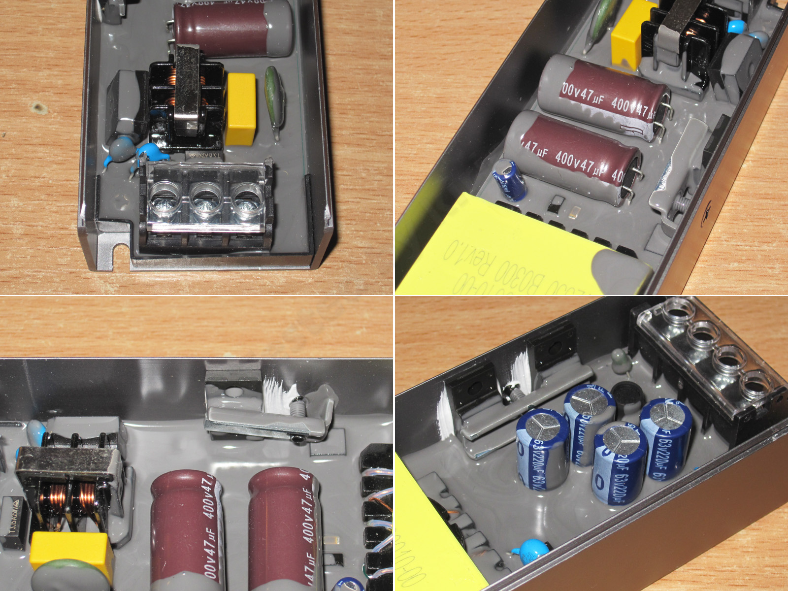
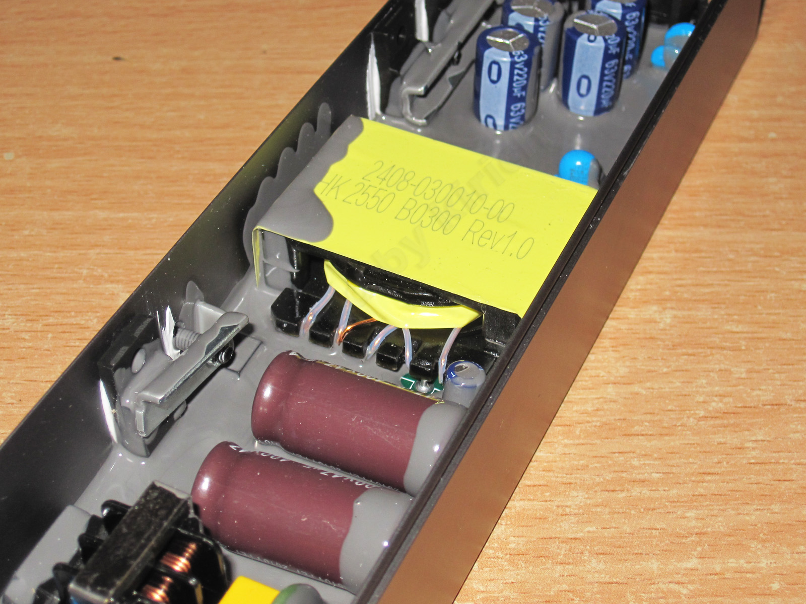
The transformer is just as nice-looking, although for some reason they used a very low-profile one here. There wasn’t much point, but it’s not a bad thing either.
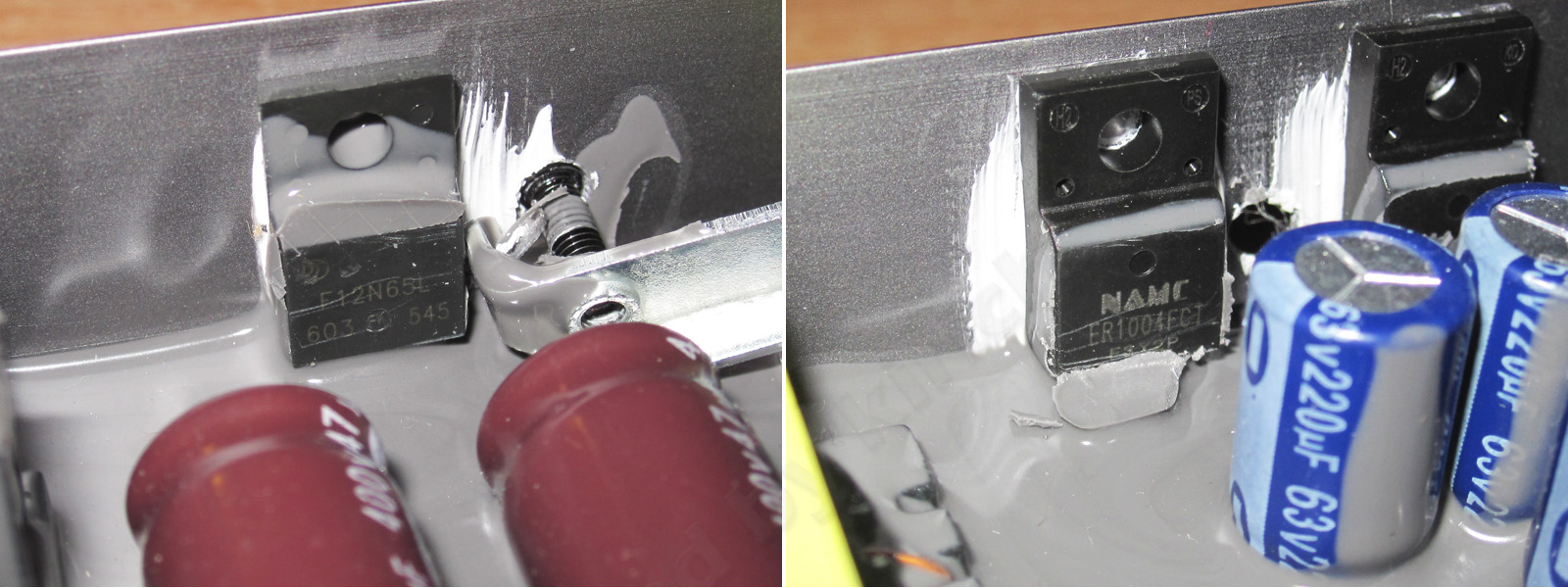
1. A high-voltage transistor rated for 12 A and 650 V—not bad at all. I assume they beefed up the control circuit too, but I can't see what's under the potting compound.
2. The diode assemblies are the same as in the previous model, so the headroom is just as good.
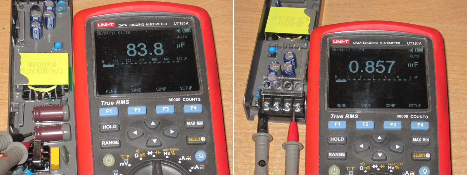
1. Well, everything is back to normal here. The input capacitors are rated at 47 µF each, so two should give 94 µF. In reality, it's about 84 µF, which is clearly too little for 200 W.
2. What's interesting is that the output uses the same capacitors as the 100 W model, from the same manufacturer and with the same capacitance. But there the total was 930 µF, while here it's about 860 µF. I can imagine that some of the power supply circuits affect the results, but I won't claim that for sure. In any case, in my opinion, that's a bit low for an output current of 4 A with this power supply topology.
The protection trip-point test revealed two things. First, the protection has a fixed threshold: increase the current just 10–20 mA above the limit and the power supply shuts down. Second, the protection actually trips at around 160 W, so this power supply is protected for roughly 140–150 W, not 200 W. I mentioned above that 84 µF is far too little for 200 W. It's still low for 150 W, but a little more manageable. In my opinion, a pair of capacitors from the 100 W model would be a better fit here.
Efficiency was measured from 0.3 to 3.3 A in 0.3 A increments and turned out to be pretty good, at around 88.5%. But most of the credit goes not to the designers, but to the relatively high output voltage, since efficiency usually drops as voltage goes down.
With no load, the output is about 47.69 V and power consumption is 0.7–0.75 W, noticeably lower than the 100 W version.
High-frequency ripple with no load and at currents of 1.1, 2.2 and 3.3 A. It's essentially not much higher than on the 100 W version. At maximum current, I measured about 60 mV, which is excellent.
The low-frequency ripple is more odd than large. The peak-to-peak value was about 200 mV, and at 2.2 A it was slightly higher than at 3.3 A.
At one point I thought it was a glitch in the electronic load, but trying ordinary resistors made absolutely no difference. I suspect this is a quirk of the PWM controller, compounded by the rather low input capacitance.
In any case, this ripple isn't critical for the load. Given the 48 V output, it works out to just 50 mV when scaled to a typical 12 V power supply.
Load tests.
1. Cold power supply, no load.
2. Cold power supply, 2 A load.
3. Warm power supply, 2.6 A load.
4. Warmed-up power supply, 3.3 A load—in other words, essentially maximum load.
5. Hot power supply, 3.3 A load.
6. Hot power supply, no load.
The test results show a fairly large negative relationship between output voltage and load, about 1.3 V. That's a little surprising; temperature only changes the voltage by 20–30 mV.
It's still odd that the output voltage sags so much, even though I wouldn't call the current particularly high. Usually this isn't critical for the load and is well within the standards, but it's still puzzling.
Temperature of the main components at currents of 2, 2.6 and 3.3 A.
2 A — transformer 58.6 °C, transistor 45.6 °C, diode assemblies 48 °C.
2.6 A — transformer 68 °C, transistor 56 °C, diode assemblies also 56 °C.
3.3 A — transformer 78 °C, transistor 61 °C, diode assemblies 66 °C.
In my opinion, these are very good results. The room was cool, though—about 20 °C. The heating pipes were off, and the heating outside hadn't been turned on yet :( Still, I think the power supply can easily handle its rated 150 W with some headroom, at an ambient temperature of around 40 °C.
The third model in this form factor: 48 V, 8.3 A, or a whole (not necessarily) 400 W.
This one is a bit larger at 229 × 59 × 29 mm; the only dimension unchanged from the previous models is the height of 29 mm.
I could say this is just a larger version of the previous models, but it isn't: it uses a completely different topology, a half-bridge converter, which is typical for power supplies in this power range. Though to be fair, they do have a lot in common.
And for comparison, here's a photo of all three models disassembled.
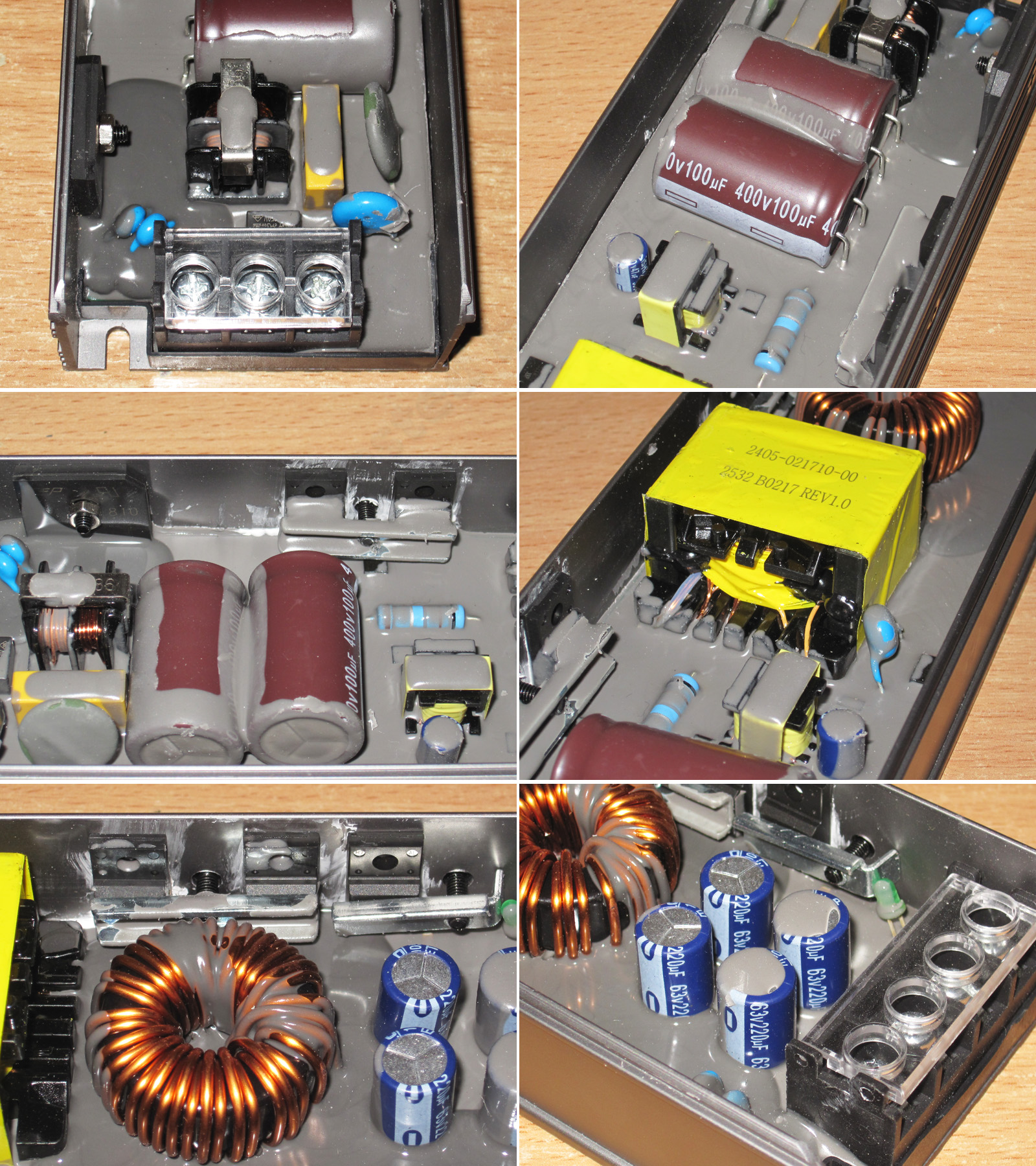
1. The input filter is almost the same as on the previous models, but they've added a varistor.
2. The input capacitors are rated at 100 µF each, for a total of 200 µF, and once again, the tiger isn't getting enough meat. I didn't check the brand, but the PWM controller's supply capacitor is a name-brand Aishi.
3. The diode bridge is bolted to the case. I didn’t check whether there’s thermal paste under it, but there definitely is some under the high-voltage transistors.
4. The transformer is a little larger than the one in the 200 W version, but that’s fine: with this topology, it can deliver more power than the earlier models while staying about the same size.
5. There are no fewer than three output diode assemblies. Next to them is the output filter inductor. It looks very neat, though that’s true of all three models.
6. There are also four 220 µF output capacitors. That’s acceptable here, and as for the lack of an inductor, we’ll check the ripple later.
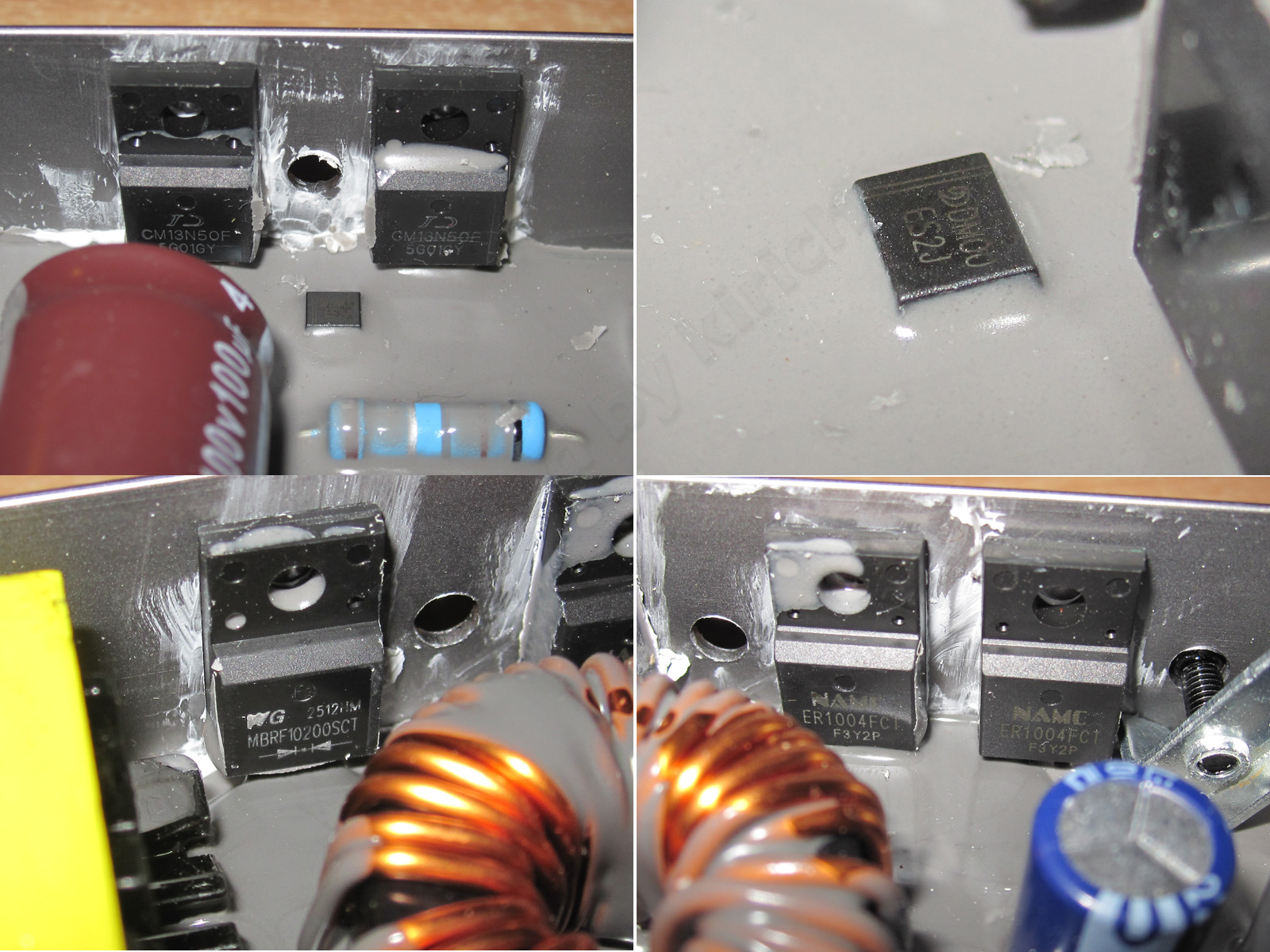
1. The high-voltage transistors come in a pair because of the topology. They’re rated for 13 A and 500 V, which is perfectly fine.
2. Something was sticking out of the potting compound nearby. I thought it was the PWM controller, but it turned out to be just a diode.
3, 4. The diode assemblies are different: one is a 10 A, 200 V Schottky, and the other is a pair of ER1004FCTs, like in the previous models. Don’t be surprised: this isn’t a case of “whatever they found on the floor, they slapped in.” It’s perfectly normal, because the output diodes here work in two circuits, roughly speaking, an upper and a lower one, and the requirements differ.
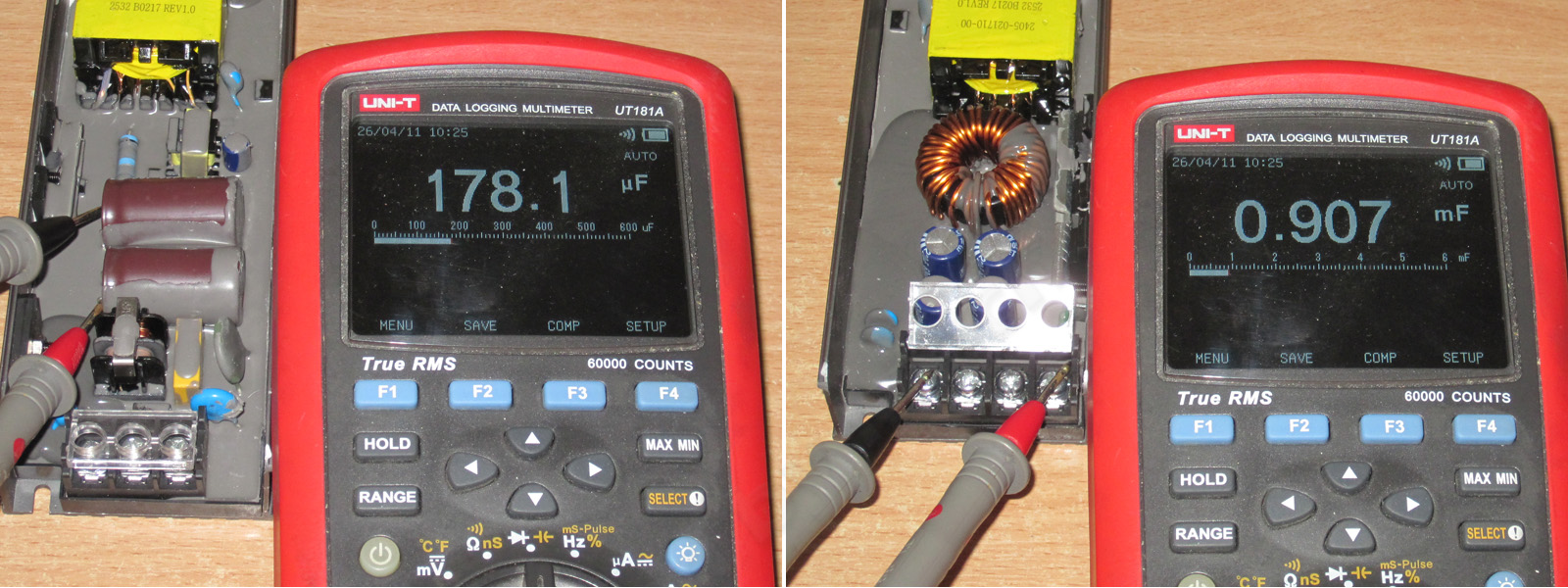
1. The measured input filter capacitance is about 180 µF, which is low again. Still, it’s nice that the stated capacitance is almost exactly what I measured.
2. The total output capacitance is 907 µF, which is fine.
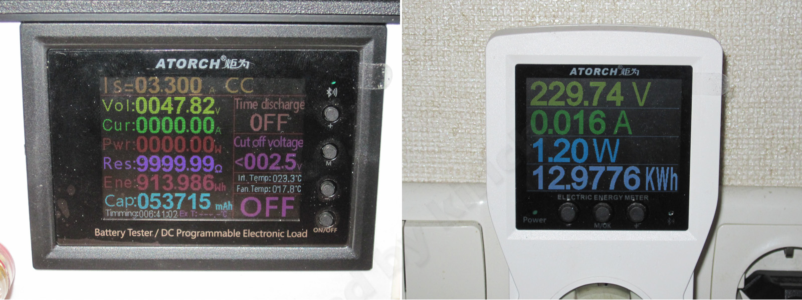
With no load, the output is 47.82 V and power consumption is 1.2 W, which is perfectly normal for a power supply of this rating.
The maximum current I could get without the voltage dropping was about 6.6 A. At 6.7 A it starts to drop gradually, and at 6.9 A the output is already down to about 41 V.
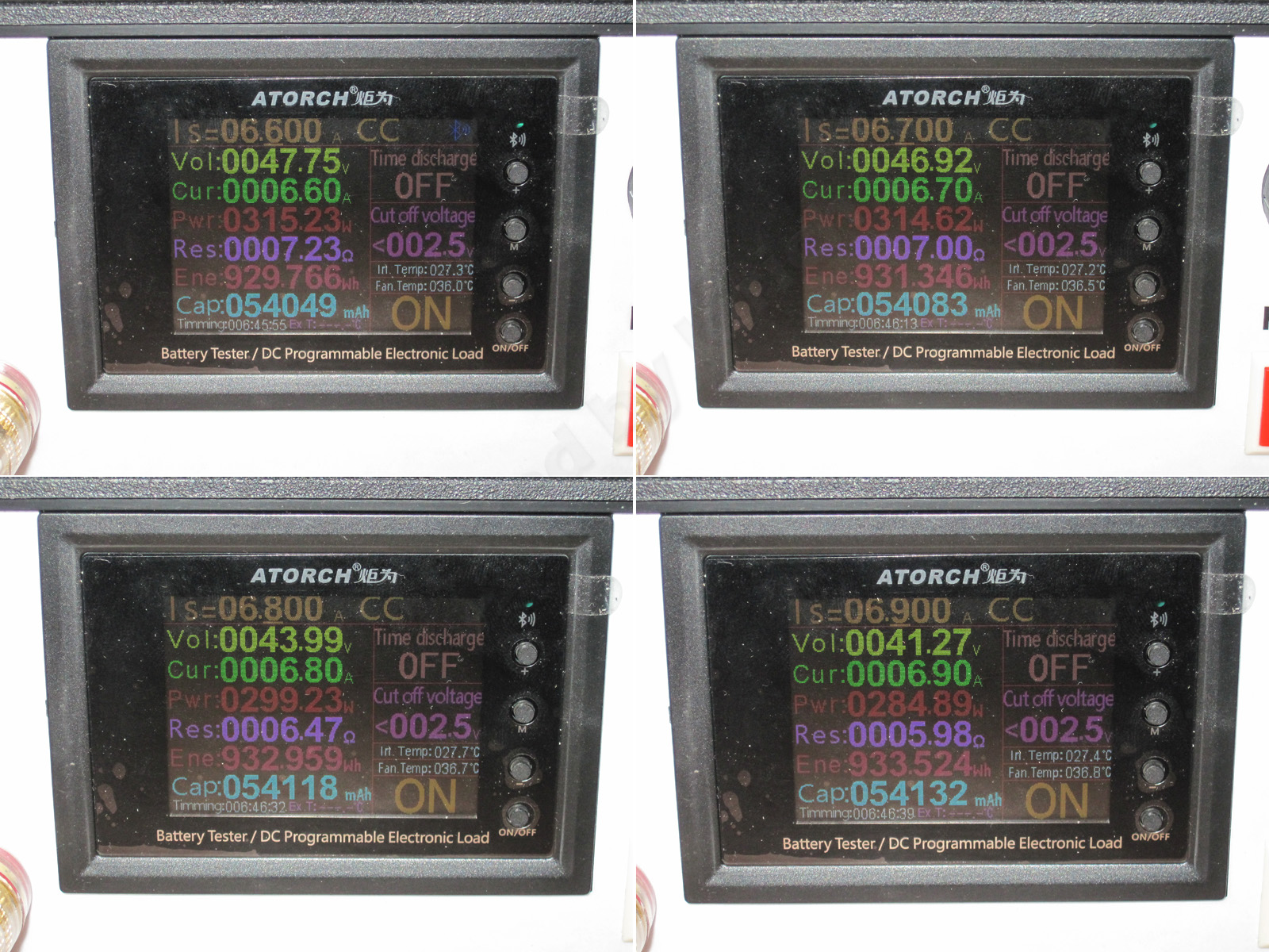
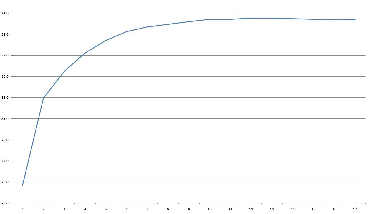
I measured efficiency from 0.4 to 6.8 A in 0.4 A increments, and it came out at around 90%. That’s not bad, but with this topology and output voltage I expected 91–92%. Still, 90% is pretty good.
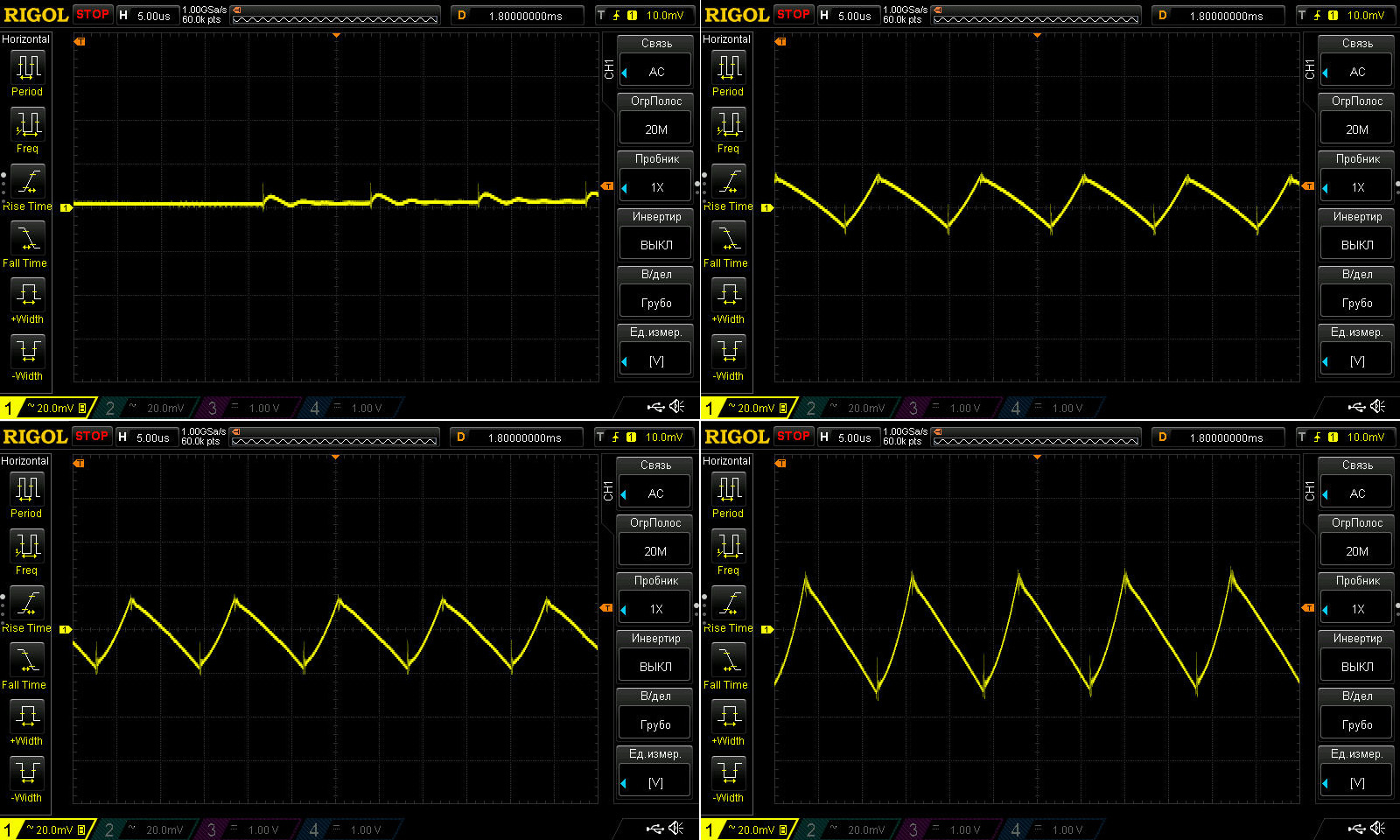
Ripple with no load and at currents of 2, 4, and 6.5 A.
And here everything looks great: 48 V, 300 W output, no filter, and just 50–60 mV of ripple. What’s not to like?
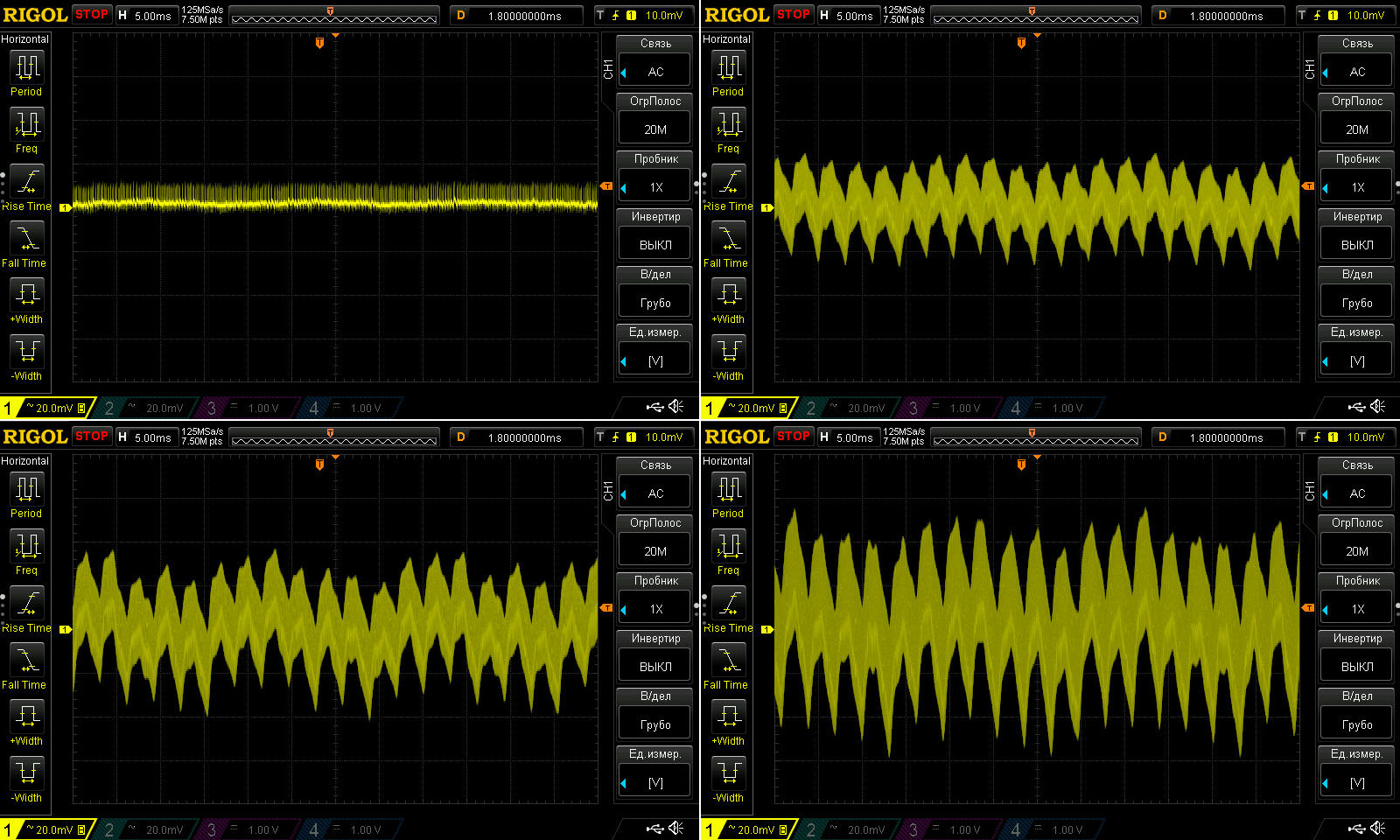
I accidentally captured this waveform with a 5 ms timebase instead of 10 ms, as usual, but it doesn’t really change the picture: there’s noticeable ripple.
And it’s not about the amplitude, which is excellent at just 100 mV, but about the waveform, so to speak. There’s a big difference between 100 mV of overall noise with 50 mV spikes on top, and 20 mV of average noise with spikes reaching 100 mV.
So here the overall amplitude is low, which is very good, but I personally don’t like the shape of the ripple. It may be a characteristic of this design, but I don’t really feel like investigating further.
Warm-up test:
1. Cold power supply, no load
2. Cold power supply, 3 A load
3. Warm power supply, 4.5 A load
4. Fully warmed-up power supply, 6.5 A load.
5, 6. During the test I had to reduce the current to 6 A, so these are the results for the hot power supply at 6 A and with no load.
The voltage barely depends on the current: 40 mV against 48 V is less than one-thousandth. The temperature-related voltage change is comparable, at just 50 mV. So there are no complaints here at all. It’s even strange that one factory makes two similar power supplies, yet the 200 W model has a 1.2 V difference while the 400 W model has just 40 mV....
As I mentioned, during testing the voltage dropped at 6.5 A, apparently because the protection kicked in, either due to temperature or a change in the shunt—I can’t say for sure, but it happened. I first reduced the current to 6.1 A, then decided to lower it to 6 A, and that was the right call: it turned out that 6 A is about the limit for the warmed-up power supply. Even at that current, the voltage would sometimes fluctuate, though only slightly.
As for temperatures, first, here are the results at 3 A. There’s not much to comment on: everything is almost cold.
Now at 4.5 and 6 A. The power supply was first warmed up at 6.5 A and then tested at 6 A, but I don’t think that makes a difference.
4.5 A — transformer: 72 °C, transistors: 58 °C, diodes: 60 °C, output inductor: 66 °C. In each case, I measured the hottest spot.
6 A — transformer: 90 °C, transistors: 75 °C, diodes: 74 °C, output inductor: 85 °C.
Based on the results, I’d say 6 A, or 285 W, is too much for it. This is especially evident in the transformer temperature. In my opinion, the power supply’s actual rating is closer to 250 W.
And now we’re gradually getting to much more interesting specimens. When someone first sent me photos of these, the first thing I said was that they looked an awful lot like laptop batteries—if you cut off those pig-tail wires, of course. Otherwise, they’re almost identical.
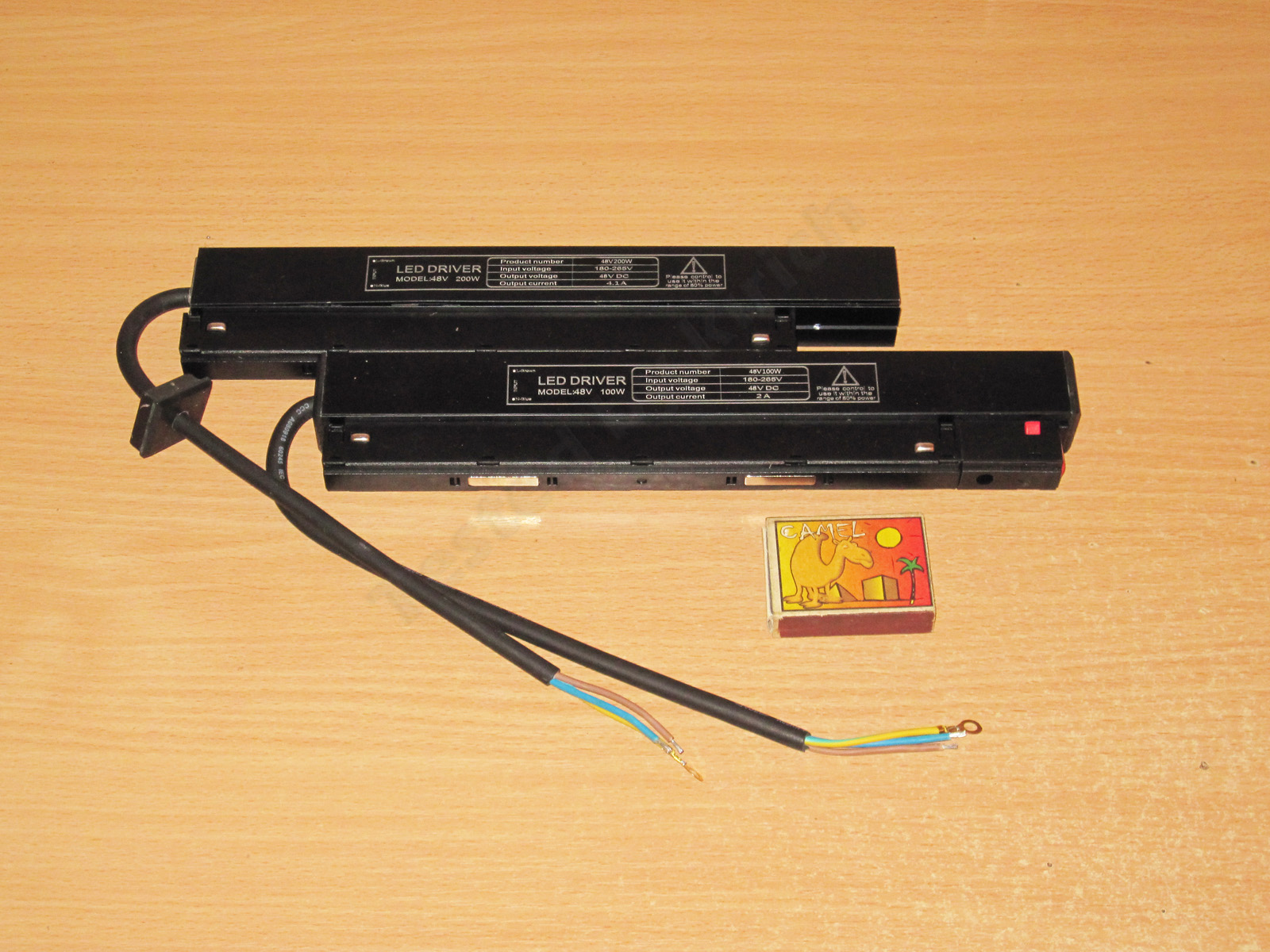
A quick note about the labeling. The cases are marked “LED Driver,” which is completely wrong: a “driver” and a power supply are absolutely not the same thing.
An LED driver is specified by its output current, which it regulates, and the output voltage range over which it maintains that current. You can’t substitute one for the other in any combination, because a driver usually outputs a little more than its stated maximum, while a power supply does not regulate current.
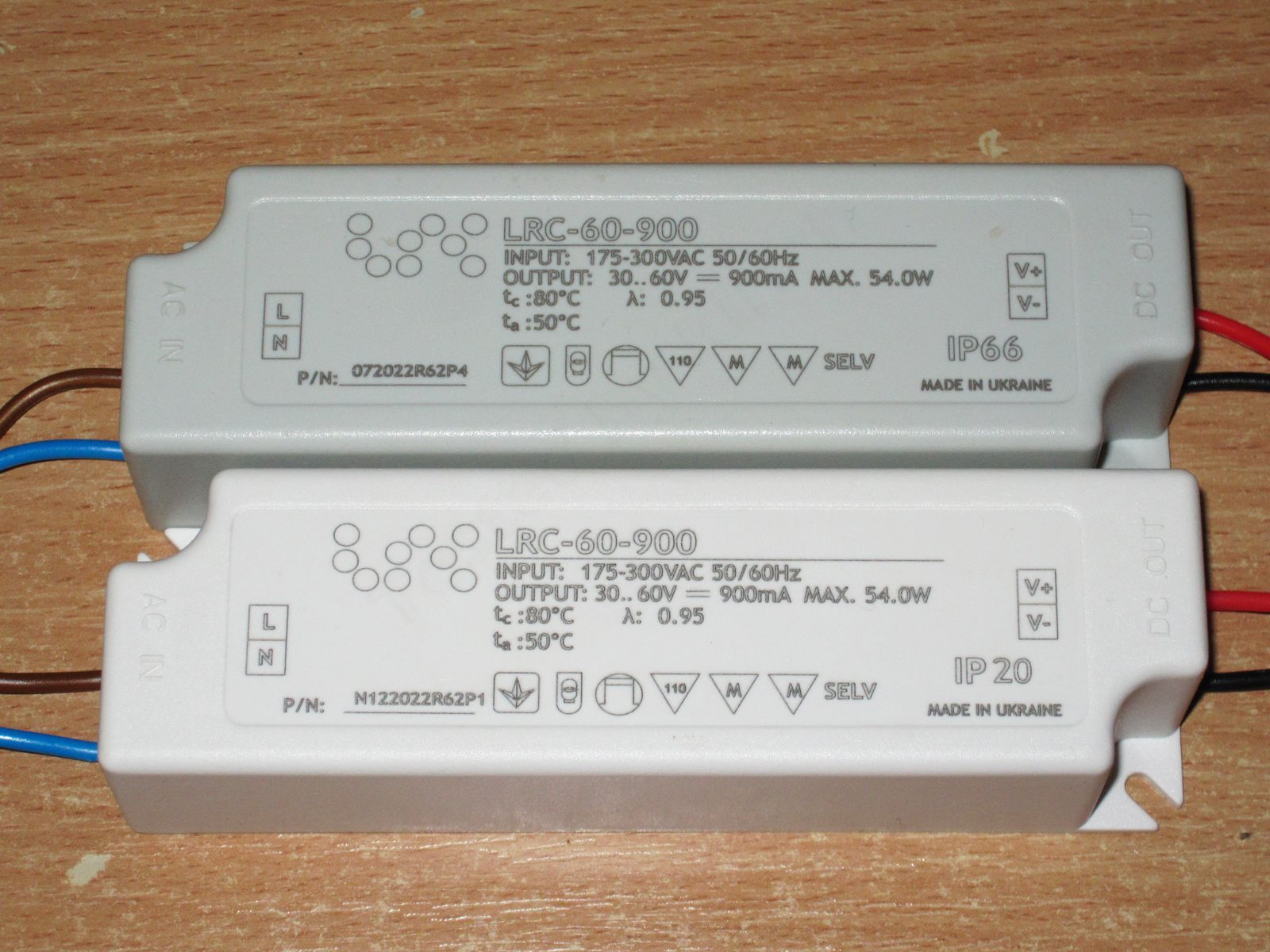
They’re practically identical in construction, but I think that’s down to their intended use. As I understand it, these are power supplies for track lights. There are a couple of magnets on top and two spring-loaded contacts on each side, but power is connected to only one pair, with the same polarity, naturally.
The housing is a U-shaped aluminum profile with a cover. A roughly similar-sized plastic piece with clips and catches is screwed onto it.
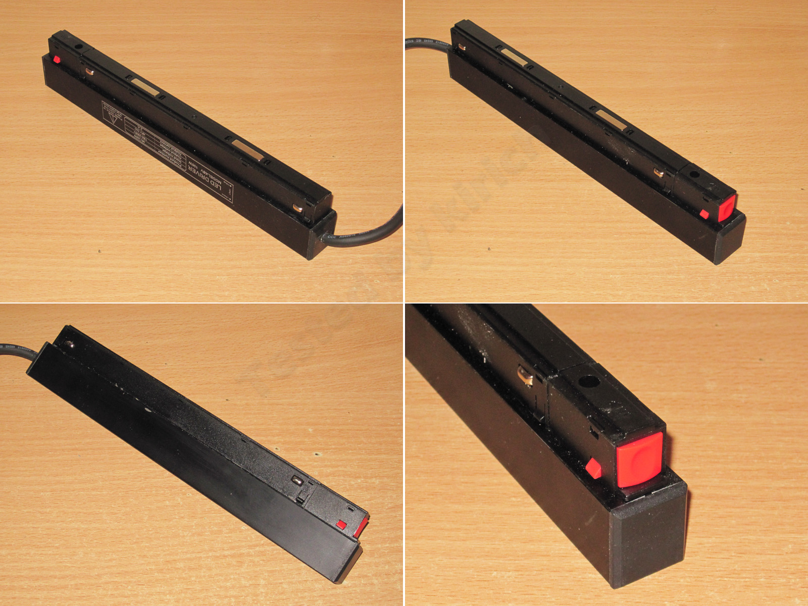
1. The output wires come out at one end. The powered and unpowered contacts are also mounted at different heights, so nothing gets burned if the unit is installed incorrectly.
2. The contacts are spring-loaded. The soldering gets a C-minus; you can tell they’ve cut a few corners.
3. The inside is potted with compound, mostly for electrical safety and heat dissipation, I think, rather than waterproofing. Either way, it’s a plus.
4. The input wires are tinned, and the ground wire has a ring terminal.
The 100 W version measures 252 × 45 × 22 mm.
For testing, I again used a 1200 W load based on the DL24MP, connected with four wires right up to the output terminals. That’s the right way to do it, since there’s no way to eliminate the internal wires anyway.
First up are the tests of the 100 W model: 48 V, 2.1 A.
The protection is set very roughly and trips at around 3.5 A, which is far too high for a power supply like this—especially since the load is an LED strip, which fundamentally has no such thing as inrush current.
I measured efficiency over a range of 0.2–2.5 A, in 0.2 A increments (the final step was in 0.1 A increments), and got about 87%.
With no load, the output is 47.93 V and power consumption is about 0.2 W, which is pretty good.
Ripple is noticeably worse than on the previous models. That’s understandable: fitting enough capacitance and filtering into such a compact package isn’t easy, though it’s certainly possible. Maybe they just cut costs.
Below are the results with no load and at currents of 0.7, 1.4, and 2.1 A. At maximum power, I measured around 600–800 mV. If this were a 12 V power supply, I’d probably complain, but here it’s an acceptable result: tolerances increase with voltage, so for a 12 V version this would be equivalent to 150–200 mV.
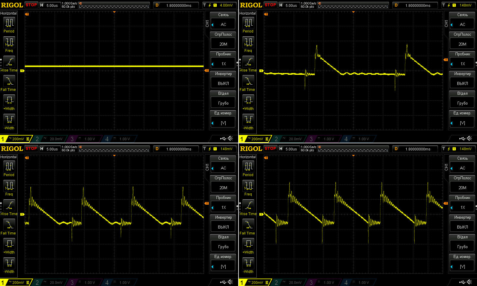
At the low frequency, you can see the “green mode” in action. But I should point out that the 100 Hz ripple itself isn’t all that large. The overall ripple amplitude has barely changed, by the way.
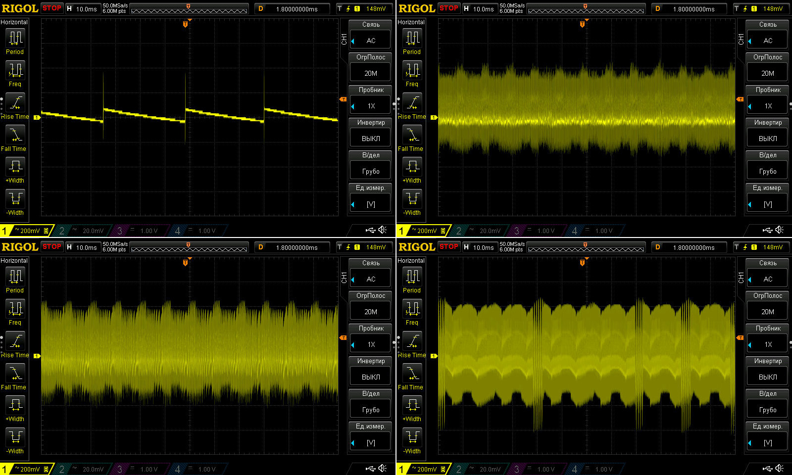
Something else puzzled me a little. It’s not really important, but I couldn’t help noticing it. At high power, even a small change in load current noticeably changes the ripple pattern.
Here are some example waveforms at 1.7, 1.9, 2, and 2.1 A.
The temperature test was done with the case closed and potted. Here are the intermediate measurements:
1. Cold power supply, no load
2. Cold power supply, 1 A load
3. Warm power supply, 1.5 A load
4. Heated-up power supply, 2 A load
5. Hot power supply, 2 A load
6. Hot power supply, no load.
Several things are immediately apparent here:
1. The voltage increases with load current: the higher the current, the higher the voltage. In my cold tests, I measured 47.96 V at 0.2 A and 48.16 V at 2.3 A. The difference is absolutely insignificant, but it’s quite possible that the voltage is regulated on the primary side here.
2. Based on these tests, the voltage variation with load came out to 70 mV.
3. The voltage varied a little more with temperature, by about 110 mV.
Overall, the results are quite respectable.
Case temperature at 1, 1.5 and 2 A. The thermal camera does record the maximum temperature, but the readings are barely visible in the photos.
Depending on the current, the temperature was 37.8, 49 and 58 degrees, which is perfectly normal. Besides, since the unit is potted, there are unlikely to be any localized hot spots inside.
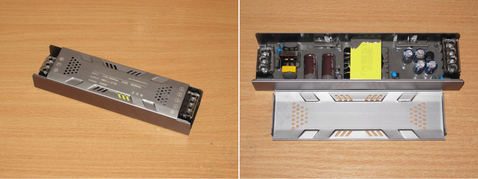
The second unit is twice as powerful, at 200 W. Interestingly, it's even a little smaller—or, more precisely, a little shorter.
For comparison, the dimensions of both units:
100 W - 252x45x22 mm
200 W - 245x45x22 mm
The 200 W model in the photo is missing one end cap and the button retainer. I found them later in the box, since it arrived disassembled, but the dimensions listed are correct.
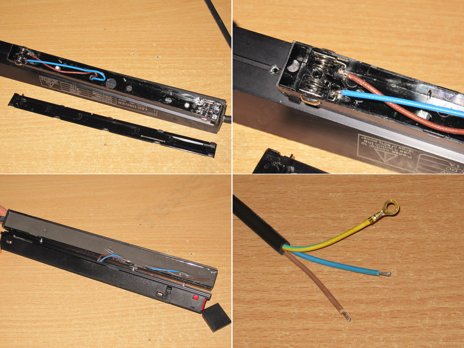
The potting here is less thorough, so you can make out some of the components and see that the board is noticeably shorter than the case.
At this point, I thought this was yet another Chinese 100,500-watt PMPO power supply—the internals looked downright ridiculous.
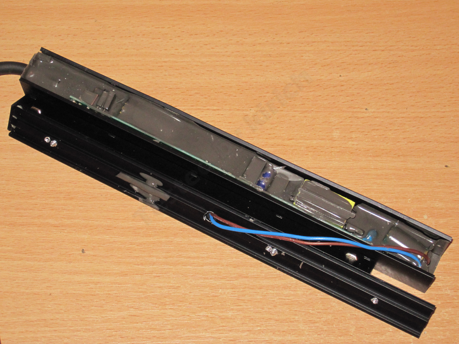
Right away, I noticed the odd self-tapping screws driven straight through the cover. Not only had they clearly missed on the first try, judging by the two holes for each screw, but one of them had gone in literally a millimeter from the transformer. Any closer and it would have cracked the core.
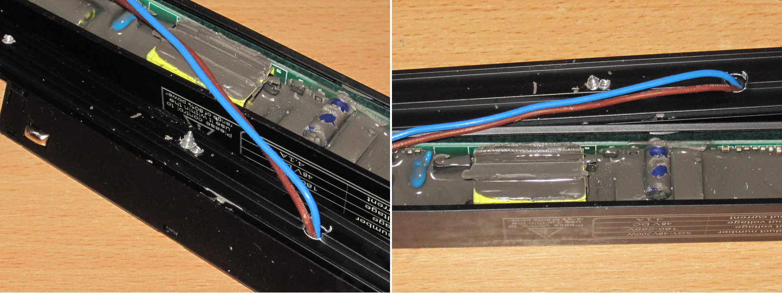
On the input side, you can see an X capacitor, two bridge rectifiers, a fuse and the input capacitor. Judging by its appearance, I doubt it's larger than 68 µF—maybe 82 µF.
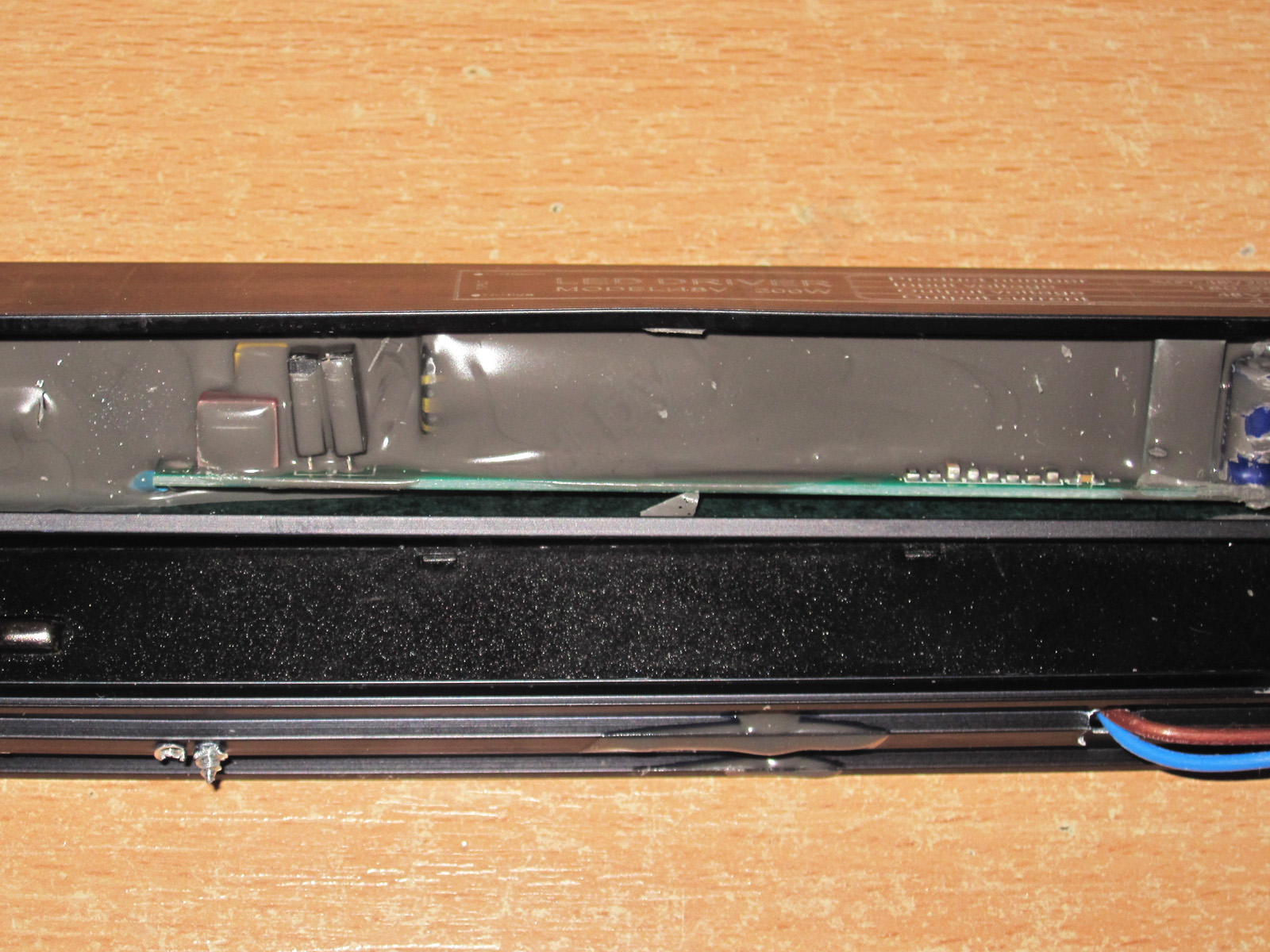
The transformer looks ridiculously tiny for 200 W. To its right are the feedback optocoupler and a Y capacitor, and farther right is the output capacitor, which I have a serious issue with: it's rated for 50 V, but for 48 V you should use capacitors rated for at least 63 V, as in the previous models.
It's hard to make out, but the safety looks at least adequate, if not excellent. The potting helps, too.
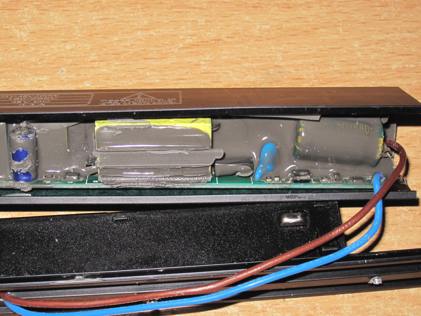
I also noticed that although the board is relatively far from the case, some component leads stick out. I was about to criticize it, but then I saw that the side wall of the case is lined with electrical insulating paper, so it's all fine here. And remember, this power supply is intended to be grounded.
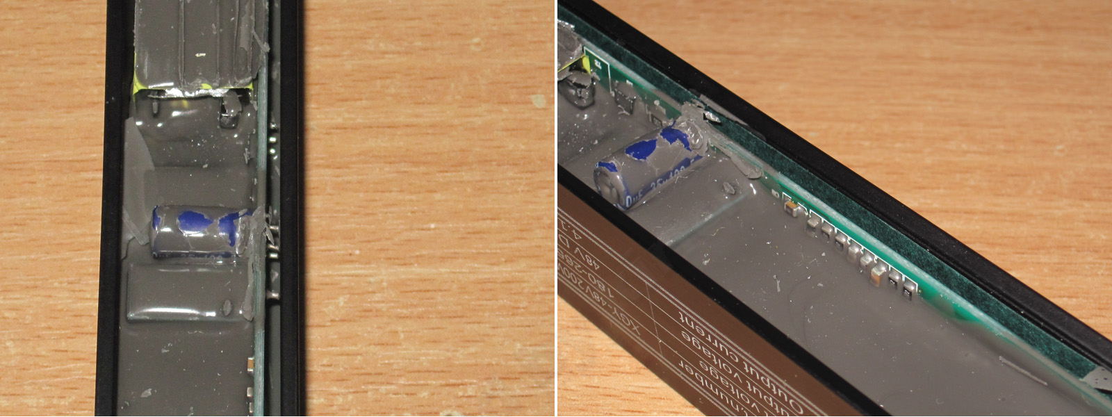
Here the overcurrent protection is set correctly. The unit still works normally at around 4.5 A, and starts dropping the voltage at 4.6 A, so the maximum output power is about 215–220 W.
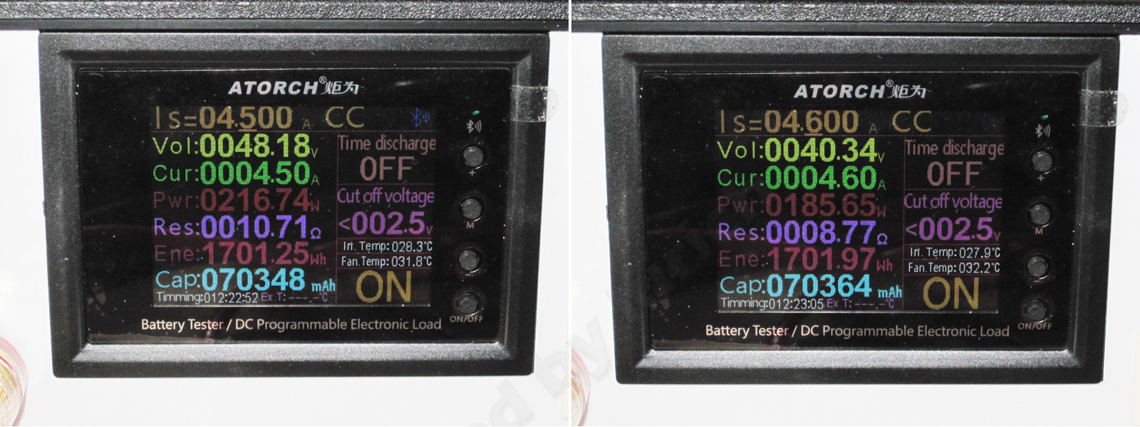
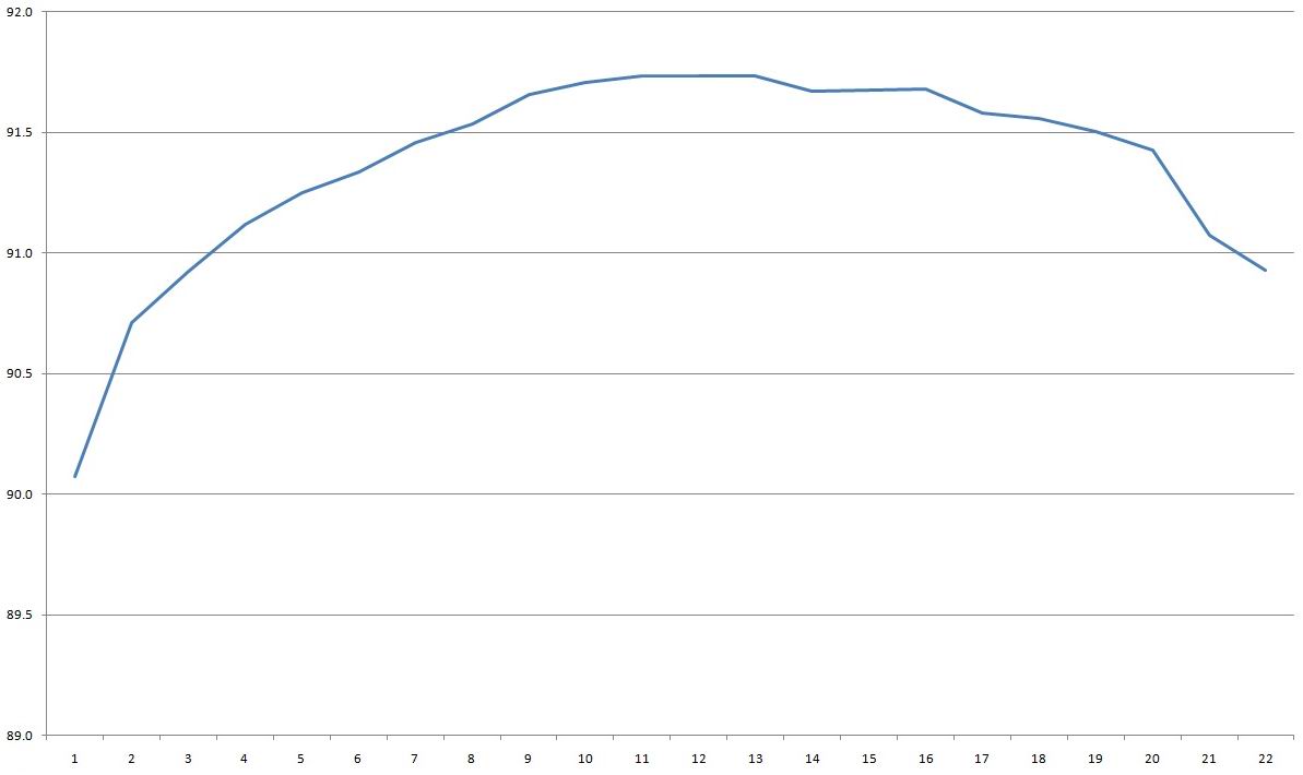
Efficiency was measured from 0.2 to 4.4 A and came in above 91%, which is very good for such a compact unit.
With no load, the output is 48.2 V and power consumption is about 0.6 W. No complaints at all.
The ripple wasn't quite as good here as I'd hoped, either. I checked it with no load and at 1.4, 2.8 and 4.2 A.
At high frequency, there's basically nothing to complain about: 100 mV at maximum load is genuinely great. But that odd waveform with no load immediately raised a red flag.
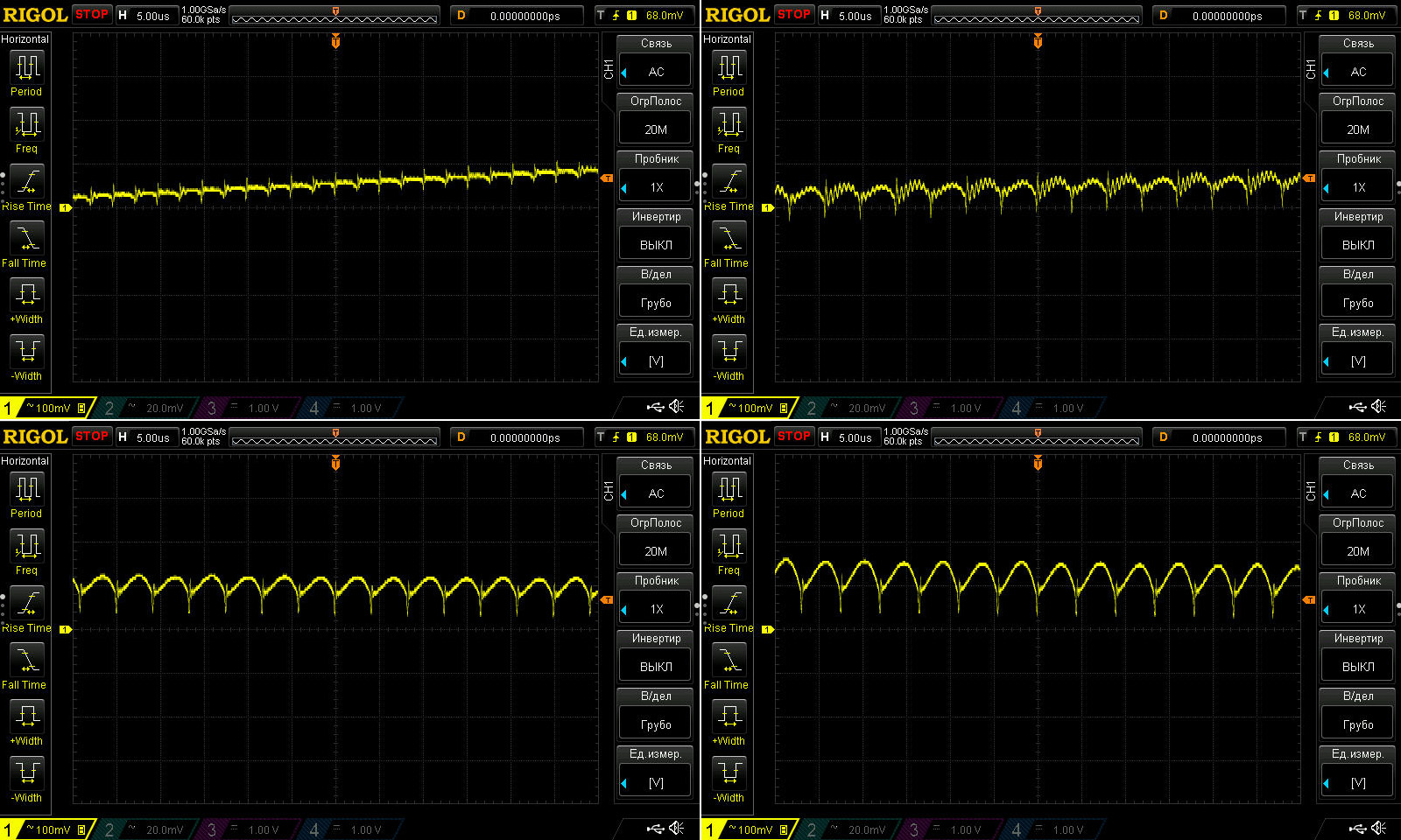
And now at low frequency.
The explanation for the “crooked” high-frequency waveform was immediately apparent: it's simply the characteristic behavior of “green mode.” Everything is fine.
Under load, though, the waveform looks worse. I even got the impression that there's no input capacitor at all, because the middle section of the waveform—the part where 100 Hz spikes usually appear—is completely absent. Instead, there are clear 100 Hz ripples at the output, with a full amplitude of 1.2 V.
Well, 1.2 V isn't that bad against 48 V, but the point is that if you power an LED strip with this supply, those 100 Hz ripples could cause some flicker, unlike the high-frequency ripple, which is practically perfect here.
I'll think about it some more, but I'd like to take this unit apart to find out whether I'm right that the input capacitor is either open-circuit or disconnected. It clearly isn't a matter of capacitance, since the ripple is present even at low current. Or perhaps this is a very characteristic behavior of the PWM controller; that's theoretically possible, too.
And now for the most interesting part: the warm-up test. This is a test of a very compact power supply rated at 200 W!
1. With no load and the unit cold, we get 48.23 V.
2. Cold, at 2.5 A
3. Then at 3 A
4. Warm, at 3.5 A
5. Warmed up at a current of 4.1 A.
6, 7. With the unit thoroughly warmed up, I first raised the current to 4.4 A, but took pity on it and eventually lowered it to 4.3 A.
8, 9. The warmed-up unit at 4.3 A and with no load.
Overall, I can say that the output voltage barely depends on the load: just 50 mV. This may simply be due to voltage drop in the output wires leading to the terminals. After warming up, the voltage rose by 120 mV, which is also a very good result, especially considering the output voltage.
And here are the temperature measurements.
First, a quick look at 2.5, 3, and 3.5 A.
2.5 A — Around the input capacitor: 44°C; transformer: 58°C; side panel: 40°C.
3 A — 56°C, 68°C, and 50°C, respectively.
3.5 A — Likewise, 61°C, 75°C, and 54°C.
So far, no complaints at all. The power supply handles a 170 W load with ease. The hottest part is the transformer, but 75°C is a normal operating temperature, especially since I was essentially measuring the winding temperature; the core is usually cooler.
Now things get more interesting: currents of 4.1 and 4.3 A.
4.1 A — Around the input capacitor: 68°C; transformer: 83°C; side panel: 59°C; input diode bridges: 75°C.
4.3 A — Around the capacitor: about 74°C; transformer: 87°C; side panel: 62°C; diode bridges: 79°C.
I take my hat off to it. I wasn't sure the power supply could deliver the claimed 200 W—or, more precisely, 4.1 A. In practice, it performed excellently even at 4.3 A, delivering 208 W, or about 104% of its rated load. I think it uses a decent circuit design, and the potting compound also played an important role by spreading the heat to the case and preventing localized overheating.
This power supply turned out to be very convenient for testing: it is potted, and you can measure the transformer temperature.
Conclusions, in the same order as the models tested
100 W — Overall, I liked it: quality construction, potting, low temperatures. There’s basically nothing to complain about. Actually, no, there is. This is an honest 100 W power supply with an honest 100 W rating, but its protection is throttled, limiting you to no more than 80 W. Seriously, that’s a very strange and unusual choice. We’ve seen all kinds of power supplies, but it’s extremely rare for a manufacturer to cut the power back so drastically themselves. Mark it as a 75 W unit and you’ve got an excellent power supply with plenty of reliability margin. That’s a fact.
200 W — The situation is somewhat similar to the 100 W model. The claimed 200 W would be very close to the actual maximum, so perhaps this really is a 200 W unit, albeit one running right at its limit. Its protection is also throttled, kicking in at around 150–160 W, which I consider its true continuous power rating. In other words, mark it as 150 W and you get the actual power, neat construction, decent components, and a perfectly reasonable service life. The only thing I’d improve is the input capacitor capacity: increase it at least a little, from 84 to, say, 120 µF.
400 W — Much of the above applies here too: the actual limit is noticeably lower than the claimed rating, the components are decent, and the input capacitor capacity is also on the low side. But unlike the previous models, 400 W would overload this one, so the current limit of 300–310 W seems entirely justified. I recommend keeping the continuous load to no more than 250 W. And at that load, an input capacitor capacity of 180 µF seems perfectly acceptable. So yes, it’s a great unit, but relabel it as 250 W and that would be both honest and accurate. One plus is that it seems to have thermal protection, at least the protection threshold clearly depends on temperature.
100 W track-mounted — It would be a good power supply with an honest rating, and I could recommend it if not for at least one issue: the protection current is set much too high. It might handle 3–3.4 A continuously, but I wouldn’t risk it. Otherwise, it caught my interest: it has very good potential and delivers its rated power.
200 W track-mounted — This power supply is both great and bad. I really liked not only its actual output power, but also its stable operation, low high-frequency ripple, and well-set protection threshold. If it weren’t for the odd 100 Hz ripple, I might say this is exactly what an honest, high-quality power supply should look like. But besides the 100 Hz ripple (which may be a defect in this particular unit), I have a major concern about the output capacitor: it’s rated for 50 V, and that’s not acceptable. It should be at least 63 V! I suspect the 100 W version has the same issue.
Now, briefly.
The first three are good power supplies, with good construction and components and reasonable temperatures. But all three have lower actual output power than claimed. For the 100 W and 200 W models, that’s more of a feature; for the 400 W version, it’s a bug, because at 400 W it would simply overheat. Sure, you could sell it as a 400 W unit with protection at 300 W and an actual rating of 250 W, but I think it’s simpler to label it as 250 W from the start and save both the customer and yourself the confusion. Strictly speaking, the correct figures would be 75-150-250, not 100-200-400.
As for the two track lights, they turned out better than I initially thought. At least, I have no complaints about their power output or heating. The first one has an issue with the protection current, while the second has problems with ripple and the output capacitor. Otherwise, they're great power supplies.
That's all for now. I hope you found this useful and interesting, and of course, thanks to Vitaly for sending the samples for testing.
This model is included in the summary table: Comparison of power supplies: ripple, efficiency, and temperature rise
The figures from this review are in the measurement database: Power supplies
Calculate manuallyAll calculators
Discounted products
You may be interested in



Discounted products
Support the project
All the content on the site and the advice are free, but we’d be grateful for your support of the project and the channel!
Discuss on the forumHave a question or some experience to share? Discuss the article with the author and readers: the forum is a convenient place to share schematics and photos.
Go to the forumOnly registered readers can comment. It takes a minute to sign up, and you can log in with the same account you use on the forum.
Log inRegister