
Mean Well LRS-50-12 power supply
660₴
A reminder: to keep up with new posts on the blog, I recommend following me on Instagram, where I'll post notifications about all new topics and maybe write about something interesting too - link to the account
You can also subscribe to updates and new articles on the Telegram channel - https://t.me/KirichBlog
I bought it as part of a large group order, and not just one unit, so it came to 572 UAH rather than the 660 UAH listed in the title. I could have looked around at other stores, but that would have meant another 70 UAH for shipping, so the total would have worked out about the same.
The only thing is, I use 15 V power supplies for my project, but the closest available model was 12 V. More on that at the end of the review.
The packaging is typical for Mean Well: a cardboard box with a window.
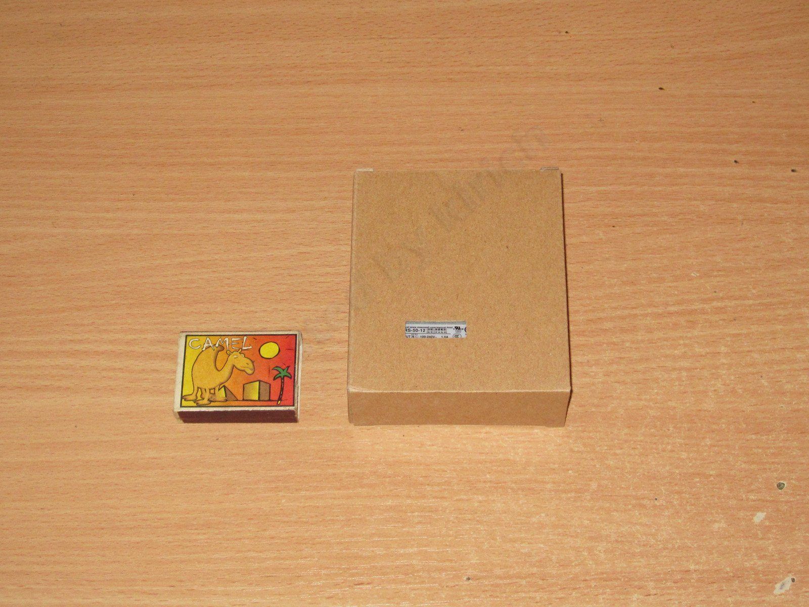
As you'd expect, there's a datasheet - link.
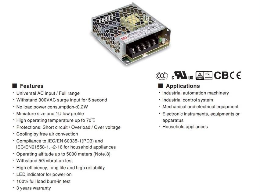
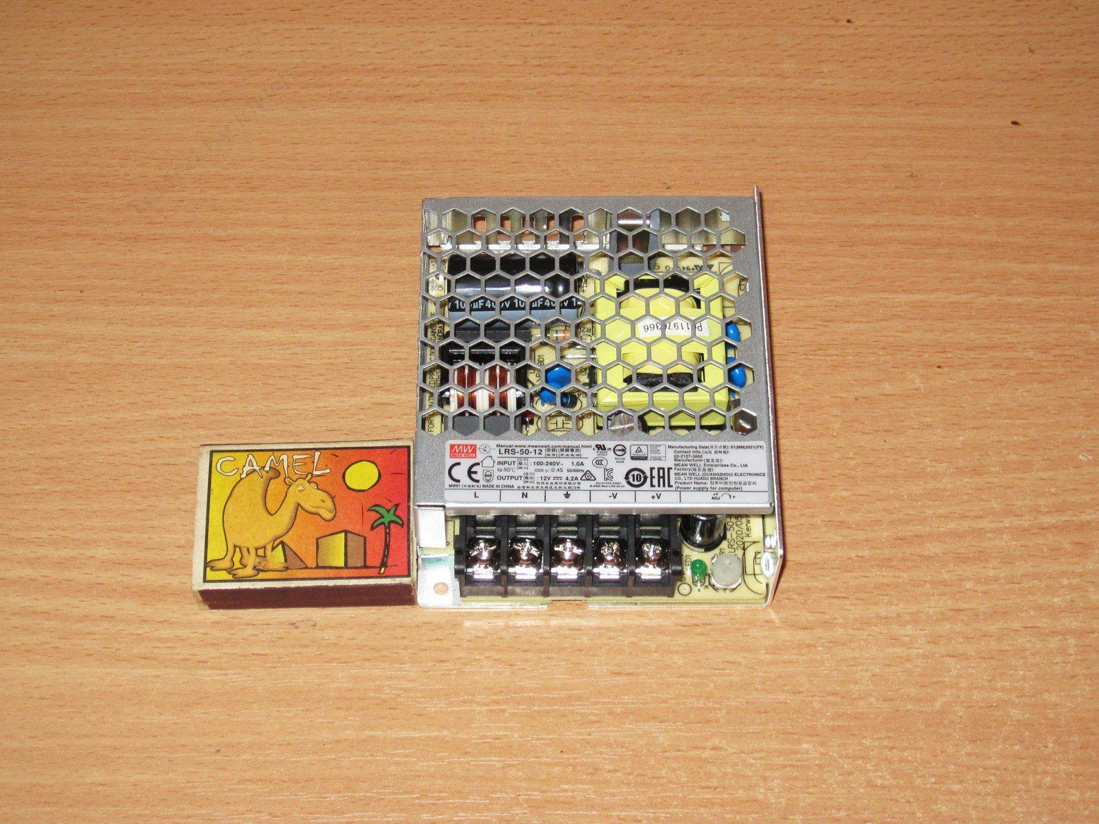
The case consists of an aluminum chassis with a perforated cover. The perforations are fairly large, especially given how small the case is.
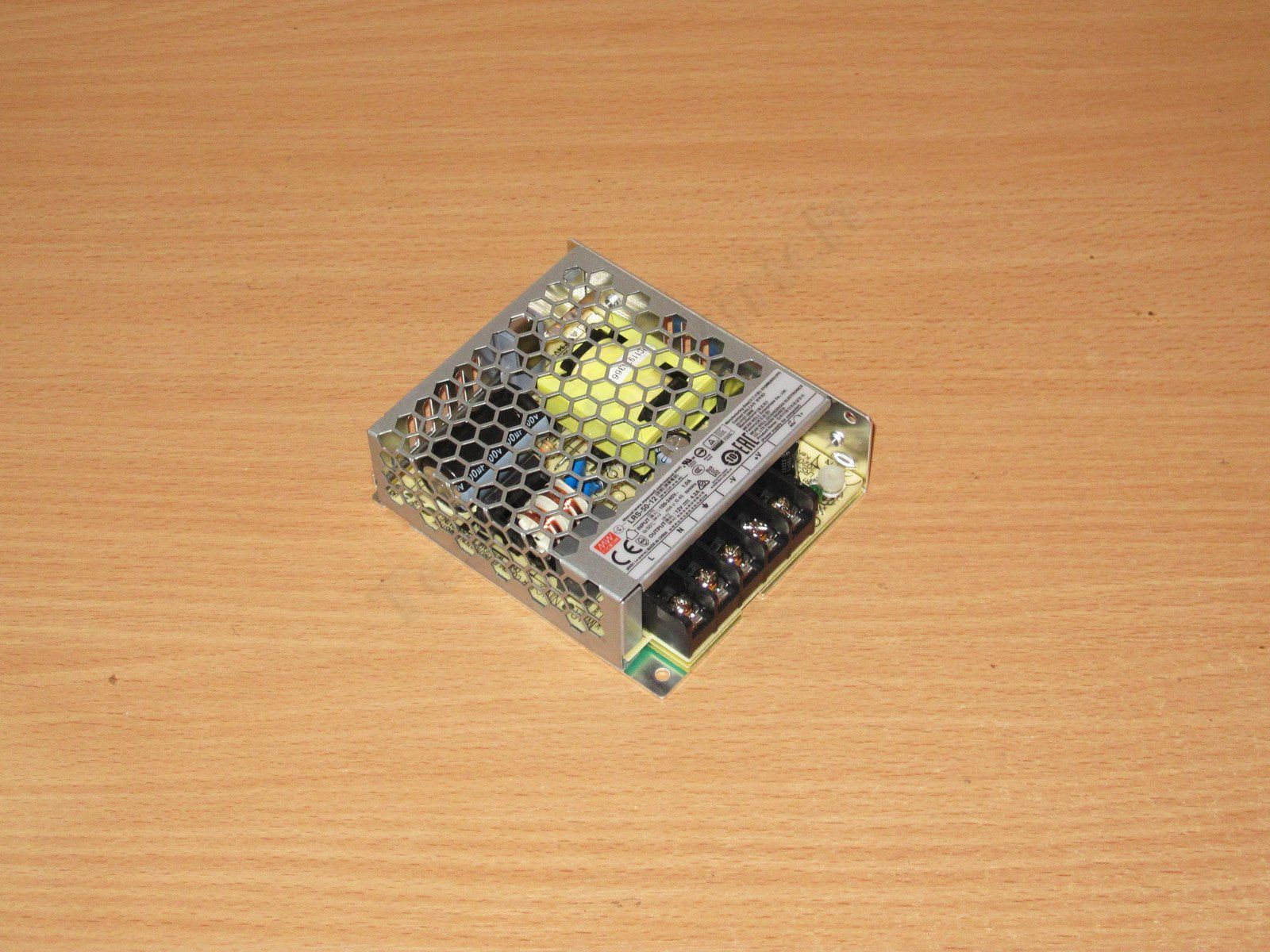
The range includes seven models: 3.3, 5, 12, 15, 24, 36, and 48 V. The 5, 12, and 24 V models are generally the most common, with 48 V models a little less so. Unfortunately, the others are harder to find.
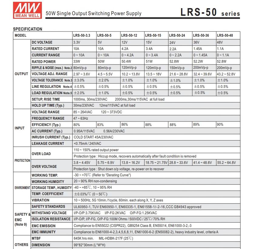
A standard terminal block is fitted at one end, with the power indicator and trimmer on the right. The LED is very dim; they could have made it brighter.
The terminal block also looks a little oversized for such a small case.

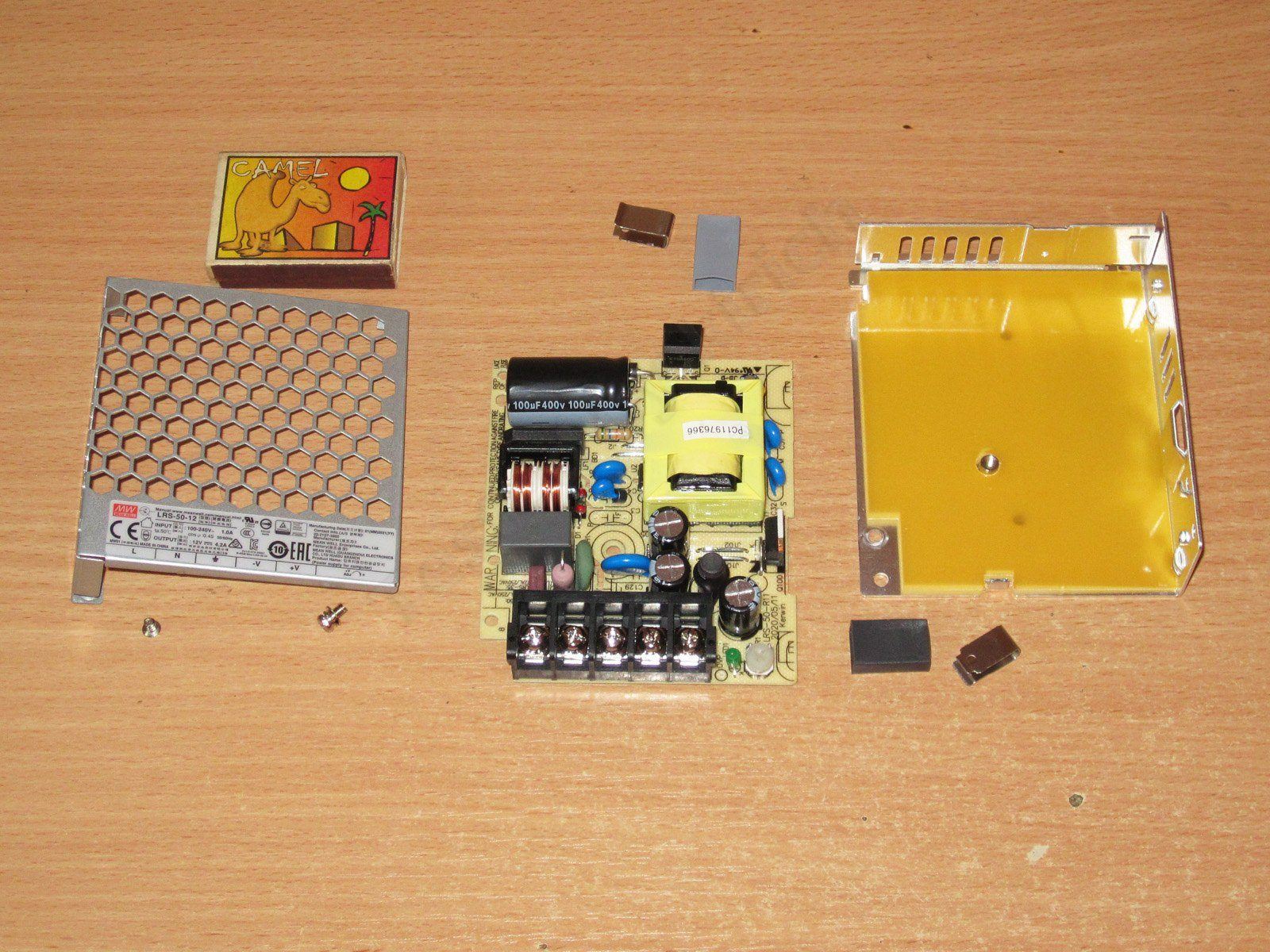
Speaking of size, here's a comparison with a standard matchbox.
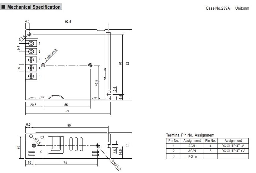
And here are the approximate dimensions from the datasheet :)
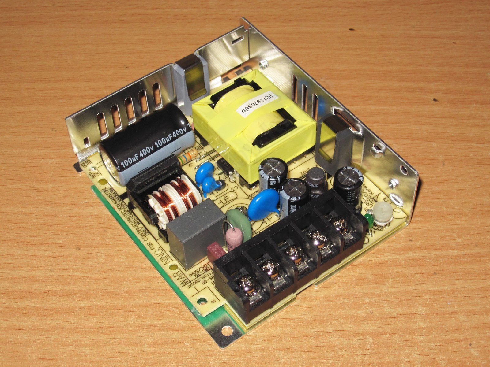
It comes apart in the usual way: remove the self-tapping screw and slide off the cover.

Everything inside is neatly laid out. The only thing is, the transformer looked a bit too large for 50 W; in some cheap “Chinese” power supply, they'd claim at least 100 W.
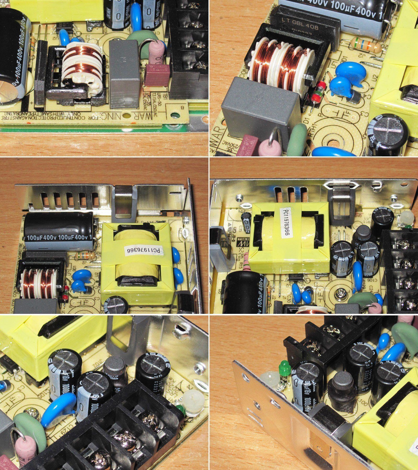
1. The input has an almost complete filter; the only thing missing is a varistor.
2. There's even a spark gap in the input choke circuit.
3. The 100 µF input capacitor has plenty of headroom for our mains voltage and is adequate for the full input range. The transistor is held down by a spring clip rather than screwed in, as is more often the case.
4. The output diode assembly is secured in the same way.
5, 6. The output has a choke to reduce ripple and 1000 µF, 16 V capacitors. This last detail gave me some pause: in my opinion, 16 V is cutting it very close; 25 V would have been better. It also gets in the way of my modification a bit.
I remove the clips, undo the screw, and take out the board for a closer look.
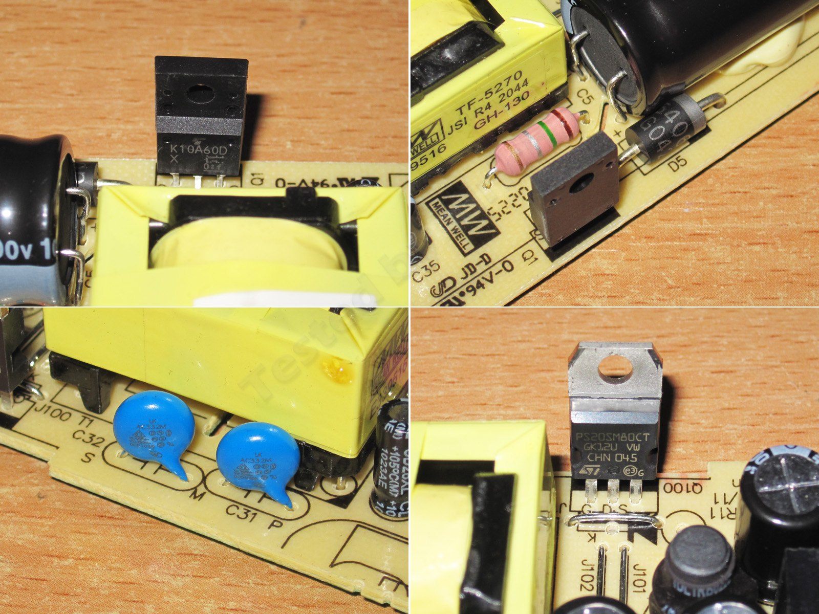
1. K10A60D high-voltage transistor
2. The snubber uses a TVS diode rather than the usual RCD circuit; the current-sense resistor is next to it.
3. There are two Y capacitors connected in series, which is quite useful and improves reliability and safety..
4. PS20SM80CT output diode assembly, no issues there.
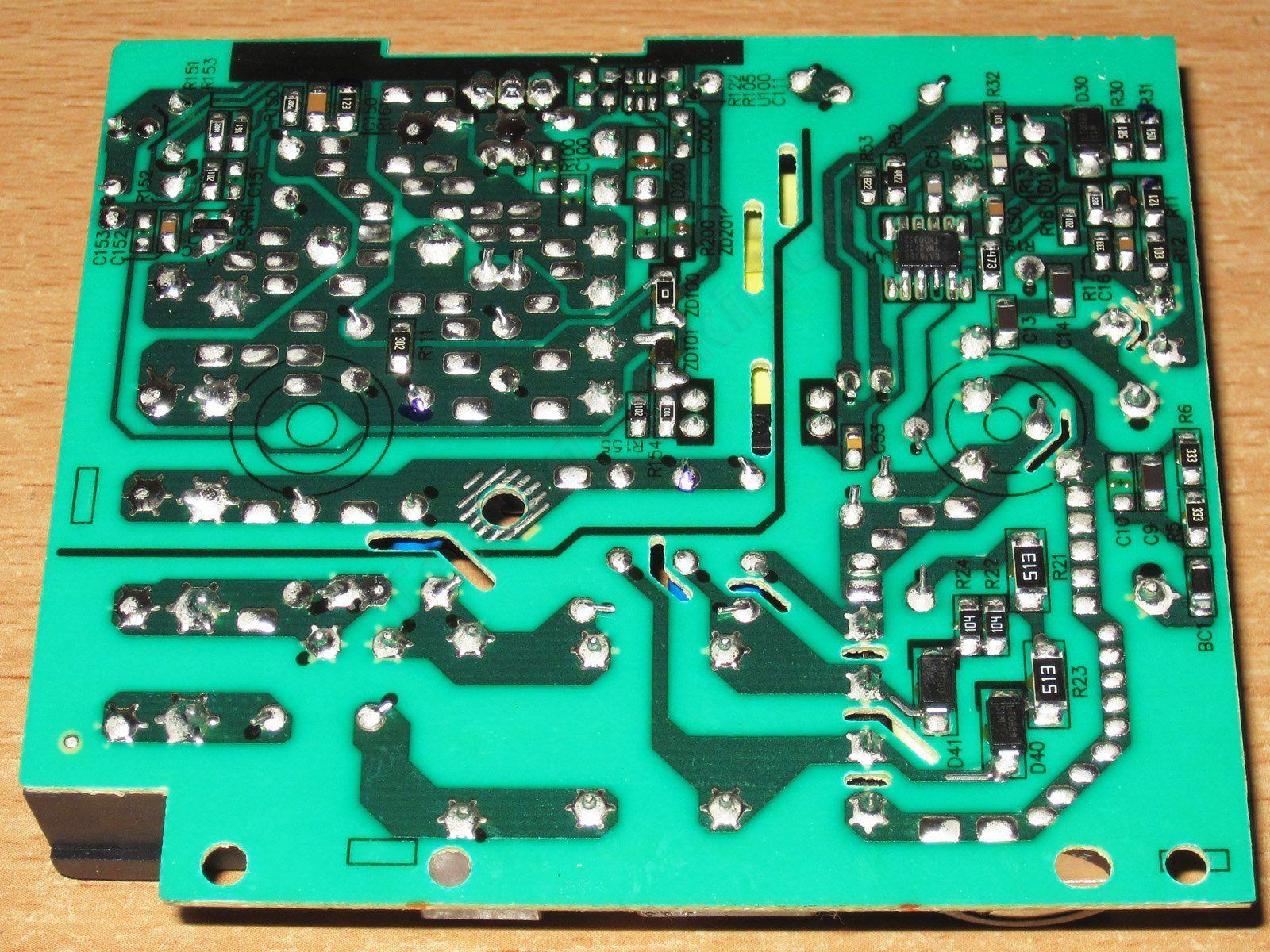
The board has safety slots, and the clearance between the hot and cold sides is sufficient.
1. TEA18363T PWM controller from NXP
2. The PWM controller's startup circuit is interesting: it runs from the input mains through two diodes. What's even more interesting is that there are three 51 kΩ resistors in series, but one of them is made up of two 100 kΩ resistors.
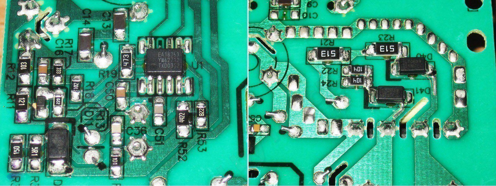
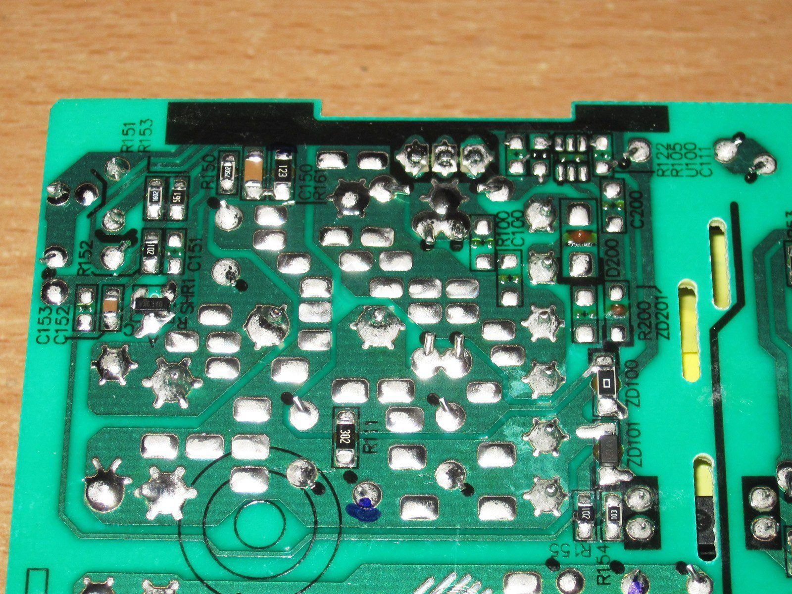
The board has a footprint for a synchronous rectification controller IC, and the MOSFET pinout is marked near the diode assembly terminals. This feature isn't used in this power supply, though; it's for the 3.3 V and (presumably) 5 V models.
I power it up and check it. The output is about 12 V, and the wattmeter doesn't register any power consumption. The adjustment range is 10.5–14.18 V. The adjustment is fairly coarse.

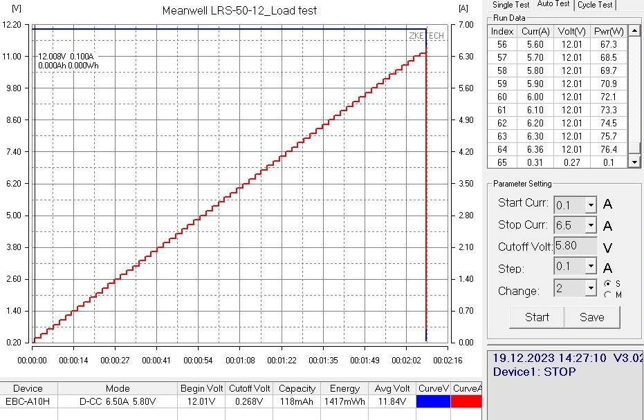
When I checked the protection trip threshold, I found that the power supply shuts down at an output current of about 6.4–6.5 A, which is about 1.5 times the rated 4.2 A.
I need plenty of headroom for my application, since the power supply runs fans, which can sometimes have a high inrush current depending on the fan model and the type of its controller.
I should mention the excellent output voltage regulation: it stayed rock steady across the entire load range.
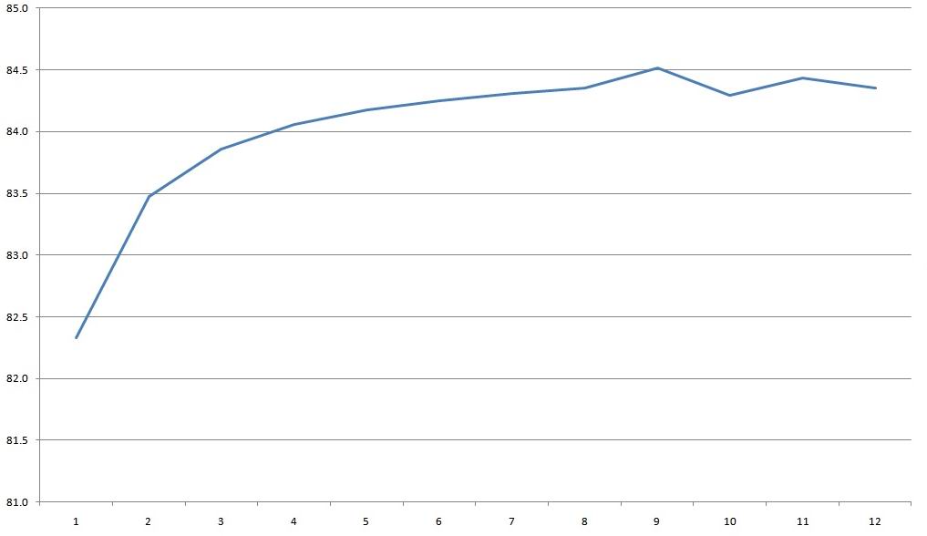
The stated efficiency is 86%. I measured closer to 85%, but my wattmeter has a relatively high margin of error, especially at low power levels.
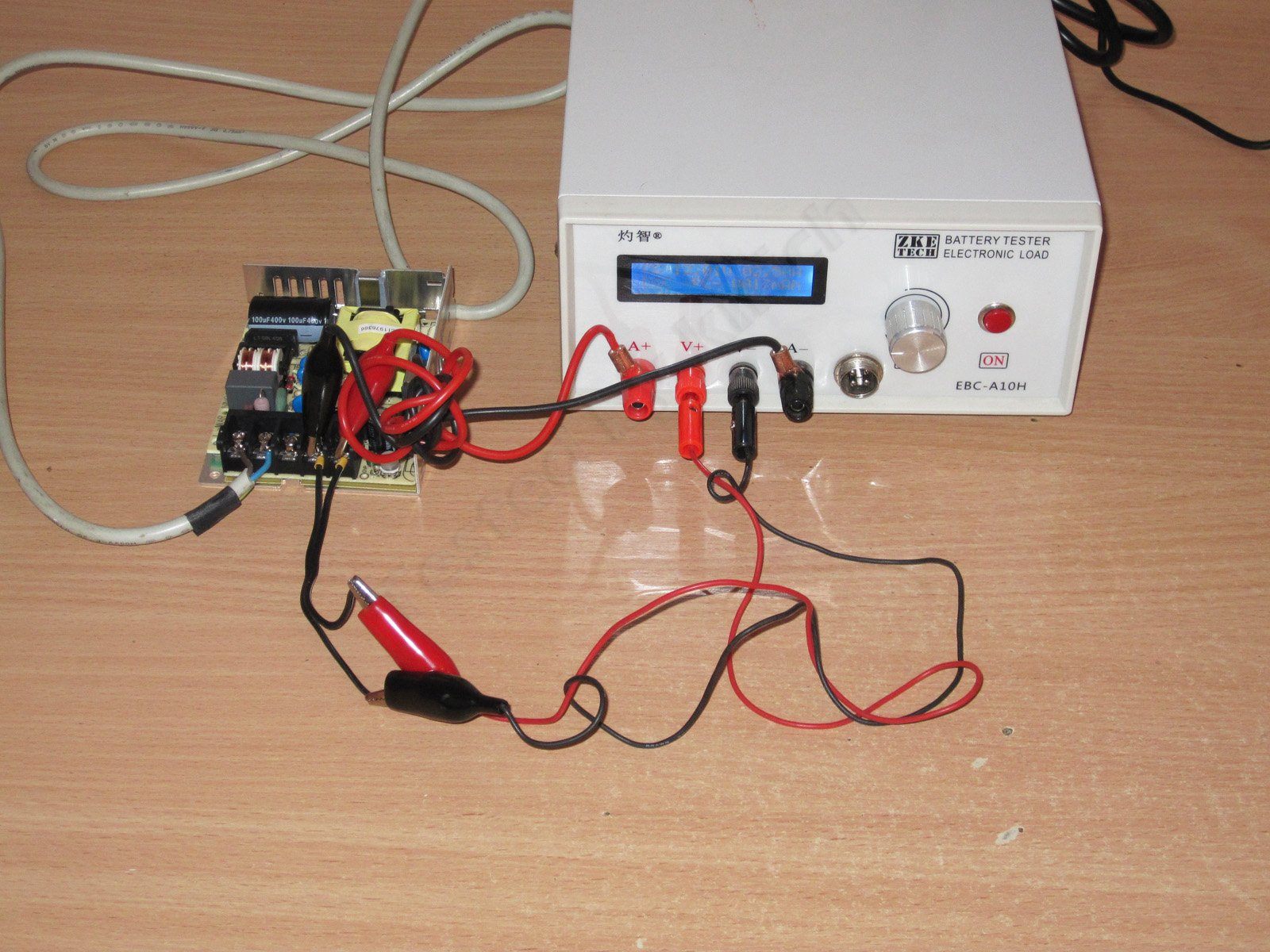
I used the EBC-A10H load for most of the tests. However, since I had it tied up testing batteries, I had to run the thermal tests with the EBC-A20. The connection was, of course, four-wire.
For ambient temperatures from -25 to +50 degrees and on the mains, continuous operation at 100% load is allowed. It can also operate at -30, which can sometimes be useful.
I should also note that the controller uses a different operating frequency for different mains conditions.

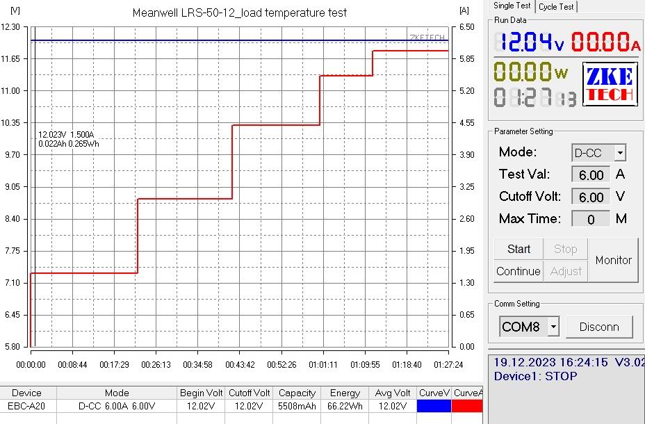
I started the test in 20-minute stages at load currents of 1.5, 3, and 4.5 A—that is, slightly above the full-load current of 4.2 A. Then I ran it for 10 minutes at 5.5 A and another 15 minutes at 6 A. So the test was effectively conducted at almost one and a half times the maximum power, but the power supply was just sitting on the table and the ambient temperature was about 21 degrees.
The voltage remained stable throughout the test, but rose slightly after the load was removed—by just 20 mV—which is a very good result.
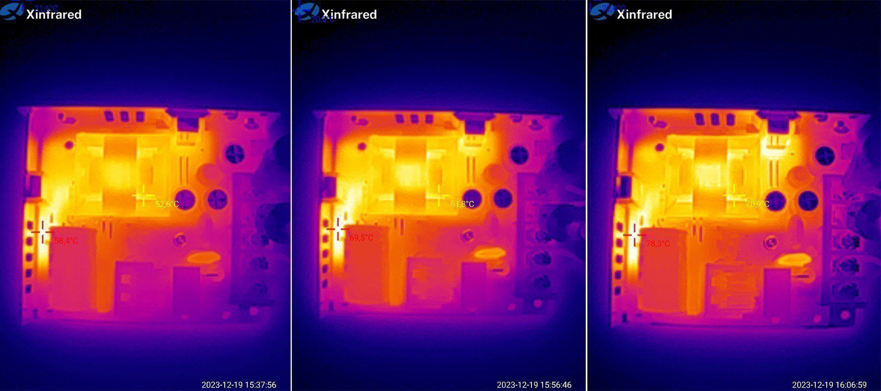
Here are the results at load currents of 3, 4.5, and 5.5 A. I think they’re pretty good. At 5.5 A output current, the hottest component was the snubber TVS diode at 78 degrees, while the transformer was around 71 degrees. At an ambient temperature of 50 degrees, these readings would rise by 30 degrees, respectively, but would still remain within a safe range.
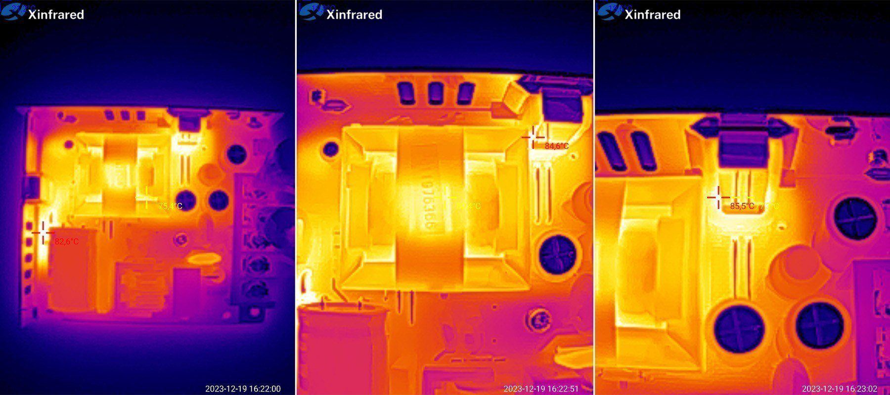
But the results at 6 A are more interesting. The TVS diode reached 82.6 degrees, the transformer was just over 80 degrees, and the area around the output rectifier assembly was at 85.5 degrees. I’m repeating the readings in text because they’re hard to see in the photo.
I think these results look very good, especially considering the nearly 1.5× overload.
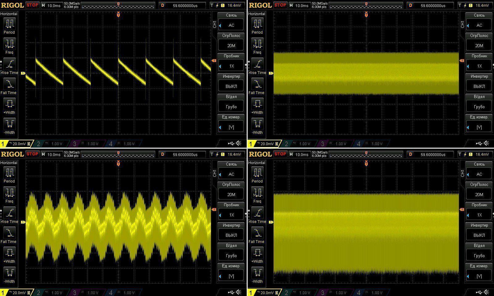
All right, that’s great, but what about ripple? The manufacturer specifies 120 mV p-p.
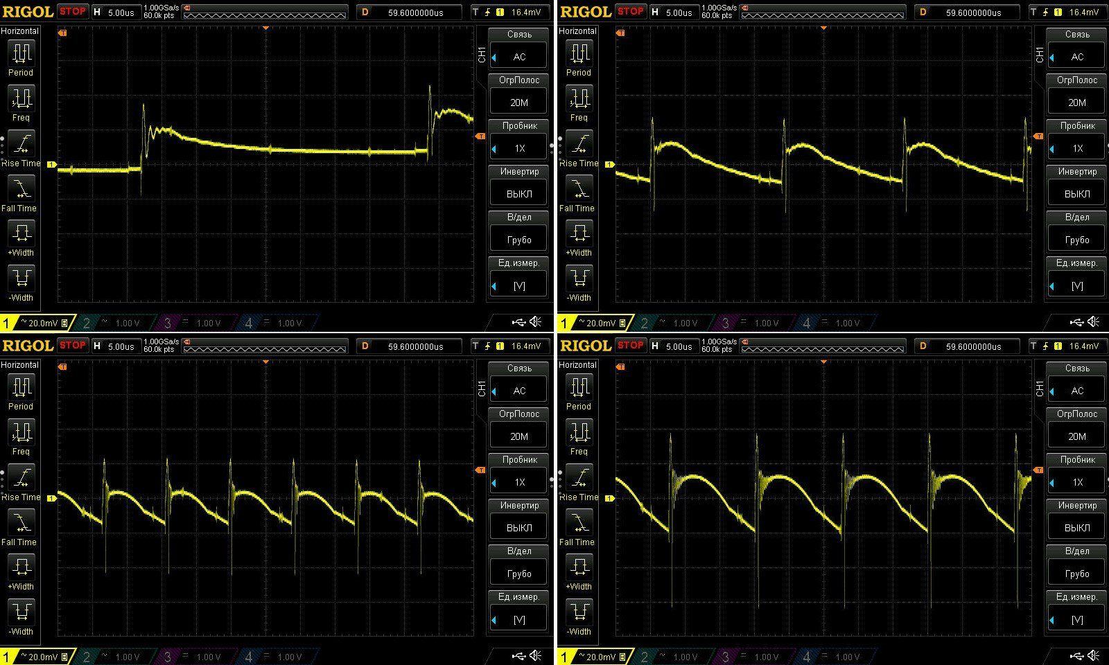
First, the high-frequency results. For the no-load measurement, I had to increase the timebase because the power supply has a “green” mode and greatly reduces its switching frequency.
Measurements were taken at the output terminal block; no C+C filter was used.
1. No load
2. 2 A
3. 4 A
4. 6 A.
At 4 A, I measured around 70 mV; at 6 A, it was about 100 mV. In any case, the results did not exceed the specified 120 mV.
There was something odd with the low-frequency ripple. At 2 A, everything looked good and predictable. At 4 A, 100 Hz ripple appeared, but when I increased the load to 6 A, things went back to normal. Strange—maybe I’m missing something? I only changed the load current; I didn’t do anything else.
Interestingly, with no load, the startup pulse has three levels. I hadn’t noticed that before.

Just a couple of words about the modification. I need around 14.5–15 V at the output, preferably 15 V, so I was planning to do this from the start.
But there’s a catch: as I mentioned above, the capacitors are rated for 16 V, which isn’t ideal for a 15 V output. Given the specifics of my particular application, it’s not critical, but if you do this modification, it’s still better to replace them with 25 V capacitors.
Replacing the capacitors is no problem, even for a beginner, so I’ll just show what to do to change the voltage (for example, if you need 15 V but only have the 12 V version). Of course, this applies only to this particular model.
There’s a feedback circuit and a resistor divider on the board. You just need to add a resistor of around 100 kΩ. I had an 82 kΩ resistor on hand, and that works too. Solder it in roughly the intended spot; a 1206 or 0805 resistor fits there perfectly.
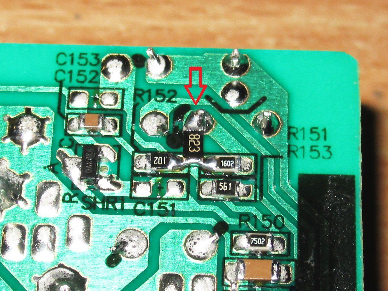
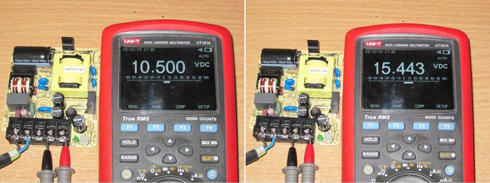
This gives you an adjustment range from the same 10.5 V as before up to 15.4 V. With a 100 kΩ resistor, the maximum voltage will be slightly lower.
Conclusion.
What is there to say? This is a typical example of a high-quality branded power supply. The only thing I personally didn’t like was the 16 V output capacitors instead of 25 V ones. A few other things seemed a little odd too: 100 Hz ripple at a load current of around 4 A. I wouldn't call it critical, since the ripple amplitude is small, but it is a bit strange.
Oh, right, I almost forgot: the LED glows dimly, but those are definitely all the drawbacks :)
That's all for now. I hope this was useful. Thanks for reading, and of course, thanks for your comments.
660₴
This page was found when searching for:
электрическая схема блока питания lrs-50-r11, mw lrs 50-24 схема, схема блока питания lrs 50 r7 kerwin, frs-50-12 блок питания для контроллера питания заточных станков, схема блока питания lrs 50-12, без трансформаторный блок питания на 12 вольт 50 вт, lrs--50-12 какой пусковой ток выдержит через нагрузку, источник питания lrs-50-5 регулировка выходного напряжения, 4, 1, lrs-50 mean well j,pjh
электрическая схема блока питания lrs-50-r11, mw lrs 50-24 схема, схема блока питания lrs 50 r7 kerwin, frs-50-12 блок питания для контроллера питания заточных станков, схема блока питания lrs 50-12, без трансформаторный блок питания на 12 вольт 50 вт, lrs--50-12 какой пусковой ток выдержит через нагрузку, источник питания lrs-50-5 регулировка выходного напряжения, 4, 1, lrs-50 mean well j,pjh
The figures from this review are in the measurement database: Power supplies
Calculate manuallyAll calculators
Discounted products
You may be interested in



Discounted products
Support the project
All the content on the site and the advice are free, but we’d be grateful for your support of the project and the channel!
Comments1
Discuss on the forumHave a question or some experience to share? Discuss the article with the author and readers: the forum is a convenient place to share schematics and photos.
Go to the forumOnly registered readers can comment. It takes a minute to sign up, and you can log in with the same account you use on the forum.
Log inRegister
Comments are published in their original language.