
A couple more 12 V power supplies, this time rated at 500 and 600 W
These are the latest power supplies in this form factor to come my way for testing, but I doubt they’ll be the last in the long run.
They left me with mixed feelings: not bad, but with a few “caveats.” As always, more in the review.
A reminder: to keep up with new posts on the blog, I recommend following me on Instagram. I’ll post notifications about new articles there and might also share something interesting - link to my account
You can also subscribe to updates and new articles on the Telegram channel - https://t.me/KirichBlog
I probably won’t have anything radically new to say today. Like most Chinese products, these have their shortcomings, but the process of tracking down and prodding various factories to make changes to their products continues, so I think some reviews will get a follow-up.
I have to say, though, that surprisingly, Chinese manufacturers are willing to listen and try to improve their power supplies based on some of my recommendations, which is encouraging. Unfortunately, in my dealings with another manufacturer—the one that makes electronic loads—they’ve shown an impressive degree of stupidity. But never mind, I’m not giving up :)
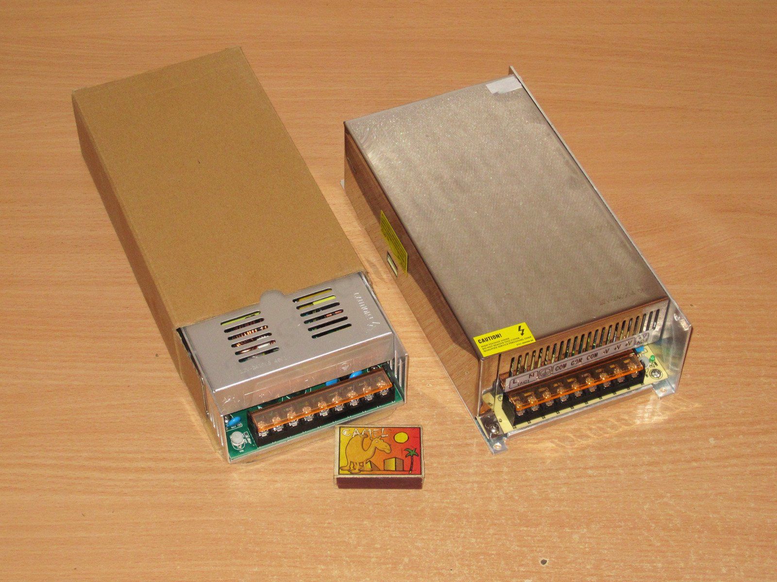
So, here are two power supplies in front of me: one in a box, the other looking pretty :)

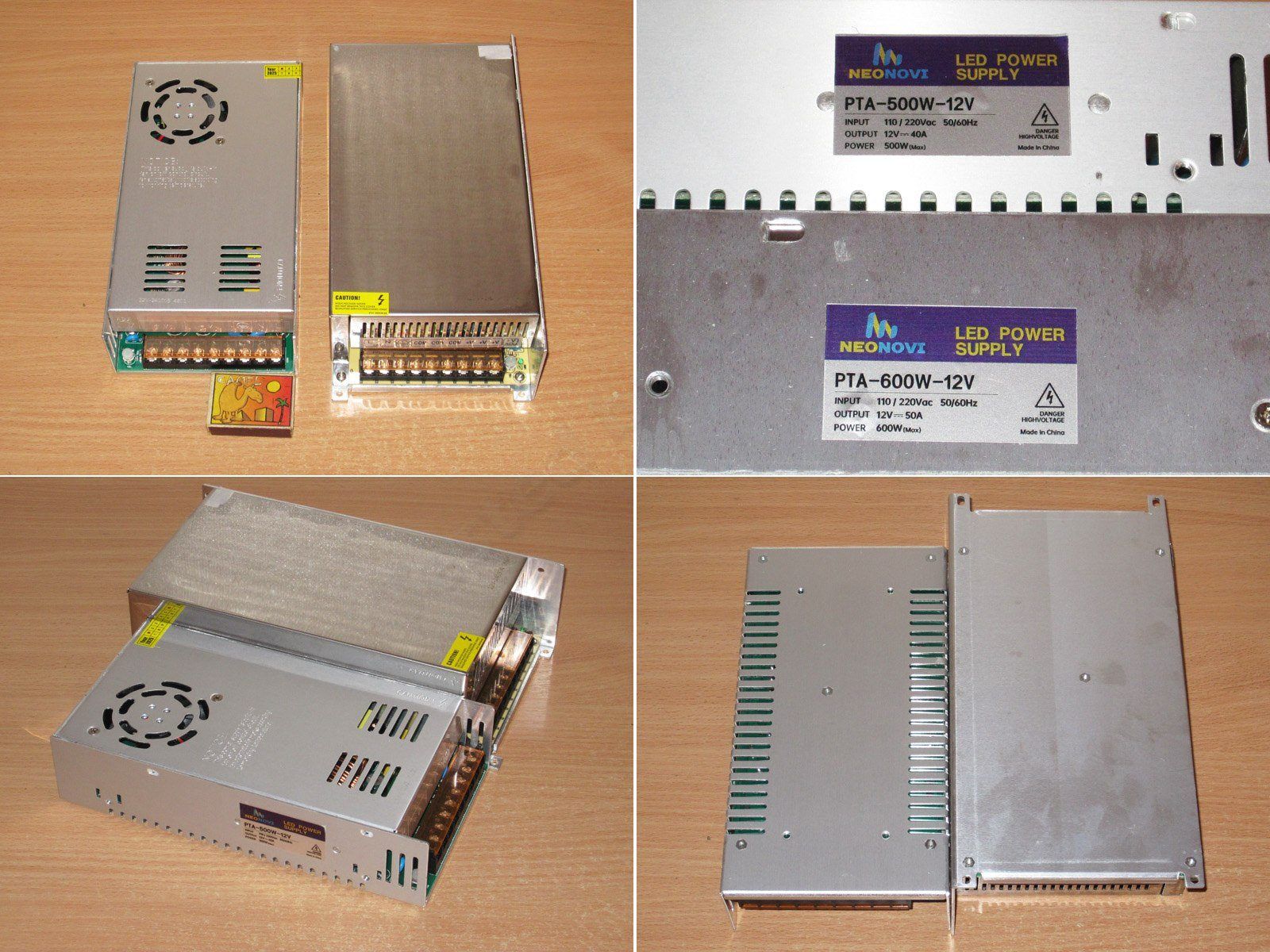
The power supplies themselves aren’t anything special: one is rated at 500 W, the other at 600 W. There is one small oddity, though: the 500 W model is rated for 40 A, which works out to 480 W, not 500. But that’s a minor detail. The product page actually lists the power correctly as 480 W.
The 500 W model measures 215x115x50mm. The 600 W model is noticeably larger, especially in thickness: 240x124x66mm.

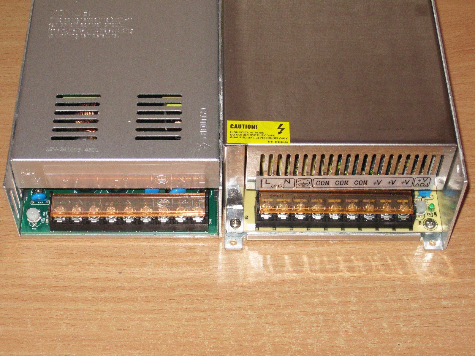
The output voltage is adjustable, and there’s a terminal block with a cover. The output is split across three terminals for each polarity, and I recommend using all the terminals when running at maximum load.

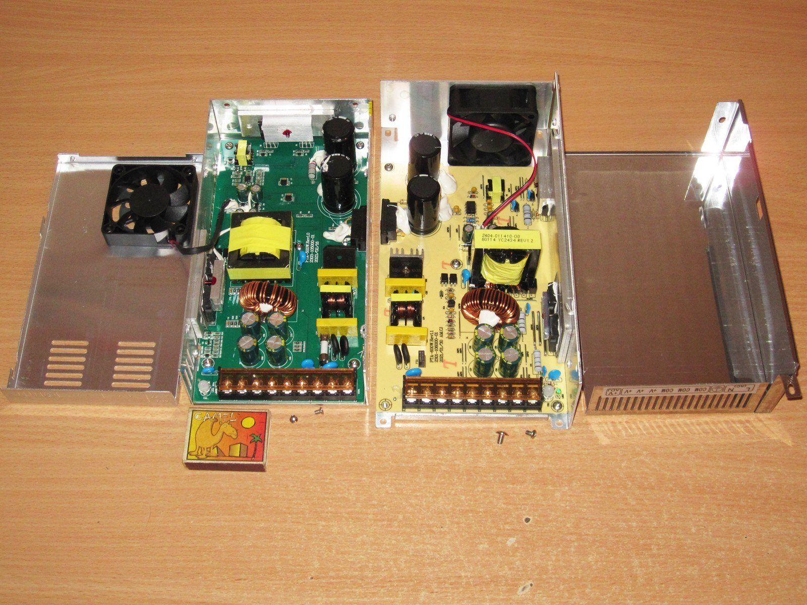
I’d like to say the insides of these power supplies are very similar, but they aren’t. Despite the relatively small difference in power, they’re quite different inside—in the PCB material and color, as well as the layout. The only thing they really have in common is the topology.

I’ll start with the lower-powered model, PTA-600W-12V - link.
This model looks very much like the most common power supply in this type of enclosure. I wouldn’t be surprised if there were millions of them. The green PCB is a little unusual, as is the fact that it seems to be fiberglass rather than phenolic paper. I’ve rarely seen green boards in power supplies like this; usually they’re either very low-power units or, conversely, very powerful ones.

The PCB is double-sided, which is also fairly uncommon in power supplies like this. A board like that is usually more expensive, too.

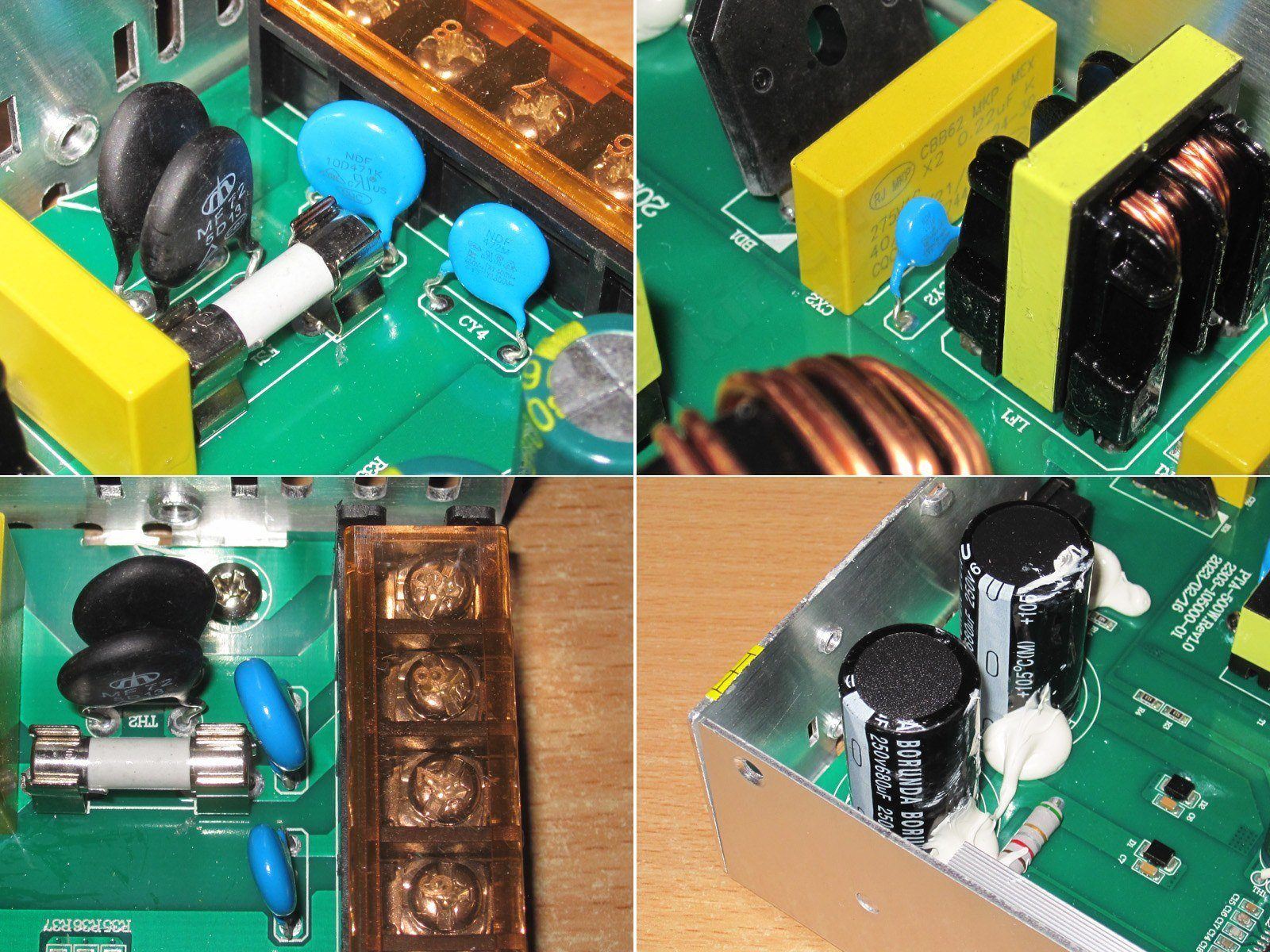
Interestingly, it has a proper input filter, including not just an inductor and a thermistor, but also a pair of X capacitors and even a varistor.

1. A varistor rated for 470 V peak, a standard value.
2. There are also small Y capacitors tucked between the inductor and the X capacitor.
3. This is a serious design flaw. The designers deserve a smack on the knuckles for this one. Remember: the varistor must always be placed after the fuse!!!! Here, you can clearly see that the varistor is effectively connected straight across the input.
4. The input capacitors are from the same mysterious manufacturer as those in the power supplies from another review. Their stated capacitance is 680µF.

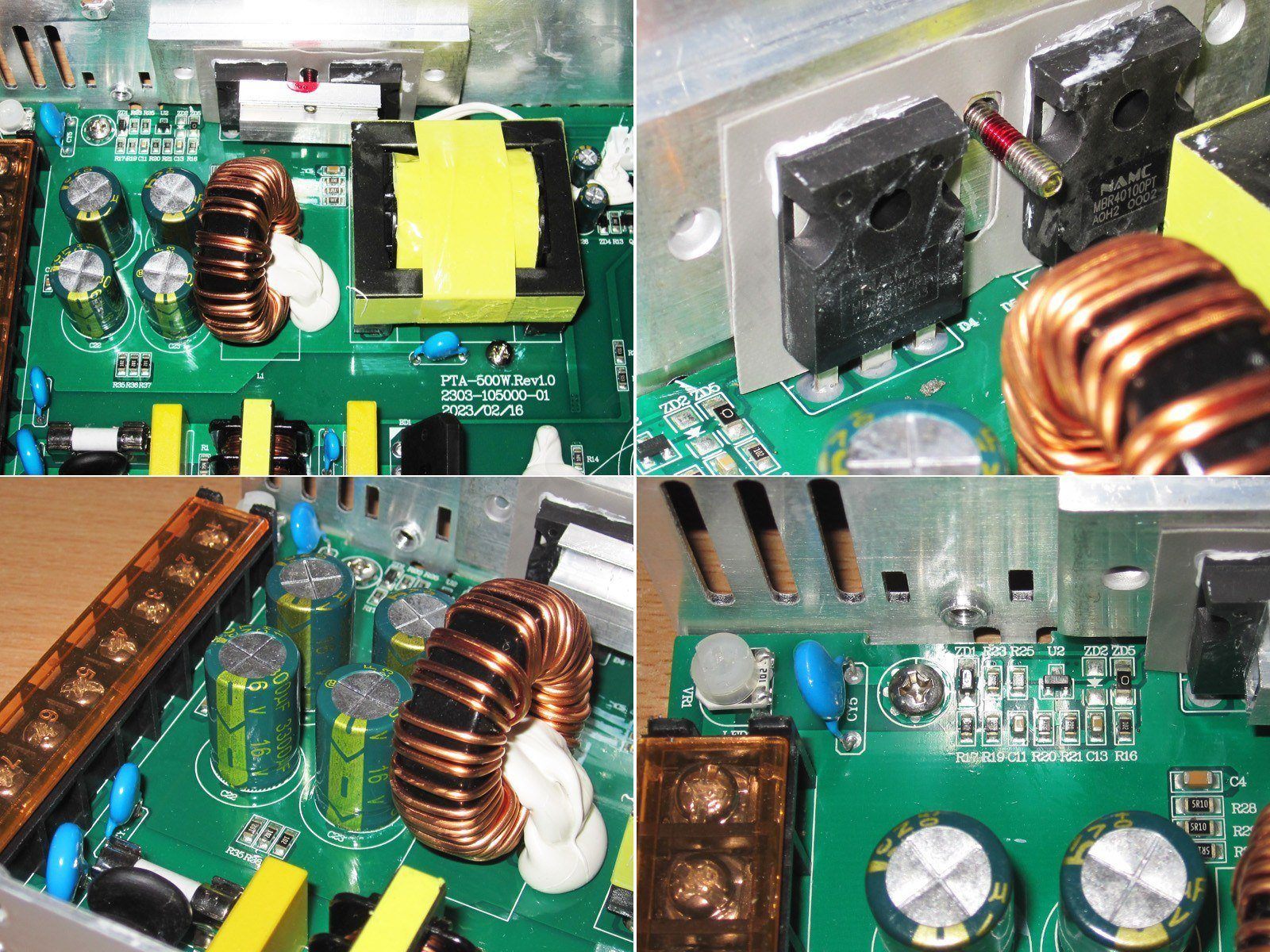
Interestingly, there’s a lot of unused space—literally a section of the PCB with no components on it.

1. The power supply section for the PWM controller and... the fan. At least, I couldn’t see a temperature sensor.
2. The PWM controller itself, a KA3845.
3. PTA18N45 transistors, rated for 18 A and 450 V.
4. Two optocouplers are tucked away near the transformer, which usually indicates an output overvoltage protection circuit.
The power supply uses a half-bridge topology. Nothing new here.

1. The output section has a completely conventional layout: a pair of diode assemblies, an inductor, and several capacitors.
2. The diode assemblies are different: 50 A on the left, 40 A on the right. The voltage rating is the same, 100 V.
3. There are four 3300µF capacitors. In my view, that’s a generous margin for this topology and output current.
4. Feedback and overvoltage protection circuit.

The board is single-sided, so the underside is empty and there are no electrical safety concerns—except for the incorrectly installed varistor, which I mentioned earlier.

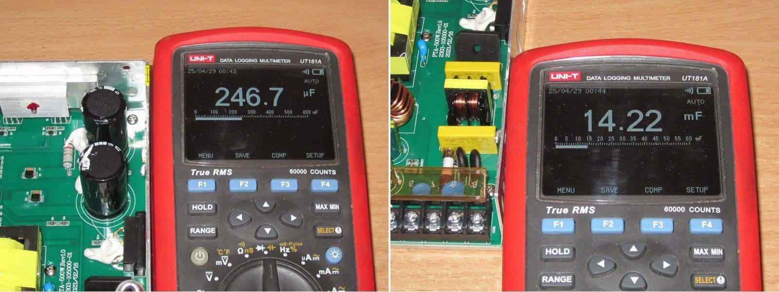
The input filter capacitance is 247 µF, which means the capacitors are about 500 µF each—clearly less than the stated 680. In fact, even 340 µF (two 680 µF capacitors in series) is a bit low for 500 W, and here they've gone even lower.
The output side is fine, with about 14,000 µF in total.

The output voltage adjustment range isn't very wide, roughly 11.2 to 12.8 V, and I wouldn't say the adjustment itself is smooth, though that's not a big deal.

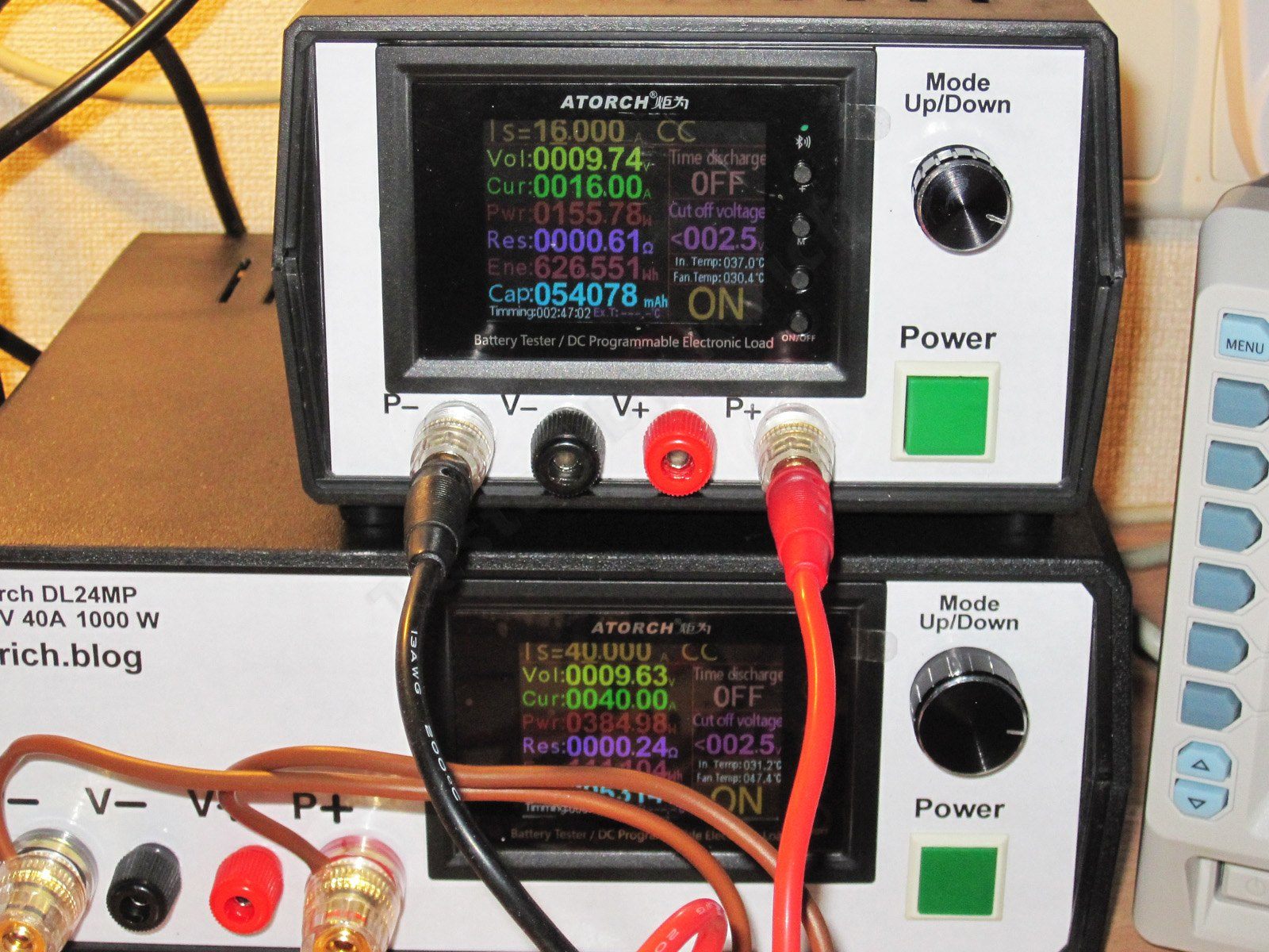
For the tests, I used a pair of electronic loads, an oscilloscope, a multimeter, a wattmeter, and a thermal camera. One load would have been more than enough in terms of power, but its 40 A limit is a significant restriction, so I had to use two.

The protection is set rather crudely, and the controller starts reducing the voltage at around 54–55 A, which is clearly too high for a 40 A power supply.

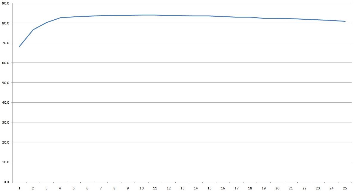
Efficiency was measured from 2 to 50 A in 2 A increments and peaked at about 84%. That's not very high, but it's pretty typical for a Chinese power supply.

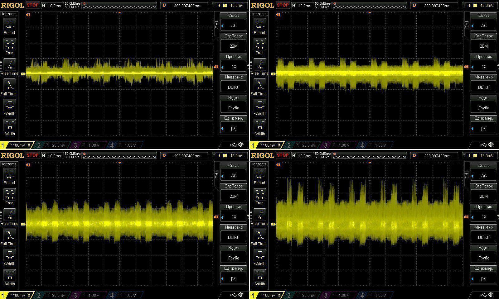
I have no complaints about the high-frequency ripple at all: less than 150 mV at 40 A is very good. Here are the results with no load and at 13, 26, and 40 A.

The low-frequency component is also fine. Yes, there's some ripple at 100 Hz, and the filter capacitance is low, but the amplitude is still well within acceptable limits.

Next up was supposed to be a load test, but it didn't quite go as planned.
1. Exactly 12 V with no load.
2. At 13 A, it was 11.984 V when cold—fine.
3. After warming up at 13 A, it was 11.985 V—perfect.
4. At 26 A, it dropped to 11.969 V—fine.
5. After warming up at 26 A, it was 11.966 V—perfect.
6. I raised the current to the maximum of 40 A; it dropped to 11.947 V—excellent.

But I set it to 40 A, went out for a smoke, and heard the load slowing down its fans. Something was clearly wrong.
When I came back, I saw that the power supply had shut down. I tried again, and it shut down again. I lowered the current to 39 A, then 35 A, then 32 A, and only at 30 A could the power supply run continuously.

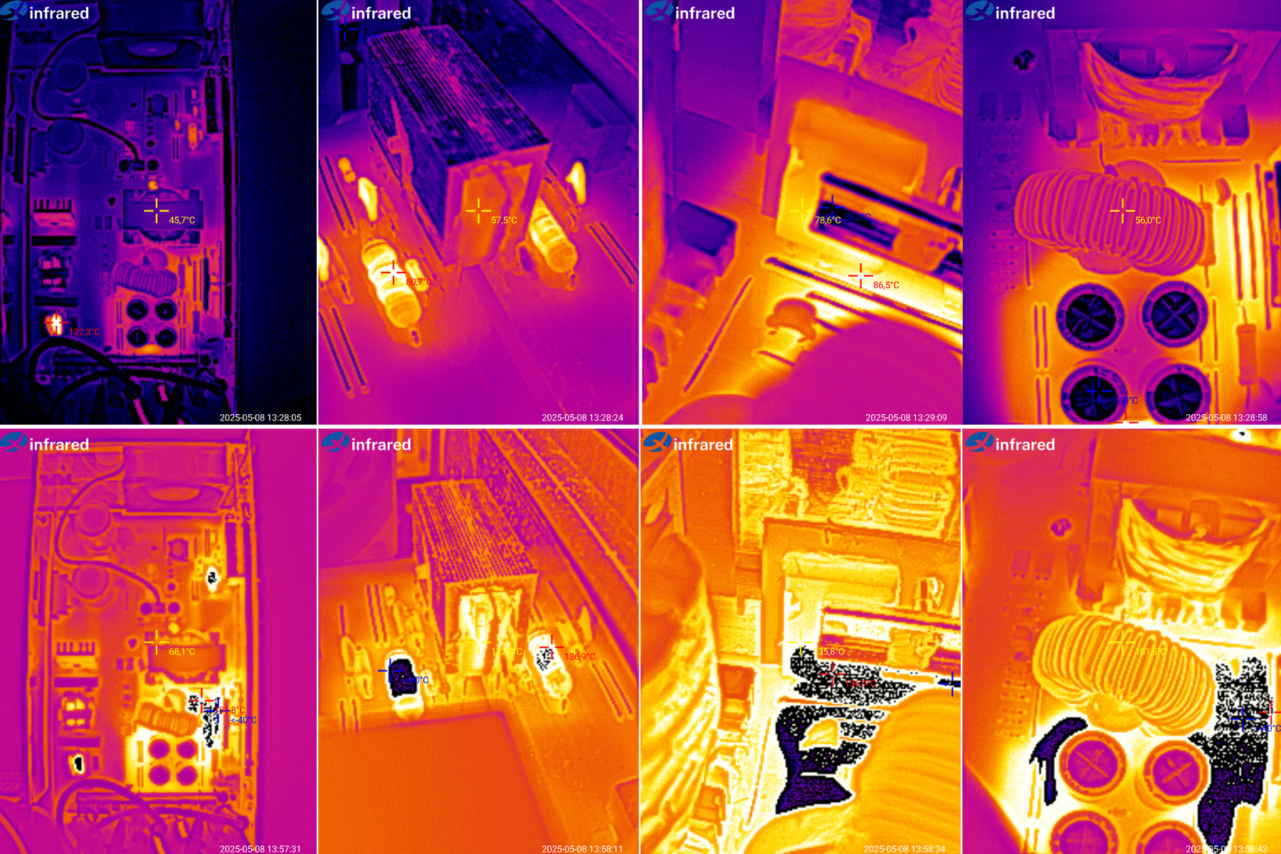
Temperatures at 13 and 26 A. Nothing alarming, really, except that one of the diode assemblies is running hotter than expected.

At 30 A, everything was also fine except for the temperature of that same diode assembly. 105 °C is a bit much, though not critical.
On the other hand, 30 A is a long way from the maximum of 40 A.

I took a closer look at how the power components were mounted and found a gap between the heat spreader plate and the case. Actually, not just a gap—a GAP. It's there for both the diodes and the transistors, although the transistors weren't overheating.

I removed the plates and, while I was at it, took the power supply apart out of curiosity. I also checked the thermal protection: there's an 85 °C thermal switch that cuts power to the PWM controller. The thermal switch itself is installed inside the diode clamp bar.
I held it in place and realized that the case was slightly bent around the mounting points. I tried to straighten it, then applied thermal paste between the plate and the case around the diodes and transistors and put everything back together, but I can't say anything looked visibly different.

I started with a half-hour test at 26 A—fine. Then I raised it to 32 A, also without any issues. But as soon as I increased the current to 35 A, it shut down due to overheating again.
I stopped experimenting there, since I don't see any point in investigating the cause. I'll pass the information on to the factory.
And now I'm of two minds about it. On the one hand, it has thermal protection, which is great: you simply can't burn the power supply out. On the other hand, because of the cooling issues, it can only deliver 75% of its rated power continuously. It can still supply 40 or even 50 A, but only until the protection kicks in.
I should also mention that the fan is fairly quiet. It appears to be rated for 12 V, 0.16 A.

The second power supply, PTA-600W-12V, link
The layout, board material, and color are all different. And unlike the previous model, which used SMD components, this one uses only through-hole components.

The inside looks extremely simple—almost as if they forgot to install some components :) Judging by its appearance, it uses the same topology as the previous model: an asymmetric half-bridge.

To be fair, when I saw the large polished metal case, I expected to find something inside like what I saw in the 800-watt power supply. At least they look identical on the outside, but the insides are completely different—in other words, these are power supplies in entirely different classes.

The input filter is the same as in the previous model, including the varistor before the fuse. The only change is that a heatsink has been added to the bridge rectifier.

As in the previous model, an output overvoltage protection circuit has been added alongside the main feedback loop.

The PWM controller is a UC3845, essentially the same as the KA3845 in the previous model.
The transistors are more powerful here: 20N50, rated at 20 A and 500 V, versus 18 A and 450 V in the previous model.
The output has the same inductor and a pair of diode assemblies, but here they're both rated for 60 A, rather than 60 A and 40 A.
Another difference is that the previous power supply had two small heat spreader plates, while this one has a single large one covering almost the entire side of the unit.

The transformers look similar in size, but they're actually different. The 500-watt version measures 45x41x13.5, while the 600-watt version measures 43x43x15 mm.

The PCB clearances are adequate, so I have no concerns about the safety of the layout.
The circuit design does have a few changes, though. The previous model had voltage regulators in the fan and PWM controller supply circuits; this one doesn't. Interestingly, that makes the fan quieter. It runs quietly up to a load current of about 4–5 A. Increase the load current, and it reaches full speed at around 7–8 A.

The input capacitors are another disappointment: their actual capacitance is about 500 µF instead of the stated 680 µF. As you can imagine, that's an even bigger problem here, since this power supply is more powerful.
The output capacitors are fine—in my opinion, they even have some headroom.

The output voltage adjustment range is slightly narrower than on the 500-watt version: 11.45–12.7 V.

I used two electronic loads for the tests as well. The lower one was the main load; the upper one was added when 40 A wasn't enough. The upper load alone would have been sufficient for a 600-watt unit, but unfortunately it only goes up to 40 A.

I tried to determine the protection trip point, but this protection doesn't have a fixed threshold; it just reduces the output voltage.
At 58 A, everything is stable. Around 11 V is fine: that's the voltage drop across the power supply itself plus the drop in the wires. At 60 A, the voltage starts to sag; at 62 A, the drop is clearly noticeable. Next, I gradually increased the load current to 64 and 66 A, but the power supply didn't shut down. I didn't risk increasing the load current any further; I wanted to run some more tests :)

I measured efficiency from 2 to 62 A in 2 A increments. The results were about the same as for the previous unit. At 60 and 62 A, the voltage dropped slightly, but that's an overload condition, so it's normal.

Ripple was measured with no load and at currents of 17, 34, and 51 A. I connected the probe directly to the terminals, just as I did when measuring the previous power supply.
The high-frequency ripple is somewhat worse here. The previous unit had up to 150 mV, probably closer to 130 mV, while this one reaches about 250 mV at maximum load. That's perfectly normal given its power, though the difference is a little surprising.

The low-frequency ripple is much worse, though: the 100 Hz ripple is quite pronounced. That's even stranger, since the two power supplies use the same circuit design, the same capacitor values, and almost identical transformers. Maybe something went wrong with the PWM controller's surrounding components or the PCB layout.

I had to improvise to check the thermal performance, since removing the cover while the unit was running wasn't very convenient. In the end, I made a makeshift cover to simulate the original one.

First, though, here's how the output voltage changes with load current and temperature.
1. No-load voltage with the power supply cold
2. 17 A load
3. 34 A load with the power supply warm; the voltage has dropped by about 0.3 V
4. 51 A load with the unit warmed up; the voltage has dropped by about 0.55 V
5. 51 A load with the power supply hot; the voltage is now 0.65 V below its initial value, which is quite a difference.
6. No-load voltage with the unit warmed up; the difference is about 40 mV.
As you can see, the voltage barely depends on temperature, which is very good. But it depends heavily on the load current. I think the feedback pickup point was chosen incorrectly. In practice, the unit's output voltage drops by about 5%, which is within spec, of course, but right at the lower limit. One option would be to set the voltage to 12.3 V to begin with, so it would be 11.7 V at maximum current, bringing the variation down to 2.5%.

The test went like this:
30 minutes at 17 A
25 minutes at 34 A
30 minutes at 51 A
There's no point listing the results at 17 A; everything was fine. Here are the results at 34 and 51 A.
34 A — transformer: 46 °C, excellent; transistors: 58 °C, excellent; diode assemblies: about 80 °C, rather high; inductor: 56 °C, excellent.
51 A — transformer: 74 °C, excellent; transistors: 122 °C, overheating; diode assemblies: about 135 °C, overheating; inductor: 101 °C, tolerable.
The power supply clearly started overheating badly. I suspect it simply went beyond its normal operating range. The output inductor may be incorrectly specified; it's the same one used in the 500 W model. This could also have affected the ripple.

To check my theory, I reduced the load current to 45 A, about 10% lower, and ran it for another 8 minutes or so.
The results changed dramatically.
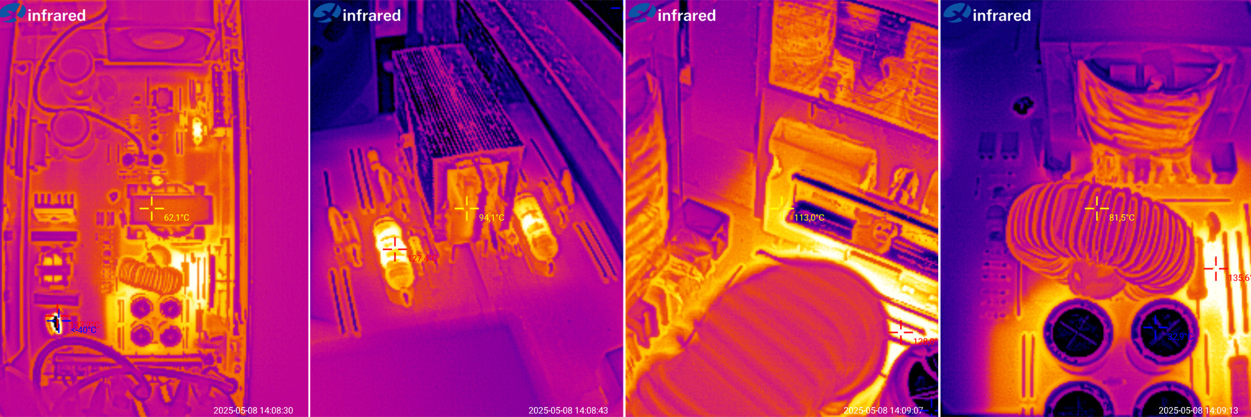
At 45 A — transformer: 62 °C, excellent; transistors: 94 °C, normal; diode assemblies: 113 °C, rather high but tolerable; output inductor: 81.5 °C, excellent.
It's clear that 51 A is an overload for this power supply, since it runs quite normally at 45 A. Yes, the diode assemblies get a little hot, but the other components are operating within normal limits. I think it can easily handle 40–42 A continuously.

Conclusions.
500 W model: excellent ripple performance and high output power, but only for short periods. Over longer runs, it shuts down at currents above 30–32 A. The problem is poor contact between the heat spreader plates and the components; I think things would be better if the plates made full contact. Better still, the manufacturer could have used finned heat spreader plates, like in the 800 W model. The cost difference would be negligible, but the improvement would be substantial. On the plus side, it has thermal protection that does a very good job of preventing overheating.
600 W model: ripple performance is worse, and it feels like the unit simply can't handle the claimed 50 A. The temperatures confirm this: at 51 A, it clearly overheats. But reducing the load by just 10% brought the temperatures back to normal. In practice, it's a decent 500–550 W power supply. Two things I didn't like: the output voltage varies noticeably with load current, and the 100 Hz ripple is high. The first is probably due to an incorrectly chosen feedback pickup point and isn't too critical; the second isn't entirely clear to me.
In short, both models have their drawbacks, though the first one's are easy enough to fix by installing proper heat spreader plates. The second one is more complicated, but I still think it’s quite solvable.
That’s all for today. I hope this was useful, and thanks to Vitaly for providing the power supplies for testing. I hope that by working together we can improve the quality of Chinese power supplies, at least a little :)
They left me with mixed feelings: not bad, but with a few “caveats.” As always, more in the review.
A reminder: to keep up with new posts on the blog, I recommend following me on Instagram. I’ll post notifications about new articles there and might also share something interesting - link to my account
You can also subscribe to updates and new articles on the Telegram channel - https://t.me/KirichBlog
I probably won’t have anything radically new to say today. Like most Chinese products, these have their shortcomings, but the process of tracking down and prodding various factories to make changes to their products continues, so I think some reviews will get a follow-up.
I have to say, though, that surprisingly, Chinese manufacturers are willing to listen and try to improve their power supplies based on some of my recommendations, which is encouraging. Unfortunately, in my dealings with another manufacturer—the one that makes electronic loads—they’ve shown an impressive degree of stupidity. But never mind, I’m not giving up :)
So, here are two power supplies in front of me: one in a box, the other looking pretty :)
The power supplies themselves aren’t anything special: one is rated at 500 W, the other at 600 W. There is one small oddity, though: the 500 W model is rated for 40 A, which works out to 480 W, not 500. But that’s a minor detail. The product page actually lists the power correctly as 480 W.
The 500 W model measures 215x115x50mm. The 600 W model is noticeably larger, especially in thickness: 240x124x66mm.
The output voltage is adjustable, and there’s a terminal block with a cover. The output is split across three terminals for each polarity, and I recommend using all the terminals when running at maximum load.
I’d like to say the insides of these power supplies are very similar, but they aren’t. Despite the relatively small difference in power, they’re quite different inside—in the PCB material and color, as well as the layout. The only thing they really have in common is the topology.
I’ll start with the lower-powered model, PTA-600W-12V - link.
This model looks very much like the most common power supply in this type of enclosure. I wouldn’t be surprised if there were millions of them. The green PCB is a little unusual, as is the fact that it seems to be fiberglass rather than phenolic paper. I’ve rarely seen green boards in power supplies like this; usually they’re either very low-power units or, conversely, very powerful ones.

The PCB is double-sided, which is also fairly uncommon in power supplies like this. A board like that is usually more expensive, too.

Interestingly, it has a proper input filter, including not just an inductor and a thermistor, but also a pair of X capacitors and even a varistor.
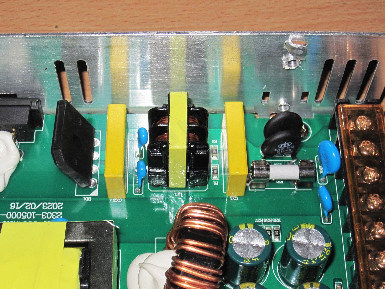
1. A varistor rated for 470 V peak, a standard value.
2. There are also small Y capacitors tucked between the inductor and the X capacitor.
3. This is a serious design flaw. The designers deserve a smack on the knuckles for this one. Remember: the varistor must always be placed after the fuse!!!! Here, you can clearly see that the varistor is effectively connected straight across the input.
4. The input capacitors are from the same mysterious manufacturer as those in the power supplies from another review. Their stated capacitance is 680µF.
Interestingly, there’s a lot of unused space—literally a section of the PCB with no components on it.

1. The power supply section for the PWM controller and... the fan. At least, I couldn’t see a temperature sensor.
2. The PWM controller itself, a KA3845.
3. PTA18N45 transistors, rated for 18 A and 450 V.
4. Two optocouplers are tucked away near the transformer, which usually indicates an output overvoltage protection circuit.
The power supply uses a half-bridge topology. Nothing new here.

1. The output section has a completely conventional layout: a pair of diode assemblies, an inductor, and several capacitors.
2. The diode assemblies are different: 50 A on the left, 40 A on the right. The voltage rating is the same, 100 V.
3. There are four 3300µF capacitors. In my view, that’s a generous margin for this topology and output current.
4. Feedback and overvoltage protection circuit.
The board is single-sided, so the underside is empty and there are no electrical safety concerns—except for the incorrectly installed varistor, which I mentioned earlier.

The input filter capacitance is 247 µF, which means the capacitors are about 500 µF each—clearly less than the stated 680. In fact, even 340 µF (two 680 µF capacitors in series) is a bit low for 500 W, and here they've gone even lower.
The output side is fine, with about 14,000 µF in total.
The output voltage adjustment range isn't very wide, roughly 11.2 to 12.8 V, and I wouldn't say the adjustment itself is smooth, though that's not a big deal.
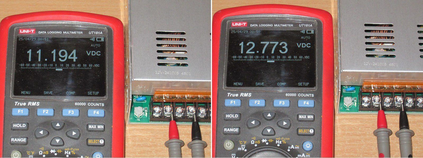
For the tests, I used a pair of electronic loads, an oscilloscope, a multimeter, a wattmeter, and a thermal camera. One load would have been more than enough in terms of power, but its 40 A limit is a significant restriction, so I had to use two.

The protection is set rather crudely, and the controller starts reducing the voltage at around 54–55 A, which is clearly too high for a 40 A power supply.
Efficiency was measured from 2 to 50 A in 2 A increments and peaked at about 84%. That's not very high, but it's pretty typical for a Chinese power supply.
I have no complaints about the high-frequency ripple at all: less than 150 mV at 40 A is very good. Here are the results with no load and at 13, 26, and 40 A.

The low-frequency component is also fine. Yes, there's some ripple at 100 Hz, and the filter capacitance is low, but the amplitude is still well within acceptable limits.
Next up was supposed to be a load test, but it didn't quite go as planned.
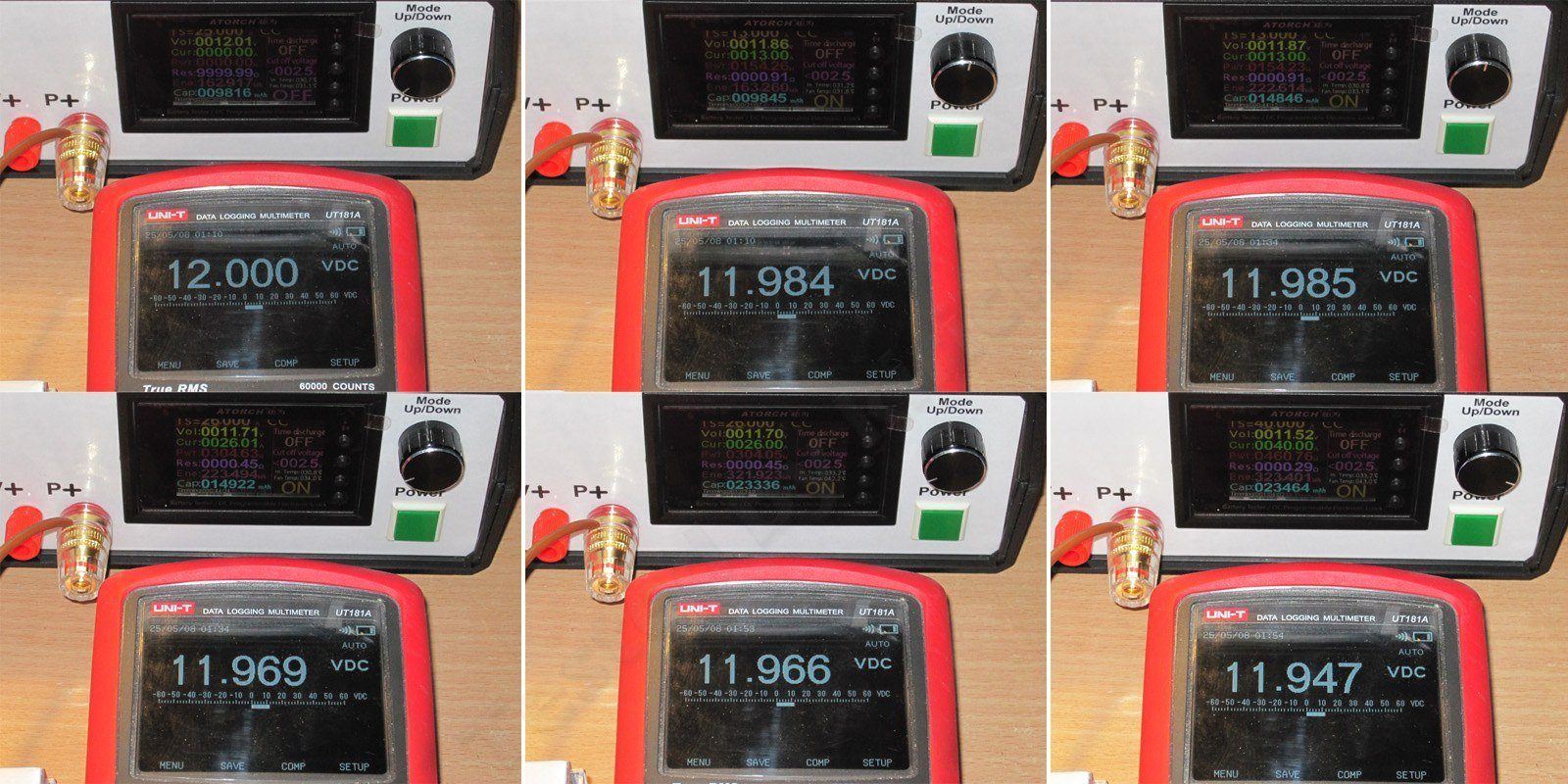
1. Exactly 12 V with no load.
2. At 13 A, it was 11.984 V when cold—fine.
3. After warming up at 13 A, it was 11.985 V—perfect.
4. At 26 A, it dropped to 11.969 V—fine.
5. After warming up at 26 A, it was 11.966 V—perfect.
6. I raised the current to the maximum of 40 A; it dropped to 11.947 V—excellent.
But I set it to 40 A, went out for a smoke, and heard the load slowing down its fans. Something was clearly wrong.
When I came back, I saw that the power supply had shut down. I tried again, and it shut down again. I lowered the current to 39 A, then 35 A, then 32 A, and only at 30 A could the power supply run continuously.

Temperatures at 13 and 26 A. Nothing alarming, really, except that one of the diode assemblies is running hotter than expected.
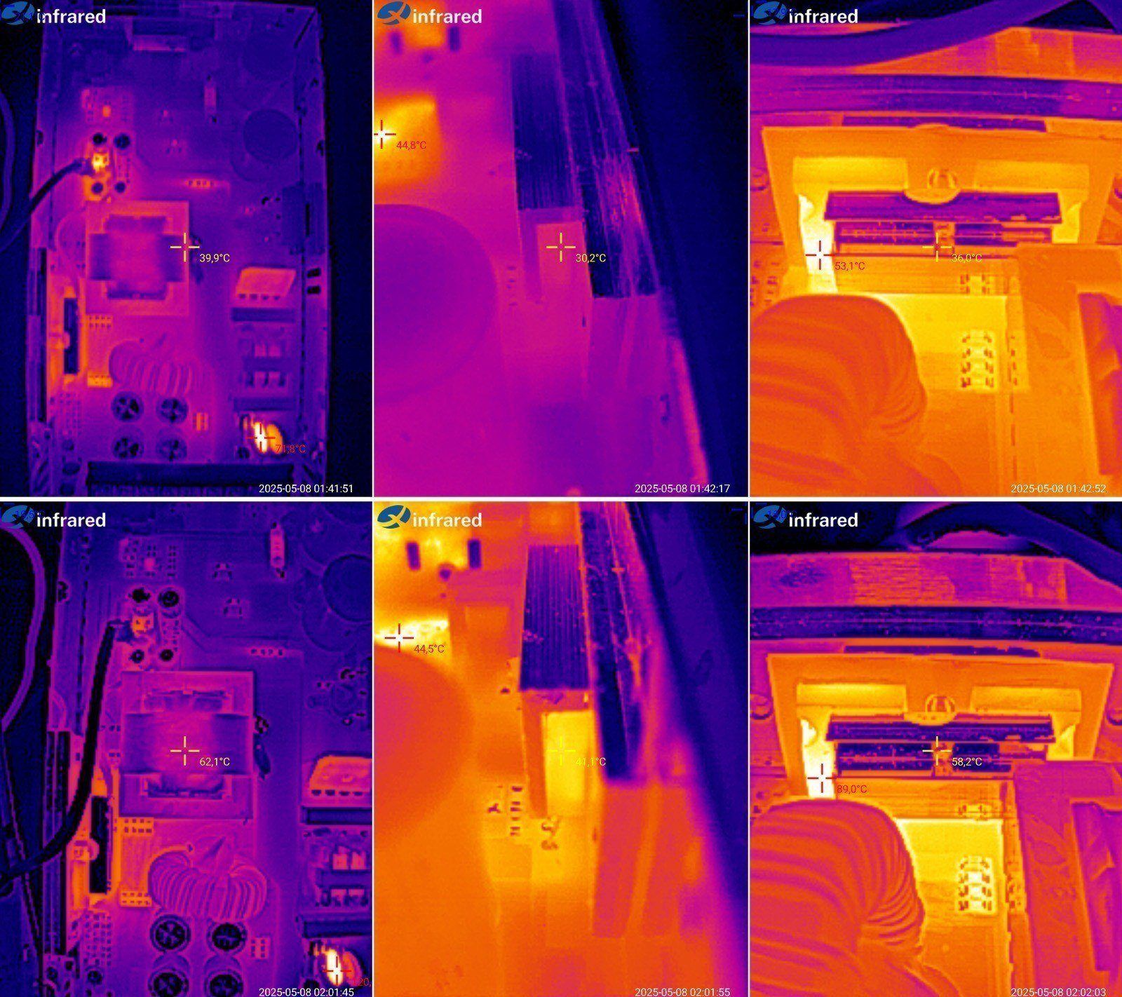
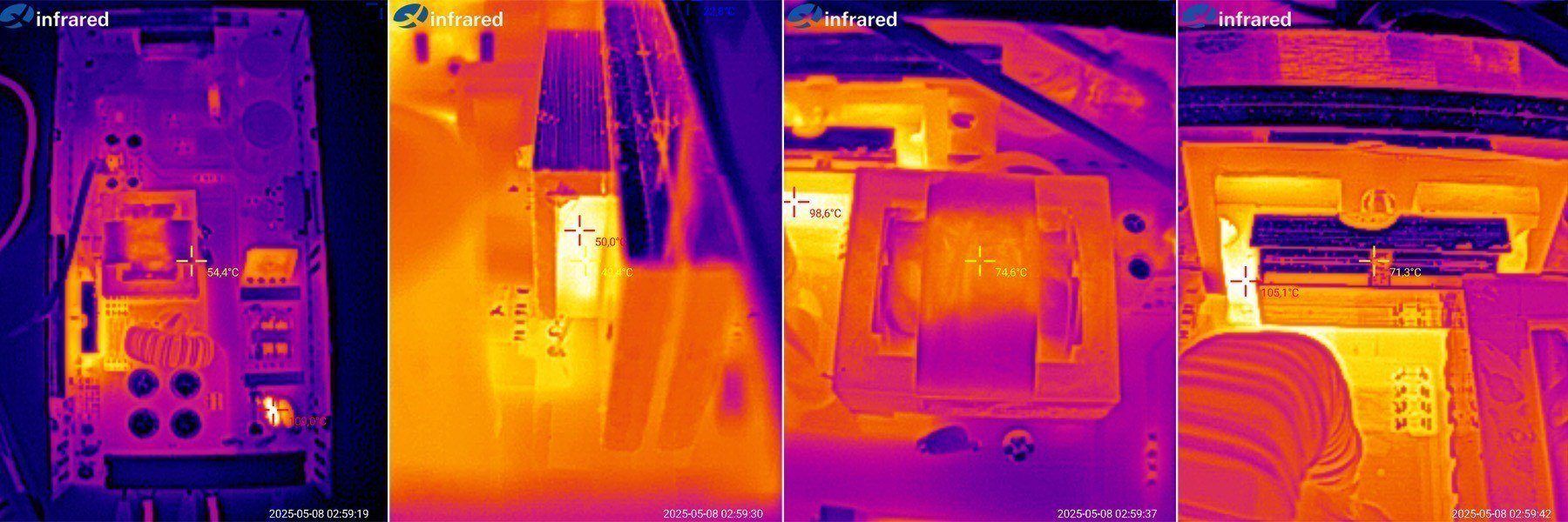
At 30 A, everything was also fine except for the temperature of that same diode assembly. 105 °C is a bit much, though not critical.
On the other hand, 30 A is a long way from the maximum of 40 A.
I took a closer look at how the power components were mounted and found a gap between the heat spreader plate and the case. Actually, not just a gap—a GAP. It's there for both the diodes and the transistors, although the transistors weren't overheating.
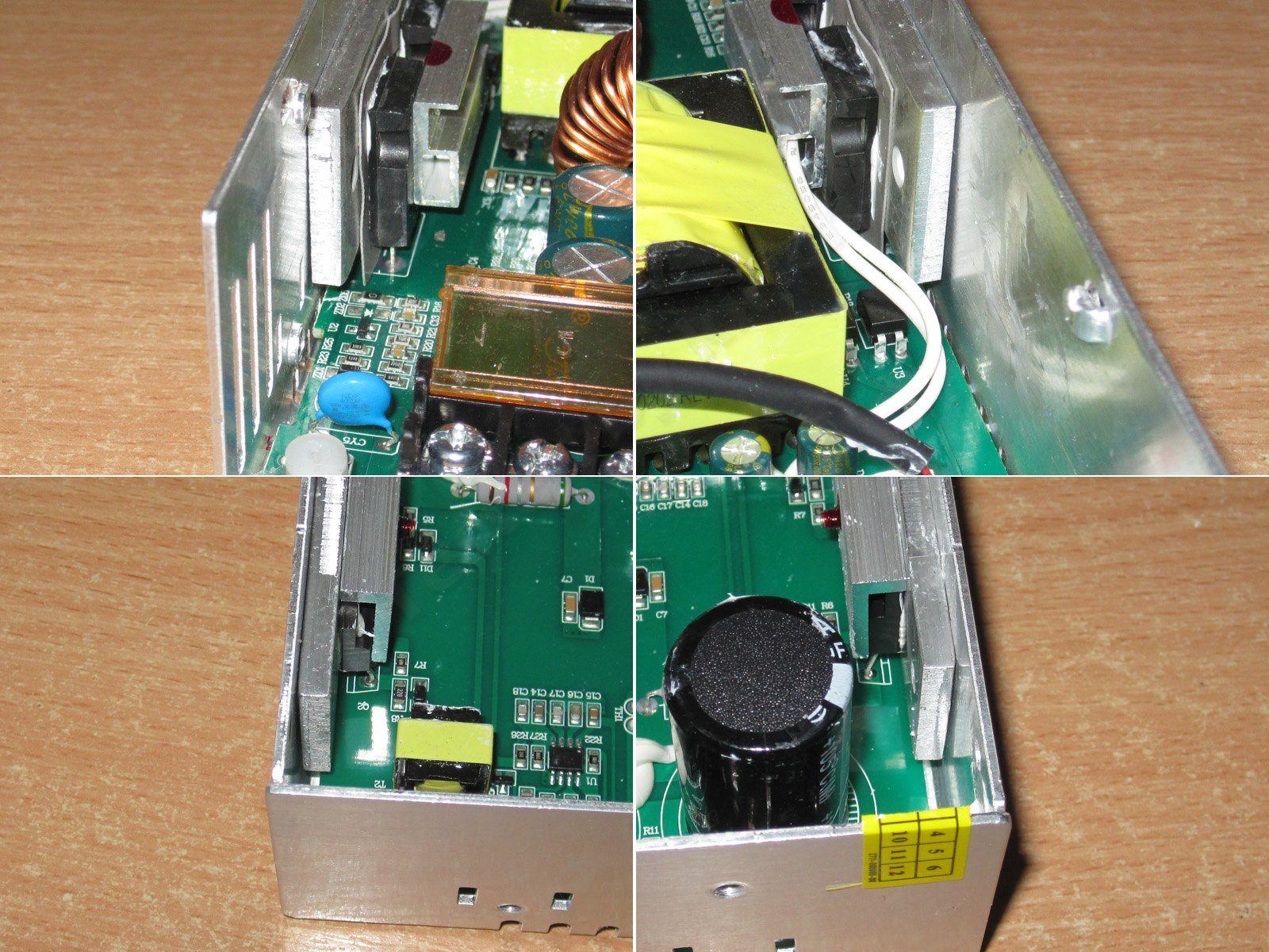
I removed the plates and, while I was at it, took the power supply apart out of curiosity. I also checked the thermal protection: there's an 85 °C thermal switch that cuts power to the PWM controller. The thermal switch itself is installed inside the diode clamp bar.
I held it in place and realized that the case was slightly bent around the mounting points. I tried to straighten it, then applied thermal paste between the plate and the case around the diodes and transistors and put everything back together, but I can't say anything looked visibly different.
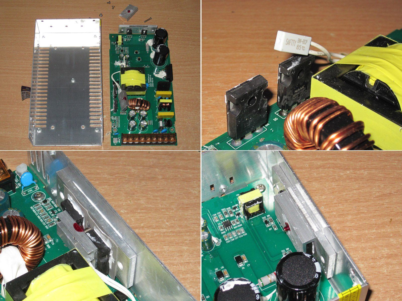
I started with a half-hour test at 26 A—fine. Then I raised it to 32 A, also without any issues. But as soon as I increased the current to 35 A, it shut down due to overheating again.
I stopped experimenting there, since I don't see any point in investigating the cause. I'll pass the information on to the factory.
And now I'm of two minds about it. On the one hand, it has thermal protection, which is great: you simply can't burn the power supply out. On the other hand, because of the cooling issues, it can only deliver 75% of its rated power continuously. It can still supply 40 or even 50 A, but only until the protection kicks in.
I should also mention that the fan is fairly quiet. It appears to be rated for 12 V, 0.16 A.

The second power supply, PTA-600W-12V, link
The layout, board material, and color are all different. And unlike the previous model, which used SMD components, this one uses only through-hole components.

The inside looks extremely simple—almost as if they forgot to install some components :) Judging by its appearance, it uses the same topology as the previous model: an asymmetric half-bridge.
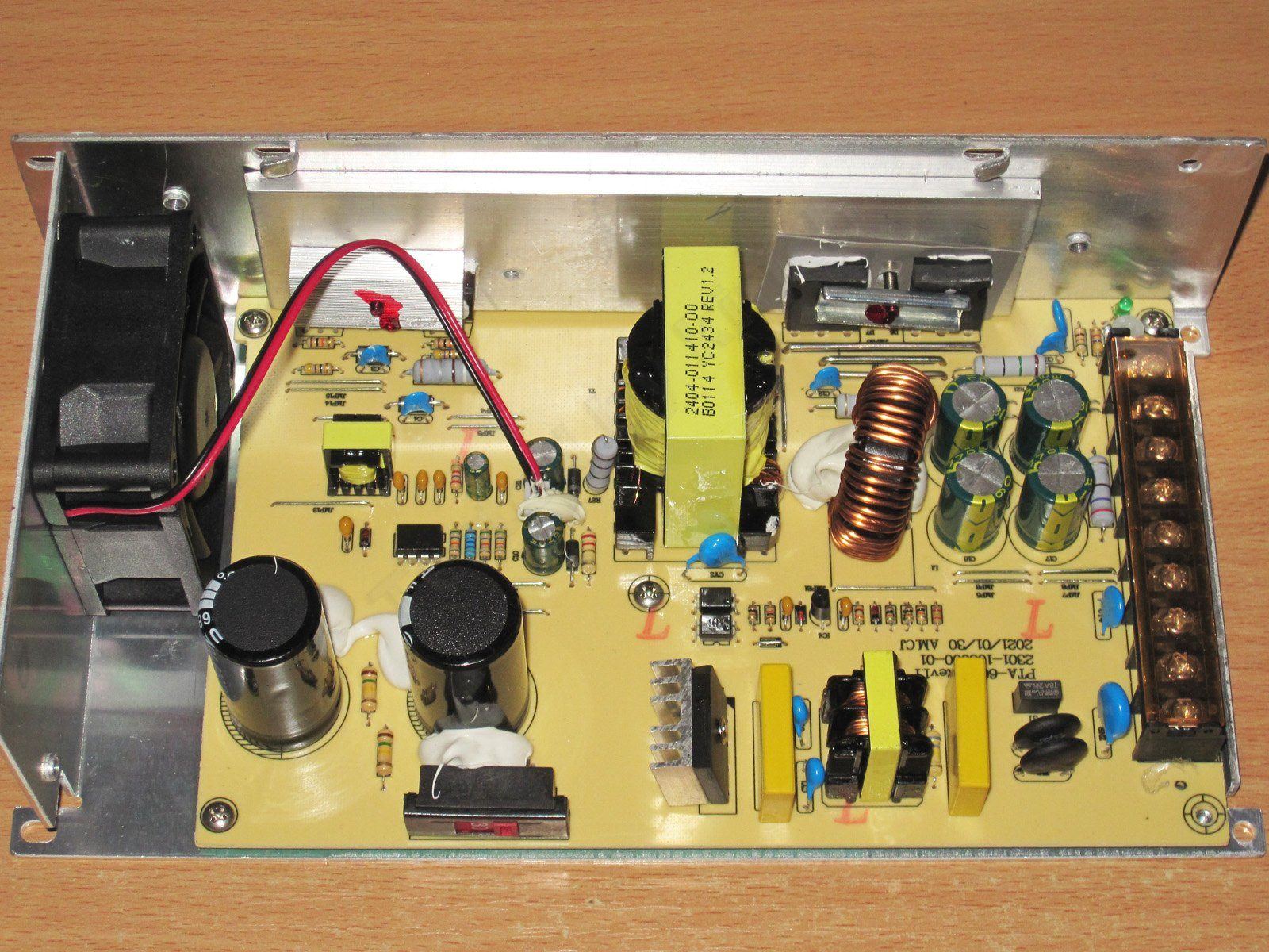
To be fair, when I saw the large polished metal case, I expected to find something inside like what I saw in the 800-watt power supply. At least they look identical on the outside, but the insides are completely different—in other words, these are power supplies in entirely different classes.

The input filter is the same as in the previous model, including the varistor before the fuse. The only change is that a heatsink has been added to the bridge rectifier.

As in the previous model, an output overvoltage protection circuit has been added alongside the main feedback loop.
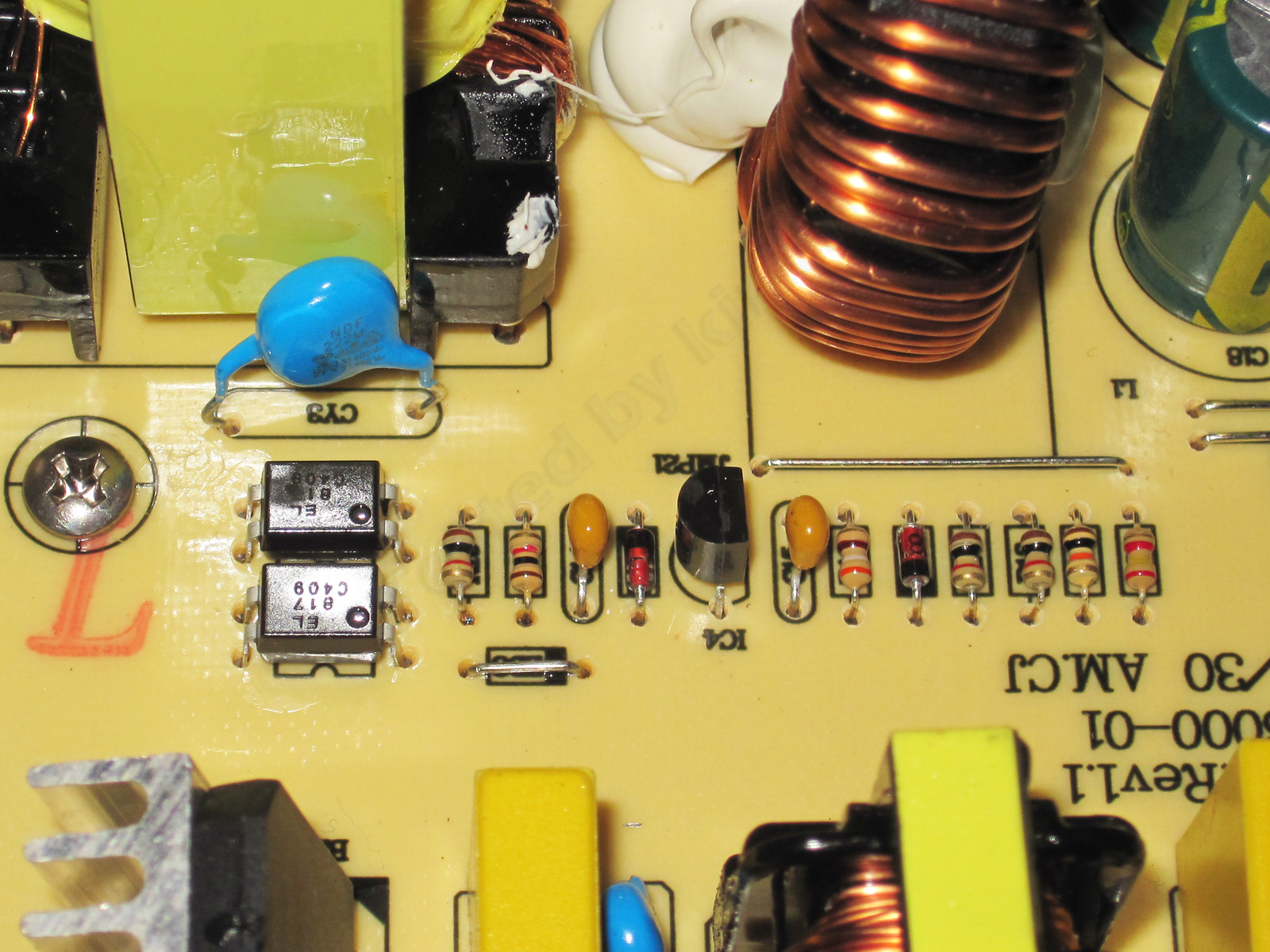
The PWM controller is a UC3845, essentially the same as the KA3845 in the previous model.
The transistors are more powerful here: 20N50, rated at 20 A and 500 V, versus 18 A and 450 V in the previous model.
The output has the same inductor and a pair of diode assemblies, but here they're both rated for 60 A, rather than 60 A and 40 A.
Another difference is that the previous power supply had two small heat spreader plates, while this one has a single large one covering almost the entire side of the unit.

The transformers look similar in size, but they're actually different. The 500-watt version measures 45x41x13.5, while the 600-watt version measures 43x43x15 mm.

The PCB clearances are adequate, so I have no concerns about the safety of the layout.
The circuit design does have a few changes, though. The previous model had voltage regulators in the fan and PWM controller supply circuits; this one doesn't. Interestingly, that makes the fan quieter. It runs quietly up to a load current of about 4–5 A. Increase the load current, and it reaches full speed at around 7–8 A.
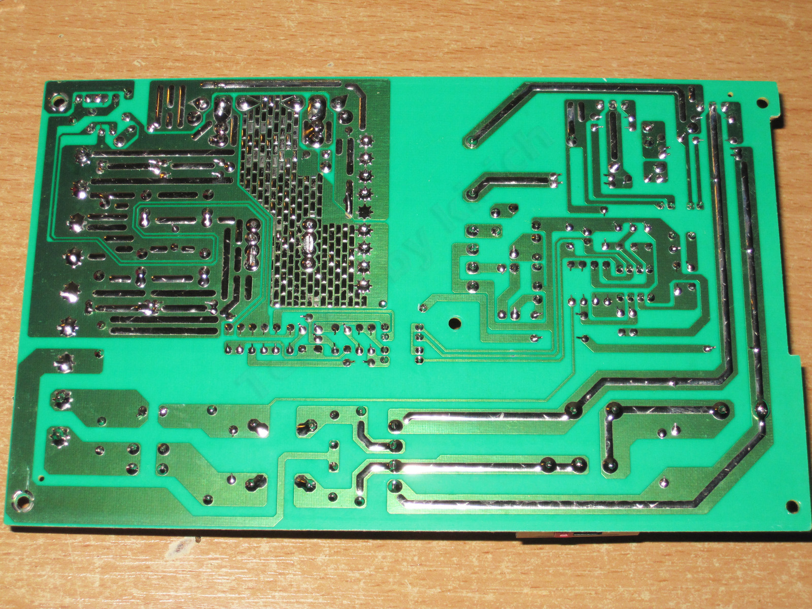
The input capacitors are another disappointment: their actual capacitance is about 500 µF instead of the stated 680 µF. As you can imagine, that's an even bigger problem here, since this power supply is more powerful.
The output capacitors are fine—in my opinion, they even have some headroom.
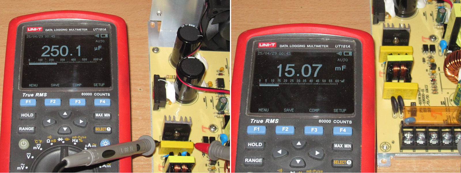
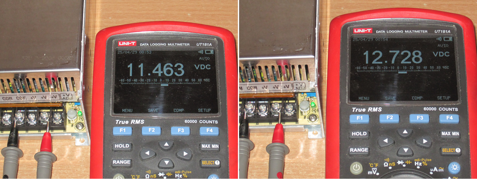
The output voltage adjustment range is slightly narrower than on the 500-watt version: 11.45–12.7 V.
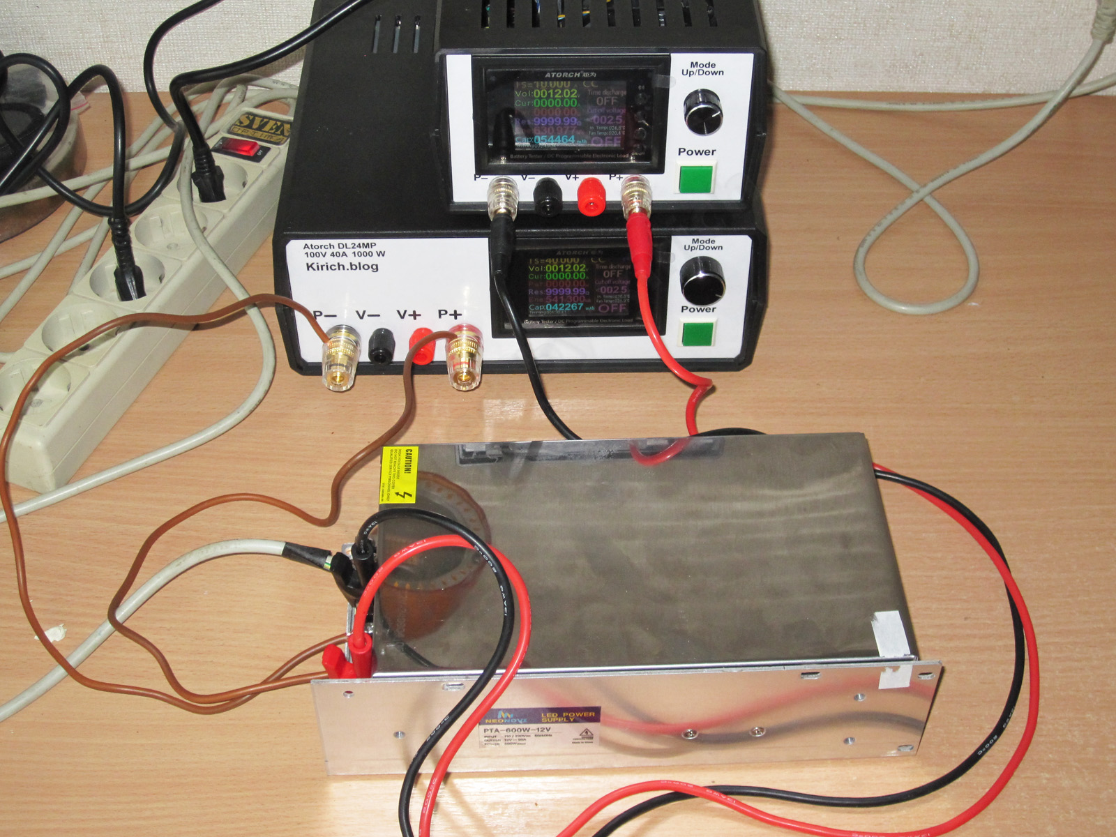
I used two electronic loads for the tests as well. The lower one was the main load; the upper one was added when 40 A wasn't enough. The upper load alone would have been sufficient for a 600-watt unit, but unfortunately it only goes up to 40 A.
I tried to determine the protection trip point, but this protection doesn't have a fixed threshold; it just reduces the output voltage.
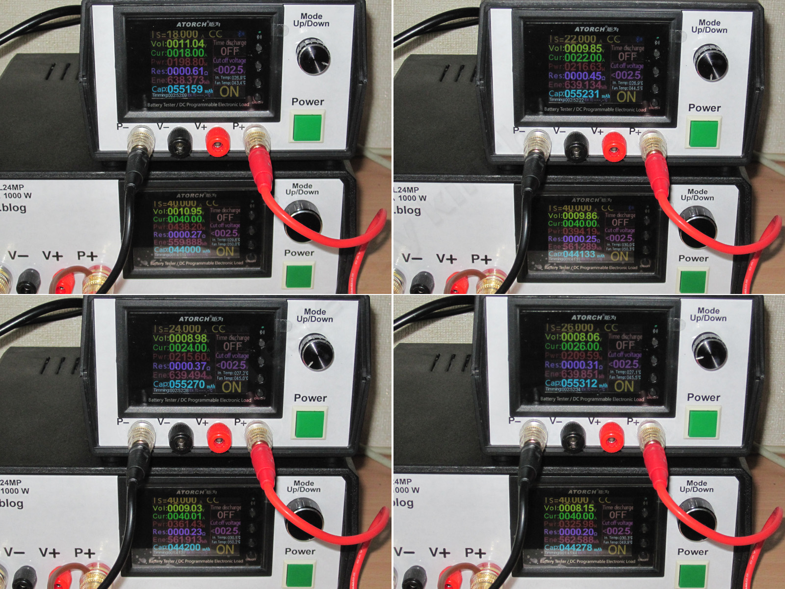
At 58 A, everything is stable. Around 11 V is fine: that's the voltage drop across the power supply itself plus the drop in the wires. At 60 A, the voltage starts to sag; at 62 A, the drop is clearly noticeable. Next, I gradually increased the load current to 64 and 66 A, but the power supply didn't shut down. I didn't risk increasing the load current any further; I wanted to run some more tests :)
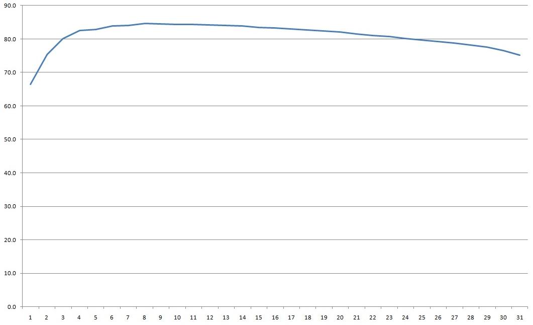
I measured efficiency from 2 to 62 A in 2 A increments. The results were about the same as for the previous unit. At 60 and 62 A, the voltage dropped slightly, but that's an overload condition, so it's normal.
Ripple was measured with no load and at currents of 17, 34, and 51 A. I connected the probe directly to the terminals, just as I did when measuring the previous power supply.
The high-frequency ripple is somewhat worse here. The previous unit had up to 150 mV, probably closer to 130 mV, while this one reaches about 250 mV at maximum load. That's perfectly normal given its power, though the difference is a little surprising.
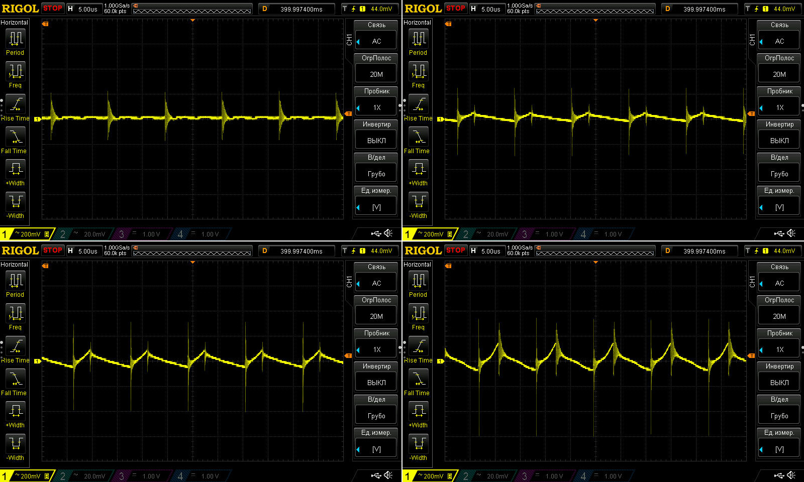
The low-frequency ripple is much worse, though: the 100 Hz ripple is quite pronounced. That's even stranger, since the two power supplies use the same circuit design, the same capacitor values, and almost identical transformers. Maybe something went wrong with the PWM controller's surrounding components or the PCB layout.

I had to improvise to check the thermal performance, since removing the cover while the unit was running wasn't very convenient. In the end, I made a makeshift cover to simulate the original one.
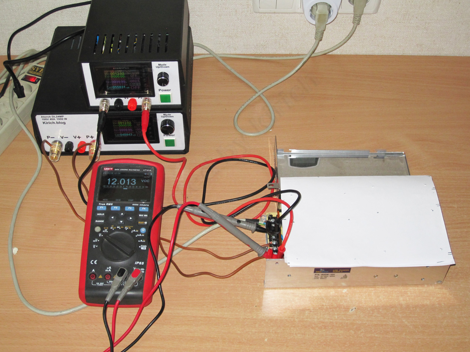
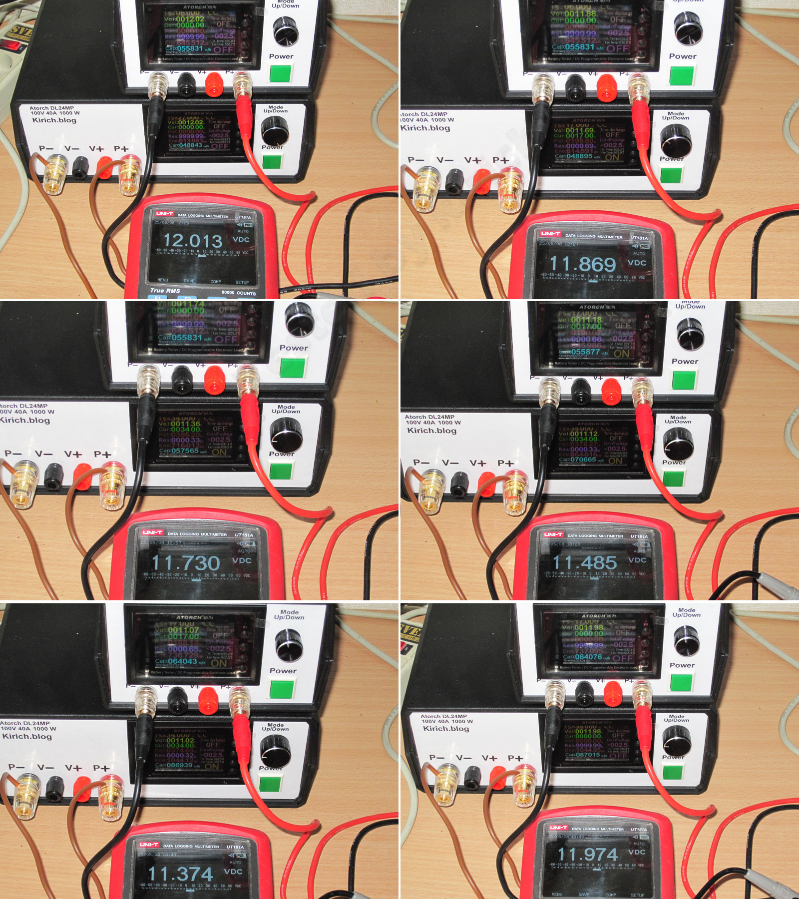
First, though, here's how the output voltage changes with load current and temperature.
1. No-load voltage with the power supply cold
2. 17 A load
3. 34 A load with the power supply warm; the voltage has dropped by about 0.3 V
4. 51 A load with the unit warmed up; the voltage has dropped by about 0.55 V
5. 51 A load with the power supply hot; the voltage is now 0.65 V below its initial value, which is quite a difference.
6. No-load voltage with the unit warmed up; the difference is about 40 mV.
As you can see, the voltage barely depends on temperature, which is very good. But it depends heavily on the load current. I think the feedback pickup point was chosen incorrectly. In practice, the unit's output voltage drops by about 5%, which is within spec, of course, but right at the lower limit. One option would be to set the voltage to 12.3 V to begin with, so it would be 11.7 V at maximum current, bringing the variation down to 2.5%.
The test went like this:
30 minutes at 17 A
25 minutes at 34 A
30 minutes at 51 A
There's no point listing the results at 17 A; everything was fine. Here are the results at 34 and 51 A.
34 A — transformer: 46 °C, excellent; transistors: 58 °C, excellent; diode assemblies: about 80 °C, rather high; inductor: 56 °C, excellent.
51 A — transformer: 74 °C, excellent; transistors: 122 °C, overheating; diode assemblies: about 135 °C, overheating; inductor: 101 °C, tolerable.
The power supply clearly started overheating badly. I suspect it simply went beyond its normal operating range. The output inductor may be incorrectly specified; it's the same one used in the 500 W model. This could also have affected the ripple.
To check my theory, I reduced the load current to 45 A, about 10% lower, and ran it for another 8 minutes or so.
The results changed dramatically.
At 45 A — transformer: 62 °C, excellent; transistors: 94 °C, normal; diode assemblies: 113 °C, rather high but tolerable; output inductor: 81.5 °C, excellent.
It's clear that 51 A is an overload for this power supply, since it runs quite normally at 45 A. Yes, the diode assemblies get a little hot, but the other components are operating within normal limits. I think it can easily handle 40–42 A continuously.
Conclusions.
500 W model: excellent ripple performance and high output power, but only for short periods. Over longer runs, it shuts down at currents above 30–32 A. The problem is poor contact between the heat spreader plates and the components; I think things would be better if the plates made full contact. Better still, the manufacturer could have used finned heat spreader plates, like in the 800 W model. The cost difference would be negligible, but the improvement would be substantial. On the plus side, it has thermal protection that does a very good job of preventing overheating.
600 W model: ripple performance is worse, and it feels like the unit simply can't handle the claimed 50 A. The temperatures confirm this: at 51 A, it clearly overheats. But reducing the load by just 10% brought the temperatures back to normal. In practice, it's a decent 500–550 W power supply. Two things I didn't like: the output voltage varies noticeably with load current, and the 100 Hz ripple is high. The first is probably due to an incorrectly chosen feedback pickup point and isn't too critical; the second isn't entirely clear to me.
In short, both models have their drawbacks, though the first one's are easy enough to fix by installing proper heat spreader plates. The second one is more complicated, but I still think it’s quite solvable.
That’s all for today. I hope this was useful, and thanks to Vitaly for providing the power supplies for testing. I hope that by working together we can improve the quality of Chinese power supplies, at least a little :)
This page was found when searching for:
2
2
The figures from this review are in the measurement database: Power supplies
Calculate manuallyAll calculators
Discounted products
You may be interested in



Discounted products
Support the project
All the content on the site and the advice are free, but we’d be grateful for your support of the project and the channel!
Comments2
Discuss on the forumHave a question or some experience to share? Discuss the article with the author and readers: the forum is a convenient place to share schematics and photos.
Go to the forumOnly registered readers can comment. It takes a minute to sign up, and you can log in with the same account you use on the forum.
Log inRegister
Comments are published in their original language.