
24 V 10 A power supply, a mixed bag
$23.01
A reminder: to keep up with new posts on the blog, I recommend following me on Instagram. I’ll post notifications about new articles there, and maybe write about other interesting things too - link to my account
You can also subscribe to updates and new articles on the Telegram channel - https://t.me/KirichBlog
The power supply currently costs $23 at the link, supposedly on sale. When I ordered it, the price was around $19; with coupons, it came to about $14, which I think is its actual worth. Why? Because for about the same price you can get a pretty high-quality 24 V power supply, with a soft start and adjustable output voltage, and rated for 300 W rather than 240 W. Unfortunately, it wouldn’t work for my project because of its size, so I bought the one reviewed here.
It’s built into a U-shaped aluminum chassis, a standard design for enclosed power supplies. There are versions rated for 36 V at 7 A and 24 V at 10 A.
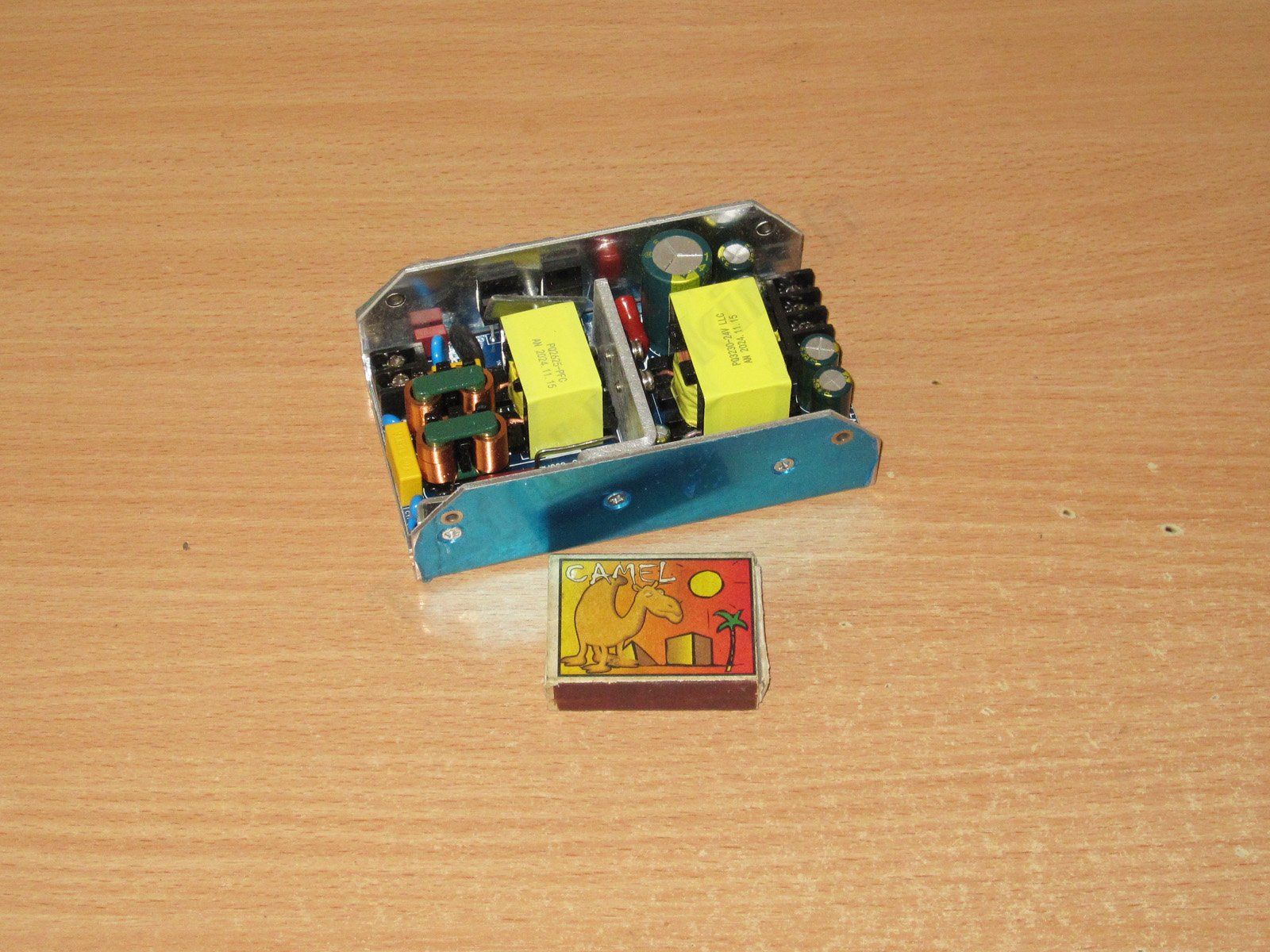
The components are packed in pretty tightly, and the power supply also has power factor correction, which makes the layout even denser. Still, everything looks reasonably neat.
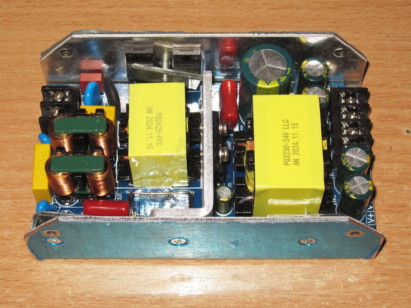
1. The input has a full filter, with a pair of inductors, X and Y capacitors, a thermistor, a varistor, and a fuse. In short, it’s excellent. Well, not quite: for some reason, they fitted a two-terminal input block, so the ground wire has to be attached to a screw on the chassis itself.
2. There’s an SPM-260 marking near the shunt. That’s odd: the power supply is rated at 240 W, not 260 W.
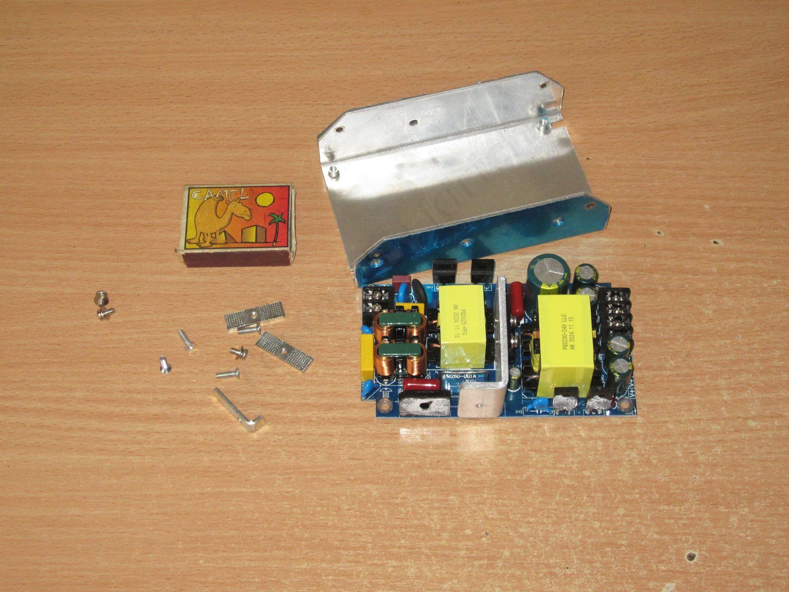
3. The PFC transistor and diode are screwed to the chassis, with thermal paste applied. The PFC bypass diode is next to them.
4. The power supply’s two switching transistors are mounted on a separate heatsink, which is in turn screwed to the chassis. It’s not a very convenient design, either for repairs or just for taking a look. For example, I couldn’t see the markings on those transistors at all.
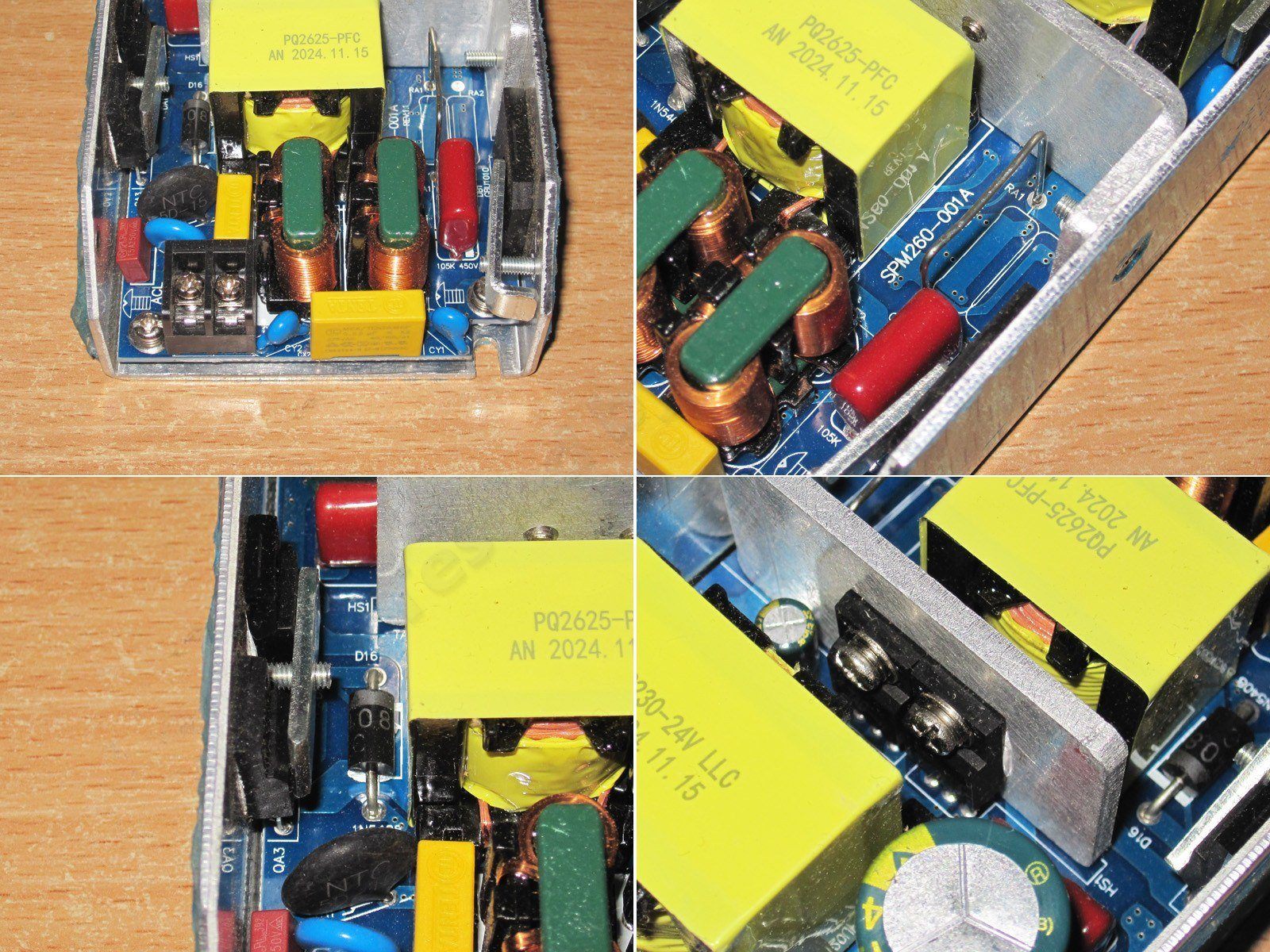
1. On the output side there’s a four-terminal block, the output capacitors, and the high-voltage input capacitor. At first I was suspicious of having the input capacitor so close to the output ones, but it turns out everything is laid out correctly and safely.
2. There are three 1000 µF, 35 V output capacitors. Next to them you can see a pair of output diode assemblies, screwed to the heatsink.
3, 4. The PFC inductor and transformer are well made; both use litz wire for their windings, so I have no complaints here.
The markings make it possible to identify the components and also show that the power supply uses an LLC topology, though essentially in a hybrid inductor-plus-transformer configuration.
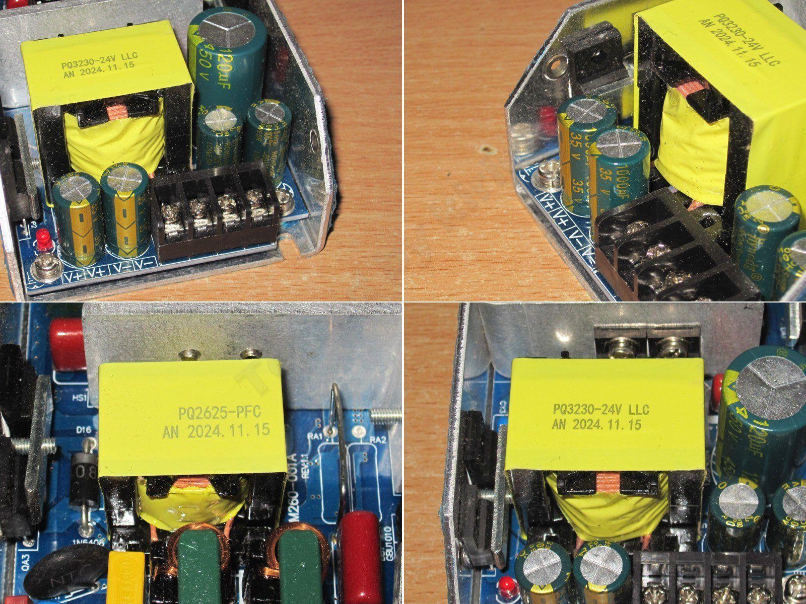
I had to take the unit apart a little to get a closer look. It’s fairly easy to disassemble, and thermal paste is present everywhere it’s needed.
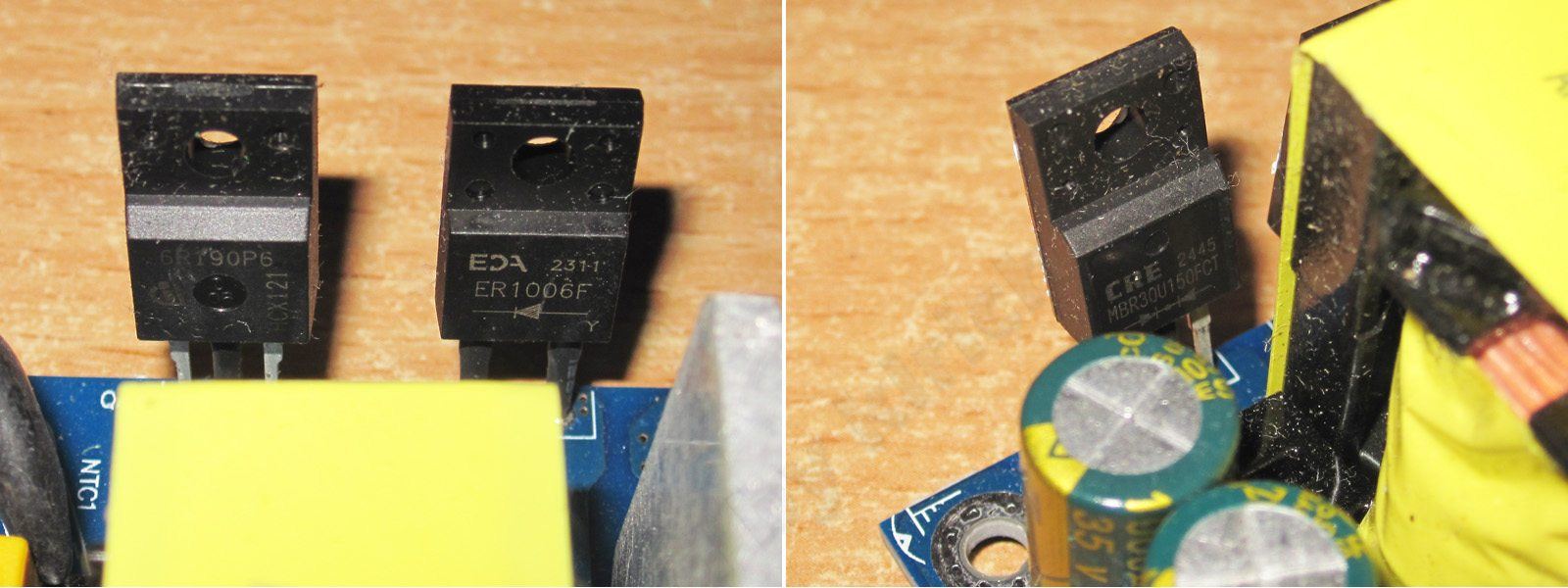
1. The PFC transistor and diode.
2. The output diode assemblies are rated for 30 A and 150 V, which seems like a generous margin for the stated 10 A output.
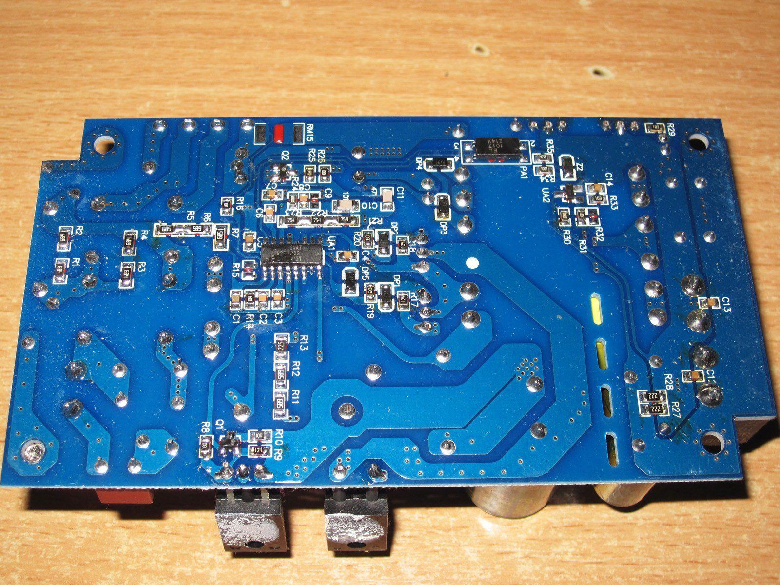
The circuit board is relatively clean, though there’s some dust on it. There was dust on the power supply itself, too. The output capacitors are bypassed with ceramic capacitors, the clearances are adequate, and overall the power supply seems quite thoughtfully designed. There is, however, a significant safety flaw, which I’ll get to at the end of the review.
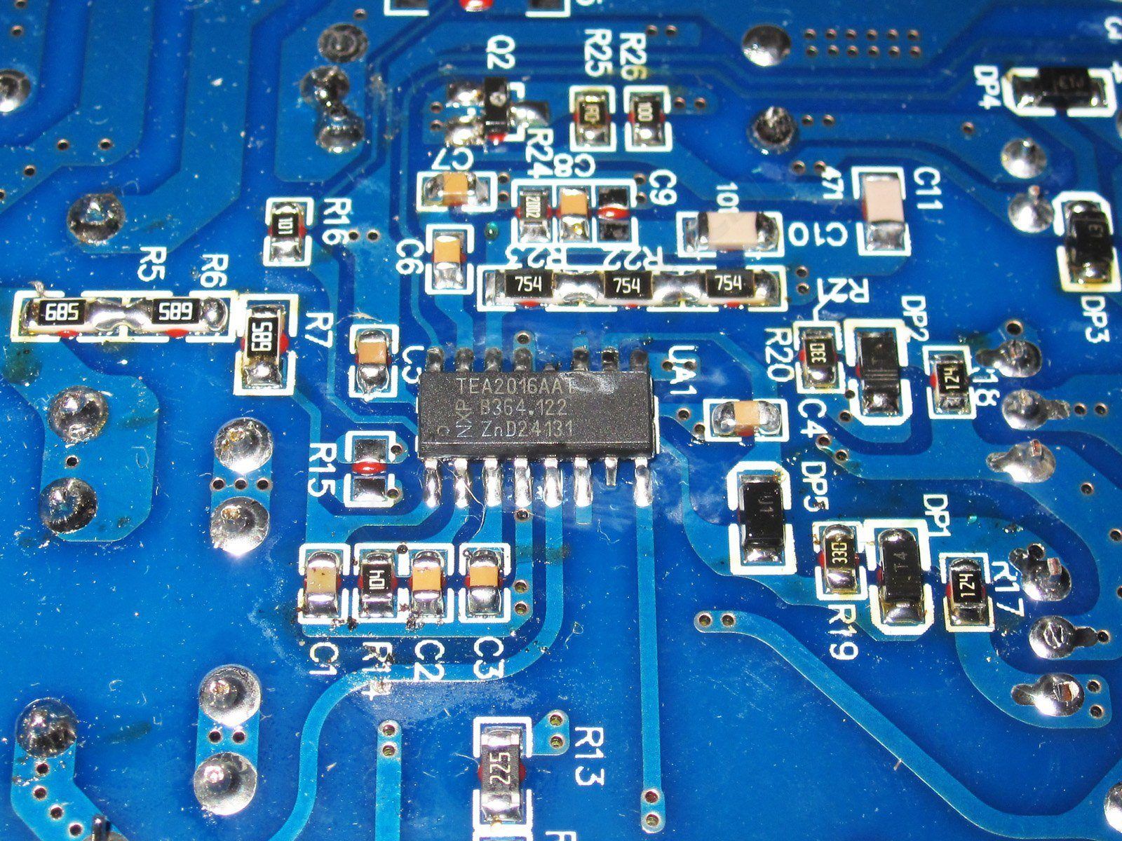
It’s built around the TEA2016 combo PWM controller, which can control both an active PFC stage and an LLC inverter.
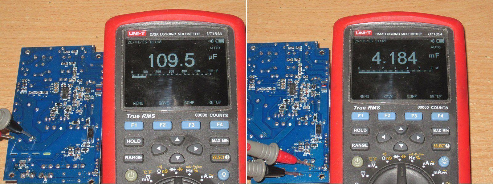
The input capacitor is about 110 µF, not much less than the stated 120 µF. The actual output capacitance is 4000 µF.
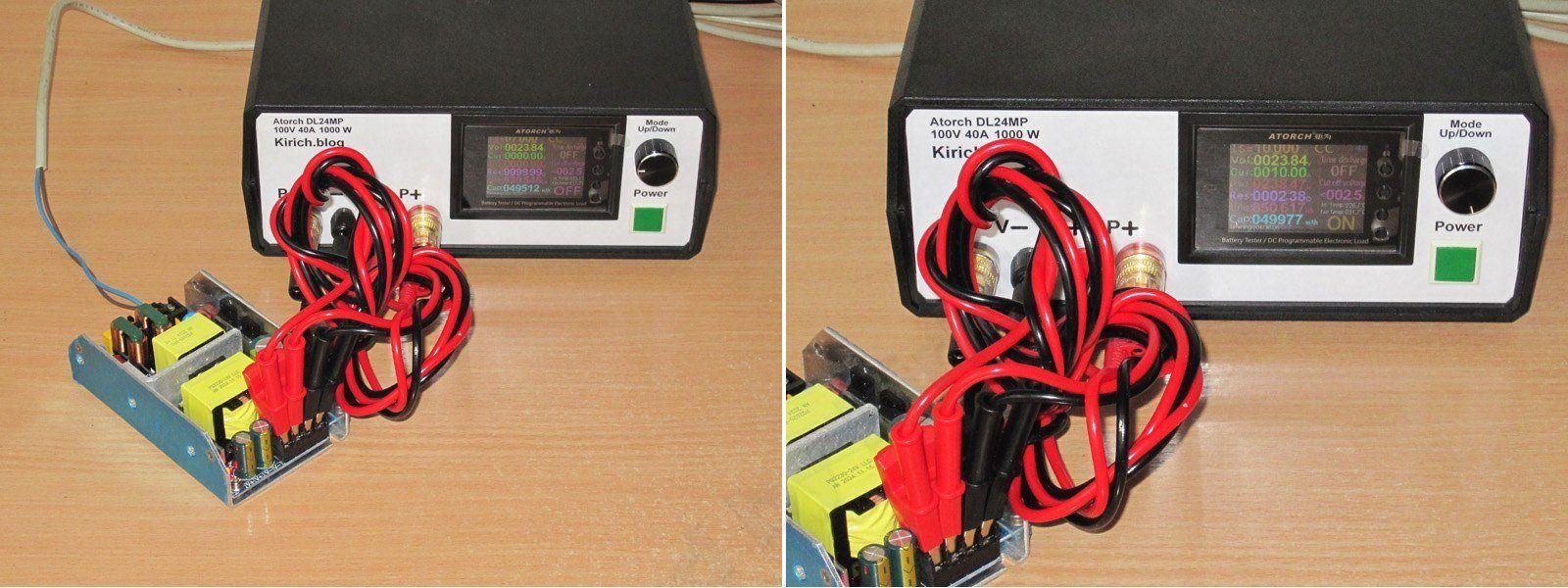
For testing, I used an electronic load based on an Atorch, with a four-wire connection.
I’ll note right away that the output voltage is very stable: 23.84 V both at no load and under full load.
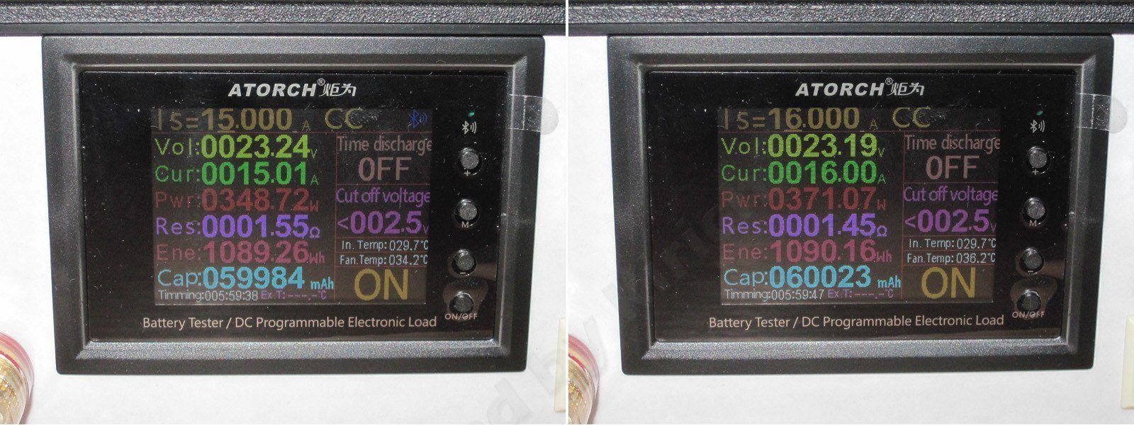
The protection circuits, though, are a real problem. I easily loaded the power supply to 15 A, then 16 A, despite its 10 A rating, and it showed no sign of going into protection.
You can see in the photo that the voltage dropped, but I can’t remember for sure; I think I was using a two-wire connection in this case, so the drop was due to the wires. But that doesn’t change the fact that the overload protection is set far too high.
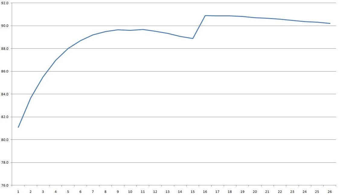
I measured efficiency at currents from 0.5 to 13 A in 0.5 A increments. The results look rather curious: at 8 A, efficiency suddenly jumps by several percentage points. At first I suspected a mistake in my notes—these things happen—but you might make a typo once, maybe twice, but not in a third of the results. Apparently (I haven’t checked), the power factor correction circuit doesn’t start immediately, but only once a certain power level is reached. Either way, it’s quite unusual.
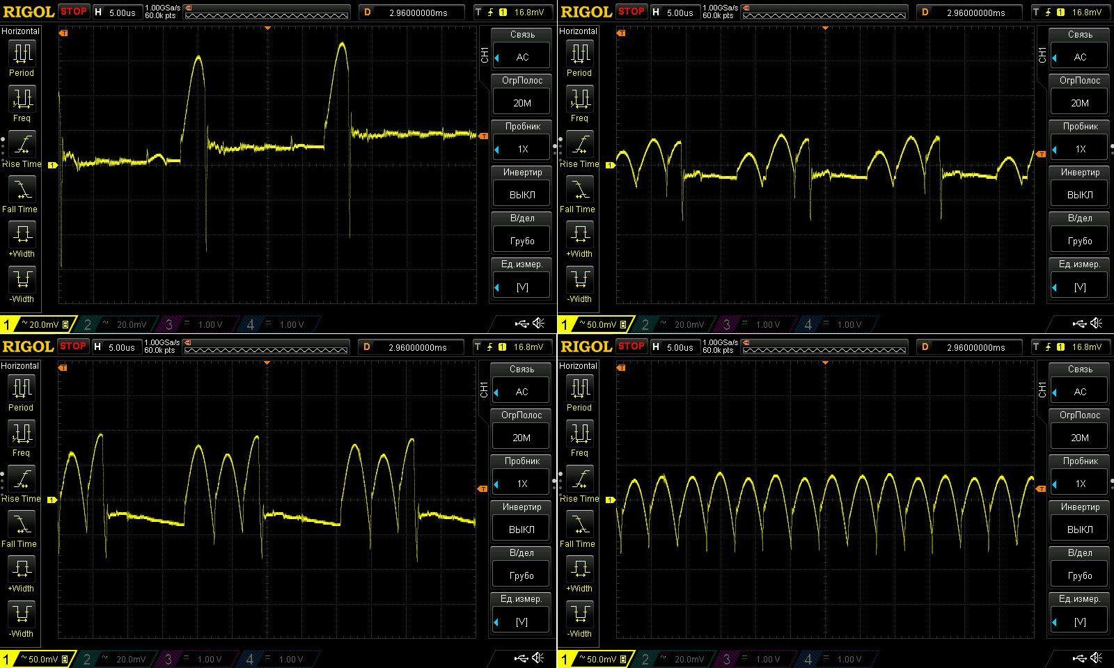
I checked ripple with no load and at currents of 3.3, 6.6, and 10 A.
With no load, it’s usually a straight line, but there are occasional spikes. This oscilloscope capture is set to 20 mV; all the following ones are set to 50 mV.
At 3.3 A, ripple is about 125 mV; at 6.6 A, it’s closer to 170–180 mV. But when I raise the current to 10 A, ripple is actually lower than at 3.3 A. I think this is another quirk of the controller, the same one we saw in the efficiency graph. I’m almost certain ripple increases up to 7.5–8 A, then something switches over and it drops.
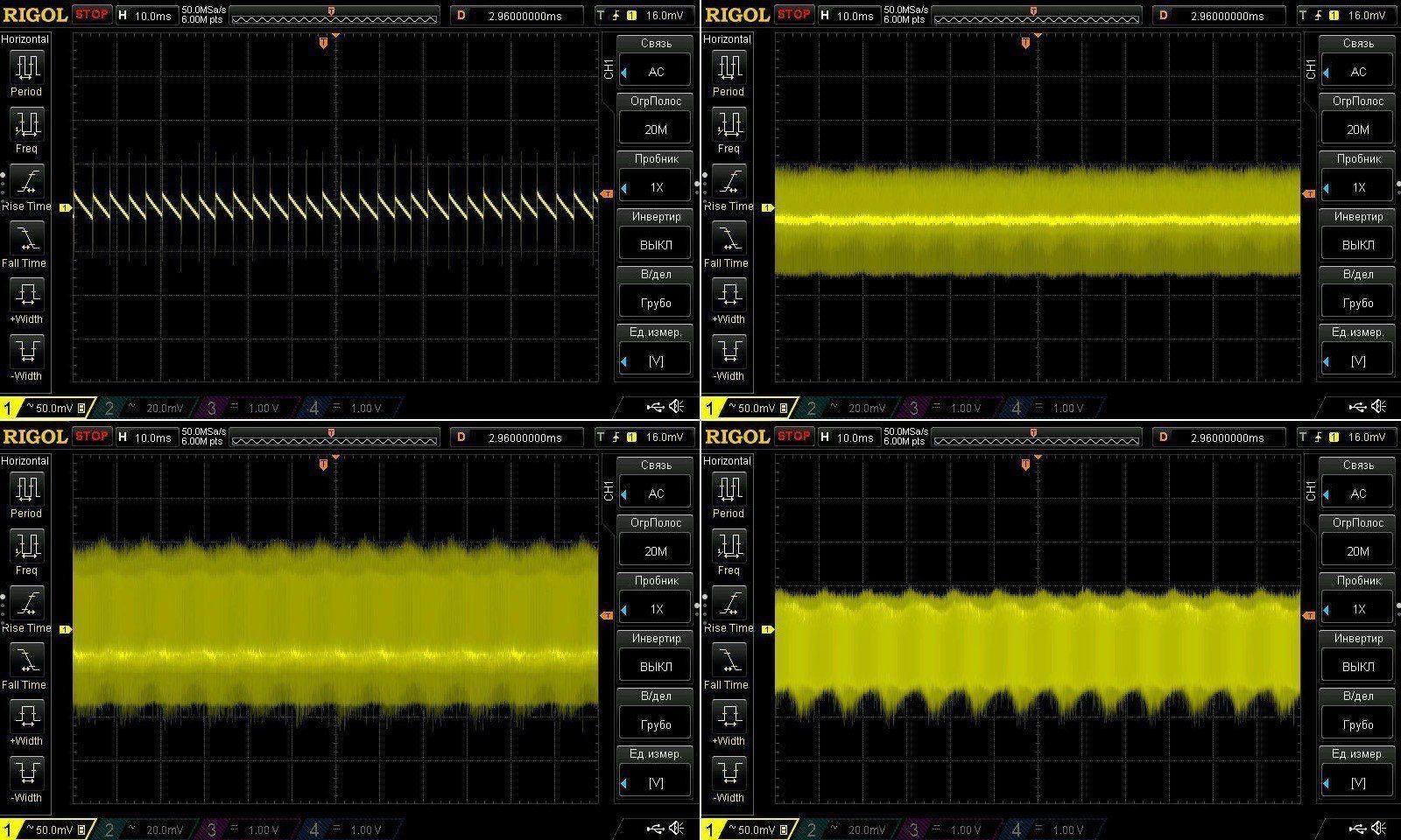
The low-frequency ripple looks similar, and I have no complaints here either. Even if it were 200–250 mV, that would be only about 1% of 24 V, which is perfectly fine.
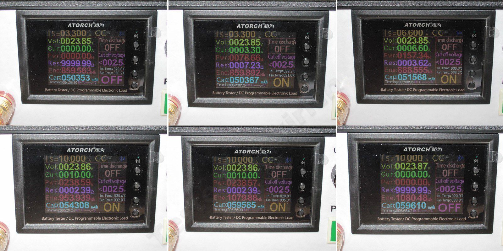
I ran the load test in three modes: 3.3, 6.6, and 10 A. The photos show intermediate stages. Here too, I’ll note the excellent output voltage stability: it changes by just 20 mV across the entire load and temperature range.
The first photo shows the power supply cold and unloaded; the second-to-last shows it hot under 100% load; the last shows it hot and unloaded.
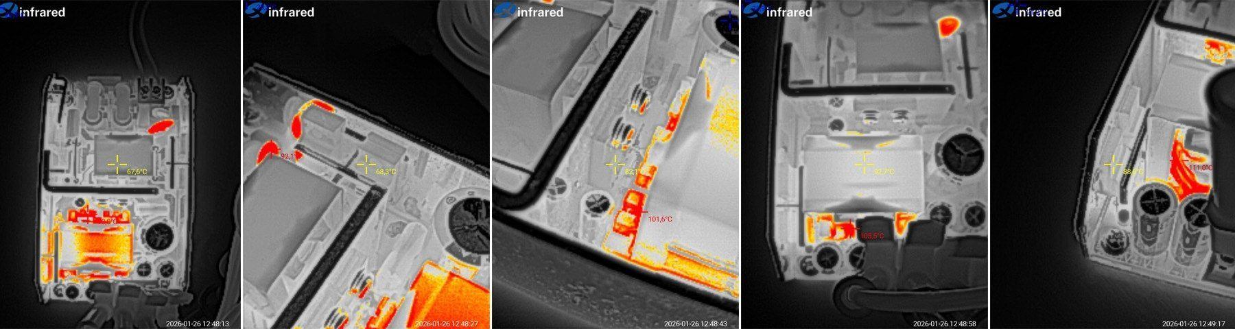
Temperatures of the key components at 6.6 and 10 A.
At 6.6 A, the PFC inductor was at 52.5°C, the PFC transistors at 54°C, the power supply transistors at 60°C, the transformer at 75°C, and the output diodes at 66.4°C. Excellent, in my opinion.
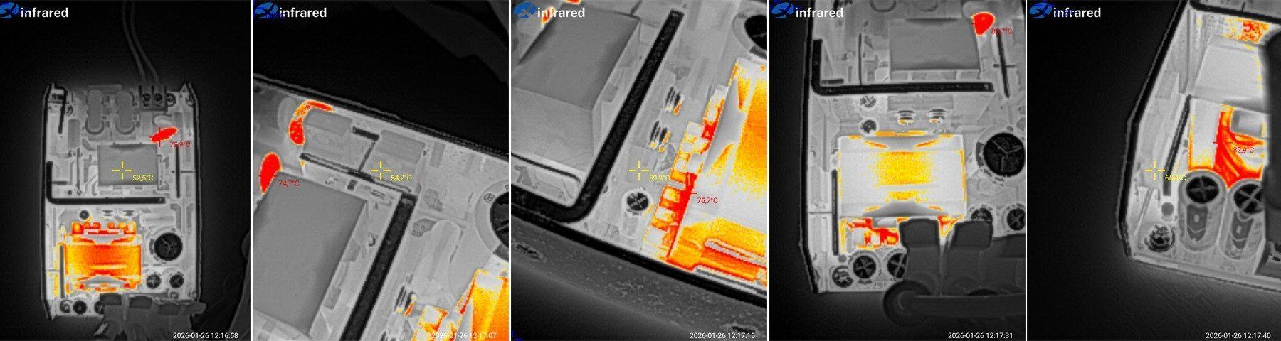
At 10 A, things had of course changed, but I wouldn’t say the unit was overheating.
The PFC inductor was at 67.6°C, the PFC transistors at 68°C, the power supply transistors at 82°C, the transformer at 93°C, and the output diodes at 89°C.
By the way, judging by the temperatures of the PFC transistor and inductor, the PFC is indeed running at 6.6 A. So the changes in efficiency and ripple must be due to something else—more specifically, a change in operating mode and frequency. You can actually see this in the oscilloscope captures.
I do have one concern about the temperatures: the transformer winding is above 100°C, which is quite high. It’s entirely possible that if the power supply had run longer, the transformer would have gotten even hotter. So, in my subjective opinion, I wouldn’t run it at 10 A for extended periods unless you provide at least some airflow.
The overload protection kept bothering me, especially since the power supply itself is interesting. In the end, I took it apart again, desoldered the shunt, and measured it at about 35 mΩ.
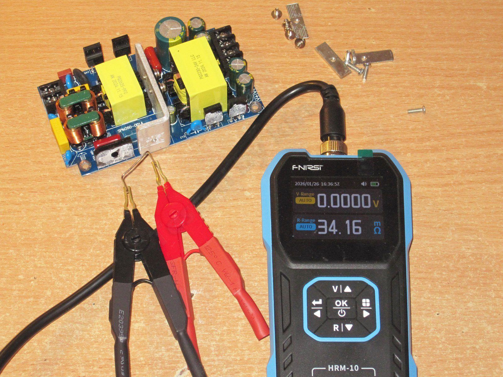
Then I figured that if the protection doesn’t trip at 15–16 A, I could safely increase the shunt resistance by about half.
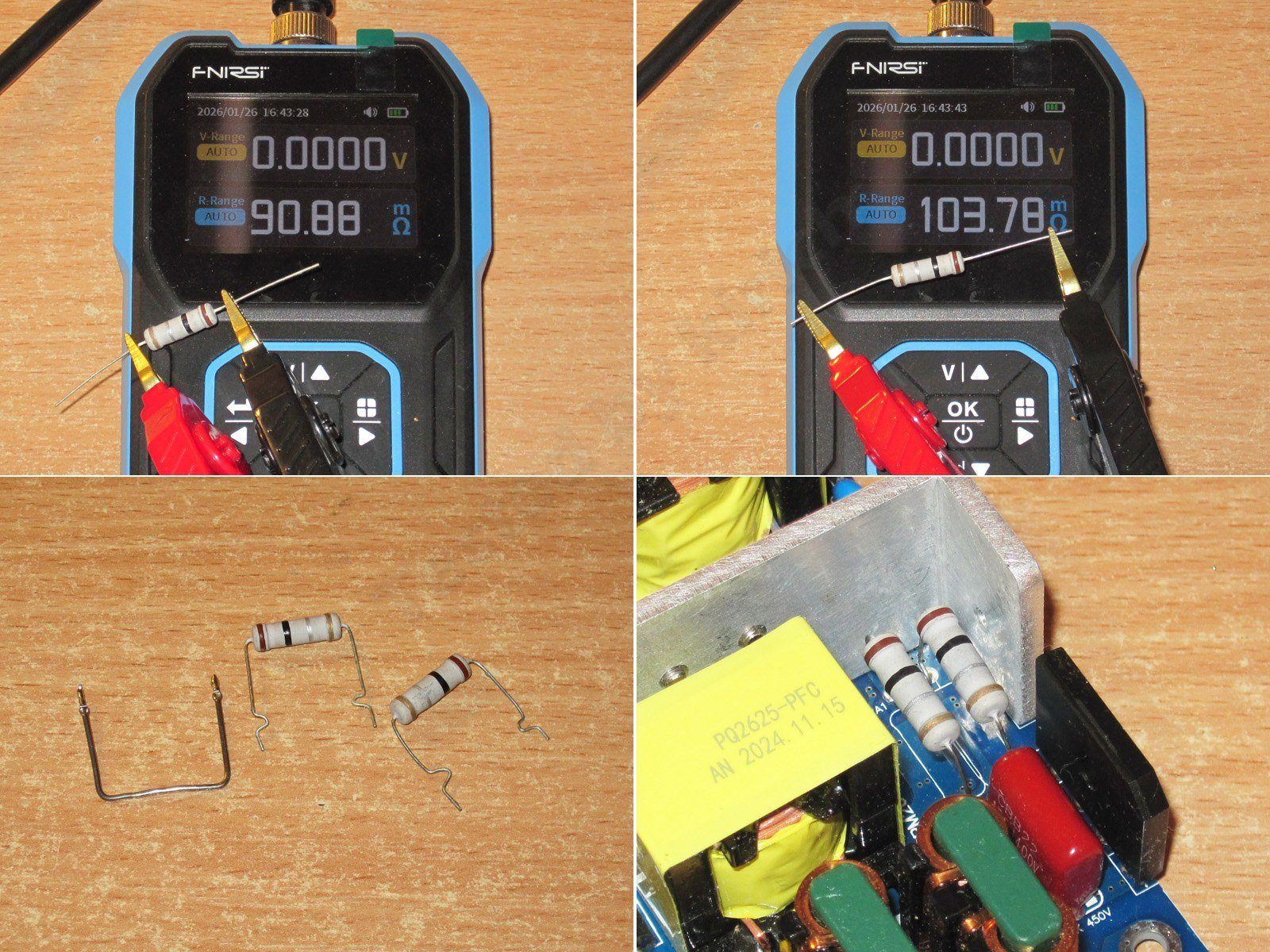
I got some 0.1 Ω resistors and planned to put two in parallel, but first I have to show how much the resistor leads can affect the measurement when the resistor itself has such a low resistance.
Measuring closer to the body gives 91 mΩ; closer to the end, it’s almost 104 mΩ.
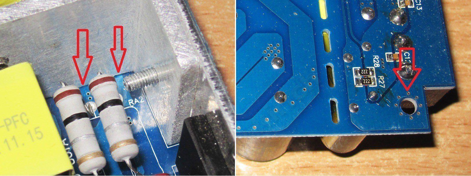
In the end, I had to shape the leads so they’d be used almost all the way along. I soldered the pair in that configuration. The calculated resistance should be exactly 50 mΩ, almost one and a half times the original shunt’s 34 mΩ.
I wasn’t too happy with this arrangement, though. The resistors sit high, their leads are thin, and there’s a heatsink and its mounting screw nearby. I’d need a shorter screw and some insulation—or to secure the resistors somehow so they can’t short against the heatsink if the unit gets knocked. The heatsink is connected to the power supply’s case.
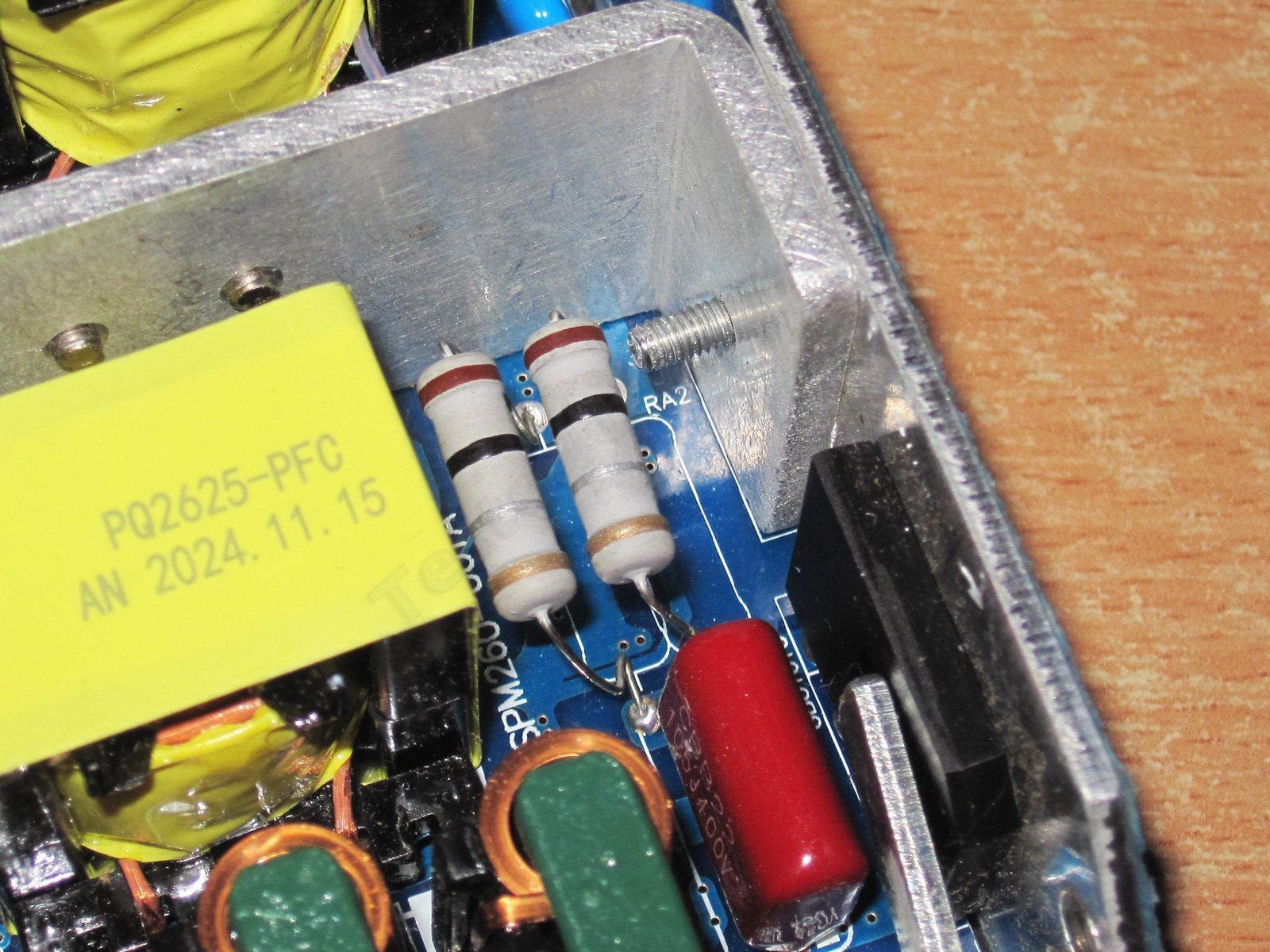
Speaking of the heatsink and safety: the photo shows the high-voltage-side traces running directly underneath it. As I mentioned, the heatsink itself is connected to the case, which in turn is directly connected to the output negative terminal.
This is one of those cases where they tried to do everything right, then ruined it all with one blunder at the end. I only noticed it while writing the review.
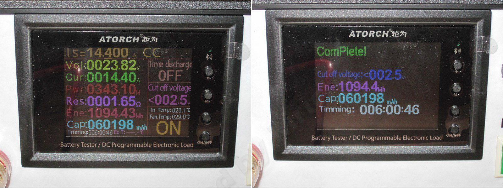
So, what about the current? It’s certainly better now, but still nowhere near what I’d call “good.” Even with a 50 mΩ shunt, the protection trips at around 14.3–14.4 A. By my estimate, with the original shunt it would trip at... about 20 A! Yikes...
Anyway, I’ve ordered resistors for a new shunt. I want to get 60 mΩ, which should bring the trip current down to around 12–12.5 A. At first I was thinking of using a pair of 120 mΩ resistors, but then I went with 180 mΩ resistors. I want to keep three of them so the shunt can handle more power, just in case. As for the heatsink, it looks like I’ll have to think about adding some insulation.
Conclusions.
This power supply is quite a mixed bag. On the one hand, it’s assembled very neatly, with a good input filter, active power factor correction, an LLC topology, and low ripple. But it also has some nearly fatal flaws.
There are essentially two flaws: first, the protection is set to a whopping 20 A; second, the heatsink almost touches the high-voltage traces and is directly connected to the output. The first is easy to fix by replacing the stock shunt with a 50–60 mΩ one. The second, though, will take some work, that’s for sure...
I almost forgot to mention the efficiency. It’s fairly good, although I think it could be noticeably better if the manufacturer had spent a little more and fitted a synchronous rectifier on the output. I’ll probably show you a 12 V, 200 W power supply soon that has no heatsinks at all, thanks in part to its synchronous rectifier.
That’s all for today. I’ve told you everything I could, and I hope it helps you make the right choice—or, if you’ve already chosen one, improve the unit you have.
$23.01
This page was found when searching for:
обзор блока питания kirich, 8, плата lt-96130v1.1
обзор блока питания kirich, 8, плата lt-96130v1.1
The figures from this review are in the measurement database: Power supplies
Calculate manuallyAll calculators
Discounted products
You may be interested in



Discounted products
Support the project
All the content on the site and the advice are free, but we’d be grateful for your support of the project and the channel!
Comments7
Discuss on the forumHave a question or some experience to share? Discuss the article with the author and readers: the forum is a convenient place to share schematics and photos.
Go to the forumOnly registered readers can comment. It takes a minute to sign up, and you can log in with the same account you use on the forum.
Log inRegister
Comments are published in their original language.