
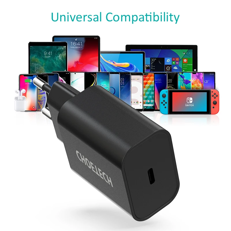
Choetech QC 18W power supply (charger) bought on sale
$6.93 (куплено за $2.54)
I’ll try to keep this short and to the point, so there won’t be too much text or too many photos, but as always, all the tests will be here :)
There were two deals: one offered the power supply (charger) on its own or with a cable, and the other offered various cable options.
I ordered the charger with a Type-C cable, plus a separate microUSB cable. The total came to $2.54 for the power supply and cable, and $0.16 for the 0.5 m microUSB cable.
I received everything in one package, even though I placed two orders. I don’t really mind—in fact, it’s even better. It arrived pretty quickly, too: about two weeks after I placed the order. Everything was packed in separate zip-lock bags with branded printing.

I’ll start with the cables.
One cable is 1 m long and came with the charger; the other is 0.5 m long and was ordered separately.

1, 2. The 1-meter cable has a Type-C connector; the other has the more common microUSB connector.
3, 4. The cables are actually about 7–8 cm longer than stated. I deliberately chose a short microUSB cable: it was cheaper, and I didn’t need a long one.
5. The Type-C cable has a standard-length plug, so be careful. The cable on the left, for example, came with my smartphone, and its plug is longer than the standard.
6. The longer cable (Type-C) also has a larger outer diameter—it’s clearly thicker, although I didn’t measure it. It also holds its shape a little when bent, unlike the thinner one.

Probably the most important cable parameter is its resistance—or, equivalently, the voltage drop across it when connected to a load. For the test, I grabbed the first power supply I could find, along with a USB tester and an electronic load.

I ran two tests: the tester’s built-in resistance measurement and a simple voltage-drop test.
1. Resistance measurement: first, run the tester’s automatic zero calibration. To do this, connect it to the power supply output; at the set load current, it treats the output voltage as a reference zero.
2, 3. Then connect the cables under test. Based on the voltage drop, the tester calculates the cable resistance, including the contact resistance of the connectors. I got 0.14 Ω for the Type-C cable and 0.15 Ω for the microUSB cable, even though it’s half as long—the conductor cross-section makes a difference.
4. The second test was just for good measure. I connected the tester to the power supply; at 2 A, the voltage was 5.11 V.
5, 6. I measured the voltage after each cable in turn at the same current. It was 4.83 V for the first cable (a 0.28 V drop) and 4.80 V for the second (a 0.31 V drop).
So, to get at least 4.75 V at 2 A, the voltage before the cable needs to be at least 5.03 V in the first case and 5.06 V in the second. In other words, these cables are usable, but it’s best to use a charger with an output voltage slightly above the standard 5.00 V.

And now for the main event—the reason for this whole post.
The power supply (charger) came with an instruction manual and some sort of slip of paper. The manual also lists the technical specifications:
Model: Q5003
Input: AC 100–240 V, 50/60 Hz, max. 0.5 A
Output: DC 3.6–6 V 3 A, 6–9 V 2 A, 9–12 V 1.5 A
Maximum output power: 18 W.

1. The case is matte, which is a welcome change from the current obsession with glossy finishes.
2. The same specifications are printed on the power supply case.
3. The AC plug pins are straight, although they’re supposed to angle slightly toward the center.
4. There’s one USB port, in bright orange.

The case is slightly larger than the other power supplies I already have. I’ve already reviewed the one in the middle. The one on the far right was also bought in a sale, but a long time ago, and I still haven’t gotten around to testing it.

My two previous power supplies look similar to each other, and are therefore different from the one under review.
1. The connector is in a different position.
2. The older units have identical specifications, but are rated for 1.6 A at 12 V, compared with 1.5 A for the one under review.

First, let’s check support for the various fast-charging modes.
1, 2. I tried two different testers. The results are similar, but the larger tester shows support for Samsung AFC 12V.
3, 4. In QC 3.0 mode, the voltage can be adjusted from 3.64 to 11.94 V, which is slightly below the stated range (3.6–12 V).

Next, we connect the load and move on to the load tests.
The first test was conducted at 5 V without a USB tester. The rest were done through the tester, which introduced additional measurement error because it has a shunt and an extra connector inside.

The first test was an efficiency measurement. The accuracy here is not very high, of course, since the wattmeter itself has a fairly large error, especially at low power levels.
I’m not including the results for the 12 V 1.5 A mode, since they are identical to those for the 9 V 2 A mode.

Load test.
5 V output: the power supply went into protection at 3.9 A, with a perfectly acceptable 4.93 V at the output.

QC 9 V: protection kicked in at 2.4 A, with 8.85 V at the output. The graphs on the left show the voltage measured with no load or at low current, to assess the voltage drop.

The remaining graphs are under the spoiler.


Output ripple assessment.
The test was run in four modes: with no load and at the maximum rated current for 5, 9, and 12 V.
With no load, the power supply switches to “green” mode, so the pulse repetition frequency is very low, and consequently the power drawn from the mains is also low.
Under load, ripple is around 120–150 mV, depending on the output voltage, which is perfectly normal. Interestingly, the ripple pattern is very similar to the results of the test of this charger.

Of course, I took the power supply apart. I wouldn't say it was easy to disassemble, but not being able to take it apart at all would have been pretty bad.

At first, I thought the transformer was thermally coupled to the case with silicone sealant, but it turned out that wasn't quite the case. More on that later.

The thermal test didn't go quite as usual. I initially planned to test at 5, 9, and 12 V, but after the run at 5 V I accidentally cleared the graph data, so I ended up running the tests in the order 9, 12, and 5 V.
In total, the test lasted 1 hour 20 minutes at maximum power, in the 5, 9, 12, and 5 V modes. The last three stages are shown on the graph.

I measured the case temperature, since measuring it without the case would be pointless, and doing it any other way is simply very difficult.
Here are the results:
1, 2, 3. Output voltage: 9 V, current: 2 A. Top of the power supply after 10 minutes from the start of the test (30 minutes total); top and bottom after 20 minutes (40 minutes total).
4, 5, 6. Output voltage: 12 V, current: 1.5 A. Top of the power supply after 10 minutes from the start of the test (50 minutes total); top and bottom after 20 minutes (60 minutes total).
7, 8, 9. Output voltage: 5 V, current: 3 A. Top of the power supply after 10 minutes from the start of the test (70 minutes total); top and bottom after 20 minutes (80 minutes total).
The power supply case warmed up to about 56–58 °C, and the temperature didn't change after that, regardless of the load or how long it had been heating up.

After a test lasting almost an hour and a half, I practically yanked the power supply plug out of the wall and measured the temperature of the internals, trying to do it as quickly as possible. Photos from two angles.
According to the thermal camera, the maximum internal temperature was 81 °C. I couldn't get to the PWM controller or the output rectifier, of course, so this is most likely the transformer temperature.

Once I removed the board, it turned out that the transformer wasn't glued to the case, as I'd initially thought. Though if it had been, heat dissipation would have been a little better.
I liked the overall build quality. Of course, I would have liked at least an output filter and “better” capacitors, but I guess I'm asking too much for the price. Still, they did fit a proper fuse, which is nice.

1. The input has two 15 µF, 400 V capacitors, so everything is great here.
2. The CX7509 PWM controller has a built-in 650 V transistor, according to the datasheet, and is designed for switching power supplies rated up to 18 W.
3. Surprisingly, the output uses an LN5S21 synchronous rectifier, which is definitely good news. I think this made a significant contribution to reducing heat; the charger shown above just had a diode. The datasheet says it's used in power supplies with 5/9/12/20 V outputs and contains a MOSFET with an on-resistance of 15 mΩ and a maximum voltage of 105 V. But there's a downside: according to the same datasheet, its maximum continuous current is 2.4 A at 5 V and 2.5 A at 12 V, so the stated 3 A is a bit... optimistic, though it works.
4. The output has a pair of 680 µF, 16 V capacitors. The capacitance is fine, but 25 V capacitors would have been much more reassuring.

To wrap things up, I decided to run one more test—or rather, an experiment—to check the voltage drop under load, excluding the drop across the USB connector.
To do that, I connected directly to the board.

Across a load range of 0–3.9 A, the voltage dropped from 5.01 to 4.99 V.

I figured that exactly 5 V is great, of course, but a little low, so I made a small adjustment: I cut the feedback trace and added a 3.4 kΩ resistor. With no load, I got:
Instead of 5 V: 5.145
Instead of 9 V: 9.235
Instead of 12 V: 12.32
The voltage will drop a little under load, of course, but that's fine by me. I could leave it as is, but since I'd already taken it apart, why not fix this while I was at it?

And that's about it.
In short, it has its advantages and disadvantages. It handles the load well and doesn’t get very hot, but there’s no compensation for voltage drop in the cable, and according to the documentation, the output rectifier is rated for 2.4–2.5 A, not the claimed 3 A.
On the other hand, the charger cost me $2.50, including a 1-meter cable, and I think it’s worth every penny. It supports QC, looks very neat, and works reliably.
Overall, I liked it. That’s all for today; I hope you found this useful.
$6.93 (куплено за $2.54)
This page was found when searching for:
qc18w плата, управление синхронным выпрямителем
qc18w плата, управление синхронным выпрямителем
The figures from this review are in the measurement database: Chargers
Calculate manuallyAll calculators
Discounted products
You may be interested in


Discounted products
Support the project
All the content on the site and the advice are free, but we’d be grateful for your support of the project and the channel!
Comments9
Discuss on the forumHave a question or some experience to share? Discuss the article with the author and readers: the forum is a convenient place to share schematics and photos.
Go to the forumOnly registered readers can comment. It takes a minute to sign up, and you can log in with the same account you use on the forum.
Log inRegister
Comments are published in their original language.