
LRC-60-1050 and LRC-60-1400 power supplies (drivers) for LEDs up to 60 W
₴375 (около $13.6)
To start with, these devices are often called power supplies. That’s more or less what they are, but I think it’s more accurate to call them drivers: their job is to regulate current, while they only limit the voltage to a level that’s safe for the driver itself.
The link in the title goes to one of the models shown here. I’ll also cover a higher-current, lower-power model, the LRC-60-1400.
You can buy them from at least two places:
For UAH 425 at Rozetka — LRC-60-1050, LRC-60-1400
For UAH 375 at Radiomag — LRC-60-1050, LRC-60-1400
The price doesn’t depend on the output current; it’s determined only by the power rating and the seller’s “appetite.” I hope Light Route will start selling its products directly to retail customers in the future, which should mean even better prices.
So, let’s get started.
They look exactly like the power supplies from the previous review, with the same dimensions (130 × 40 × 30 mm) and the same wire length (150–170 mm).
By the way, I think the manufacturer should find a way to distinguish the power supplies from the drivers. They have similar model numbers but serve different functions, which could confuse an inexperienced buyer.

The only differences are the model numbers and the listed specifications.

Drivers in this power range are available in six current/voltage combinations: the higher the current, the lower the voltage the driver is rated for. This review covers the 1050 mA and 1400 mA versions.
Unfortunately, the manual is only available in Ukrainian. But we’re used to dealing not just with English, but sometimes Chinese too—and at least numbers don’t need translating.

As with the power supplies, the input wires are white, while the output wires are color-coded for polarity. Last time, someone asked about the wire gauge. It was awkward to measure, but for comparison, the wire on the right in the photo is 0.5 mm² and the one on the left is 1.5 mm², so the original wires are at least 0.75 mm².

The drivers are rated IP66. This is achieved by filling the interior with a rubber-like compound. As with the power supplies, there’s a removable cover on the bottom.

Thanks to one of my regular readers, I have several drivers made by Mean Well, so I can at least compare their dimensions, since not all of them work.
From top to bottom, the drivers are rated at 75–80 W (depending on the supply voltage), 80 W, 25 W, and 56 W, respectively.

The 25 W driver looks the most similar. A direct comparison isn’t possible because the power ratings are so different, but I’ll show a few tests anyway. Also, this Mean Well model isn’t waterproof; open the case and all the components are immediately visible.

To avoid confusion, each test will start with the lower-current driver (1050 mA), followed by the higher-current one (1400 mA).
I’ll start by measuring the output current and power consumption with no load, although this isn’t a normal operating condition. Since there’s a large capacitor on the output, power should only be switched on the input side. Don’t disconnect the output while the driver is running, or you could damage the LED module.
Both drivers’ output voltage fluctuates slightly, which also affects their power consumption, causing it to vary from 0.2 to 0.4 W.
The maximum voltage for the LRC-60-1050 is shown on the left, and for the LRC-60-1400 on the right.

Here’s what the process looks like in real time.

As I wrote above, unlike ordinary power supplies, LED drivers are designed to operate in constant-current mode. This is because LEDs and modules based on them limit the voltage themselves to the required level.
For the test, I used an electronic load capable of operating in CV (Constant Voltage) mode. I already explained this feature in my review of a charger. In short, power supplies (voltage sources) are tested in current-limit mode, while chargers and drivers (current sources) are tested in voltage-limit mode.
The first driver delivers an output current of 1025–1045 mA, regulating it over a voltage range of 27.2–57.5 V.

Next, I checked the efficiency. The test was performed at five points: the rated minimum, middle, and maximum voltages, plus the absolute minimum and maximum (outside the operating range).
I also measured the power factor, which is about 0.99 across the full load range.

The second driver has a slightly wider range and regulates the current at voltages from 19.5 to 48.2 V, compared with its specified operating range of 25–40 V.

The claimed efficiency is up to 92%. Since my wattmeter reads a little high at low power, the 60-1050 should come close to that at the top of its range, while the 60-1400 falls short by a couple of percentage points.

I monitored the output voltage using the electronic load's readings, then double-checked it with a second multimeter just to be sure. The readings match.

Thermal performance.
The power supply was simply placed on the table, with the room temperature at 26–27 °C.
I also monitored current drift as the unit warmed up during this test.

After an hour of operation at the maximum specified voltage, the current hadn't changed at all, so I set the highest possible voltage and continued the test for another 15 minutes. After that, the current dropped, but by just 5 mA.

1. Temperature after a one-hour test at 100% load
2, 3. Another 15 minutes in overload, above and below the rated range, with the cover on.
At the rated maximum operating point, I got 54 °C, or a 30 °C temperature rise. The specified temperature rise is 50 °C, and the maximum absolute temperature is 80 °C, so there's still about 20–24 °C of headroom. That means it should handle an ambient temperature of 50 °C without overheating, which is perfectly reasonable.

I tested the 60-1400 model in the same way: one hour at the maximum specified voltage, followed by another 15 minutes at the limit.

Out of curiosity, I took a thermal image at the start of the warm-up. You can see where it gets hottest.

Interestingly, the datasheet specifies not only the dimensions and wire assignments, but also the point of maximum temperature. That's pretty much where it turned out to be.

The temperature here is about 4 °C higher, due to the lower efficiency. For this power supply, the maximum calculated ambient temperature is about 45 °C.

Measuring voltage and current ripple.
I used a high-power 10S10P LED array as the load, with an operating voltage of about 30–35 V, which suits both drivers. I also used resistive loads of 30 and 20 Ω, respectively, to match the drivers' specifications.

To measure current ripple, I connected a 1 Ω resistor in series with the negative lead and hooked up the oscilloscope across it. This test may not be entirely correct, although it seems perfectly reasonable to me.

I measured two types of ripple: at 100 Hz and at the switching frequency.
1, 2. Current ripple, LED module load.
3, 4. Voltage ripple, LED module load.
5, 6. Voltage ripple, 30 Ω resistor load.
Although the specified current ripple is 10%, the actual peak-to-peak ripple at 100 Hz turned out to be five times higher. That is, at a current of 1 A, the ripple should have been 100 mV, but I measured 500 mV.
Voltage ripple is included as a supplementary measurement, since it isn't critical in this case. However, I should note that the power supply stubbornly refused to start with a resistive load, tripping its protection. I could only get it to start in this order:
Start it with the LED module
Connect a resistor in parallel
Disconnect the LED module.
Also, high-frequency voltage ripple is only 60-80 mV, depending on the load, which is very good at this voltage.

The second module has a larger current ripple, but the current here is 1.4 A versus 1.05 A for the previous one, so the ripple is lower as a percentage.
Overall, though, the results are very similar. The only difference is that this power supply started without any trouble with a resistive load (20 Ω).

This gave me pause, so I decided to see how a Mean Well would perform in the same tests. I connected the same module as a load and measured its current and voltage ripple.
The test showed that its results were even worse. The previous units had 500 mV at 1.05 A and about 600 mV at 1.4 A, while this one had 600 mV at just 0.7 A. In other words, its ripple is twice as high as that of the 60-1400 version.
But Mean Well played it clever: they don't specify this parameter at all.

A little later, I wondered whether there might be an error in the test method or some interference, so I repeated the test with a DS203 oscilloscope in DC mode. The oscilloscope itself wasn't connected to the mains, either.
The results were exactly the same: at a frequency of 100 Hz, the current varies from 0.75 to 1.25 A, with an average of about 1 A.

Another important point is how long the power supply takes to reach its operating mode. The specs say less than one second.
The test showed that after being left off for a long time, it takes 2 seconds to start. Subsequent starts are much faster, at around 1-1.2 seconds.
The long startup time is a bit of a mixed bag. It's fine for an auxiliary light at home (say, in a closet) or an outdoor light, but if it's the main room lighting, it'll definitely get annoying—even if it takes just 0.5 seconds to turn on. I've tested this.

For comparison, the Mean Well starts almost instantly. I suspect that's because it has less output capacitance, which would also explain its higher current ripple.

Operating voltage range.
The minimum specified voltage is 175 V, but testing showed that the driver shuts down at around 140 V. This could be useful in the event of brief voltage dips, but I wouldn't recommend running it at these voltages for extended periods.
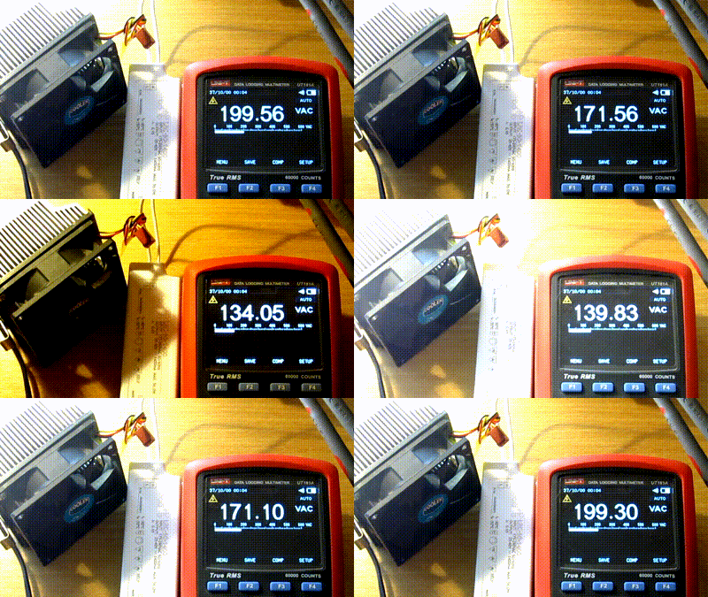
But operation at elevated voltage is much more interesting. This power supply has a claimed “killer feature”—more precisely, protection against high input voltage.
To paraphrase the text below, the power supply can withstand an input voltage of 380 V for 24 hours, disconnecting the load in the process. Once the voltage returns to the normal operating range, it automatically reconnects the load.

For household use, especially if there's a voltage relay at the entrance to your house or apartment, you'll probably never need this kind of protection. But it can be a big help when installing drivers for outdoor lights.
Outdoor lights are often powered from wires strung between poles. In an emergency—strong winds, falling branches, careless electricians—those wires can cross. In that case, there's a fairly high chance that the full line voltage will reach the light's input. Something similar can happen if the wiring is mixed up and two live wires are connected instead of live and neutral.
I've touched on this topic before in my article about varistors, and I can say it's still relevant today.
But let's get back to our test subjects.
If the problems described above occur, your equipment may see something like this at its input instead of the usual 220/230 V—not a pretty sight.
By the way, a small request for the developers: the specs say 380 V for 24 hours, but I should point out that our country has already adopted 230/400 V, not 220/380 V.

The LRC-40-xxx and LRC-60-xxx series drivers are specified to have protection against these conditions, and I was very interested to test it. I used a variac, connected a boost transformer to it, and started experimenting.
You can see that when the voltage exceeds the critical level, the driver disconnects the load and reconnects it once the voltage drops.
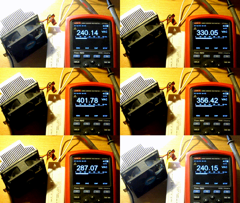
During testing, I found a discrepancy with the specs. They say the driver shuts down at 300 V and turns back on at 290 V or below, i.e. There is a small amount of protective hysteresis.
In my tests, shutdown occurred at around 307–308, and it switched back on at 310. The voltage spikes after shutdown are caused by the driver being switched through a transformer, but they don't affect the trip threshold, since the voltage changes only after the thresholds have been reached.
So there's a chance it could get stuck in a "blinking" state if the voltage is close to the threshold. The chance is low, of course, and it's unlikely to do the driver any harm, but I would still add some hysteresis.

But I didn't stop there and decided to test it for longer. Keeping it running for a full day wasn't very convenient, so I settled on an hour, although the test actually ended up lasting almost an hour and a half in total.
So, I took the power supply and applied about 415 V to the input—that is, 400 V line voltage under the new standard, plus a little headroom.
Over the course of an hour, the voltage fluctuated between 404 and 419 V, averaging about 414 V.

After that, I measured the temperature. At the hottest spot—which was practically the only one—it was 42 degrees.

Then I brought the voltage back to normal, and the driver worked as if nothing had happened.

During the tests with increasing and decreasing the voltage, an "undocumented feature" showed up: a brief change in operating mode, noticeable as the LED flickering.
As the voltage passes through the 275–280 V range, the LED briefly flickers. You could call this a drawback, if it weren't for one thing: since it happens at a fairly high voltage, the flicker can alert you that something is wrong with the mains and it's time to get the electricians on the case.

As is customary in my reviews, I took the power supply apart. First, carefully cut around the perimeter, then pull out the block containing the electronics by its wires. The potting is excellent here.

After about an hour of work with tweezers, followed by a toothpick, I ended up with a pile of potting compound and a relatively clean board. Unfortunately, it's quite difficult to remove it all completely, so I left it as is.

The manufacturer's website shows photos of three models. Since they make three power ratings—25, 40, and 60 W—the middle one should be the most powerful, and that's the one I expected to find inside.

But the board turned out to be noticeably different, both in its layout and in its circuitry. I think the changes are related to the addition of overvoltage protection, meaning this is already the second generation of drivers.
Unlike the one shown in the photo, this layout is more compact and also neater.

There's a video on the website, and it also shows the old board version (visible from 1:38). I think it's time for the manufacturer to update the photos on the product page, especially since I like this version better.
For a few reasons, I won't be digging into the circuitry or reverse-engineering it today. I'll just say that the module consists of two boards: the main board and a submodule with the PWM controller and its supporting components. The main filter capacitor is on the secondary side. The circuit itself also resembles the block diagram shown in the original description.
A 0.22 µF, 630 V capacitor is installed between the submodule and the transformer. In this case, it acts as a filter capacitor, so the power supply's maximum continuous voltage is limited to around 440–445 V.

1. The input has a full-fledged filter consisting of two inductors and two X capacitors.
2. The input has a 1 A fuse and a 680 V varistor. Judging by the thermal image, it was the varistor that heated up at the elevated voltage.
3. A pair of 10 µF, 400 V capacitors connected in series.
4. An interwinding Y capacitor, installed in a somewhat odd position, even though there are more convenient holes for it. I assume that if it had been mounted along the board, it would have stuck out past the edge (Y capacitors are often bulky), so they soldered it into a different hole.
5. The output uses an SFF1605CT diode assembly rated for 300 V and 16 A, which is rather overkill for an output current of 1 A. Like the high-voltage transistor, it's mounted on the heatsink with double-sided tape.
6. The output filter capacitor is 2200 µF, 63 V. I think this partly explains the slow startup.

There are only a few passive components on the underside, including the snubber components.

Now that the tests are complete, we can draw some conclusions, and they apply to both power supplies.
I'll start with the good news.
The driver works well, providing excellent current regulation not only within its specified output voltage range, but beyond it as well. I also have no complaints about the temperature, and it gets extra points for being able to withstand high input voltage for extended periods.
The build quality is good, and everything inside is neat, even though the case is potted with compound and nobody will see what's inside—except, perhaps, the really curious.
There is, however, a "fly in the ointment."
The drivers don't meet the specified startup time of less than one second when starting from cold, which puts them in the "non-residential" category. So if you install one in a streetlight, garage or storage-room lighting, and so on, it'll work great. But if, say, you use it to power the lights in an entryway, the long delay before they turn on will be very annoying.
As for the ripple, it's not visible to the eye or on video. Mean Well has twice as much ripple and doesn't seem concerned at all.
During testing, I noticed an "idiosyncrasy": a brief flicker as the voltage passes through the 275–280 V range. But as I wrote, this is both a good and a bad thing, depending on how you look at it.
In short, these are perfectly good replacements for budget Mean Well units. They also have protection against the kind of problems we see in our power grid, such as a broken neutral or crossed wires on utility poles, as well as moisture protection.
That's all from me. I hope you found this useful, and as always, I'm happy to answer any questions.
₴375 (около $13.6)
This page was found when searching for:
1, https://www.kirich.blog/obzory/bloki-pitaniya/911-bloki-pitaniya-drayvery-lrc-60-1050-i-lrc-60-1400-dlya-svetodiodov-moschnostyu-do-60vt, форум ремонт светодиодного блока питания ипс60-1050тд на микросхеме 28810, форум ремонт светодиодного блока питания ипс60-1050тд, ипс60-1050тд чем можно заминить, ипс 60-1050т схема принципиальная, форум ремонт светодиодного драйвера ипс60-1050тд, блок питания lcr-60-140, форум ремонт светодиодного драйвера ИПС60-1050ТД(750-1050), как разобрать блок питания залитый компаундом, ипс100 1050т ip67 1300 электрическая схема, замена ипс60 1050т в светильнике, замена ипс60-1050т в светильнике, trion star 60 1050t industrial, ипс60 1050тд 750 1050 ip20 0105 найти аналог, lpc 60 1050, источник питания ипс60 1050тд 750 1050 0105 аналоги, ипс 60 1050тд 750 1050 ip20 как регулировать напряжение, ипс60 1050тд схема встраивания, ипс 60 1050т аналог, lpc 60 1400 схема, lpc 60_1050 схема, ипс 60 700т схема ремонта, драйвер тип ипс60 1050тд, tridonic lc 60w 1050/1200/1400 ma flexc sr adv схема подключения
1, https://www.kirich.blog/obzory/bloki-pitaniya/911-bloki-pitaniya-drayvery-lrc-60-1050-i-lrc-60-1400-dlya-svetodiodov-moschnostyu-do-60vt, форум ремонт светодиодного блока питания ипс60-1050тд на микросхеме 28810, форум ремонт светодиодного блока питания ипс60-1050тд, ипс60-1050тд чем можно заминить, ипс 60-1050т схема принципиальная, форум ремонт светодиодного драйвера ипс60-1050тд, блок питания lcr-60-140, форум ремонт светодиодного драйвера ИПС60-1050ТД(750-1050), как разобрать блок питания залитый компаундом, ипс100 1050т ip67 1300 электрическая схема, замена ипс60 1050т в светильнике, замена ипс60-1050т в светильнике, trion star 60 1050t industrial, ипс60 1050тд 750 1050 ip20 0105 найти аналог, lpc 60 1050, источник питания ипс60 1050тд 750 1050 0105 аналоги, ипс 60 1050тд 750 1050 ip20 как регулировать напряжение, ипс60 1050тд схема встраивания, ипс 60 1050т аналог, lpc 60 1400 схема, lpc 60_1050 схема, ипс 60 700т схема ремонта, драйвер тип ипс60 1050тд, tridonic lc 60w 1050/1200/1400 ma flexc sr adv схема подключения
The figures from this review are in the measurement database: Power supplies
Calculate manuallyAll calculators
Discounted products
You may be interested in


Discounted products
Support the project
All the content on the site and the advice are free, but we’d be grateful for your support of the project and the channel!
Comments21
Discuss on the forumHave a question or some experience to share? Discuss the article with the author and readers: the forum is a convenient place to share schematics and photos.
Go to the forumOnly registered readers can comment. It takes a minute to sign up, and you can log in with the same account you use on the forum.
Log inRegister
Comments are published in their original language.