
Electronic Load CL24: What Are You?
$40.91
As a reminder, if you want to keep up with new posts on the blog, I recommend following me on Instagram. I'll post notifications about new articles there, and maybe write about something interesting too: link to my account
You can also subscribe to updates and new articles on the Telegram channel - https://t.me/KirichBlog
It took me a long time to find time for this review. First the load took ages to arrive, then there were holidays, then I got swamped with work. And just recently, when I was finally about to sit down and write it, we spent two days without power, "thanks" to the Rashists. Most of the material had actually been prepared a while ago, but I finally decided to write it up. I may have missed something here or there, but since this load is essentially just an updated version of its predecessors, some tests and descriptions can be shortened. Repeating the same thing for the fifth or sixth time would be pretty silly. So if anything is unclear or you'd like to know more, just ask in the comments.
I ordered two units at once, not just because I wanted two, but first, because the new version has a feature related to using two units, and second, because the store offered a review discount, but the discount on a single unit was tiny. So I figured that since you use my reviews to improve your products, it would be nice to get something in return, and persuaded them to give me a discount on two units.
Some time later, I received the familiar box, containing two plastic trays, each with a load inside.

One thing to note: the store offers four package options, as I mentioned in the announcement. I received both units with the top-tier package.
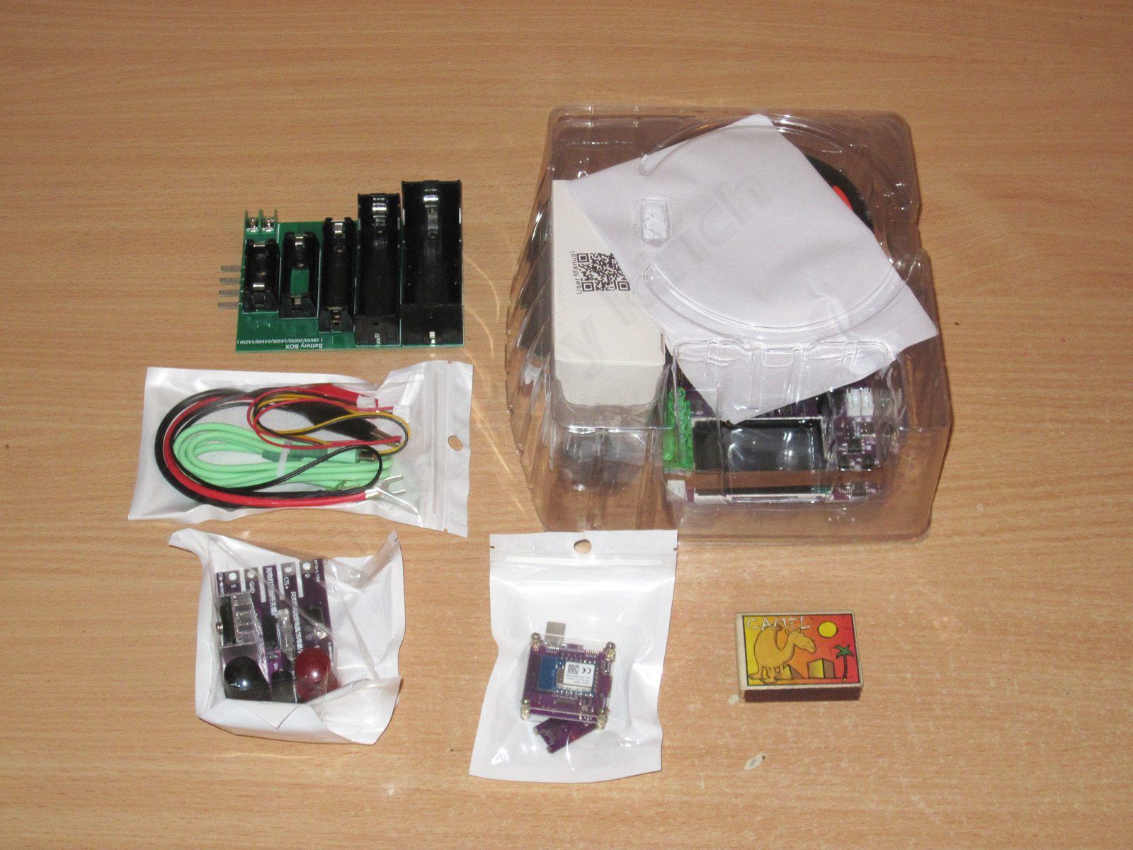
So, besides the load itself, the top-tier package includes:
First, the items included with many of their loads:
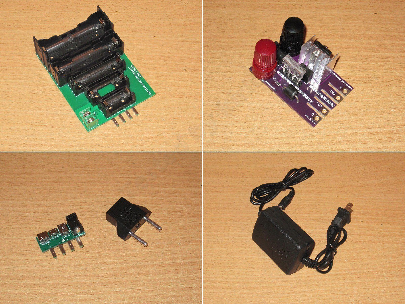
1. Battery holder
2. Charger switching board. I've mentioned before that I ended up designing my own, which is safe for the charger because it completely disconnects the circuit and also has a proper reverse-polarity protection circuit. The original board doesn't really protect against this. I also significantly reduced the voltage drop, so you can charge at 20–30 A without any problems, or even 40 A with additional cooling.
3. Adapter for testing USB chargers and a power supply adapter.
4. Power supply, the same as with the other loads, except the 24EW comes with a more powerful one.
Update: while checking the charging function, I noticed that the developers had revised this board. Current no longer flows toward the charger, thanks to the addition of a diode. Honestly, they would have been better off leaving it alone: in solving one problem, they introduced several new ones, including:
1. The current is limited by the diode's rating, so the maximum is 4–5 A.
2. There was already a fairly large voltage drop across the transistor, which significantly slowed down charging low-voltage batteries. Now there's an additional drop to take into account.
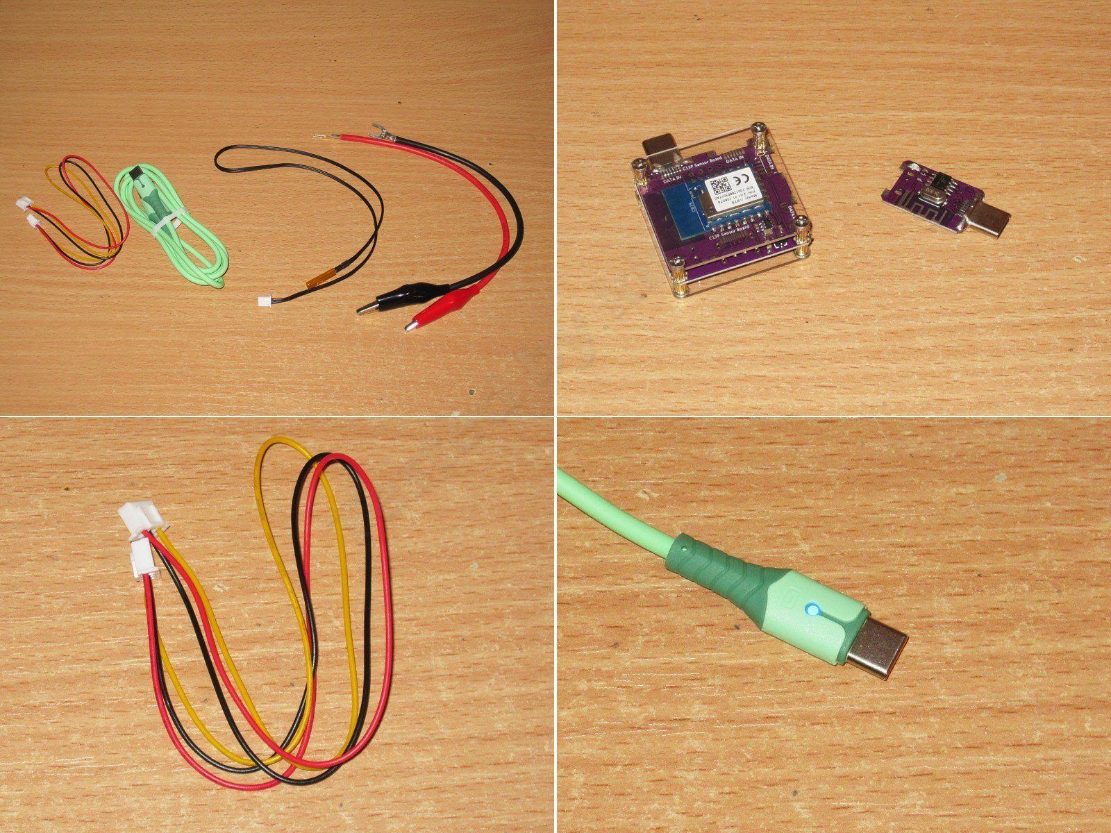
And here's something new.
1, 2. A couple of bags with extra accessories.
3. Cable for linking the loads.
4. USB-A to USB-C cable. Nice one, with an LED indicator—I like it. I saw a review somewhere of a cable that looked just like this one, but with silicone insulation. Unfortunately, this one has ordinary insulation that doesn't like soldering irons.
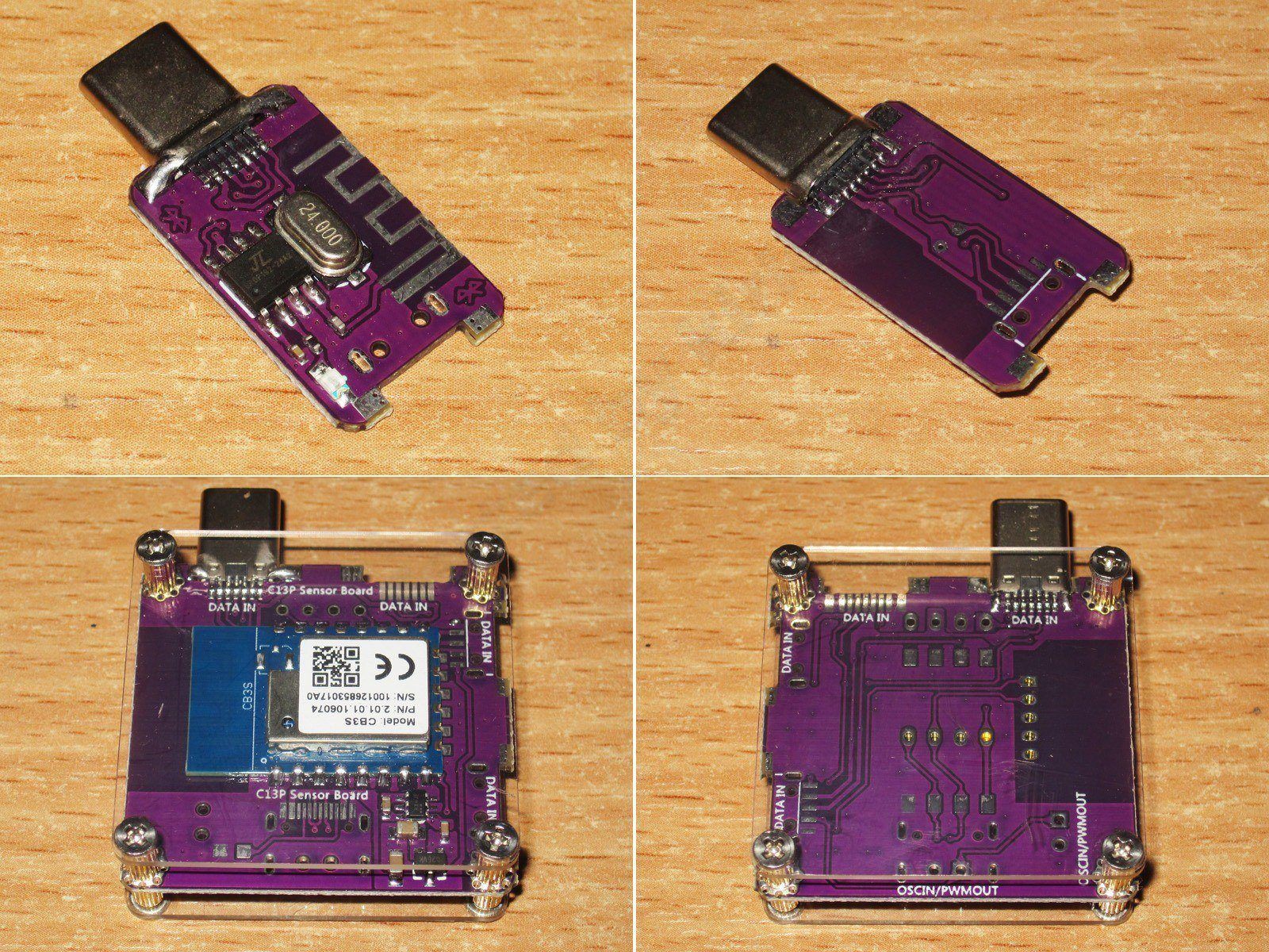
Bluetooth and Wi-Fi adapters. The manufacturer has now gone for a more versatile option, so you can choose which type of connection to use. Interestingly, the Wi-Fi board has pads for several different connector configurations.
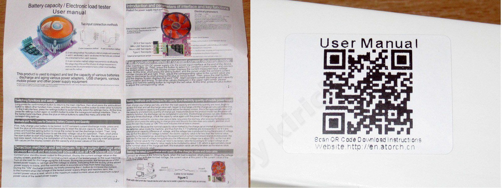
The package also included a manual, but it's easier to view it electronically. There's a link on the power supply box.
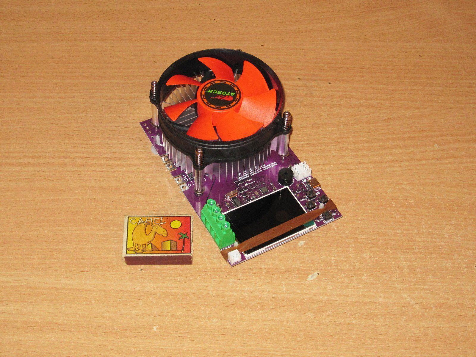
And here's the load itself. Yes, something about it looks very familiar...
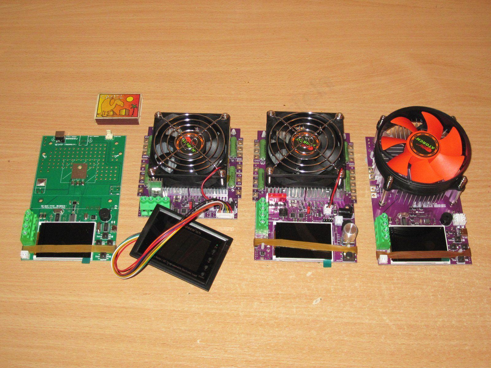
Almost all of Atorch's four-wire load models.
1. The first model, rated for 150 W, but with the option to raise the limit to 1000 W - review
1x. This should have been the DL24M, but I no longer have it. Here's the review.
2. DL24MP, the most interesting load, in my opinion. There's no full review, just a very, very brief look - link.
3. DL24EW, an expanded version of the DL24MP. The circuit design is largely the same, but there are some differences in the construction, and it adds the ability to control charging - review of the first revision.
4. Under review
There’s also a newer version of the new version, but as far as I can tell, the differences are cosmetic.
Yes, yes, and yes again: the new version looks very much like the old DL24. In some places, they’re practically identical.
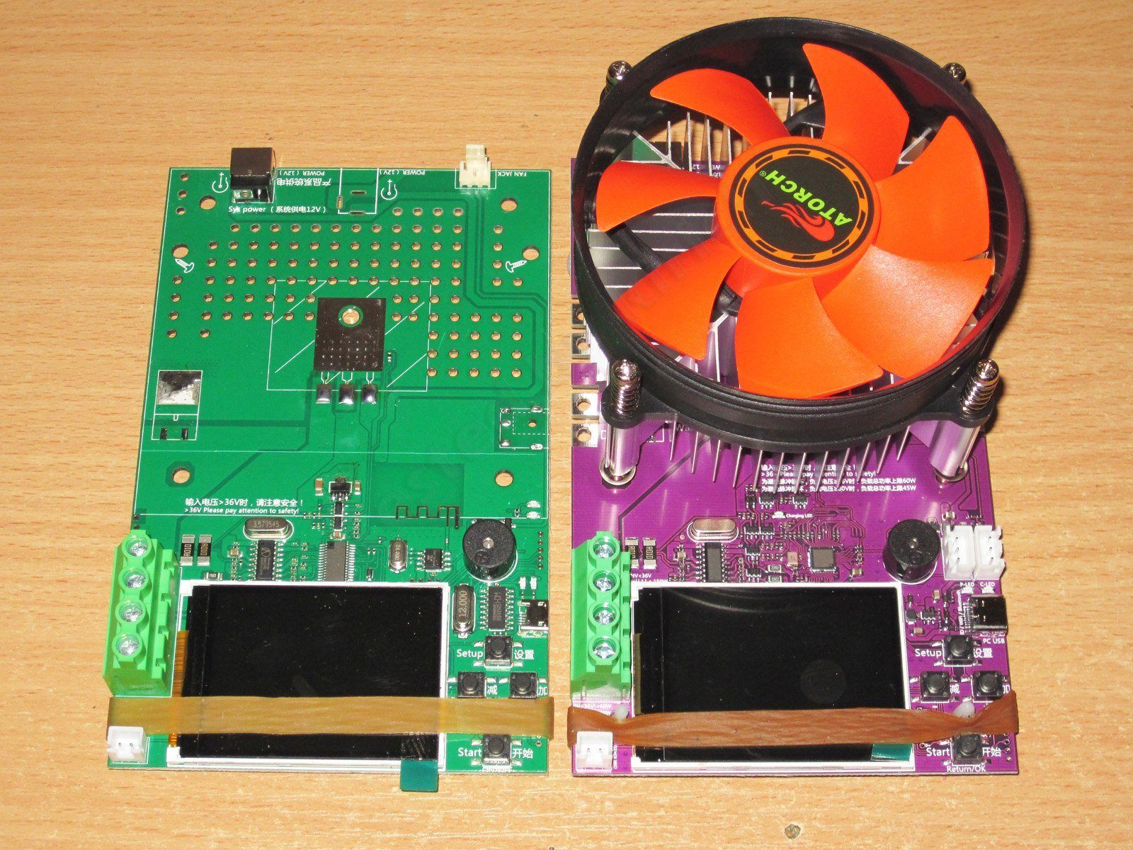
Just like before, there’s one transistor and a powerful SMD diode array under the heatsink, with the problems I’ll get to later.
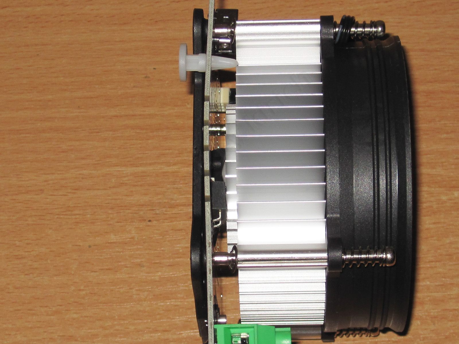
I noticed that the board has already warped because of the cooling system. The newer boards with four transistors handle this noticeably better.
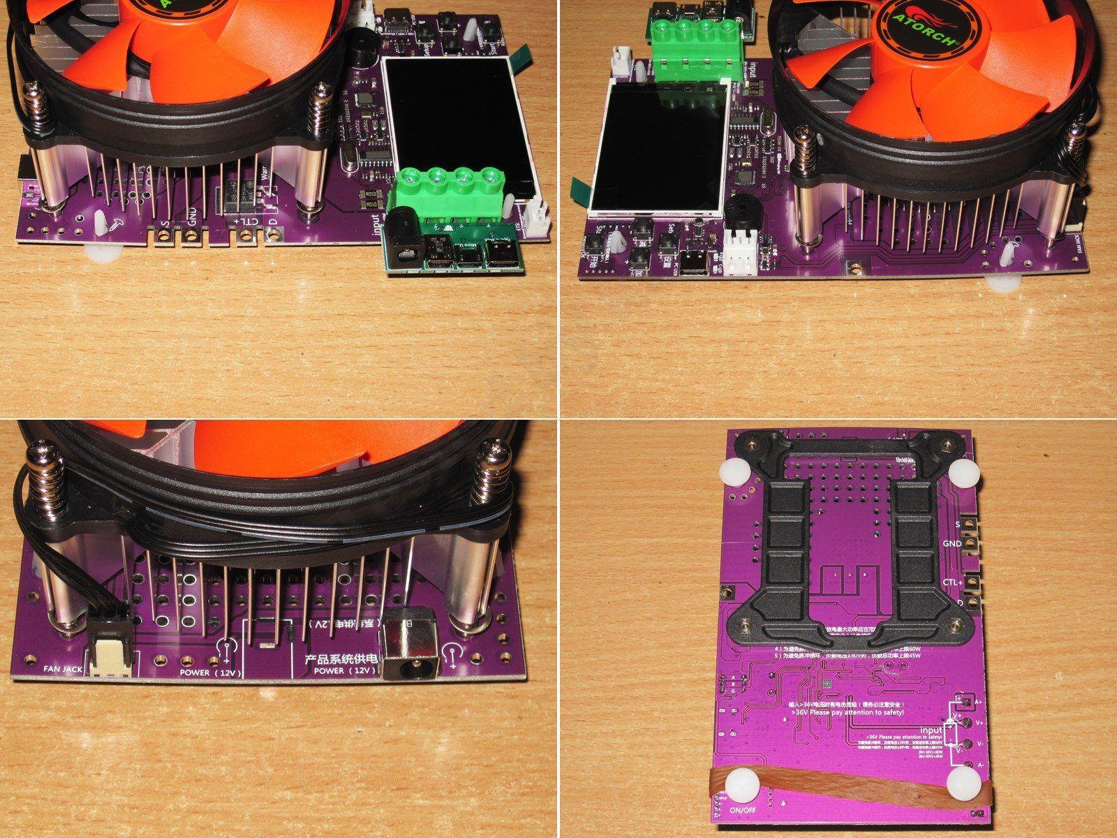
Let’s take a look at the new model.
1. On the left is the terminal block for connecting the power source, along with holes for connecting the charge-control module. Last time I complained that having it on the right was inconvenient, so they changed that.
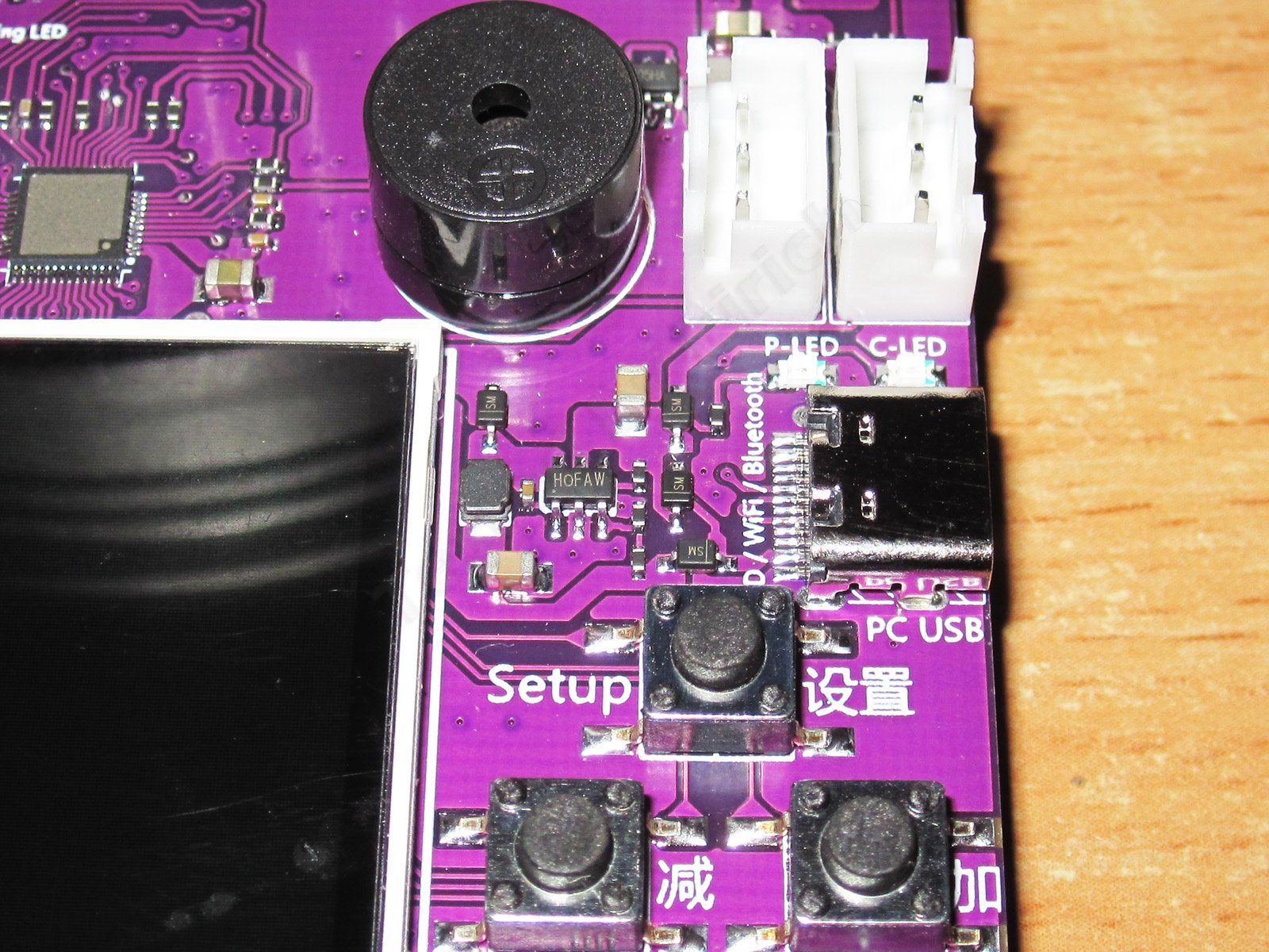
2. On the right is a USB-C port and a couple of additional connectors.
3. At the top are the external power connector and the fan connector.
4. The bottom is completely bare.
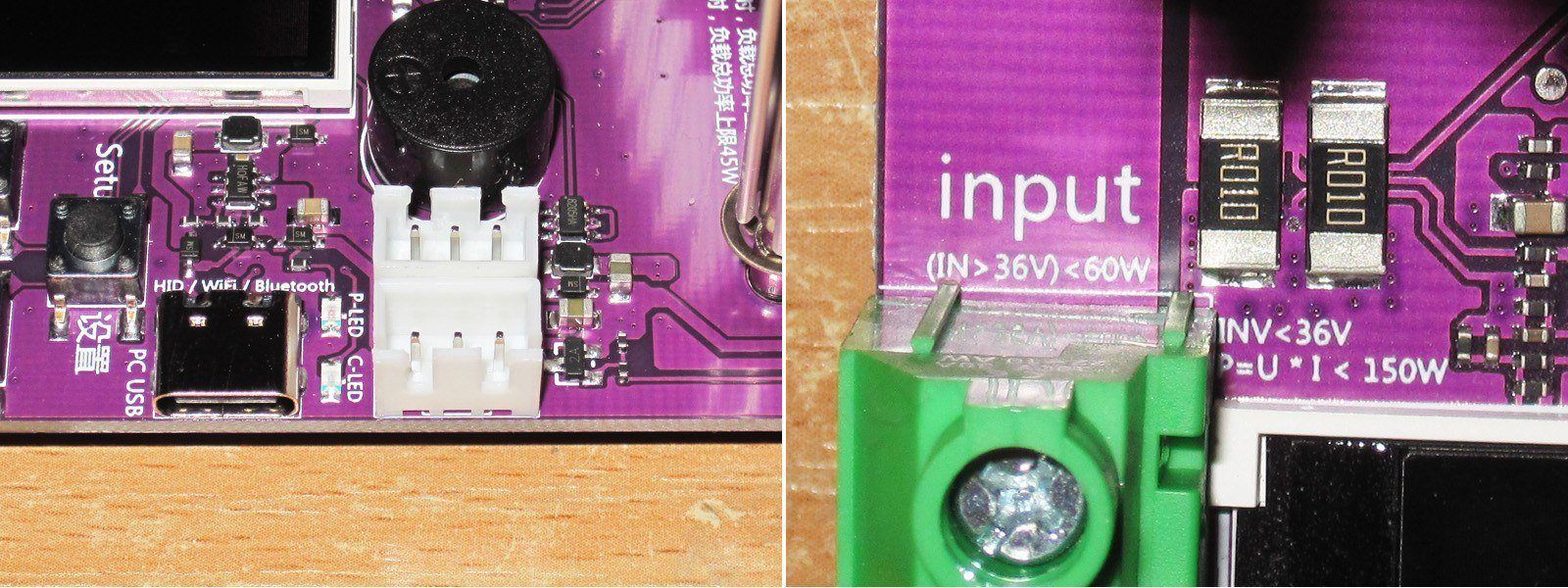
1. The two additional connectors are for linking two loads so they can be controlled together from a single piece of software. On the newer version, I think you can link up to four units this way. That’s why there are two connectors: one is effectively the input, the other the output. On the right, I spotted a switching power regulator; there had been complaints on the forums about the linear regulator overheating.
2. This is what I mentioned above. There’s a problem with having just one transistor, and it’s noted on the board: above 36 V, the power is limited to 60 W.
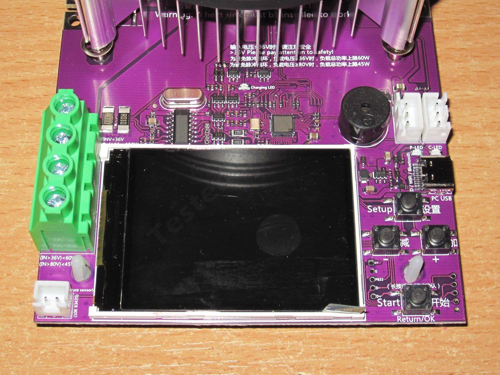
The front is practically identical to the old DL24. The external sensor connector is at the bottom left. I only just noticed the label next to it: above 36 V, maximum 60 W; above 80 V, maximum 45 W!
There are four buttons to the right of the display, again identical to the DL24. In fact, the load models’ names differ by just one letter.
Why they didn’t use an encoder is a big mystery to me....
The circuit design has clearly been revised, and the microcontroller is different. It also has:
1. A pair of 8205HA chips, each containing two MOSFETs.
2. Three LM321 op-amps
3. One GS8333 op-amp. Judging by the brief description, it’s a single/dual-supply, micropower, zero-drift CMOS operational amplifier, probably used to measure low current values.
Overall, there are more questions than answers. It’s hard to say much without redrawing the schematic. For example, I only found out that the CV mode on the 24MP and 24EW is hardware-based after redrawing that section of the circuit: it has two op-amps (for current and voltage) and a switch that selects between their signals. I don’t see anything like that here, but I do see some mysterious transistors and a couple of odd diodes to their left. If one array controls the fan and the charge module, what does the other one do?
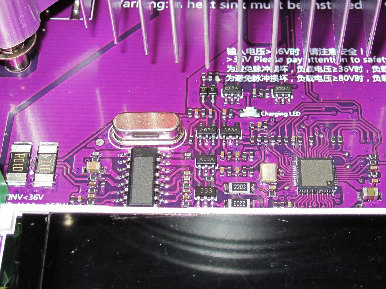
The markings on two chips have been erased. The microcontroller is a mystery, but the other chip is easy to identify: it was on the old board, and the board layout is almost identical. They’ve also gone back to using a pair of 10 mΩ shunts.

There’s a power regulator to the right of the display. The UART-to-USB converter is gone; the microcontroller handles everything now.
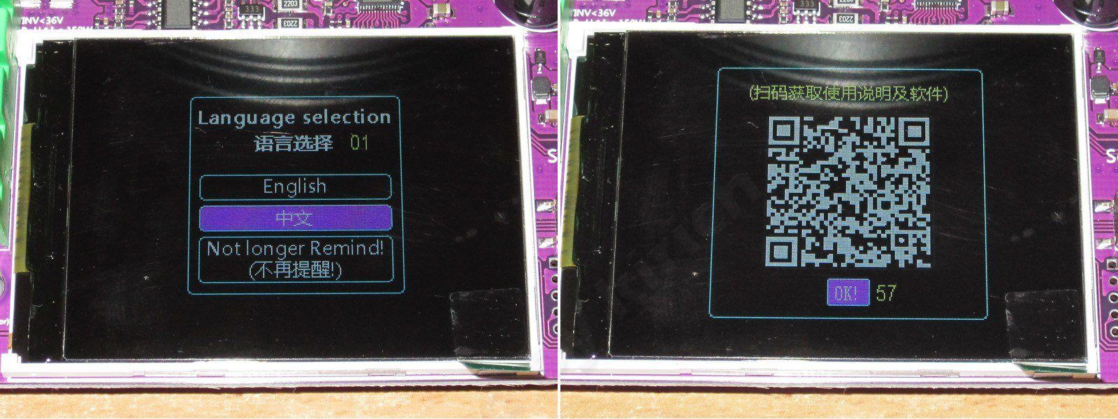
When we turn it on, it immediately prompts us to choose a language and displays a QR code linking to a page with a description.
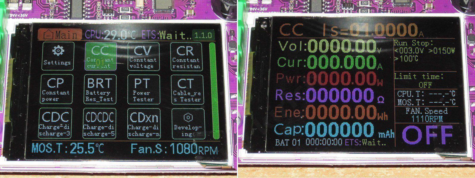
Next comes the operating mode selection screen, which after a short while switches to the CC mode screen, the default mode.
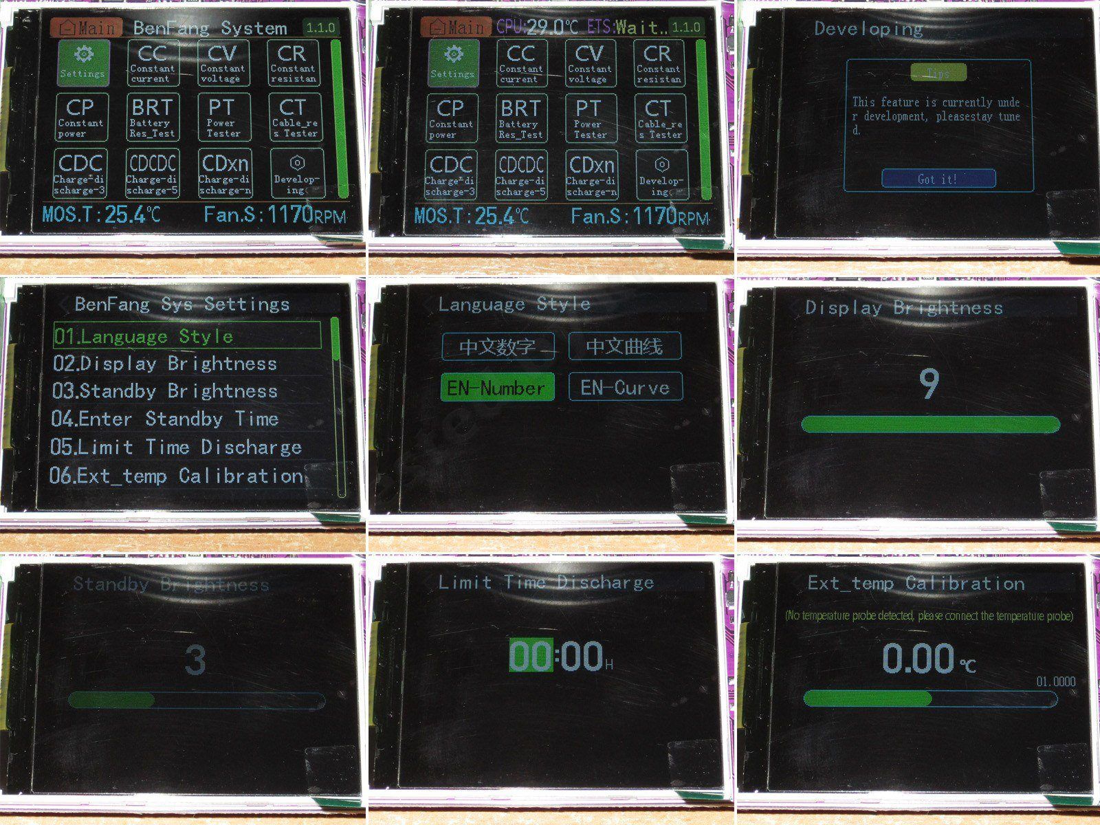
A guide to the control menu.
1, 2. The main screen. The top line cycles through the software name and version, as well as the microcontroller temperature (why?) and ETS (external temperature sensor).
3. There’s a Developing button at the bottom right, but it’s just a placeholder
4. The menu is extensive and better organized than on the DL24EW: the items are listed in order rather than jumbled together.
5. Language and display mode selection: digits or graph.
6, 7. Brightness in operating and standby modes.
8. Discharge time limit.
9. External temperature sensor calibration.
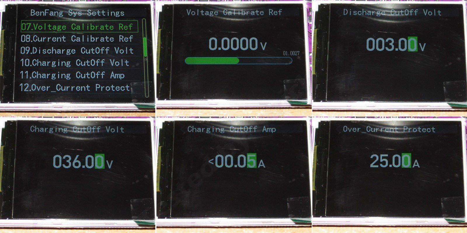
1. The second menu screen.
2. Voltage calibration; current calibration uses the same screen.
3. Discharge cutoff voltage.
4. Charge cutoff voltage. This is more of a protection feature than a primary one. It’s better to set this voltage a little higher than required so that cutoff is triggered by the current dropping.
5. Charge cutoff current setting. This is a very important feature. I’d probably set it to around 100 mA right away, though of course it depends on the battery.
6. Overcurrent protection. Unfortunately, the limit here is just 25 A.
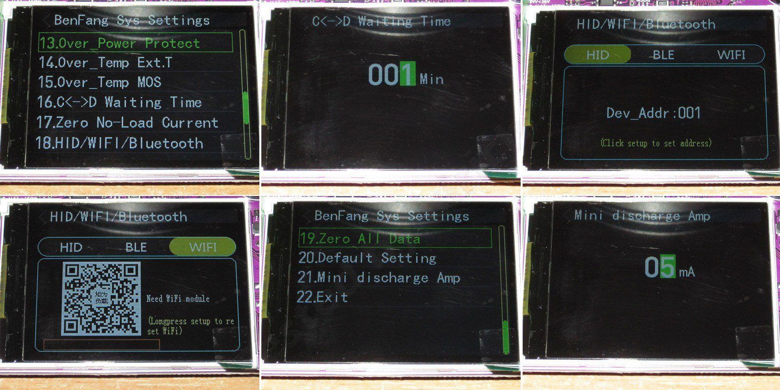
1. The third settings screen. I’m not listing everything, just the most interesting items; the rest are self-explanatory.
2. And here’s the setting the DL24EW doesn’t have, even though it’s very important: setting the pause between a charge-discharge cycle and a discharge-charge cycle.
3, 4. Communication mode settings menu. USB is selected by default; you can choose Bluetooth or Wi-Fi if you install the corresponding module, of course.
5. The fourth menu screen
6. The most confusing and novel feature here is the boost function when discharging at low currents. The description mentioned something about a function for testing batteries at low currents.
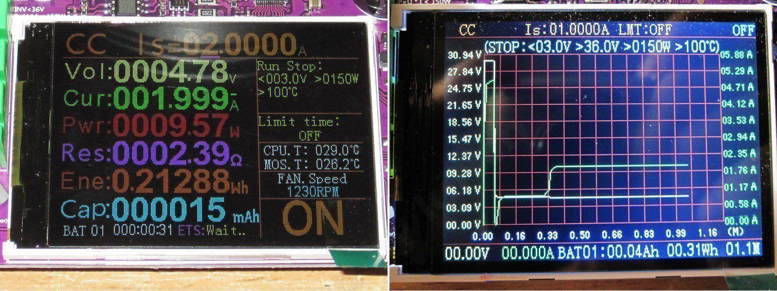
The main screen has been tweaked a little. For example, it now shows the fan speed (which is finally adjusted automatically), the transistor sensor has been renamed, and the indicators for the shutdown settings have been redesigned.
In graph mode, it basically shows the same thing as the app. For example, I tried loading a 5 V power supply with 1 A and 2 A.
A few tests.
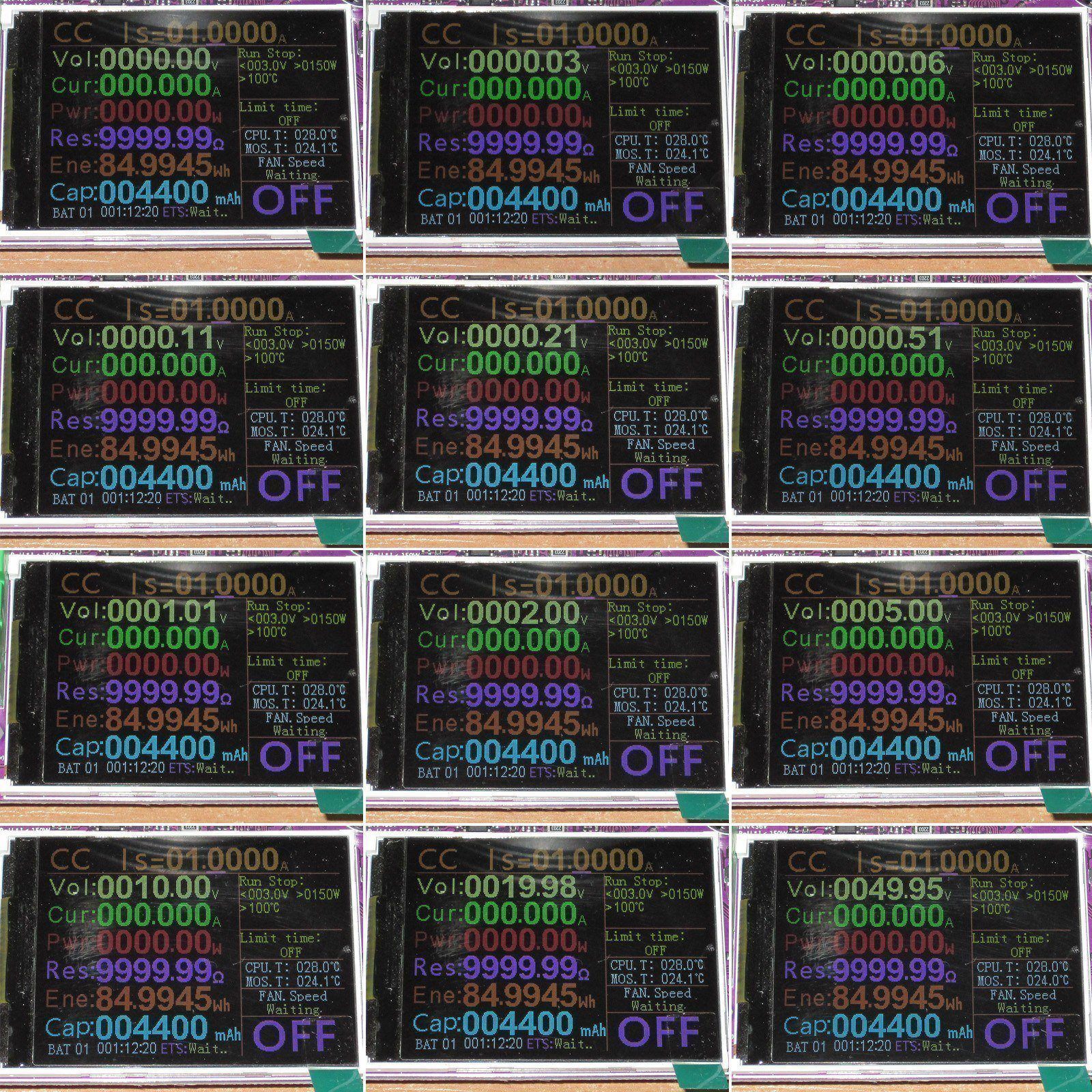
First, I checked the voltage. It’s basically fine: the range is 10 mV–50 V. The only issue is that the load didn’t register 10 mV at all.
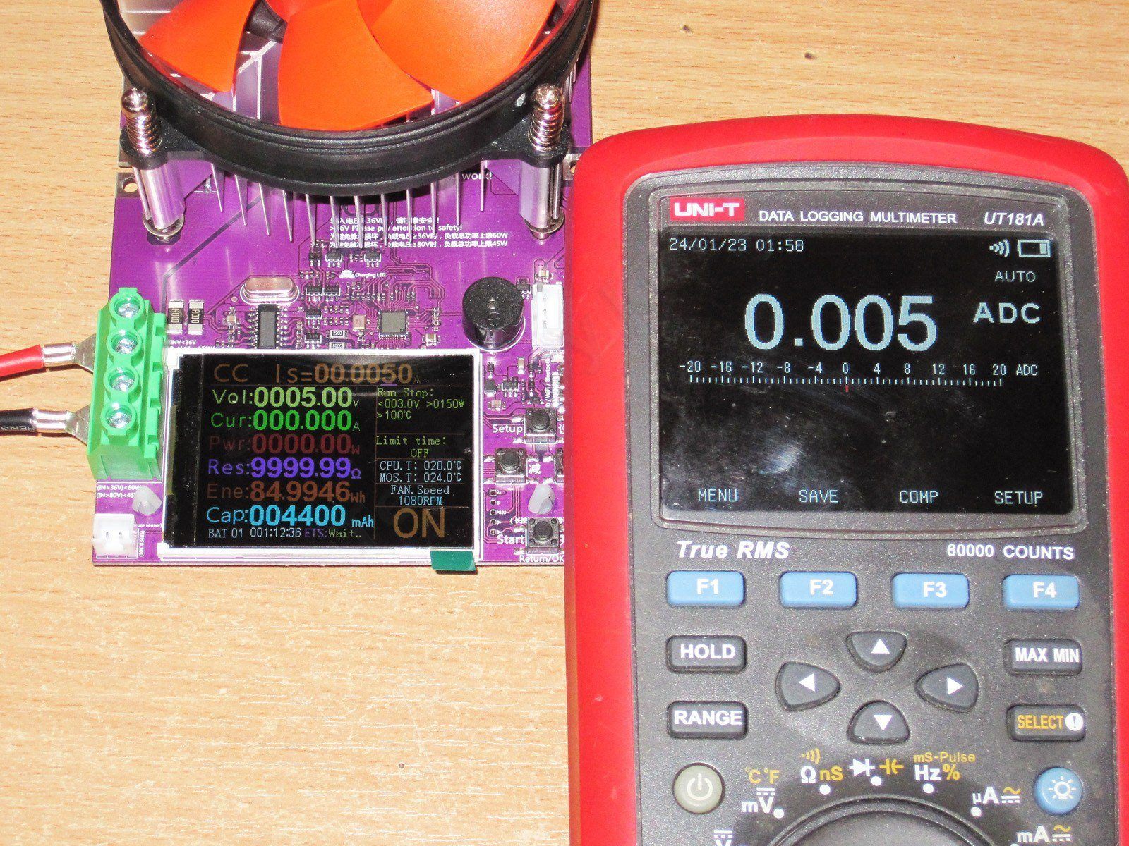
The current test turned out to be more interesting. I first set it to 5 mA, and to my surprise, the load set that current correctly.
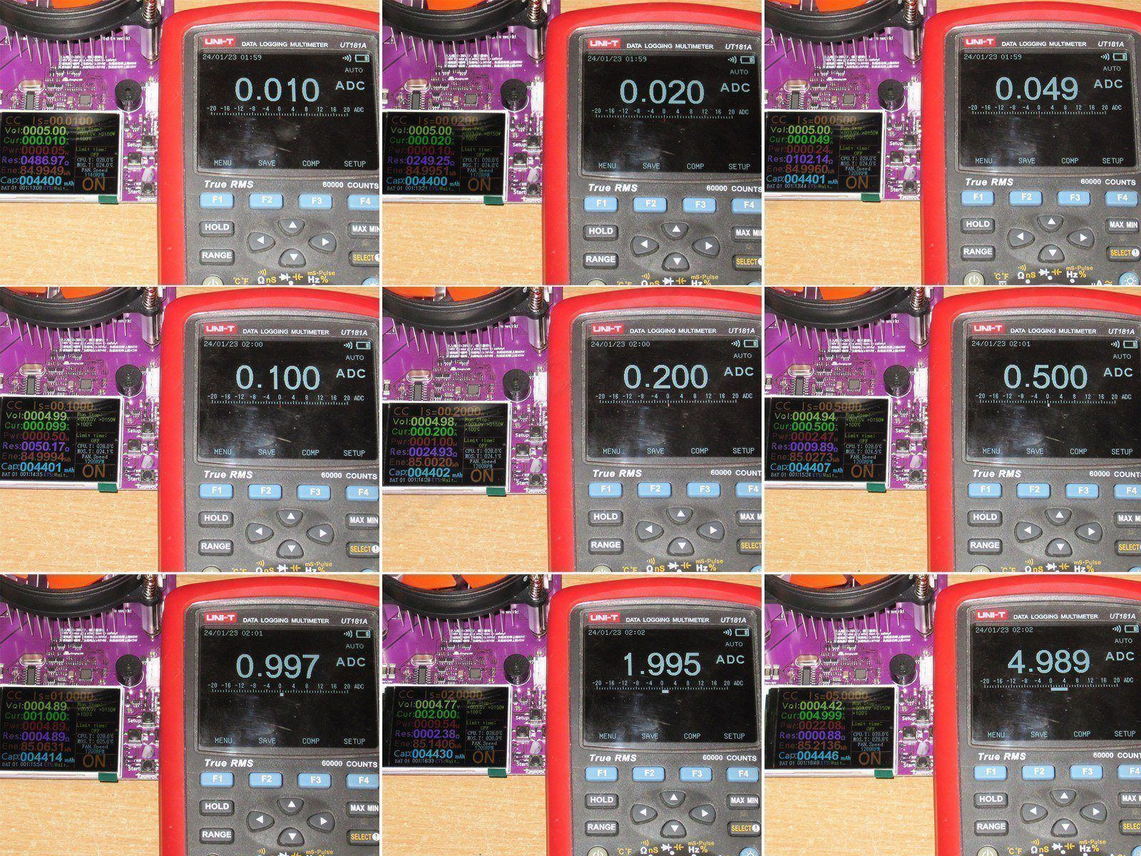
Further testing across the 10 mA–5 A range also showed that current setting accuracy is very good indeed.
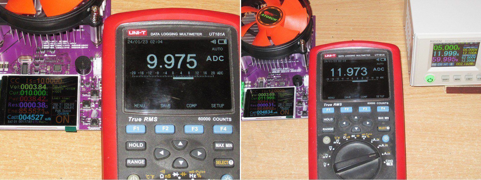
At the time, I had no way to test above 12 A. Still, the results at that current are more than enough to say that this load does a good job of setting and measuring current, and its readings match my RD6012P power supply exactly.
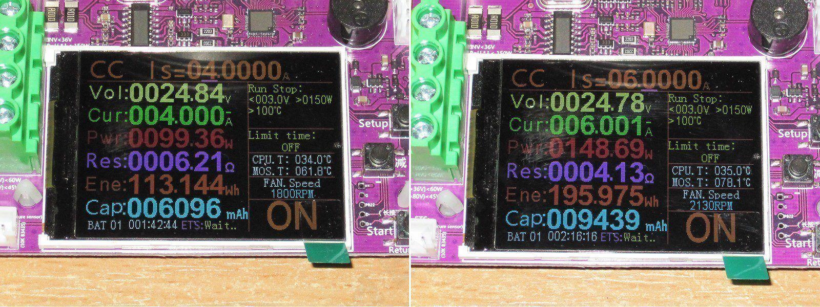
While I was at it, I also checked the thermal performance, first at 100 W and then at 150 W.
The fan is relatively quiet and ramps up very smoothly. I really liked it. The built-in temperature sensor read 62 degrees at 100 W and 78 degrees at 150 W. It looks very impressive, but doesn’t seem very realistic.
Unfortunately, reality is merciless: at 150 W, the transistor easily heats up to 120–125 degrees. And keep in mind, this was in winter, when it wasn’t particularly hot indoors. In summer, add at least another 5 degrees.
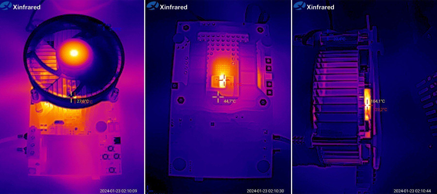
This is partly aimed at those who write in their ads:
Transistor temperature under sustained maximum load of 450W (600W): 58–61 degrees.
and displays pretty pictures from a temperature sensor measuring the air temperature. I've written several times that the sensor in these loads gives inaccurate readings. For example, I use temperature sensors with a different TCR to compensate for the error as best I can. On top of that, the sensor is pressed against the transistor case with thermal paste, and even then the reading is about 10–15 degrees too low. If I wanted, I could also make the temperature sensor show 60, 30, or even -40 degrees....

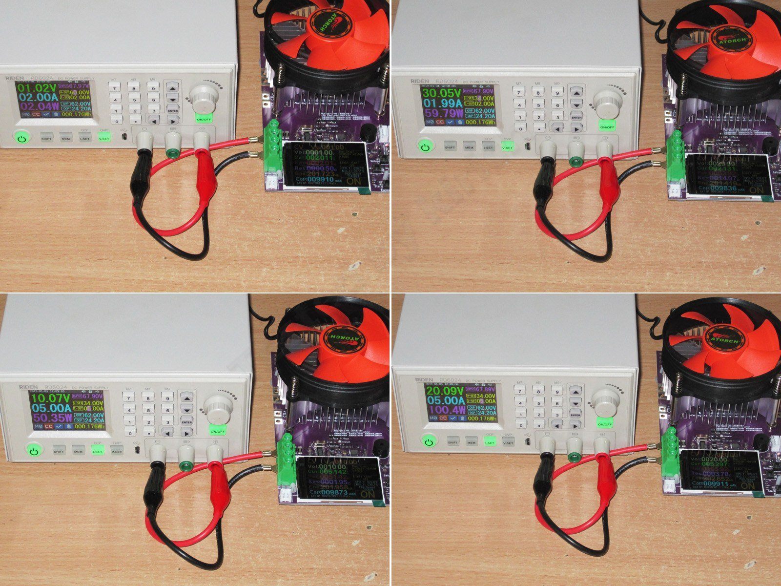
CV mode. I suspect it's implemented in software here, but let's check. First, a quick note: this mode is never used to test voltage sources, i.e. power supplies or batteries!!! CV mode is for testing current sources, such as LED drivers and chargers (actual battery chargers, not the USB power supplies you use to charge your phones). The current is set by the source itself, so the load will draw exactly as much as the source can provide.
First, I set the current limit to 2 A and started raising the voltage. From 1 to 10 V, there were no problems at all. The only thing is that the voltage settles rather gradually, initially overshooting the set value a little.
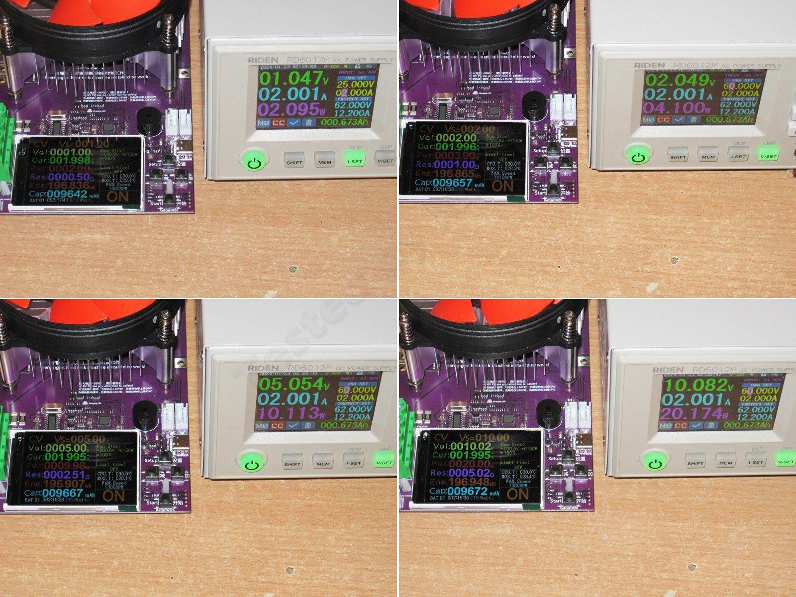
Okay, let's raise it to 20 V—and the power supply starts going haywire. The CC symbol is lit, the current is set to 2 A, but the measured current on the display is about 1.4 A.
I tried raising it further, but got an error saying I was asking for too much. This is a problem, by the way: even if you upgrade the power stage, you'll still get this error...
I tried 40 and 45 V; no difference. We get 1.2 A with 2 A set.
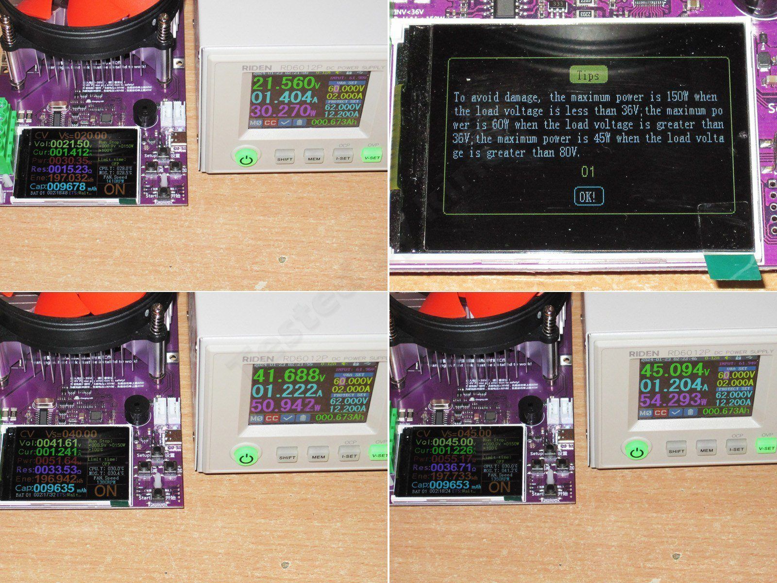
I tried setting 15 V at 4 A, and got the same thing: the CC symbol is lit, but the current is only 1.8 A. But I know this can happen with a “sensitive” power supply, and a capacitor connected in parallel with the power circuit often helps. I added one, and got exactly the same result.

Later, I decided to repeat the experiment, this time with a powerful, “sturdy” power supply. Everything worked normally: I set 1 and 30 V at 2 A, as well as 10 and 20 V at 5 A.
So, is the power supply to blame? No. During the test, the power supply terminals connected to the load with the supplied alligator clips were literally “singing”—or, more precisely, buzzing at a frequency of several kilohertz. Press them together and the buzzing gets quieter; let go and it gets louder.
The point is that they're buzzing in sync with the current ripple. I don't even need to get out the oscilloscope to check: you can literally hear the ripple without it.
So, unfortunately, I don't recommend using this mode.
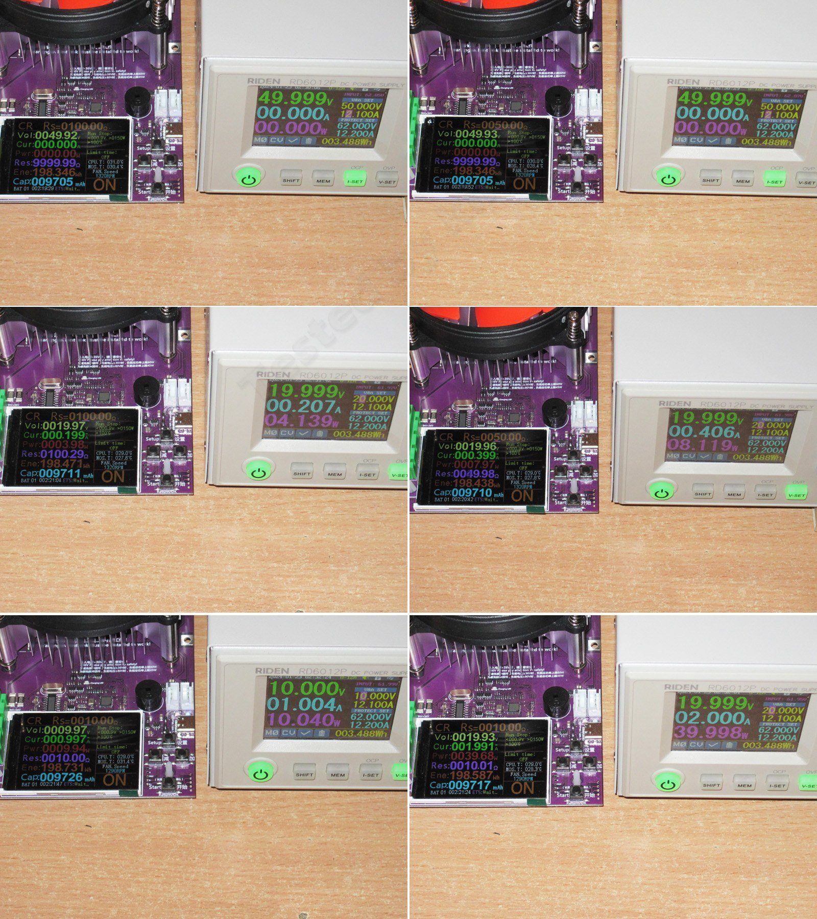
Let's try CR mode. By the way, does anyone actually use it? What for?
More odd behavior here. I set 50 V and tried equivalent resistances of 100 and 50 Ω; the current stayed at zero.
I lowered the voltage to 20 V. With the same 100 and 50 Ω settings, everything worked correctly.
I lowered the resistance to 10 Ω and tried 10 and 20 V; everything worked correctly.
So it seems that above 20 V it won't work, at least at 50 Ω, while at 20 V and below it works without a problem...
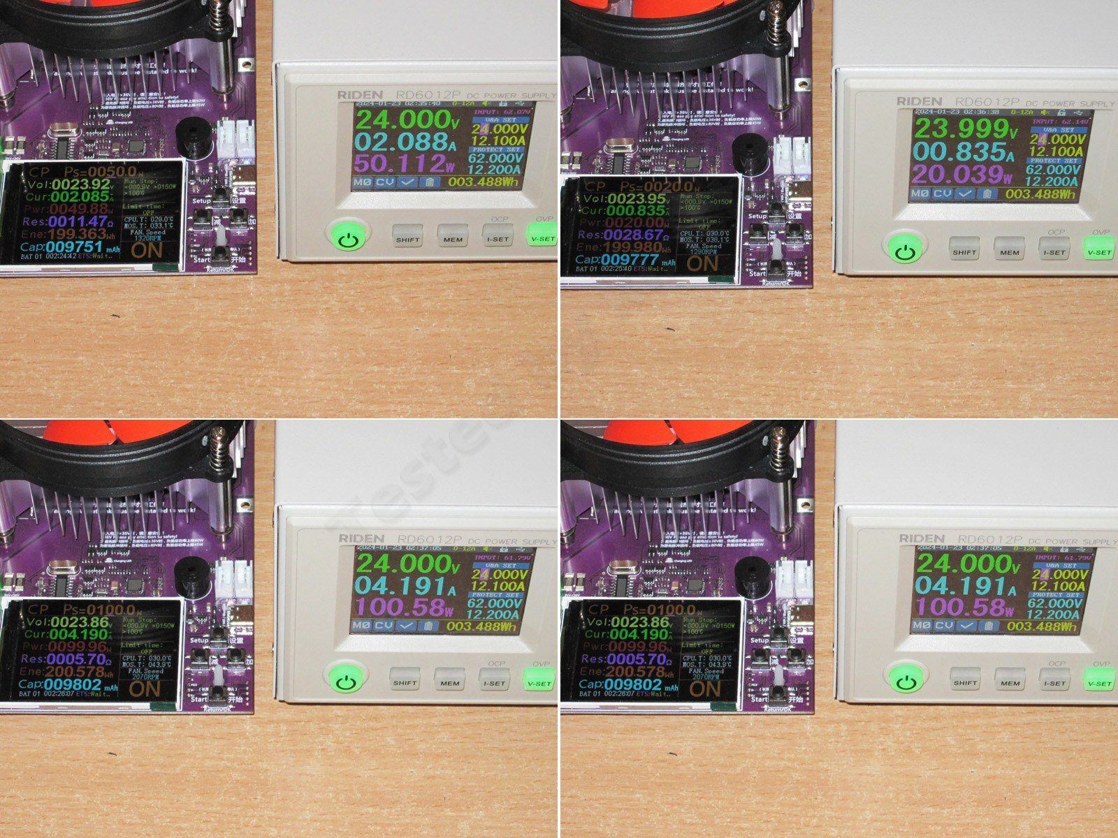
All right, let's try CP mode. I think this one can actually be useful.
I set the power supply to 30 V and the load to 5 or 10 W; in both cases, the actual power is about 6 W.
I lowered the voltage to 20 V and set the power to 20 W; it worked correctly.
I raised it to 30 V and set the load to 50 W, but got only 27 W.

All right, let's keep experimenting.
With the load still set to 50 W, I lowered the voltage to 24 V; it worked correctly. I lowered the power to 20 W, and that worked fine too.
Okay, I tried raising the power first to 100 W and then to 150 W, with no problems. Though afterward, a message popped up saying the 150 W limit had been exceeded.
So it seems the load works correctly as long as the voltage is below 24 V. Above that, it starts acting up. Apparently, the same goes for CR mode too. What a shame.
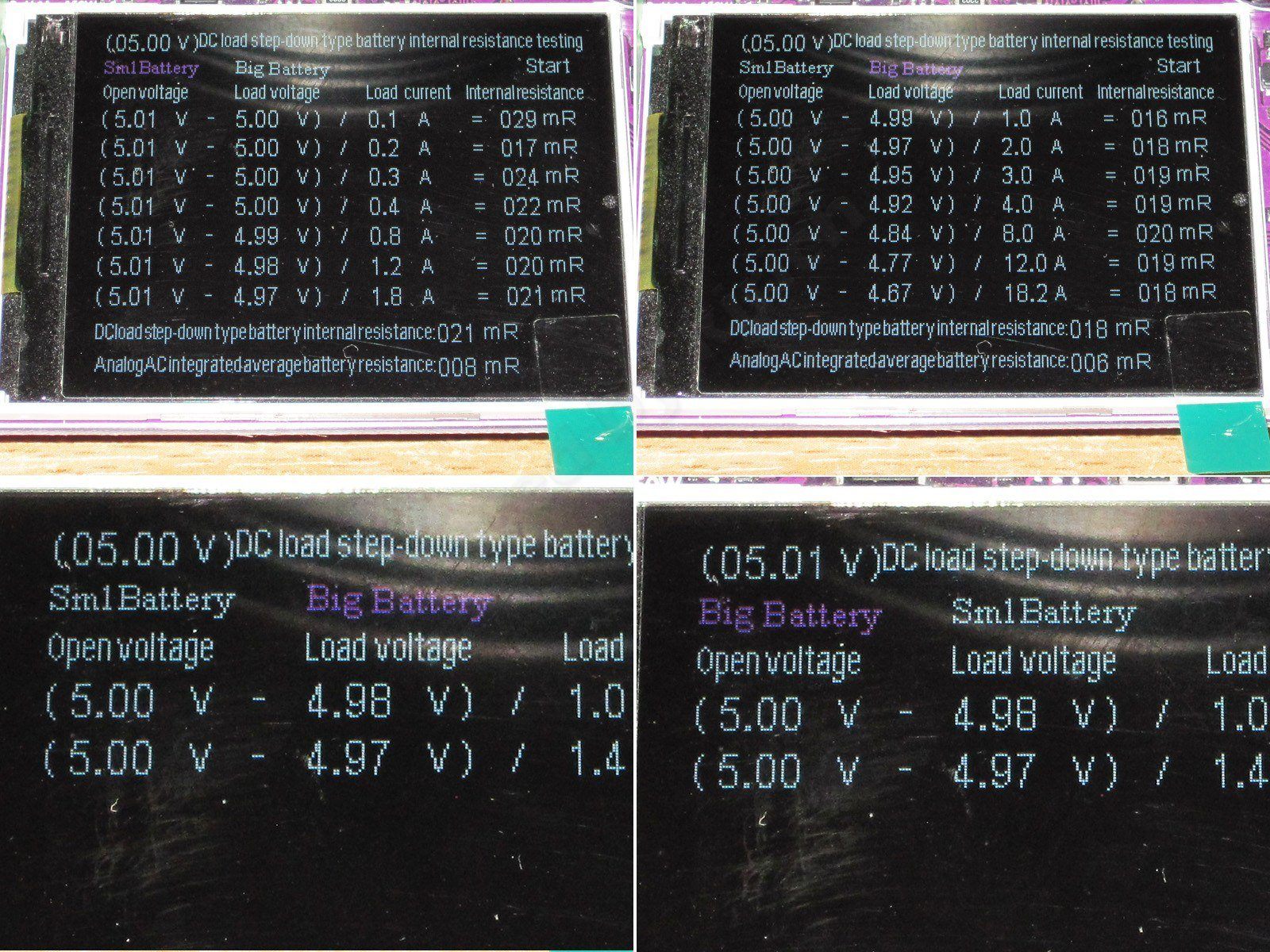
A few more modes. First, measuring a battery's internal resistance—in this case, I'm using a power supply in its place.
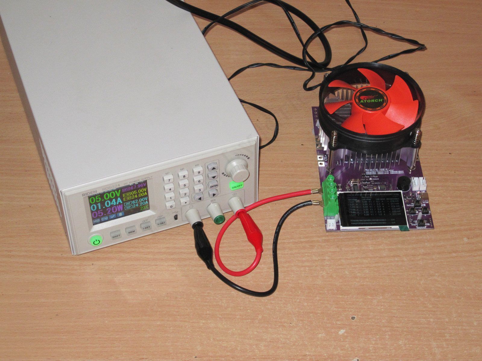
Well, nothing new here; it measures something.
But there are bugs too. For example, you can choose “large battery” or “small battery”; the difference is the test current. But you can select “large,” and when you confirm, the options switch places. Then you change something else, and they switch back. As far as I remember, I ran the first test with “large battery” selected, but the measurement was performed as if it were a small one. So be careful.
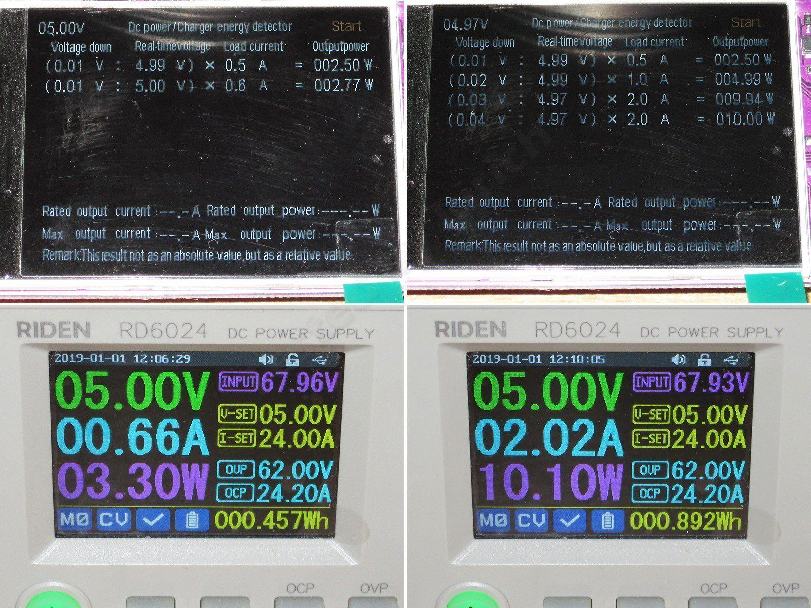
Testing the load capacity of power supplies.
This seems pretty good overall, but just like the 24EW, the test is extremely slow—really slow. For example, changing the current from 0.66 to 2.02 A took about 3.5 minutes, i.e. For the 25 A source test, the test will take about 45 minutes... brutal.
Developers, please make this test faster—at least 10 times faster!
While running the previous test, I noticed USB pads to the right of the display. Interestingly, a signal called PB22 is routed there too. But keep in mind that V+ is connected to the input, so if you power it from 12 V, you'll have 12 V on this pin as well!
The cable resistance measurement test seems pretty approximate to me, but at least it runs faster than the previous one.

Now for a more interesting test: charge control and, specifically, measuring battery capacity.
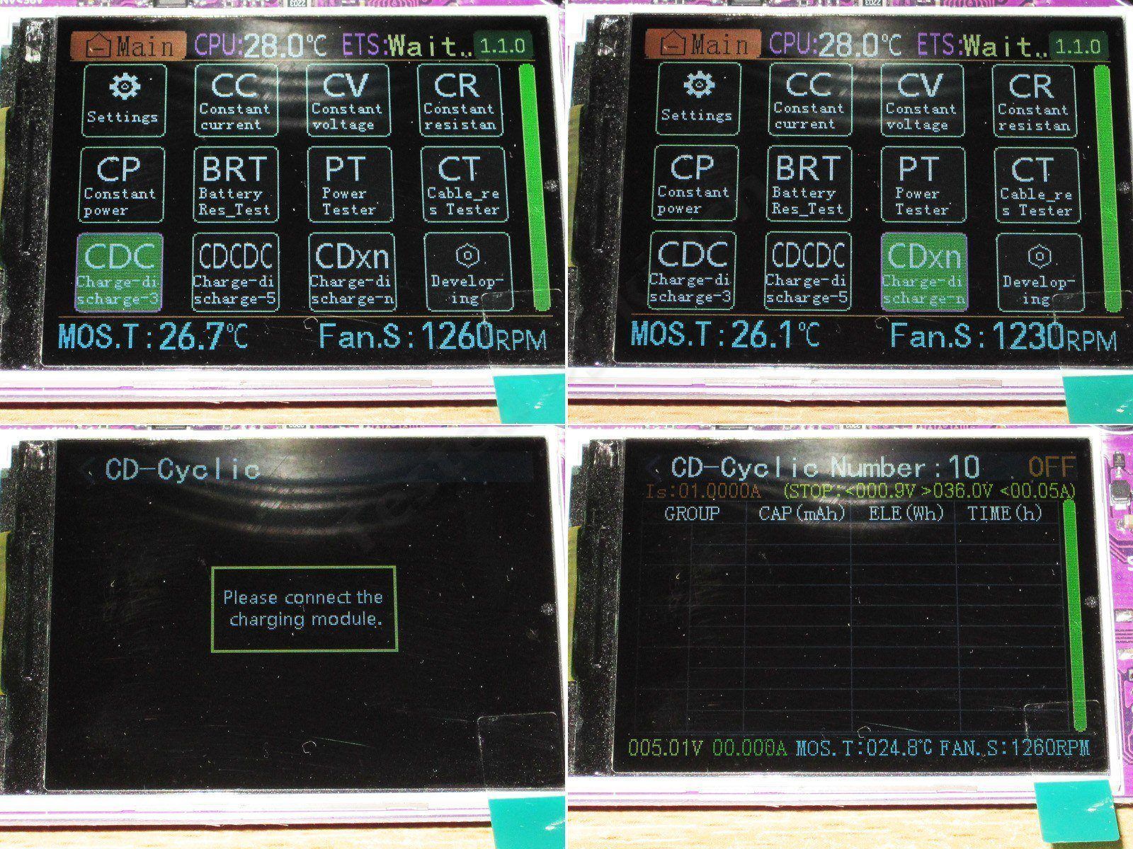
Before moving on to this test, though, I should mention the new cycle test. The original CDC test was charge-discharge-charge, essentially one cycle with an initial charge. There was also a second option, CDCDC, meaning two cycles.
Now they've added a multi-cycle test where you can set the number of cycles, and the electronic load displays the results in a table. I think that's handy.
By the way, before starting any of these tests, the load reminds you to connect a charger.
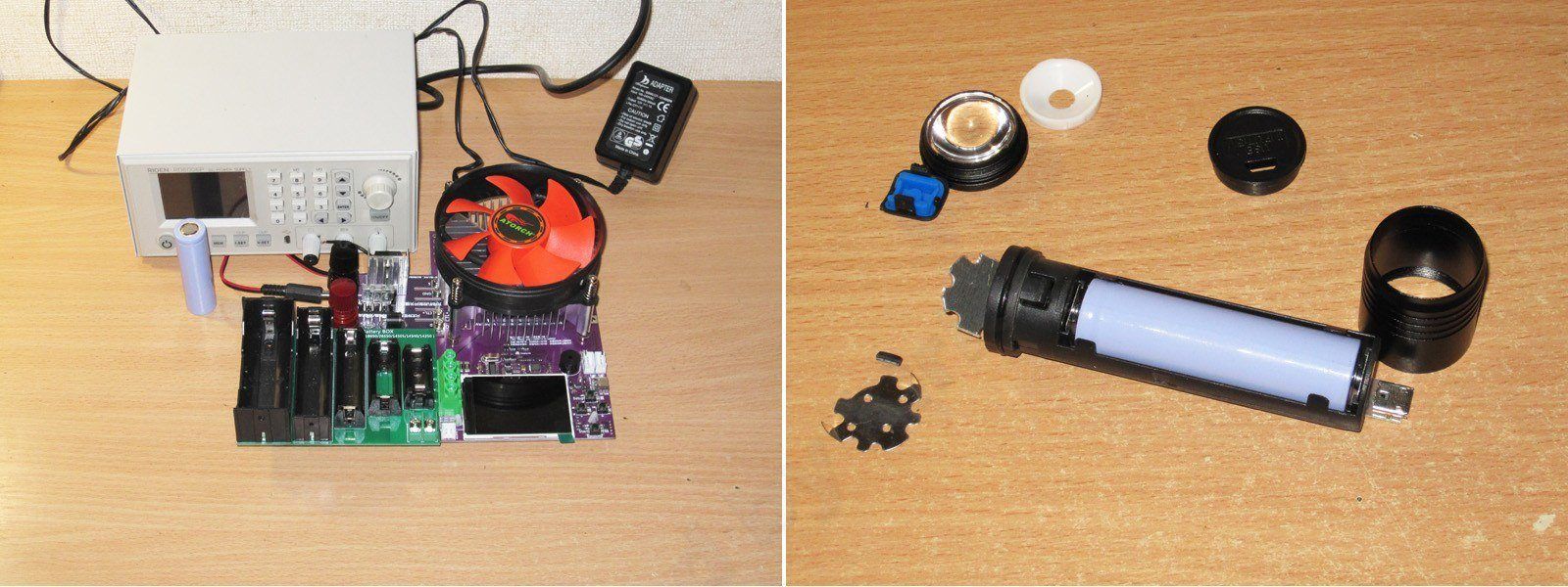
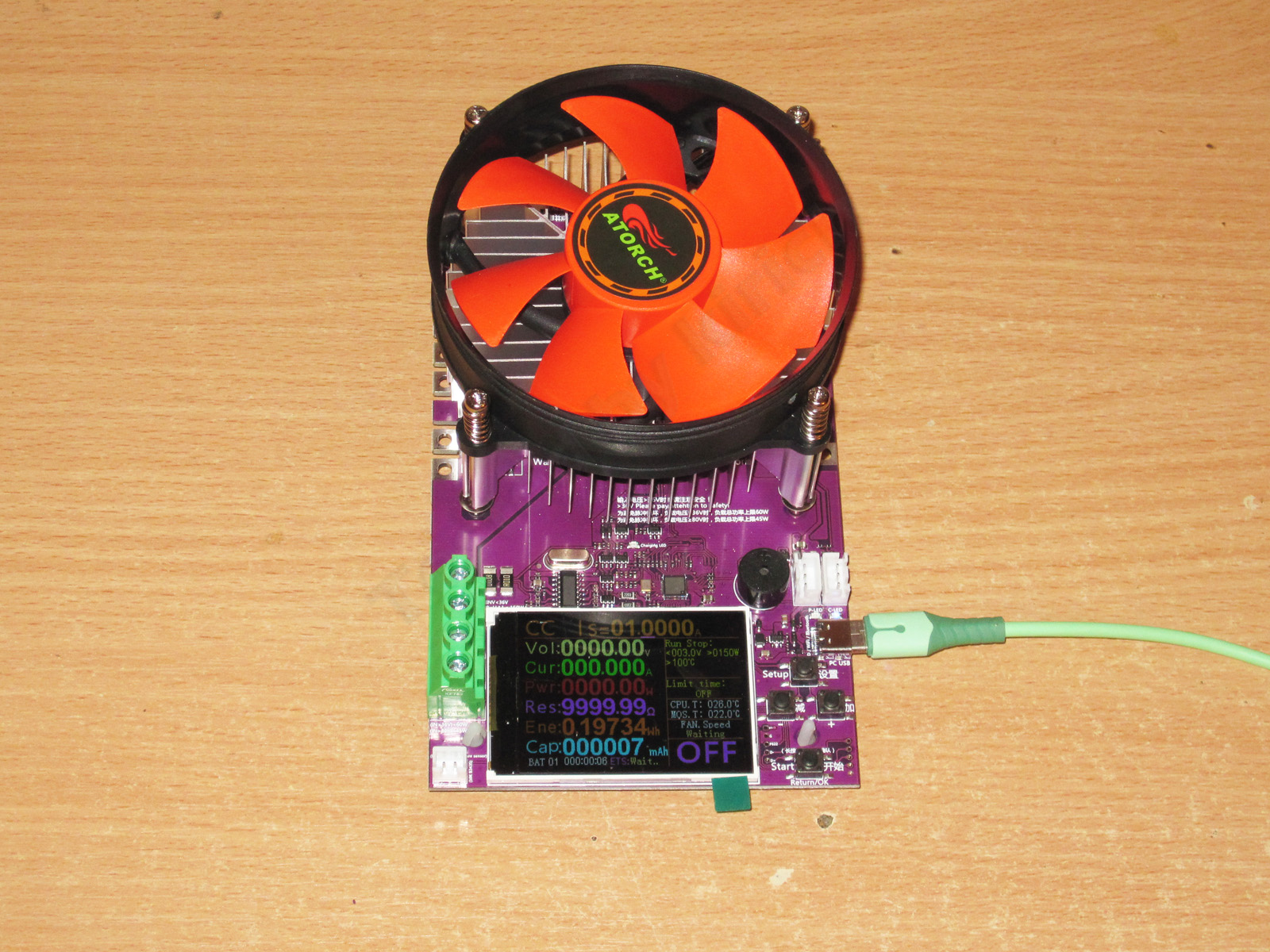
While I was waiting for the power to come back on, I put together the setup needed for automatic charging tests. As luck would have it, I also had a test battery to hand: I bought something on AliExpress and got a flashlight with a built-in 18650 battery as a free gift.
By the way, I almost forgot: while assembling the whole setup, I suddenly discovered that the kit didn't include screws for attaching the charge control board. I had two loads, and both came with this board but neither included any screws or nuts.
Also, the large heatsink makes it extremely awkward to screw the board in place. One good thing is that the board doesn't get in the way of installing the board with the battery holders. At least they thought of that—probably by accident.
One more reminder: the new control board has a protection diode that seriously interferes with normal operation, as I mentioned at the beginning of the review.
The rest is simple: set the charge termination voltage and charging current on the power supply, then set the discharge cutoff voltage, discharge current, and charge termination current on the load. Connect the charger and switch on the load.
Since there's a diode at the charge control board's input, I played it safe and immediately raised the voltage from 4.2 to 4.7 V. That turned out to be too much—the diode drops about 0.3 V. The drop is greater under load, of course, but since the load cuts off at 50 mA by default, you need to check the drop at that current. At higher currents, check what the voltage drop is there too.
1. During the first “charge” cycle, I noticed that I'd forgotten to set the discharge cutoff voltage. It was set to 0.9 V, but in my case it should have been 2.5 V.
2. I switched it off, changed the settings, and started again. On restart, the load asked whether to cancel the test (the default), continue, or start a new one. Very convenient—and the 24EW had this feature too.
3. A minute after charging, discharge began at the set current of 1.5 A.
4. A minute after discharge, charging began at the 1 A current set on the power supply.
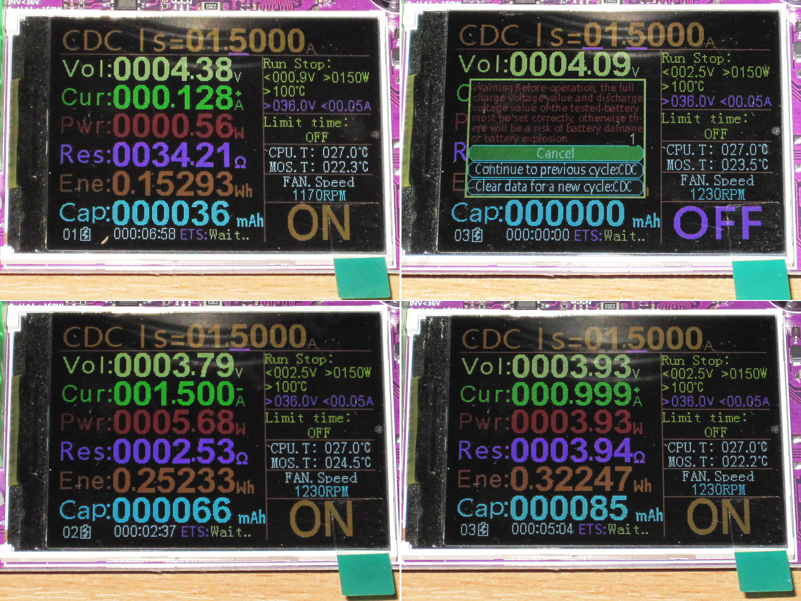
If the test finishes automatically rather than being stopped manually, the results for each stage are displayed on screen one after another.
The battery from the flashlight managed a whole 650 mAh. The results from the third cycle are a little lower; I sped things up a bit on the charger itself, which has nothing to do with the test.
After the test, if you go into settings and switch the display format to a graph, you'll see the complete test graph with all its stages. That's handy in its own way, but the main thing is that the load stores every stage in memory. I wonder how much memory it has. The 24EW did the same thing, though.
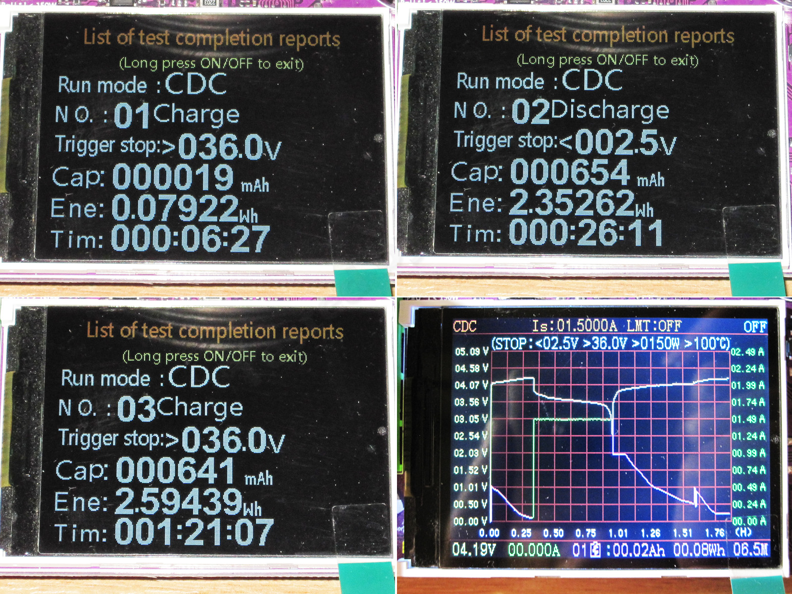
That covers charging. There's nothing new here apart from the multi-cycle test, which is essentially just an expanded version of the two basic modes.
Now let's see how the software is doing. The manufacturer says it's been updated.
I connect the load to my computer. It turns out it runs just fine from a USB port, but there's a catch: the controller works, but the fan and charge module control don't. So be careful: if you accidentally disconnect the main 12 V supply while USB is connected, the load will appear to be working, but the fan will be off—and you could burn out the power transistor.
The board does detect the fan speed: if you stop the fan, it displays “Waiting,” but it doesn't trigger an alarm. I wish it had that kind of protection.
The software starts in Chinese. There's a language selection button in the upper right, but it doesn't remember your choice, so you have to select the language again after restarting the software.
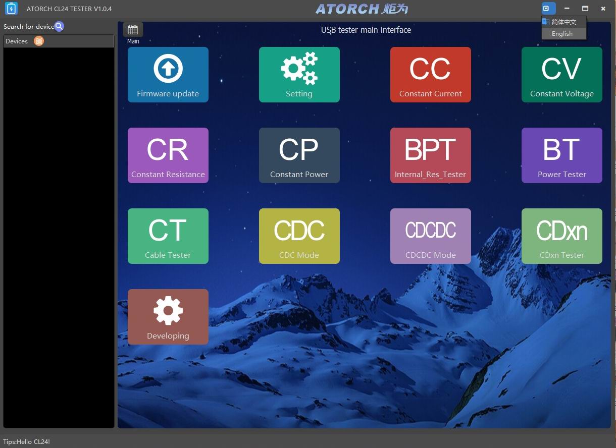
The software detects the connected load automatically and connects to it right away. Really convenient.
The interface has been completely redesigned, and definitely for the better. The old software was so sluggish it was unbearable—anyone who’s tried it knows.
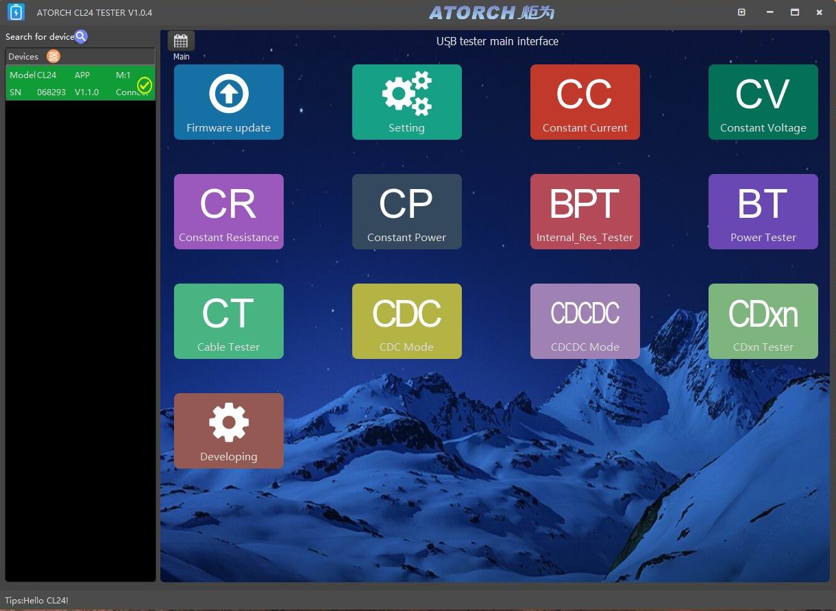
Unfortunately, the software doesn’t load data saved in the load’s memory. I could see the graph on its screen, but the software starts “from scratch.” That’s a real shame—I’d like to be able to run tests offline and then work with the results on a PC.
In my opinion, the controls and display elements aren’t organized very well; it feels like everything has just been thrown together. In that respect, the ZKEtech load interface is simpler but better thought out.
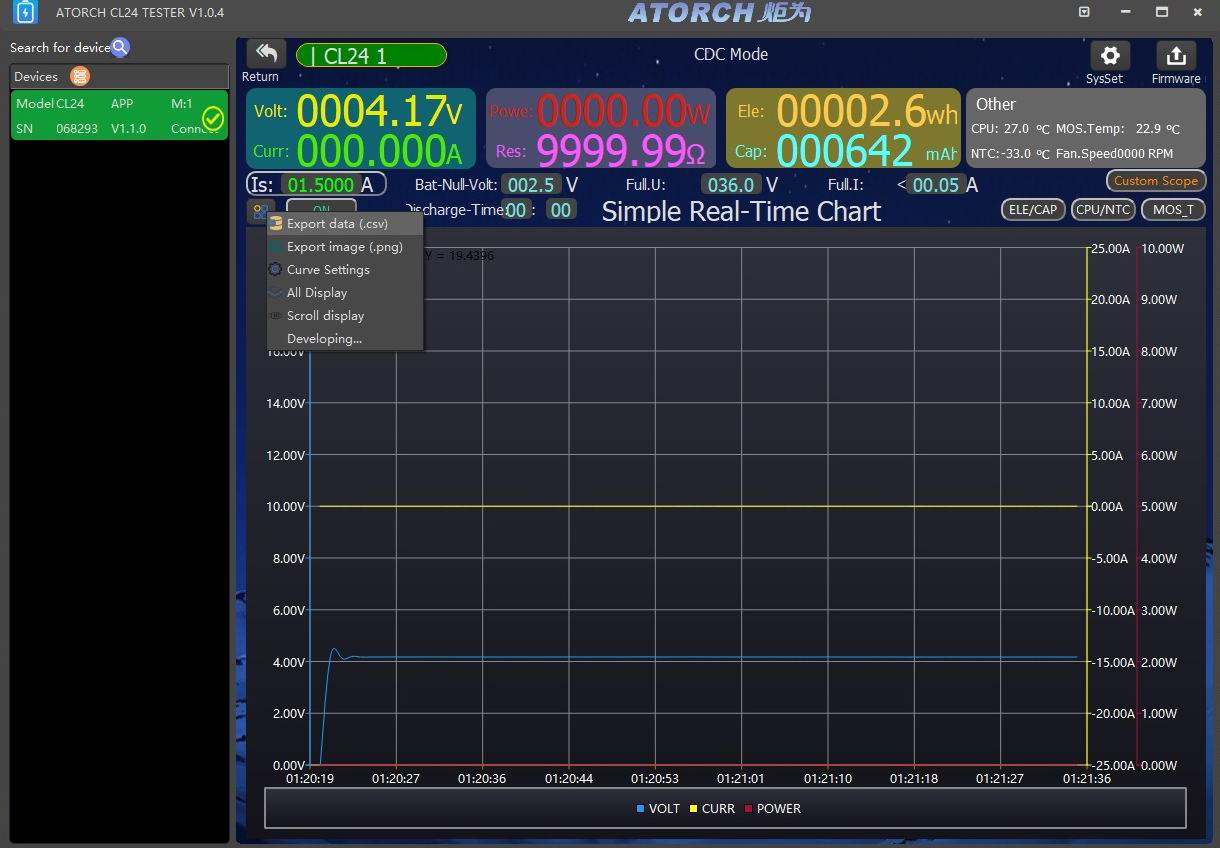
1, 2. There are lots of options, and I also liked the display settings: you can choose both what to show and how to show it.
3. You can also configure the load itself.
4. But when I tried to enter the repeated test mode, it said “in progress.” The CDC and CDCDC modes work fine.
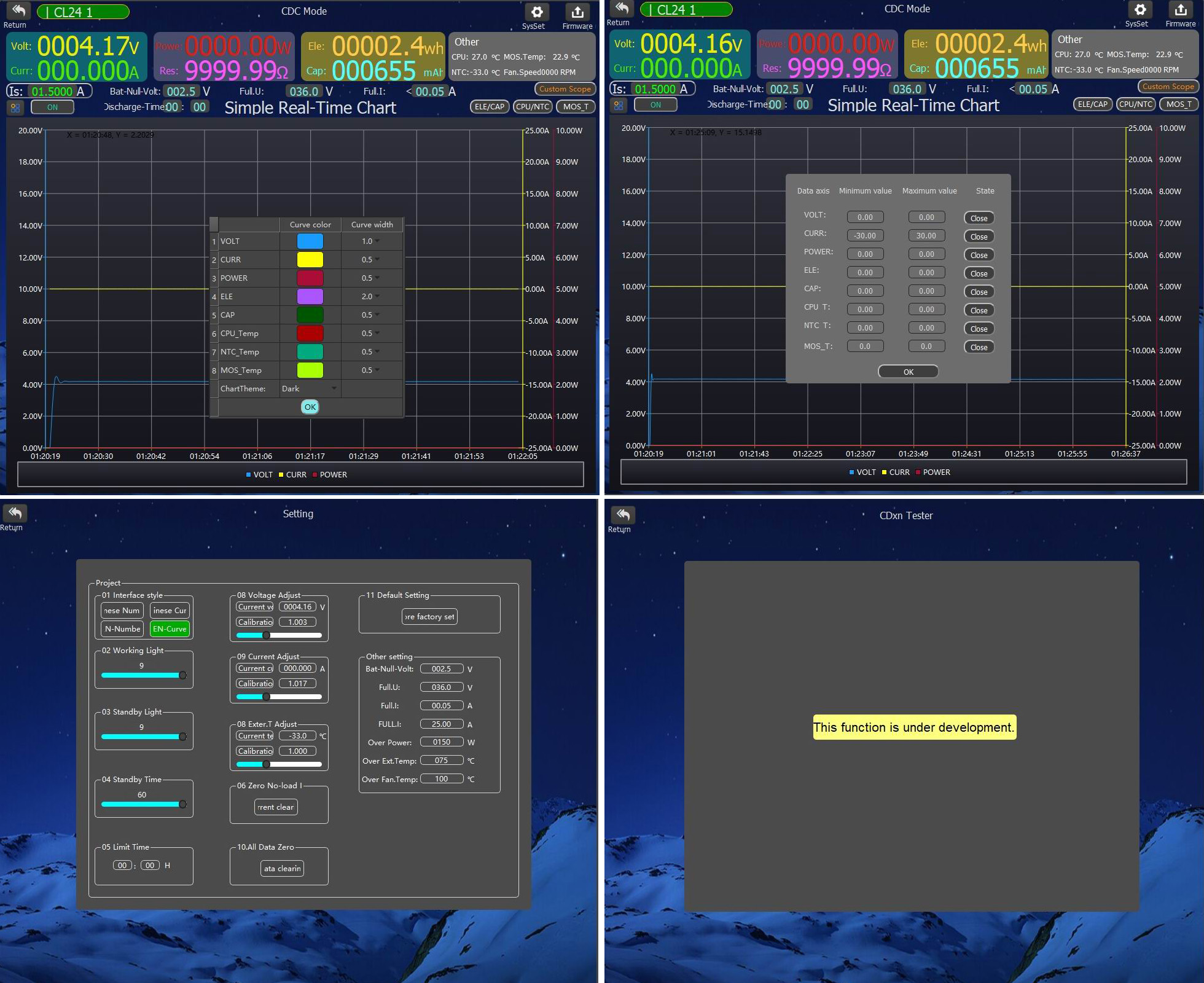
There are two ways to save the results. One is as a CSV file, which saves a lot of data at once. By the way, do we have anyone who could make a CSC-to-CSV converter that also changes the data format?
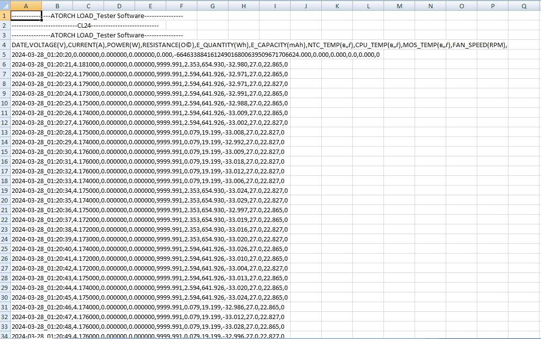
You can also save just the graph as a PNG.
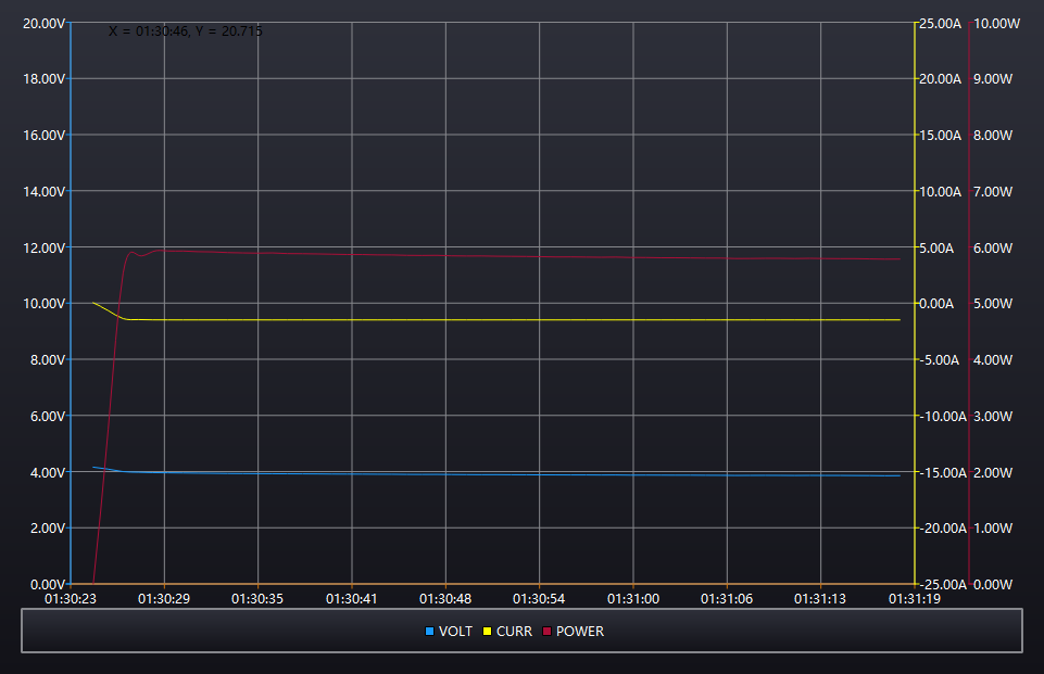
But what I was much more interested in was testing two loads controlled by a single piece of software.
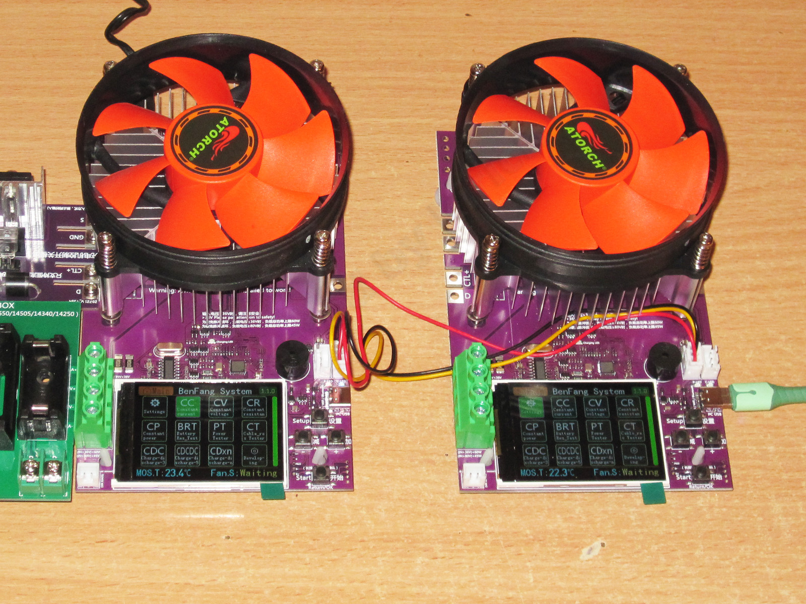
To do this, take two loads and connect them with a cable. Each load has a pair of connectors, but they’re equivalent because they’re wired in parallel. The interface is generally reminiscent of classic RS485, with all the devices on a single bus. Incidentally, the board contacts are marked “ground,” A, and B. And one more thing: the new version of this load can connect more than two loads, which makes sense—otherwise, why put two connectors on each load?
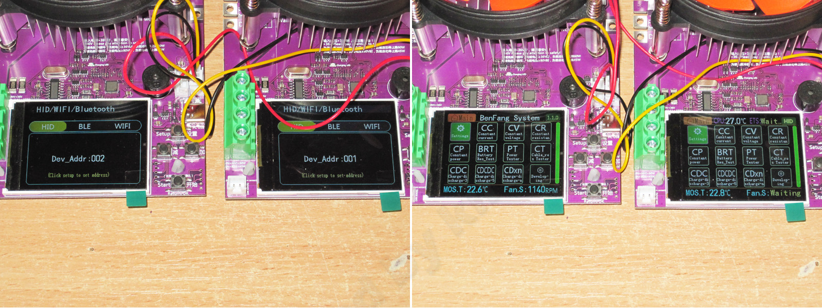
Next, open Settings and change the address of one of the devices under USB—for example, to 002—so they have different addresses on the network. Save by pressing the on/off button, then exit this menu. That’s it.
If you’ve done everything correctly, pressing the Search for devices button (and sometimes even without pressing it) will show you two loads.
One will be the master and the other the slave, marked M and S. But here’s what’s interesting: my master is correctly listed as number 1, while the slave is number 3, even though I set its address to 002.
I also found a strange issue: both devices show the same serial number.
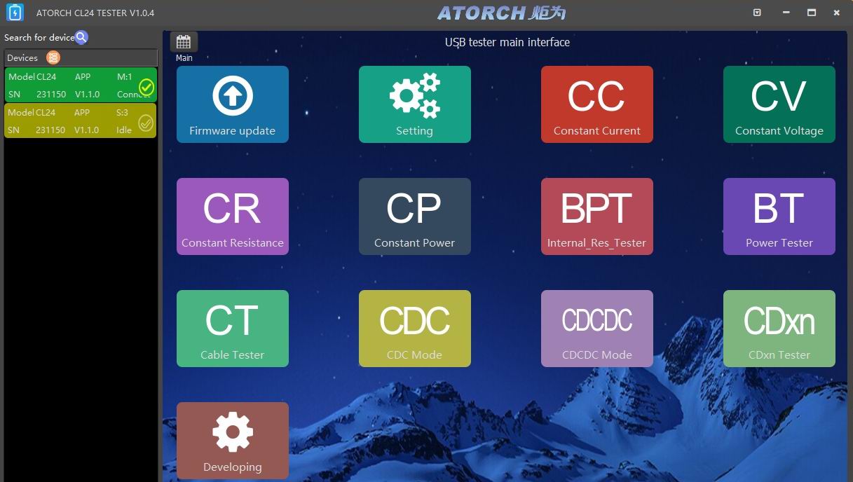
To control one of the loads, click its tab on the left. Yellow means inactive, green means active. You can make both inactive, but you can’t make both active—even though sometimes it would be useful to control them in sync, for example, to set the same parameters and start them simultaneously.
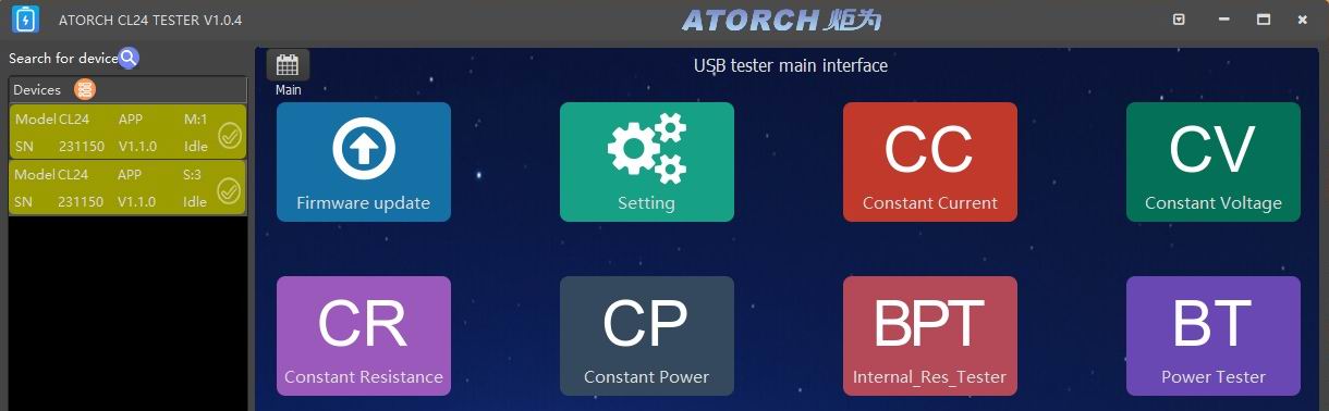
When you switch between the first and second load on the left, the values on the screen and the settings change accordingly.
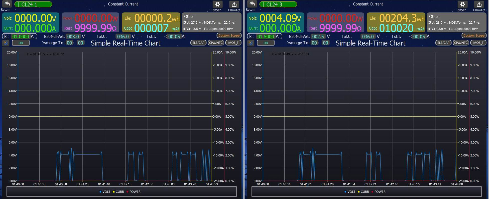
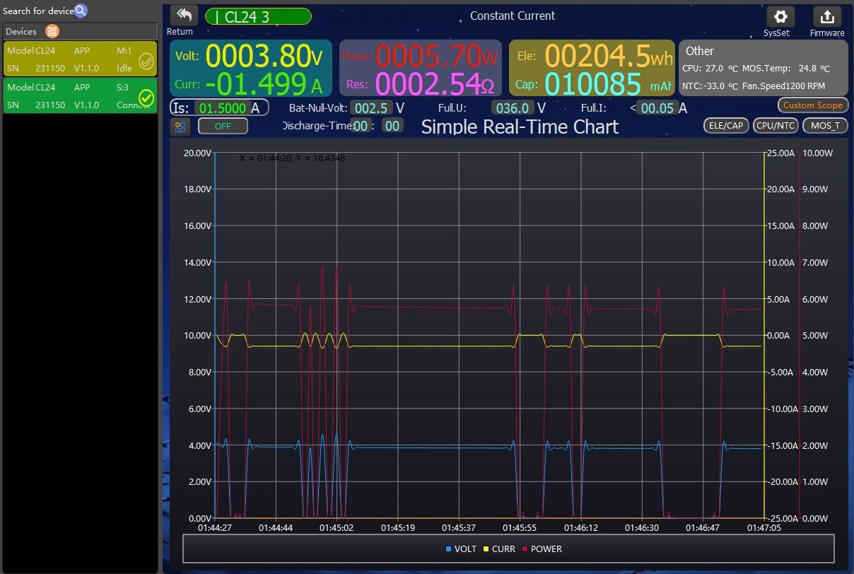
Something about the display had been bothering me from the start, and for a long time I couldn’t figure out what was wrong. It all became clear when I tried running one load while the other was idle, switching between them as I did so.
The values at the top of the screen changed correctly, but the graph was a complete mess....
The developers, without giving it much thought, simply plotted the results from both devices on a single graph—literally. While one load is selected, its graph is drawn; switch to the other, and its graph starts drawing on the same screen.
Here’s an example: one load is discharging a battery at 1.5 A while the other is idle, and I’m switching between them. The graph shows the results from both loads, but in a completely chaotic way.
This isn’t just a mess, it’s an absolute disaster. Each load’s graph should be displayed separately, not overlaid on top of the other. Developers, what on earth are you smoking over there?
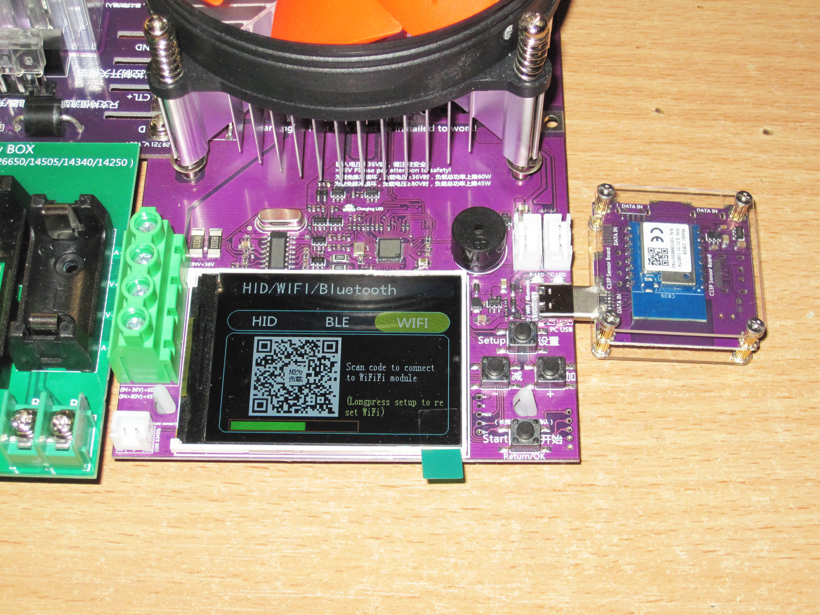
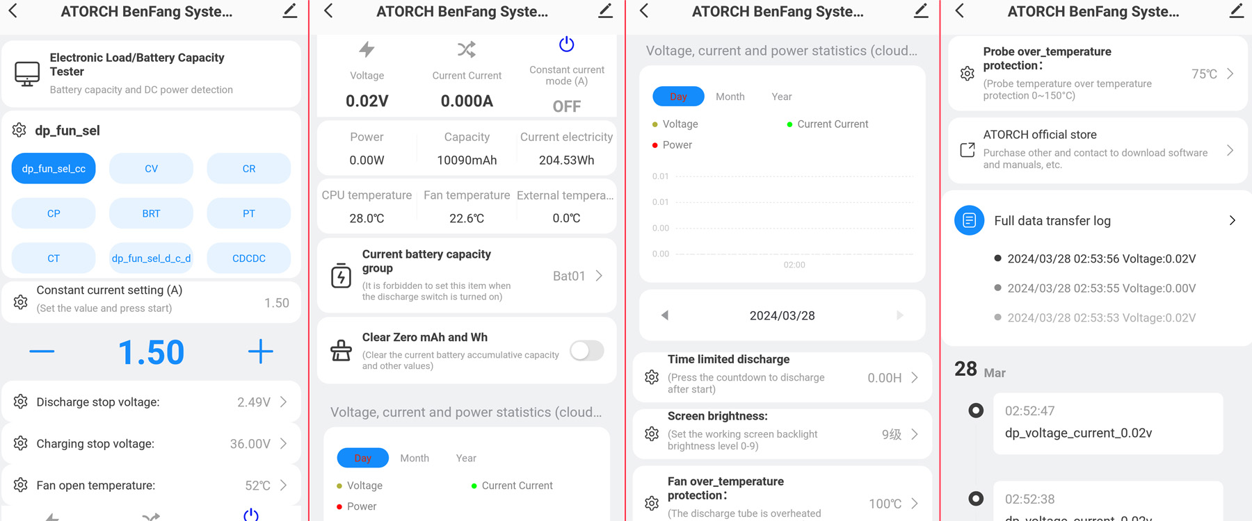
WiFi turned out to be incredibly simple and convenient.
Connect the module, open Settings, select WiFi, and exit Settings. The QR code takes you to the Smart Life app download page. If you already have the app, you don't need the QR code.
As soon as I launched the app, I was prompted to connect a new device. I agreed; the network was already configured. The app then started the connection process, and everything was done in about 20–30 seconds. There was very little to do manually; it was all automatic.

In the end, I got access to all the settings, just like with the 24EW. My criticism is the same as for the 24EW: the interface is awkward, with literally everything crammed onto one screen. Some rarely used settings could have been moved to a separate window.
There’s nothing else to describe; it was all covered in the 24EW review. It works, and that’s good.
Conclusions.
Well, I don't even know where to start. Let's begin with the good stuff—there is some, after all.
1. I liked the accuracy at low currents; it's clearly better than in previous versions.
2. The control menu and display have been redesigned, and the improvements are noticeable.
3. New features have been added, such as repeated testing and setting a pause between tests. Overall, it's noticeably more convenient to use.
4. Flexible connectivity: use USB, Bluetooth, or Wi-Fi, as you prefer. The previous versions have had some issues here: the old one has Bluetooth or USB, but it's outdated; the 24MP only has Bluetooth; the 24EW has Wi-Fi and USB, but no Bluetooth. It's a bit of a mess—in this version, you can choose what works for you.
5. Fan speed control, and the fan itself is fairly quiet. Nice.
6. They've switched to Type-C. If only it could also draw power from a QC charger and have the load request 12 V, that would be fantastic.
7. You can now work with multiple devices from a single piece of software.
8. The software itself has improved substantially. Compared with the old version, it's like night and day.
9. A low-current battery testing function is listed. I came across it in the description, but never figured out how to use it.
10. Something else, but I can't remember what.
But there are drawbacks, too.
1. You can't get more than 150 W of power, and above 36 V the limit drops to 60 W, or 45 W at 80 V. Modifying the power stage won't help; the load simply refuses to operate at those settings. I want at least 1000 W and at least 30 A, like the DL24!!!
2. The circuit design is partly the same as the DL24's: a relatively high-resistance shunt and a protection diode on the board. It's adequate for this design, but at 25 A the shunt will dissipate more than 3 W, while the two resistors are rated at just 1 W each. For example, when I build loads, I always replace the shunts with higher-power ones.
3. The charging control board. This is just ridiculous: putting a diode in series is a solution not even a schoolchild would come up with—it's idiotic. It immediately limits the maximum current and introduces a huge error. They'd have been better off leaving it alone. By the way, both the new and old boards switch the negative side with a transistor. Why? Why switch the negative side? The transistor is driven by a galvanically isolated converter, so it can go on either side, but they put it on the negative side. Good practice is to leave ground alone: don't switch it, and avoid putting shunts in it if possible...
4. Fan monitoring: we can see the speed, so why not add stall detection?
5. Controls and display. How many times do we have to go over this? You already have versions with an encoder, so why not put one here? And the display could be detachable—that would be much more convenient. Though in this particular case, mounting it on the board might be simpler, since the power is low anyway and few people will build the load into an enclosure. Fine, keep the display, but could you bring back button controls?
6. Why did they go back to a single transistor? They could have made the power stage like the one in the 24MP or 24EW; those have at least four transistors, and they operate under less stress.
7. I think there was something else; I'll add it later.
So, we have a rather mixed device. There are definite improvements, no question, but there are also regressions, as well as a return to the very first generation of this product line. In my opinion, this load would be very well suited to testing single-cell or 2S batteries. With the expanded charging controls, it would make an even better battery tester—but the charging control board definitely needs further work.
By the way, a question: I probably won't keep these for myself, but if anyone wants one, I can build a couple of loads based on them in enclosures, with a proper charging control board, reverse-polarity protection, and support for an external charger. In short, I can make a battery tester the way I envision it, as a complete, finished device.
That's all for today. I hope this was useful, and as always, I'd be very glad to hear your comments.
$40.91
This page was found when searching for:
atorch cl24r обзор, 1, варианты использования электронной нагрузки cl 24r, https://www.kirich.blog/obzory/izmeritelnoe/1231-elektronnaya-nagruzka-cl24-chto-ty-takoe, cl 24, cl24w manual
atorch cl24r обзор, 1, варианты использования электронной нагрузки cl 24r, https://www.kirich.blog/obzory/izmeritelnoe/1231-elektronnaya-nagruzka-cl24-chto-ty-takoe, cl 24, cl24w manual
The figures from this review are in the measurement database: Electronic loads
Calculate manuallyAll calculators
Discounted products
You may be interested in


Discounted products
Support the project
All the content on the site and the advice are free, but we’d be grateful for your support of the project and the channel!
Comments2
Discuss on the forumHave a question or some experience to share? Discuss the article with the author and readers: the forum is a convenient place to share schematics and photos.
Go to the forumOnly registered readers can comment. It takes a minute to sign up, and you can log in with the same account you use on the forum.
Log inRegister
Comments are published in their original language.