
Fnirsi LC1020E LCR Meter
$52.54
A reminder: to keep up with new posts on the blog, I recommend following me on Instagram. I'll post notifications about new articles there and might also share something interesting now and then - link to my account
You can also subscribe to updates and new articles on the Telegram channel - https://t.me/KirichBlog Just a note: discussion of reviews and articles is enabled on the channel, and you can also just chat. I recommend it.
For those who haven't seen it yet, I was referring above to the XJW01 LCR meter. There's also an article about installing it in an enclosure.
It's an interesting little instrument, though somewhat outdated: it doesn't have many modes, the test frequency only goes up to 7.8 kHz, and it's quite large.
Basically, curiosity was the main reason I agreed to review Fnirsi's version.
I can't say I'm a fan of this company. There are plenty of complaints: their products often have “teething problems” even in production models, and their product support isn't great. On the other hand, I work with design and manufacturing, so if there's something you don't like about their products, I can say this: try designing a device yourself—and, even harder, take it all the way to mass production and then make your name known around the world. I'd be curious to see how you do.
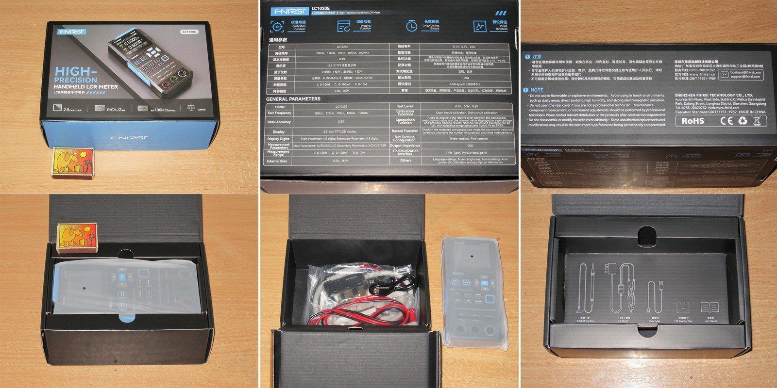
I have no complaints about the packaging at all: it's neat, attractive, and even thoughtfully designed. The only thing that took away from the impression a little was that everything included was just tossed together, albeit in bags. Still, it's nice that the bottom of the inner compartment has pictures and labels showing what's what. Handy.
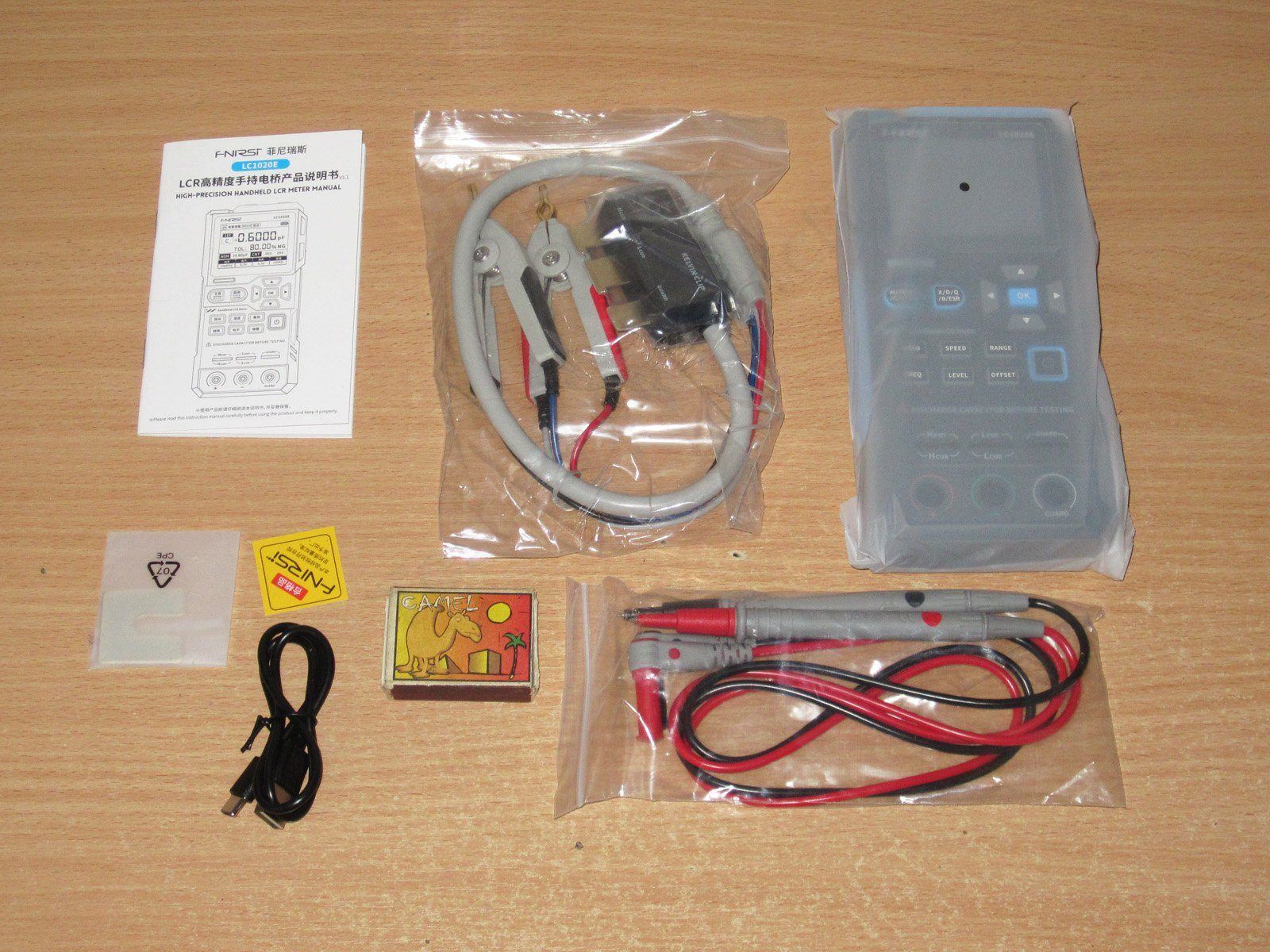
Here's the full kit. I'd say it has everything you need, although I remember my old meter also came with tweezers, which I occasionally used—even though the measurement accuracy with them was, of course, a bit worse.
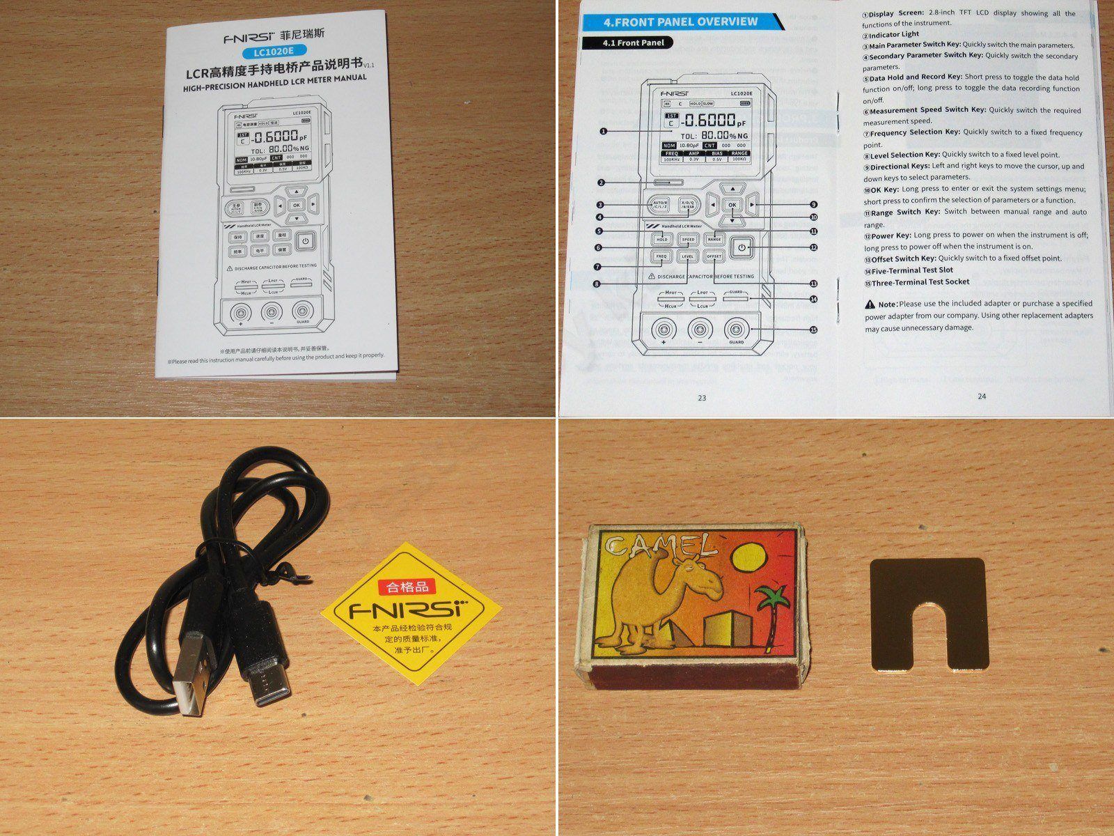
The manual is in English and includes pictures, but that doesn't really matter, since the target audience should generally know at least basic technical English. I did notice, though, that the display shown in the manual looks quite different from the actual display.
Cable for connecting to a PC or charging the built-in battery.
Jumper for calibrating the instrument.
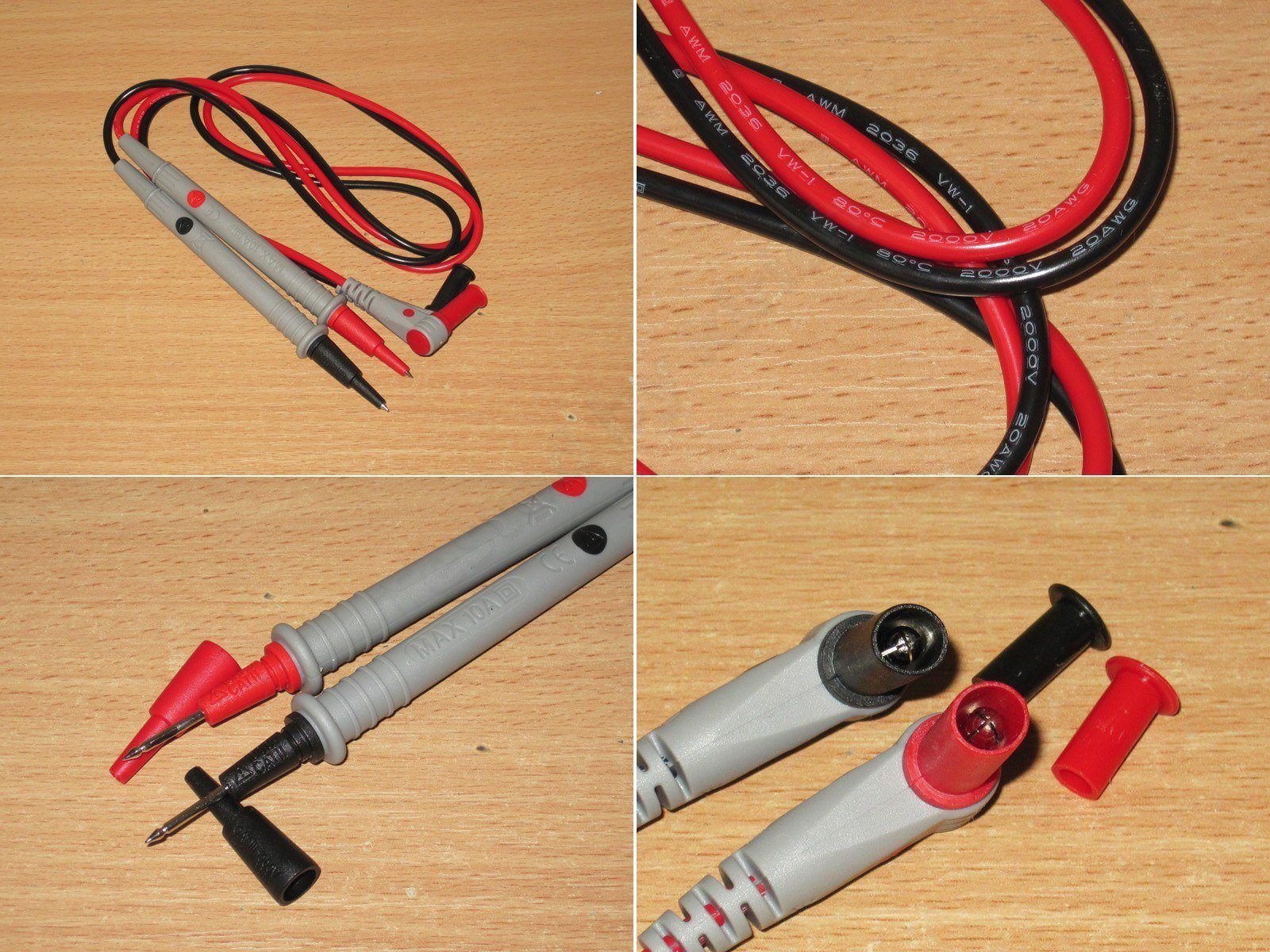
The included test leads are essentially a budget alternative to the tweezers for the XJW01, although that meter also has a four-wire connection before you even get to the tweezers.
These are really basic test leads. The wires are marked 20 AWG, which is about 0.5 mm². They're rated for 10 A, but in my view that's really only the maximum current for short bursts. On the other hand, the small wire gauge here can increase measurement error.
At first, the plugs looked like they were different diameters, but no—they just looked that way.
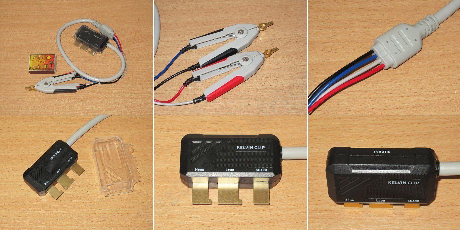
Now these are much more useful: test leads with Kelvin clips. Subjectively, they seem well made. My only real complaint is the rather stiff cable, which makes them less convenient to use.
The part that connects to the instrument wasn't even sealed in plastic; it was wrapped in thick, clear heat-shrink tubing. There are markings showing how to insert it, though the principle is simple: the cable should point to the right, so the labels will be readable. The contact section is made from double-sided fiberglass PCB material, providing a four-wire connection plus a shield. When you pull this “plug” out of the socket, the contacts switch to two-wire mode.
The pin section that plugs into the instrument has small protrusions to prevent it from coming loose accidentally. Insert it, slide it to the right, and that's it—it won't fall out on its own. To remove it, slide it to the left and pull it out.
The instrument is fairly compact, basically the size of a typical multimeter. It has a black case with blue accents, in the style of the company's other devices.
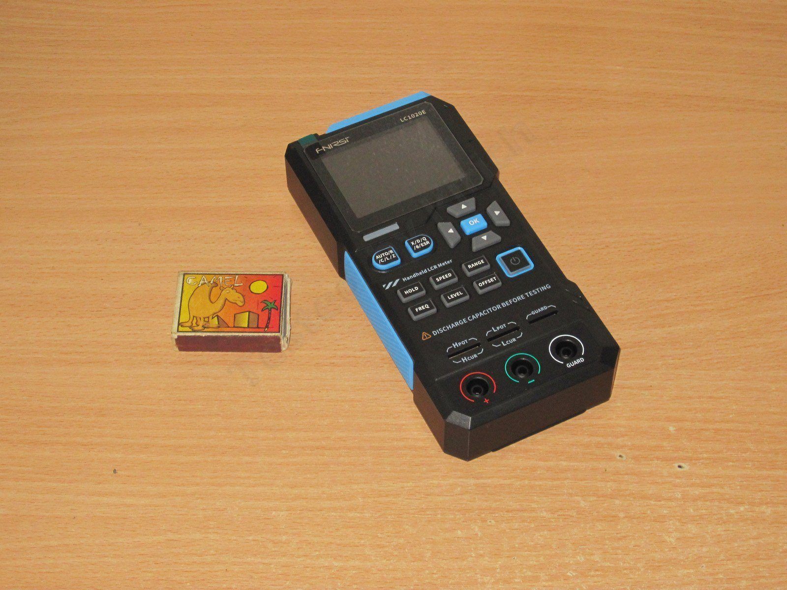
From the outside, it looks like a brick: just a plastic block with colored inserts.
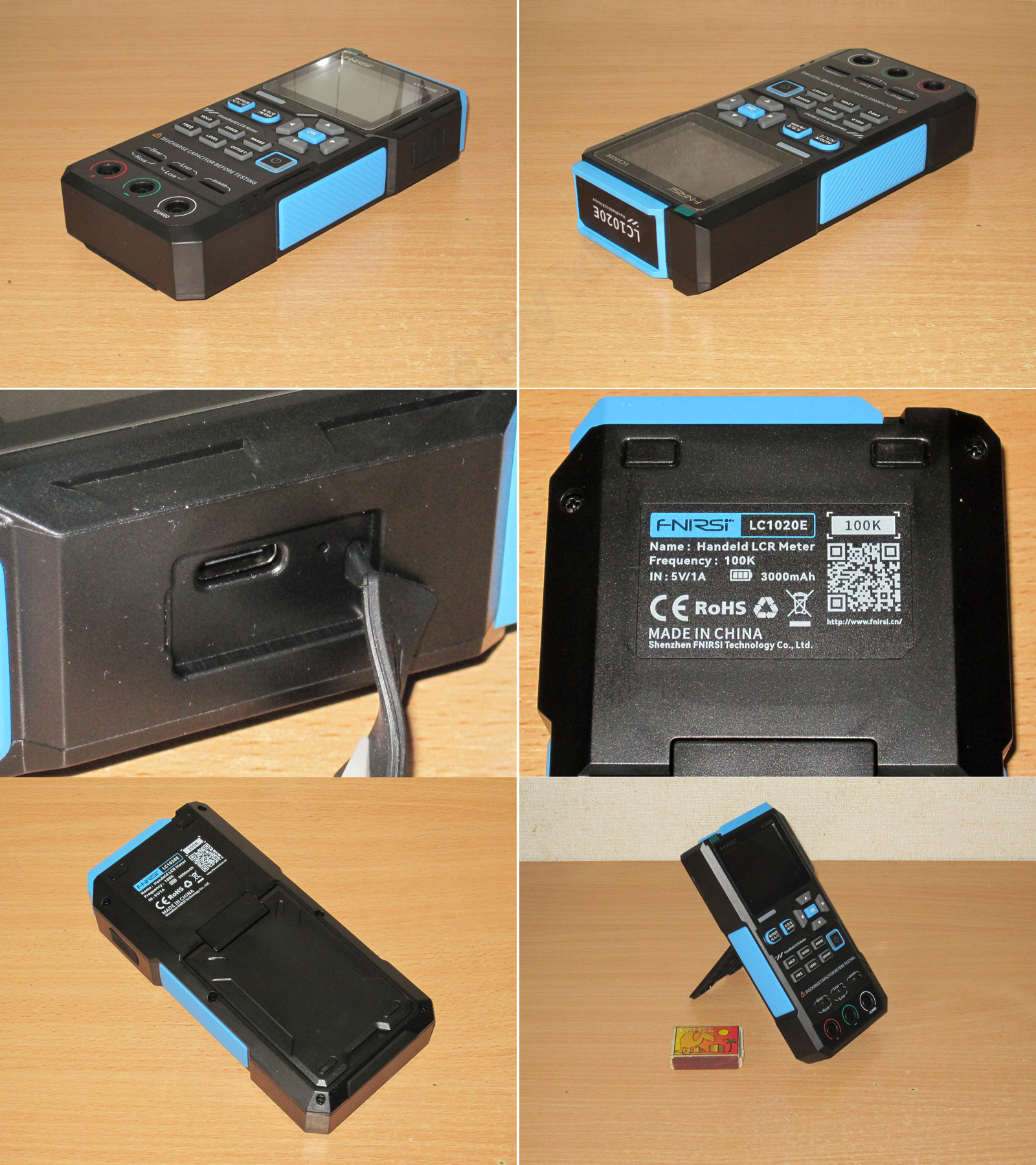
There's a USB port on the right, covered by a rubber flap. There are no other ports on the sides.
There's a label on the bottom showing the battery capacity and, for some reason, a frequency of 100 kHz.
There's also a fake set of feet on the bottom, along with a stand for positioning the instrument vertically. I don't have any particular complaints about the stand, but not having proper rubber feet is really inconvenient. Remember how I said above that the cable on the Kelvin test leads is very stiff—really rigid? Now combine that with plastic feet and a relatively lightweight instrument. Basically, when you're using it on a smooth table, it'll definitely slide around.
The battery is rated at 3000 mAh. I haven't measured its power consumption, but I've been using it for quite a while now and haven't had to charge it once, so I have no complaints there.
The information is displayed on a 2.8-inch screen. It comes with a protective film already applied, which is useful: even with careful use, you'll be dealing with little scratches, so at least there's some protection.
There's a sorting-mode LED indicator to the left of the display. It lights up a pleasant green.
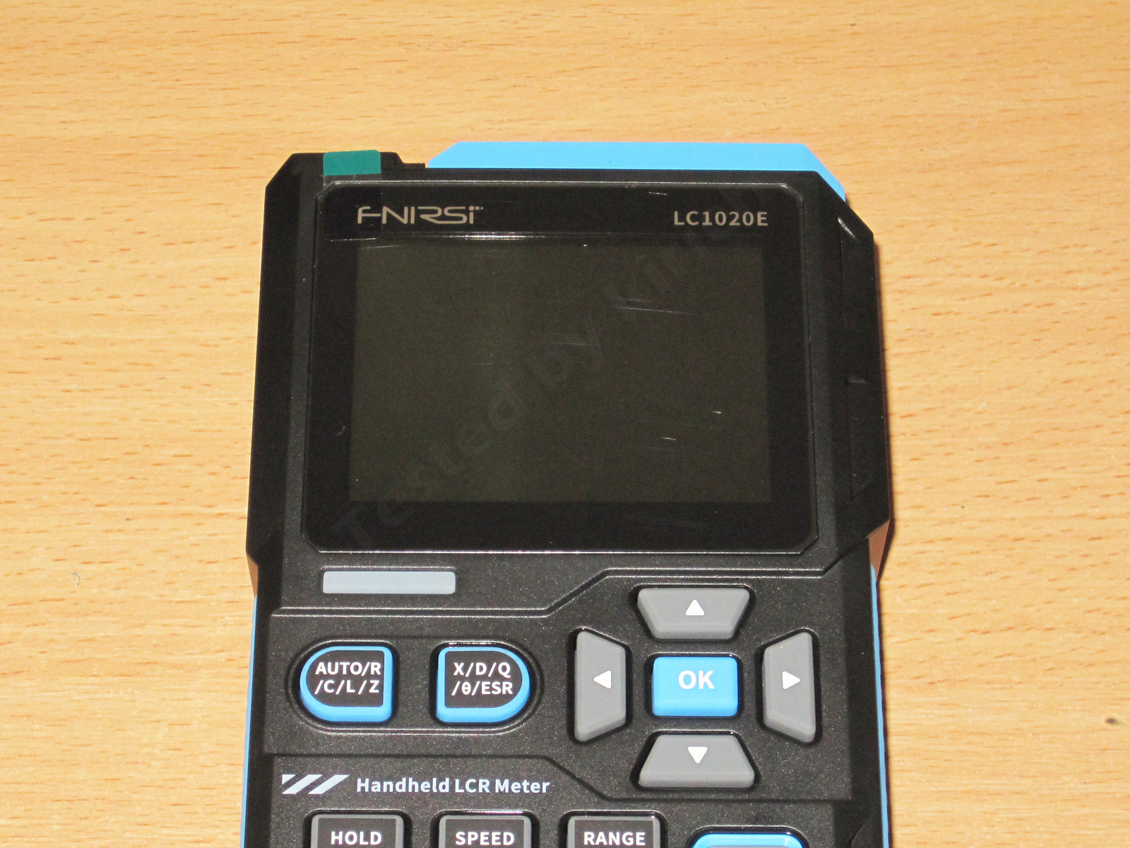
1. Controls
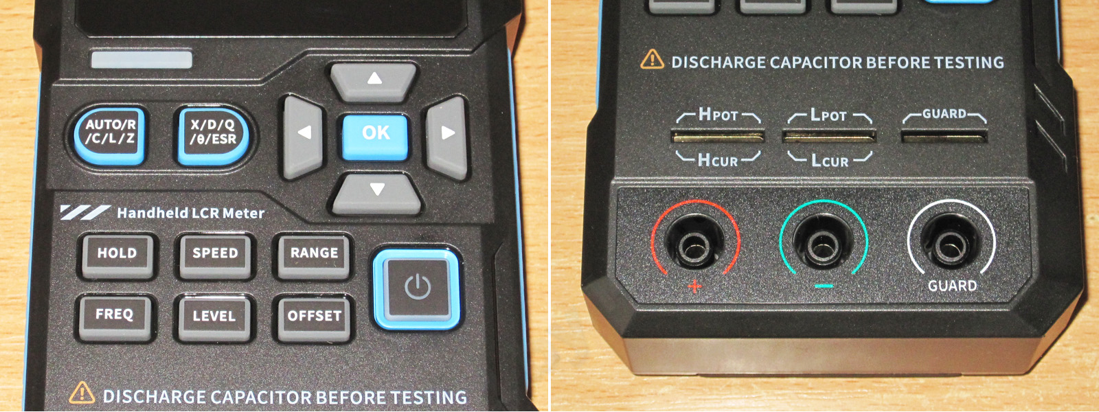
There are two buttons on the left. One selects the main measurement mode: Auto, Resistance, Capacitance, Inductance, or Impedance. The other selects the secondary parameter to display: Reactance (X), dissipation factor, quality factor, phase angle, or ESR.
To the right are the menu, navigation, and selection buttons.
Below is a group of six buttons: Hold, display speed, range (auto or manual), frequency, test voltage, and bias voltage.
And farther to the right is the power button.
2. Terminals
The terminals at the top are for direct component measurements or connecting Kelvin probes. In either case, the instrument uses a proper four-wire connection.
Below are three terminals for regular probes, but this is a two-wire setup. Measuring relatively large capacitance, inductance, or resistance shouldn't be a problem, but in my opinion the error will be much greater when measuring small values.
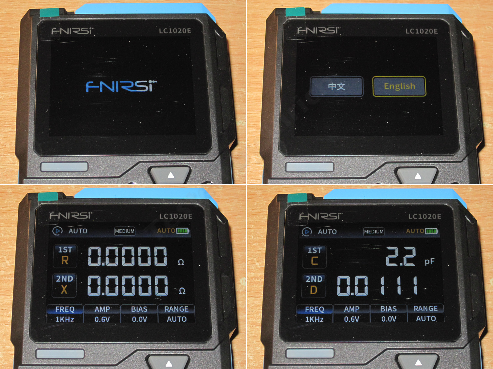
The first time you turn it on, you'll be asked to choose a language. Chinese is selected by default, so I recommend switching to English right away to save yourself from navigating the menus later.
Zeros briefly appear on both readouts, then the instrument enters its normal operating mode.
A few things to note. The instrument remembers its settings: the measurement mode, frequency, and so on. The only thing it doesn't remember, so you have to select it manually each time, is the secondary parameter. For example, I usually need ESR, which means pressing the button three more times. Annoying. I have no idea why they didn't make it remember all the settings, but that would have been much more convenient.
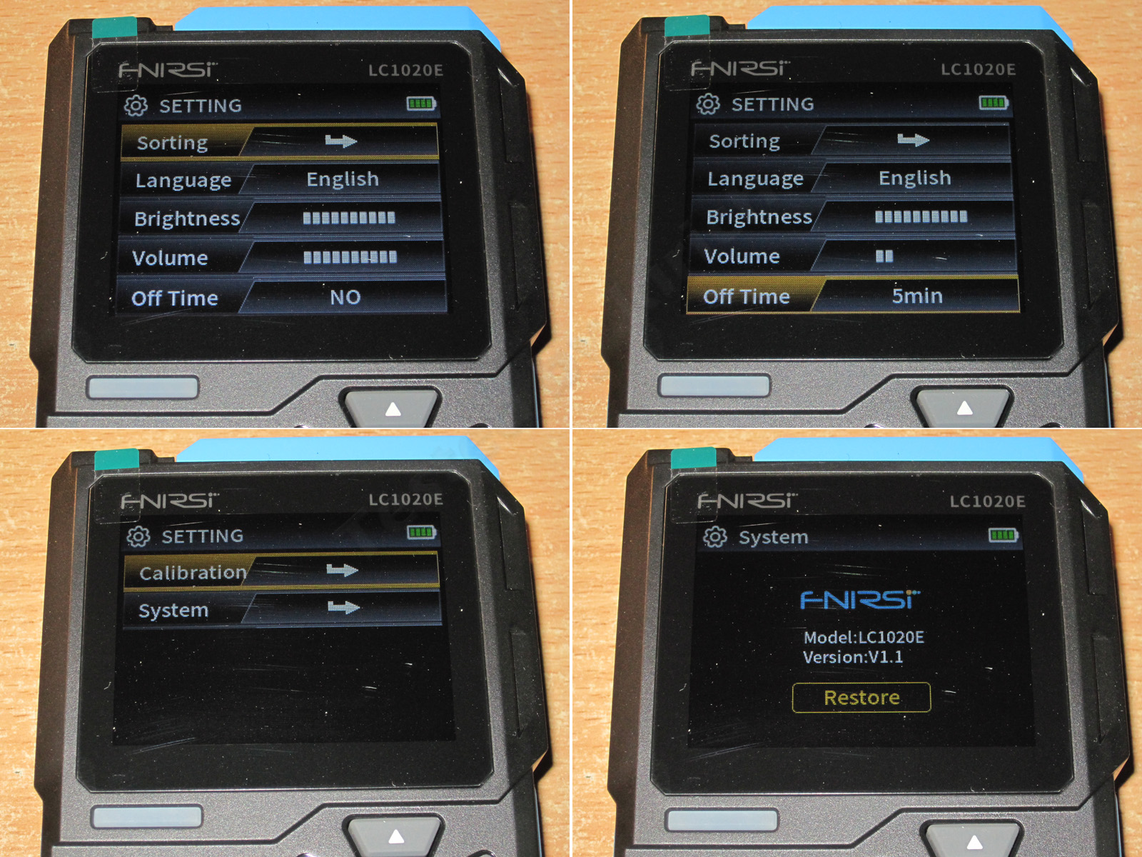
The menu is very simple. It includes:
1. Sorting mode.
2. Language
3. Display brightness
4. Built-in buzzer volume
5. Auto power-off
6. Calibration
7. Instrument information. Mine has firmware version 1.1; the manual shows screenshots from version 1.0.
I didn't quite understand the auto power-off setting. The thing is, it... doesn't work. I immediately set it to 5 minutes, but the instrument absolutely refuses to turn itself off. It doesn't seem to consume much power, and you can always recharge it, but still, this is a bit of a botched job.
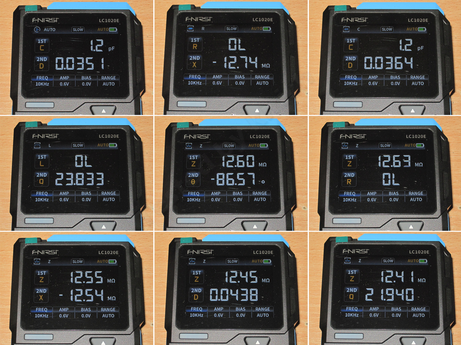
1–5. As I mentioned, there are four modes for displaying the main value: Auto, Resistance, Capacitance, Inductance, and Impedance. The upper-left button selects the mode.
6–9. The second button lets you choose which secondary parameter to display.
Basically, the instrument measures everything at once, and you choose what it displays. I'll say right away that, in my opinion, Auto is the least useful mode. I can't remember ever using it, either back then or now.
The buttons along the bottom let you select:
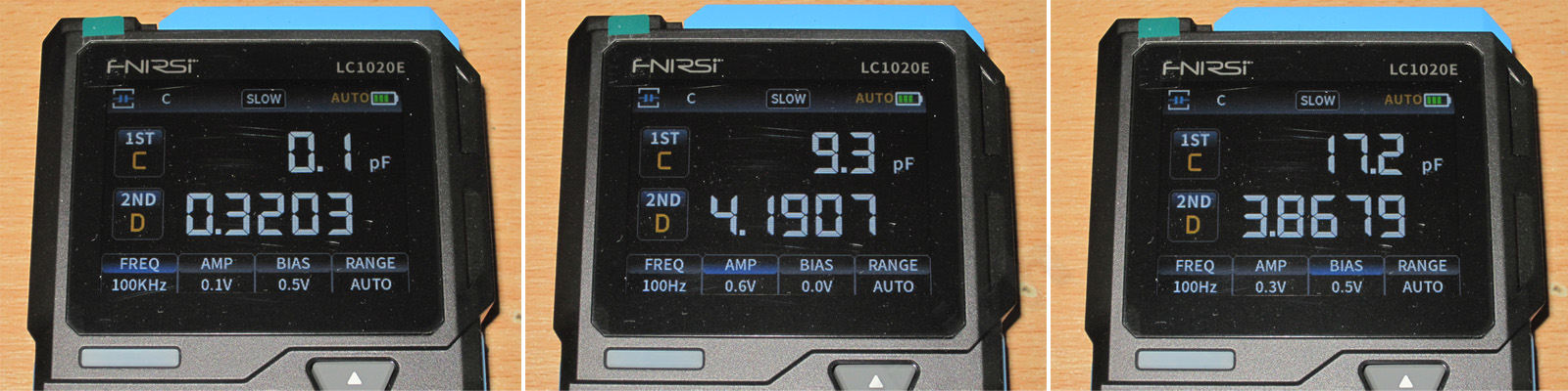
1. Test signal frequency: 100, 120 Hz, and 1, 10, or 100 kHz.
2. Test signal amplitude: 0.1, 0.3, or 0.6 V
3. Bias voltage—or rather, whether it’s enabled—0.5 V, or disabled.
Note that with bias voltage enabled, the test signal can only be 0.1 or 0.3 V; you won’t be able to select the 0.6 V setting.
The measurement range is shown to the right, either auto or manual.
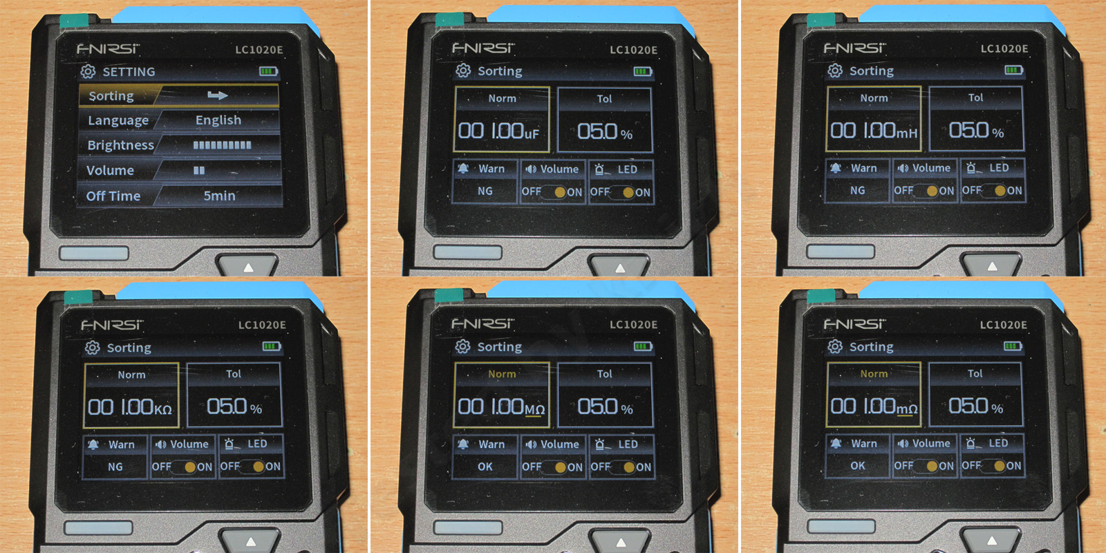
The sorting mode can be useful when selecting components. Here you can choose what to check—capacitance, resistance, or inductance—as well as the value, tolerance percentage, and response (whether to signal when a component is out of tolerance or within tolerance), with an audible or visual alert.
Testing showed that sorting mode works, but it takes a little getting used to. First, it’s a bit sluggish (the audible and visual alerts are what lag), but that’s actually fine. What’s less expected is that if you reconnect, say, a capacitor that’s within tolerance, the meter may not alert you, even though it displays the result and logs it.
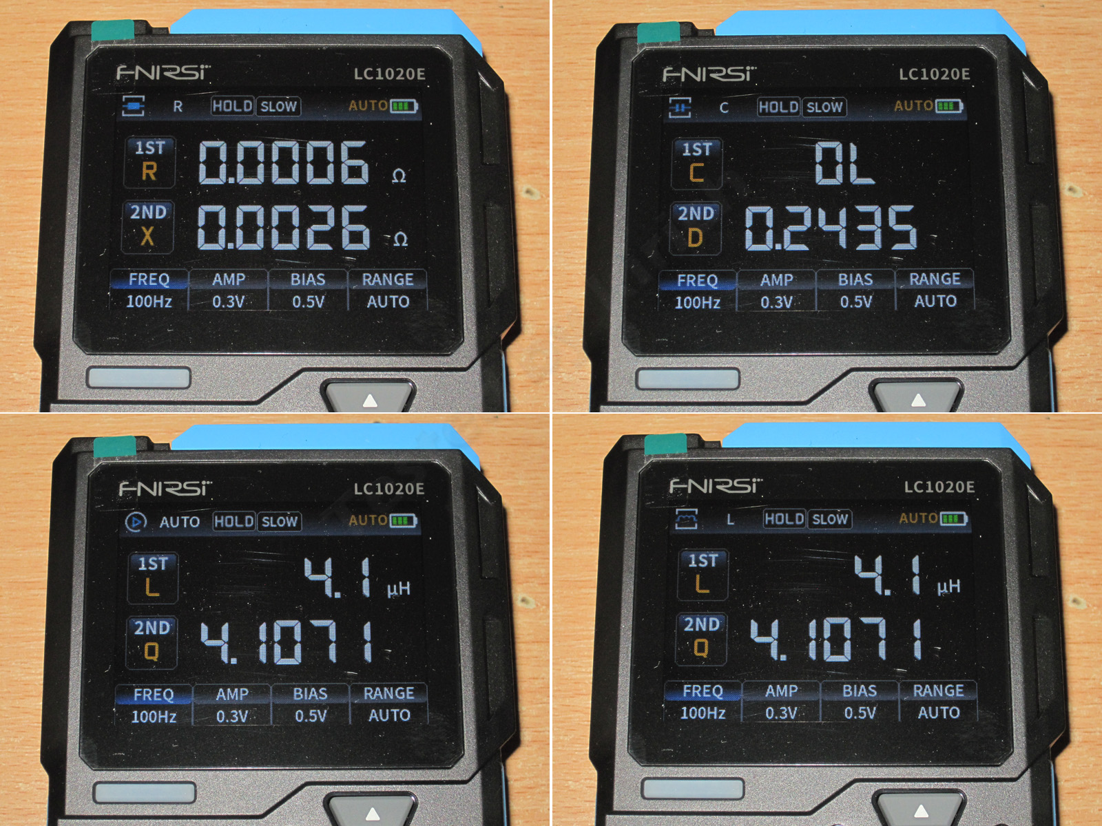
The hold mode is nothing unusual. The only thing worth noting is that the meter does indeed measure everything at once and then freezes the readings, since switching the primary measurements doesn’t affect the secondary readings.
You can also see the display update speed at the top: slow, medium, and fast. I use slow so the values don’t flicker in front of my eyes.
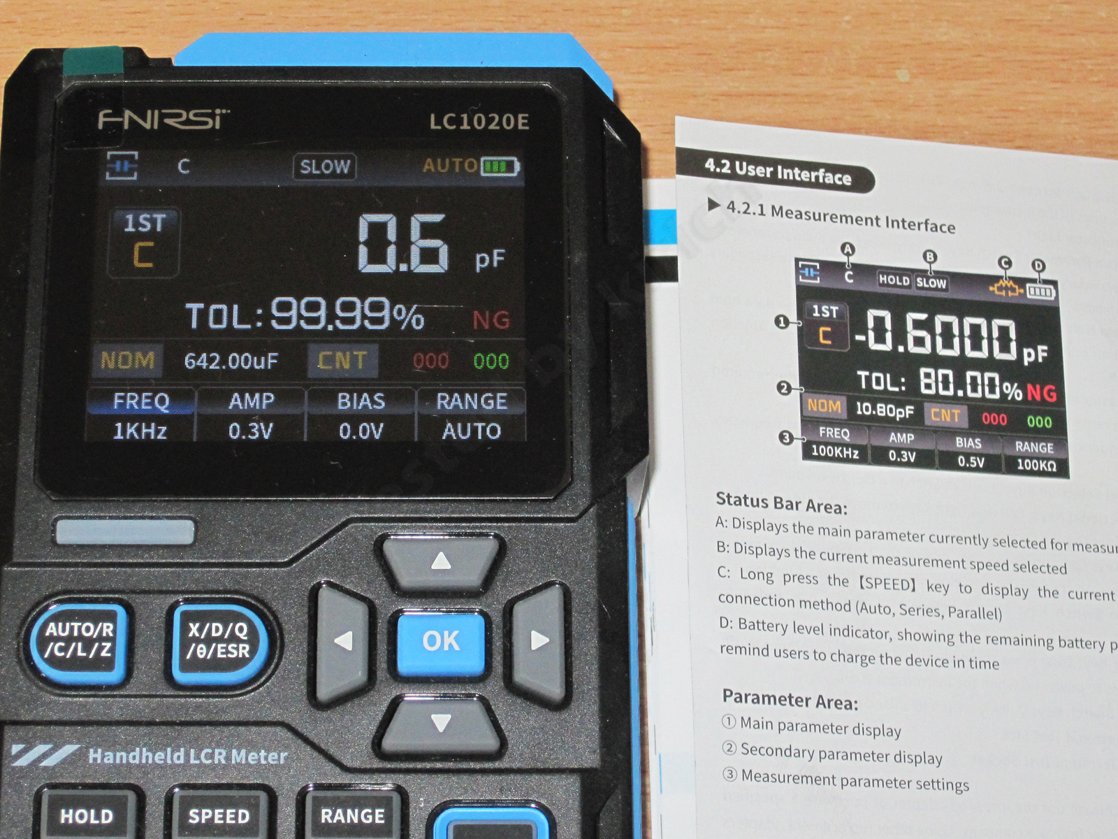
It took me a long time to figure out how to enter sorting mode. You can set the parameters, but how to actually make it work isn’t clear.
It turns out this feature is in the logger mode, which you access by holding down the Hold button. That’s not intuitive at all, in my opinion.
Menu and control design is a very subtle thing. Ideally, instruments at this level should be designed so users never have to consult the manual. Of course, instruments with a huge number of complex functions, involving math, modes, and so on, are harder to use without a manual—but this one...
But never mind. Hold down the Hold button to enter this mode. In some ways it’s simpler, and in others more complicated. It doesn’t show the additional measurements, only the main ones: capacitance, inductance, and resistance. But it does show:
the accuracy percentage (relative to the value set in the sorting menu)
a pass/fail indicator
the nominal value set in the sorting menu, against which the deviation percentage is calculated
a counter for failed and passed components, which resets when the meter is restarted
The mode menu is below; it’s the same as in the main mode.
The basic idea is simple: for example, set up a capacitor test, enter the capacitor’s value—in my case, 642 µF—and set the tolerance, say 5%. Then switch to this mode. Now test the capacitors one by one. If one is within tolerance, you get an alert (on the display, via the LED indicator, and the buzzer), and the pass/fail counter increments by one. Test the next one, and the process repeats.
You can choose what to measure: capacitance, inductance, or resistance. But there’s a catch: in sorting mode, I set it to measure capacitance, with a value of 642 µF and a tolerance of 5%. But if I switch the component type from this additional screen, I get 642 µF, 642 kΩ, or 642 µH :)
Overall, I find this mode not only unintuitive, but also rather inconvenient.
But that’s not even the main issue. This mode is an auxiliary one, and when you restart the meter, it automatically returns to the standard mode shown above. Yet the manual only shows this display mode.
Fnirsi, how did you manage to write a manual that shows only the display for an auxiliary mode, which not only leaves out some measurements but is also the default mode? How did that happen?
There’s also a mode for selecting the equivalent circuit, series or parallel, accessed by holding down the Speed button.
I’ve never really bothered with it; the automatic mode is more than enough for me.
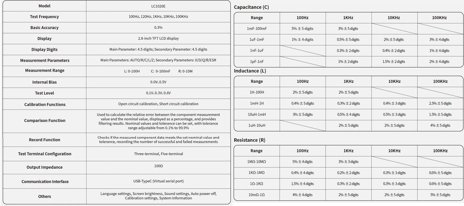
Before getting into the tests, here’s the manufacturer’s table. It gives you an idea of the claimed measurement error and how the measured values depend on the measurement frequency.
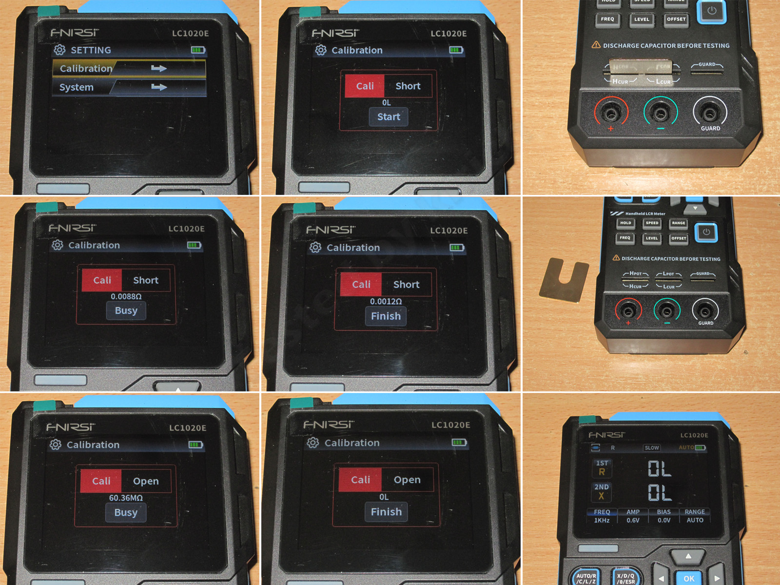
Before starting the test, I calibrated the meter. It’s very straightforward.
Go to Settings, then Calibration, install the jumper, and start the Short calibration. Wait about 30–40 seconds, then select Open, remove the jumper, and start the calibration again. Wait once more, and that’s it—you’re done and ready to use the meter.
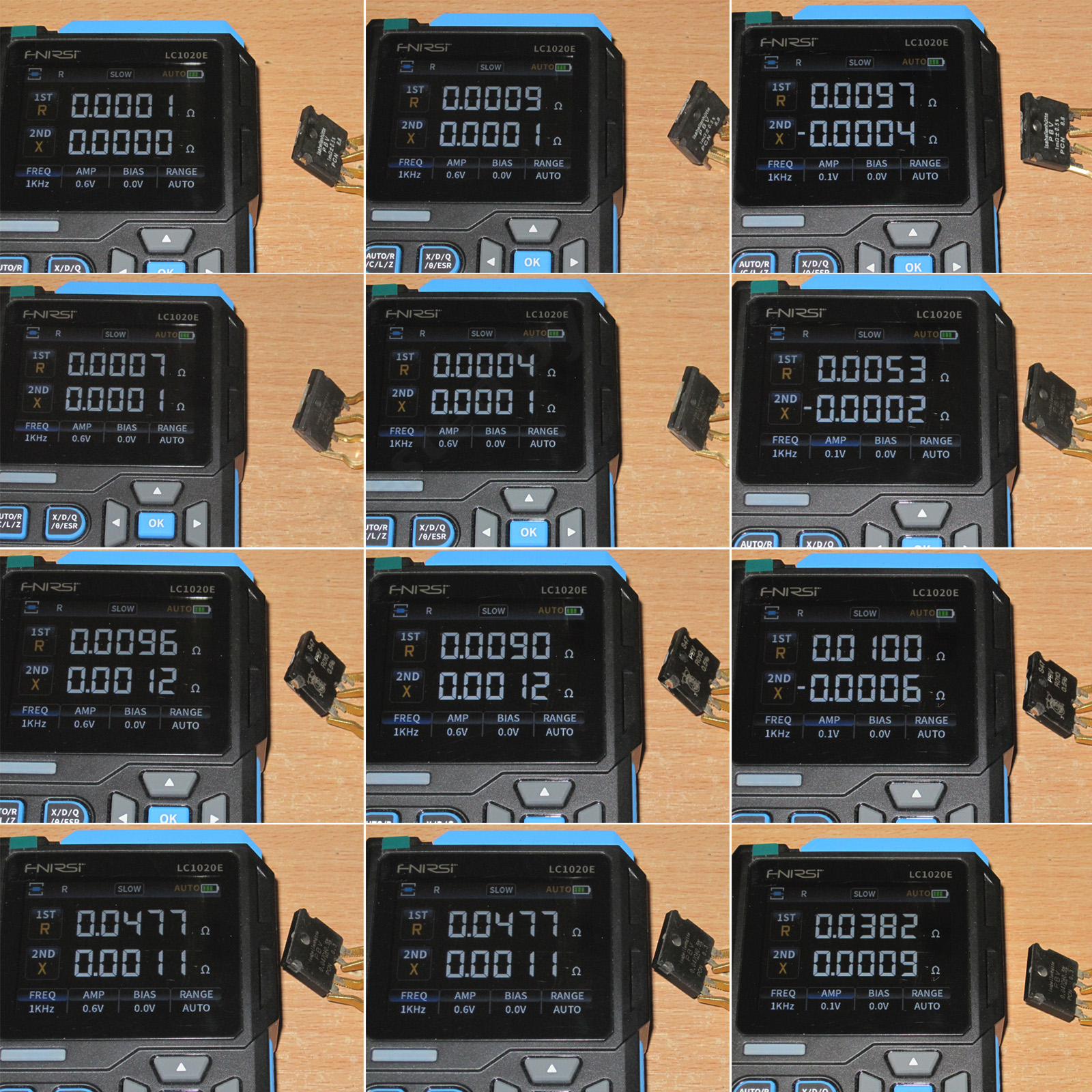
For my work, measuring low resistance is the most critical. Ideally, I’d need to measure down to at least 0.5 mΩ, but the lowest value I have at home is 1 mΩ.
So I picked four four-terminal shunts: 1, 2.2, 10, and 47 mΩ. They’re branded, with a stated accuracy of 0.5%.
And here you’ve probably noticed the letter C on the Kelvin clips. Let me explain. The probes have what you might call power and measurement contacts, and these shunts do too. For accurate measurements, connect them correctly: the “power” leads to the outer terminals and the measurement leads to the inner ones. Obviously, this only applies to four-terminal shunts.
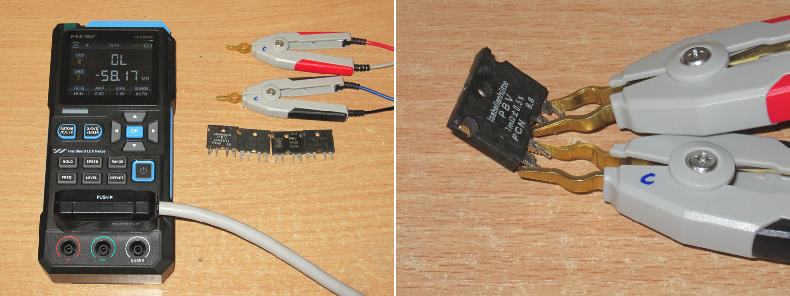
And here I was in for a major disappointment. Sure, the specs say the range starts at 1 mΩ, no argument there, but I was hoping for at least this much.
So, here’s what we get:
1 mΩ: the readings are all over the place, jumping from zero to the actual value. Change the test voltage and it might show 10 mΩ instead of 1.
2.2 mΩ: I wouldn’t say it’s much better. At 0.6 V it reads low, at 0.1 V it reads high. But worse than that, the readings simply won’t settle down. Basically, it’s the same mess. Just forget about measuring values this low; it’s not happening.
10 mΩ: at least the meter starts to behave somewhat normally here, although, to be fair, the readings still jumped around, so I don’t really trust them.
47 mΩ: at 0.6 V it was fine, with the readings almost rock steady. But select 0.1 V and it shows some nonsense. Maybe it would have settled down eventually, but that’s not measurement...
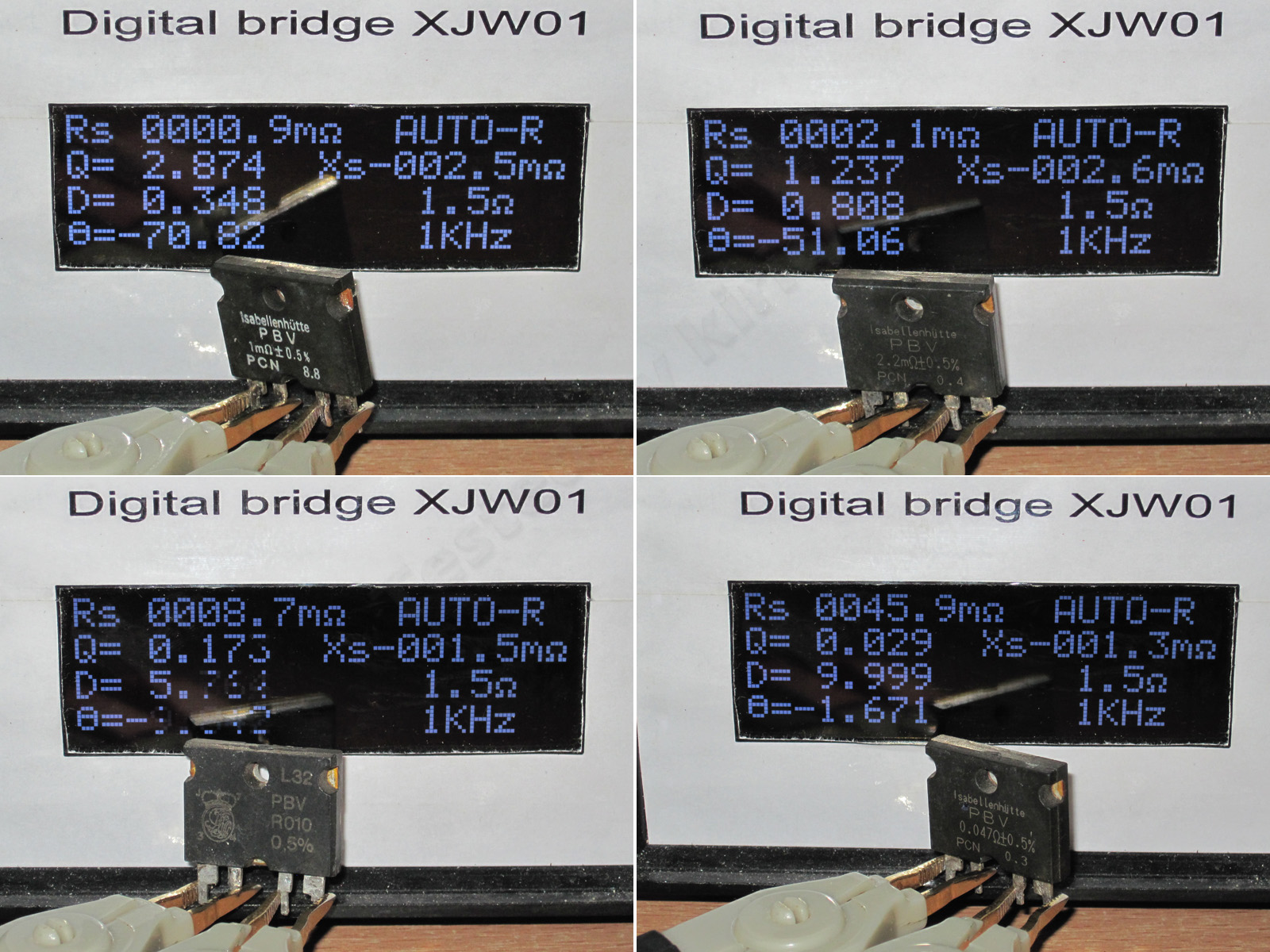
At this point I wondered if I was doing something wrong, so I got out my old meter and checked with that. I should mention that I didn’t spend much time calibrating it back then, and I did that many years ago.
But in any case, first, the readings are much closer to the actual values, and second, they fluctuate by no more than ±1 count, and even that rarely.
And yes, mine needs calibrating too. As I recall, when I did it back then, there was a catch: I could get it more accurate around 1 mΩ or at 10 and above, but not both. I calibrated it mainly for very low resistances.
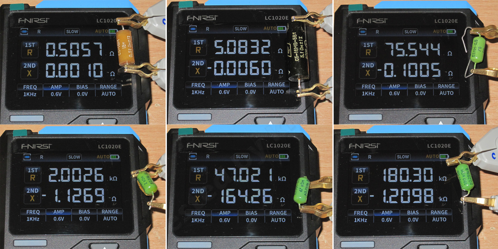
I tested a few more wirewound resistors, with tolerances from 0.25% to 1%: 0.51, 5.1, and 75 Ω, plus 2.2, 27, and 180 kΩ.
Everything is fine here, although I think it would be pretty hard to mess this up.
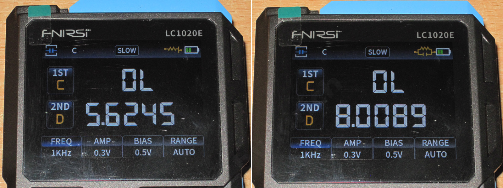
In practice, the meter can measure down to about 10 mΩ, but there are some caveats regarding the test voltage. For some reason, the 47 mΩ resistor behaved strangely at 0.1 V. When measuring the 5.1 Ω resistor, I tried changing the frequency and test voltage. There was a difference, but it was barely noticeable.
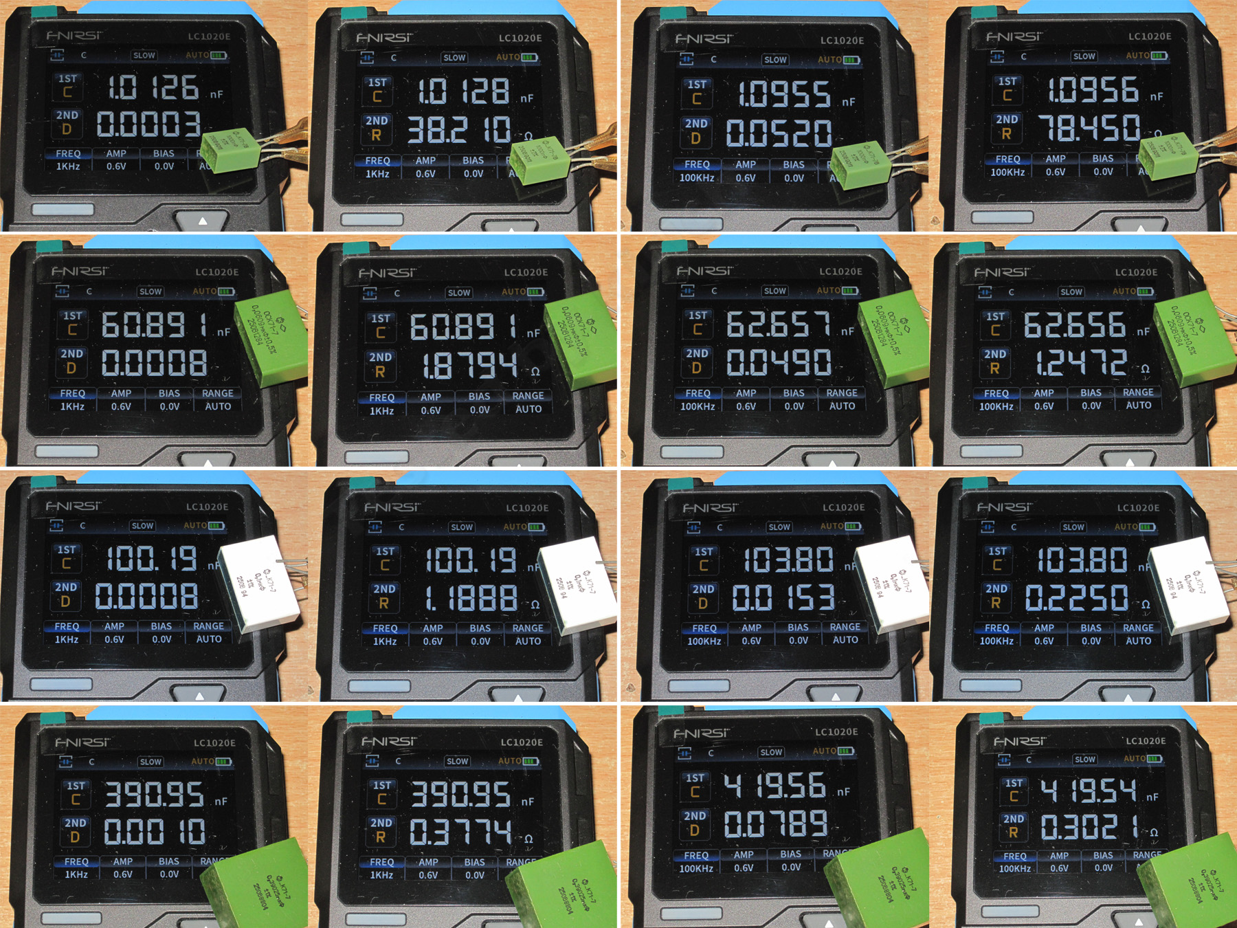
The next step was to check capacitance measurements. To start with, I took four capacitors: a 1000 pF one, and 0.0609, 0.1, and 0.3902 µF ones, all with 1% tolerance.
Then I measured capacitance, dissipation factor, and ESR at 1 and 100 kHz.
It does measure them, in principle, although the ESR reading for the 1000 pF capacitor jumped from 1.5 to about 40 Ω. As I mentioned earlier, the meter’s readings can be unstable, which is genuinely annoying. Even slow mode doesn’t help, let alone medium and fast modes, which I don’t see any point in using at all.
Polarized capacitors—or, more precisely, higher-capacitance capacitors—turned out to be a little more complicated.
The specs say you can measure up to 1000 µF at frequencies of 10 and 100 kHz.
But it turns out I can’t even measure 47 µF at 100 kHz; the highest frequency I can use is 10 kHz.
And when I try to measure 680 and 1000 µF at 10 kHz, I get complete nonsense.
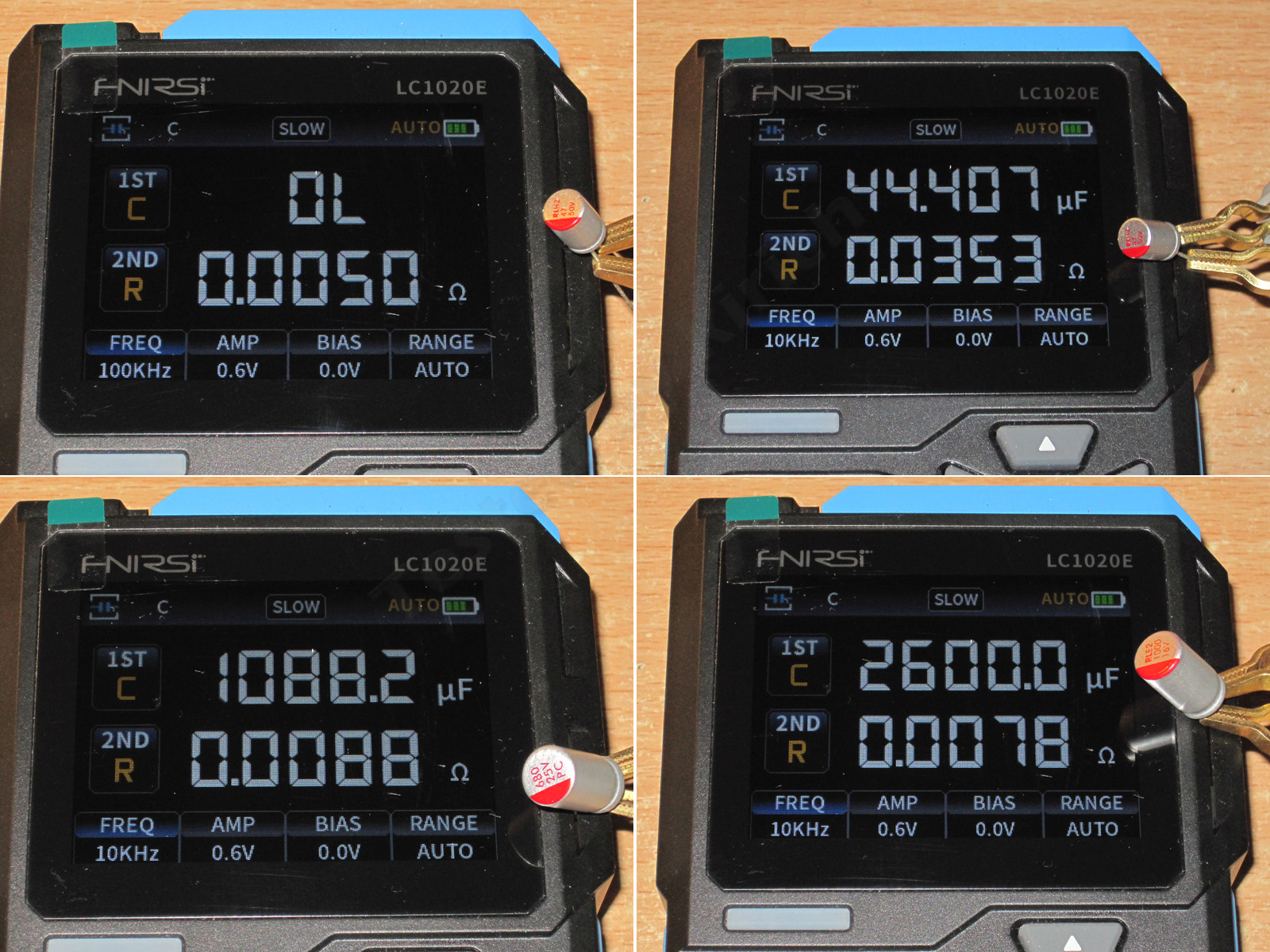
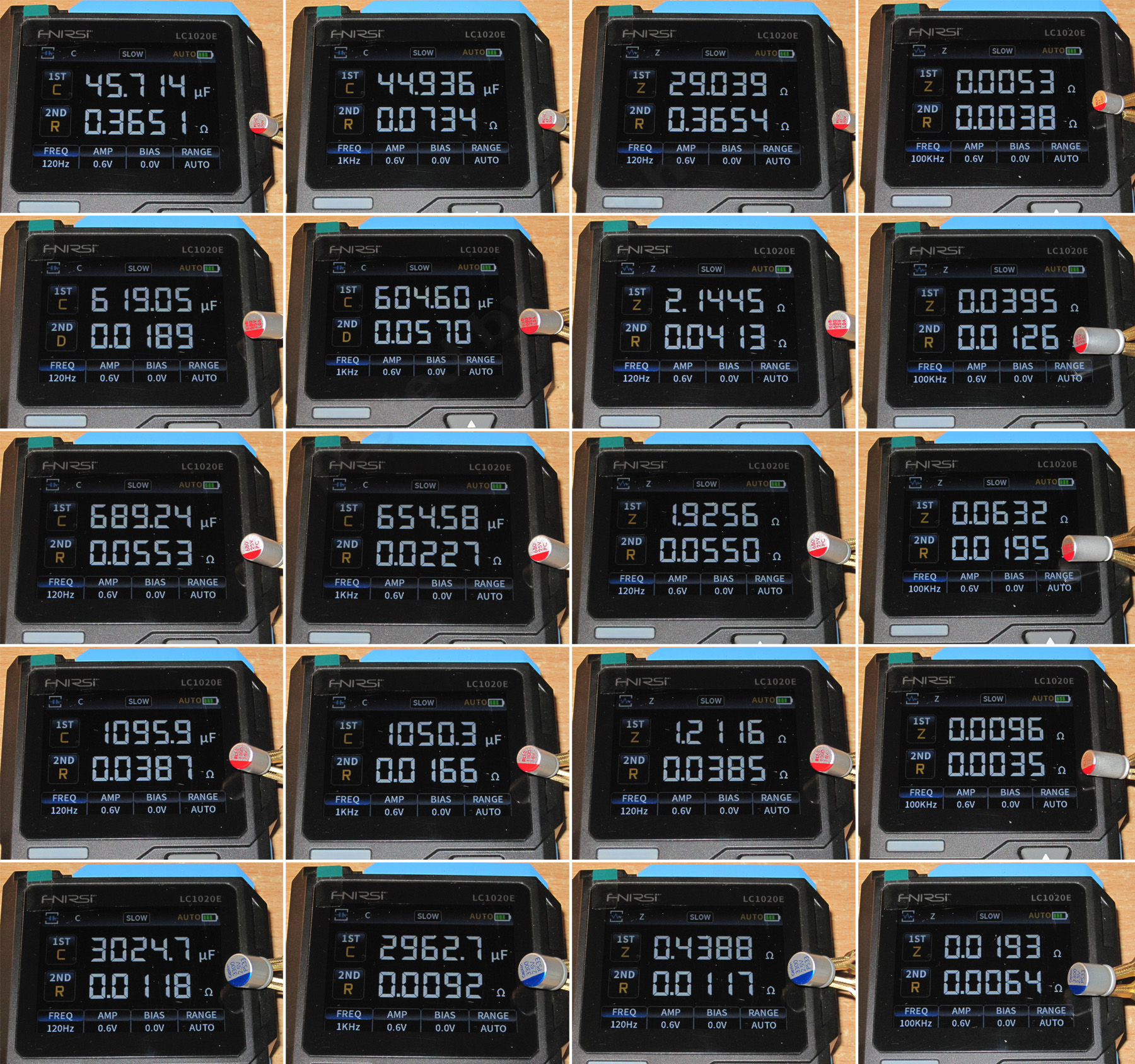
Next, I simply measured the capacitance and impedance of various capacitors. First, polymer types:
47 µF 50 V, 680 µF 25 V (two types, although they were bought in the same lot), 1000 µF 16 V, and 3300 µF 2.5 V.
The photo shows capacitance and ESR measurements at 120 and 1000 Hz, as well as impedance measurements at 120 Hz and 100 kHz.
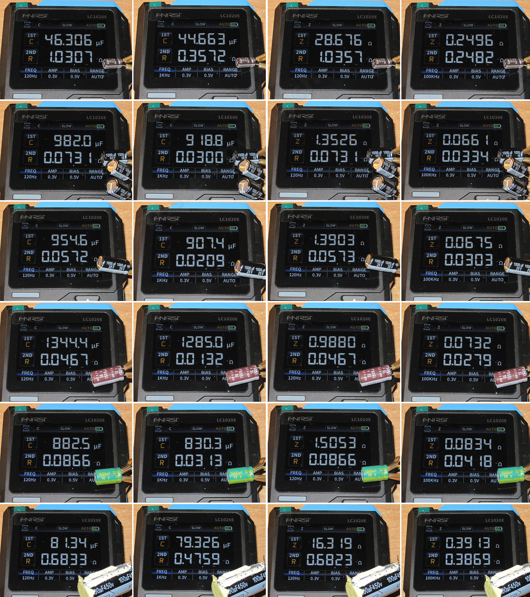
And regular electrolytic capacitors: 47 µF 35 V (Samwha WL), 1000 µF 16 and 25 V (I think Panasonic), a used 1500 µF 16 V, some Chinese 1000 µF 16 V, and a used 100 µF 450 V.
Measurements were taken in the same modes: capacitance at 120 Hz and 1 kHz, and impedance at 120 Hz and 100 kHz. There was one difference: since these capacitors have liquid electrolyte, I enabled the offset, which is needed for polarization. The same is required for supercapacitors, for example, while polymer capacitors are generally more tolerant of this.
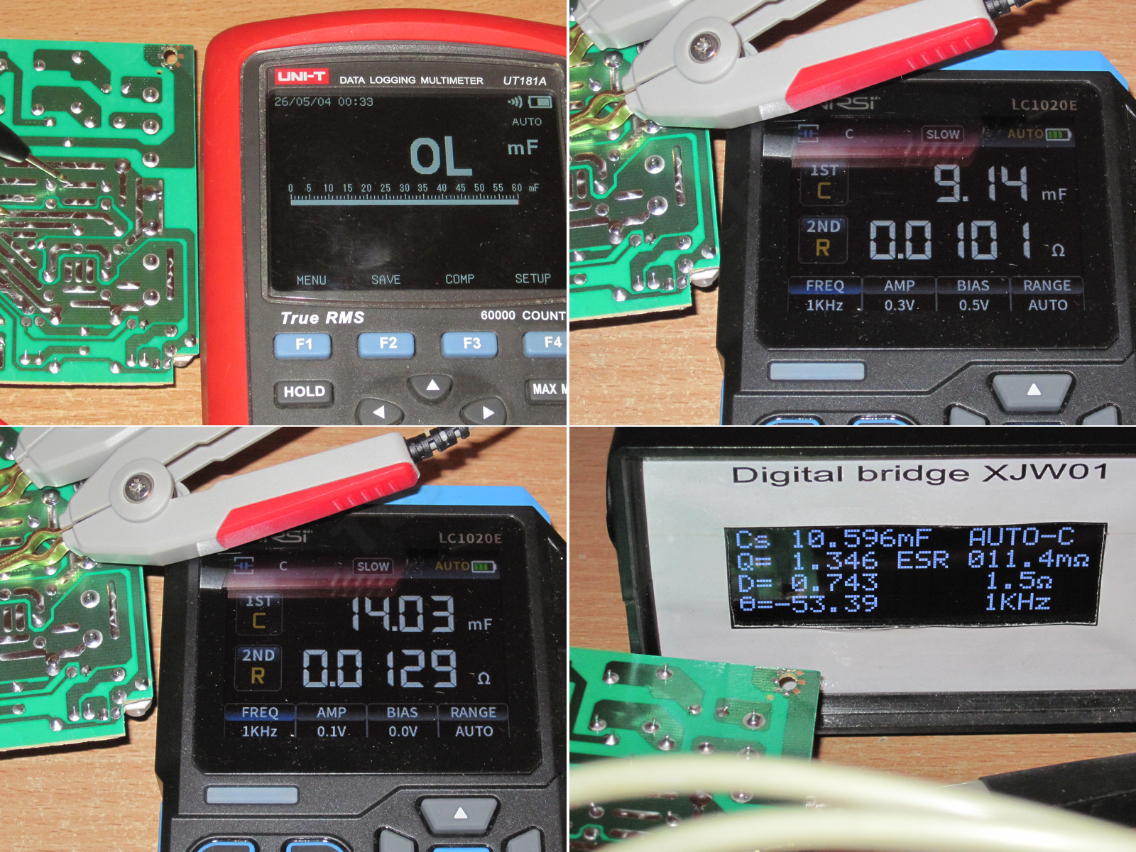
And here I could have said everything was great, if not for yet another “but.”
I was recently putting together another review of some more power supplies, this time 5 V models. The plan was to measure the capacitors’ capacitance without desoldering them from the board. But then came an unexpected snag.
First, the multimeter refused to measure them. Second, I tried the Fnirsi, but no matter what I tried, I couldn’t get stable, sensible readings. With the offset enabled, the results were at least somewhat close, though they still jumped around. With the offset disabled, the readings varied from about 8000 to 14000 µF.
And third, I looked at all this, got out the meter I’m used to, connected it, and took a measurement. Its readings barely drifted at all—just a tiny bit.
Of course, you’ll ask what the output capacitance was. There were five 2200 µF capacitors in parallel, so... about 11,000 µF, since the old little meter happened to give the closest reading.
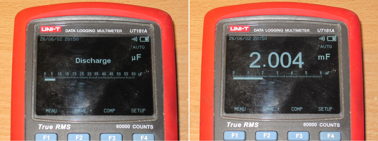
And since the multimeter made it into the shot, let me remind you—and strongly recommend—always discharge capacitors before measuring them!!!!
Why did I bring this up? Well, I once tried measuring the capacitance of an input capacitor charged to about 250 V with a multimeter. Think something bad happened? Nope, it simply displayed “Discharge,” then measured the capacitance. It turns out that if this multimeter detects a charged capacitor, it discharges it first and only then takes the measurement. But LCR meters usually don't have this kind of protection, so if you try this, you may end up having to buy a new meter.
And of course, inductance. I don't have anything precision-grade here, and in general the variation is usually greater with these, since most of mine are power inductors. Still, let's see if we can get some kind of estimate.
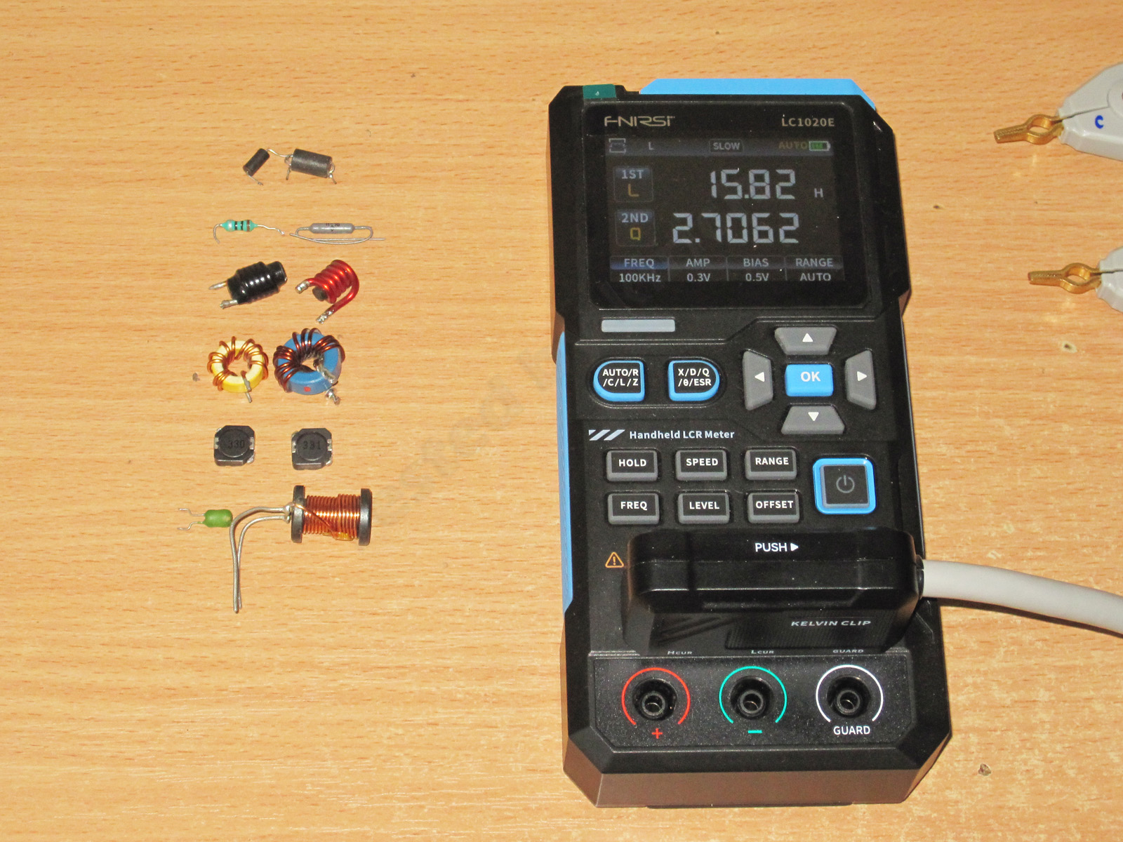
For the test, I picked six types of inductors, two of each type, which seems like plenty to me.
1. A ferrite bead on a wire, both a single bead and one with several turns.
2. Axial inductors: an imported 10 µH one and a Soviet 100 µH one.
3. Rod-core inductors, probably from power supplies or motherboards, two types.
4. Toroidal inductors with a core made of distributed-gap material, clearly from motherboards.
5. Pot-core inductors, 33 and 330 µH.
6. Drum-core inductors, 22 and 220 µH.
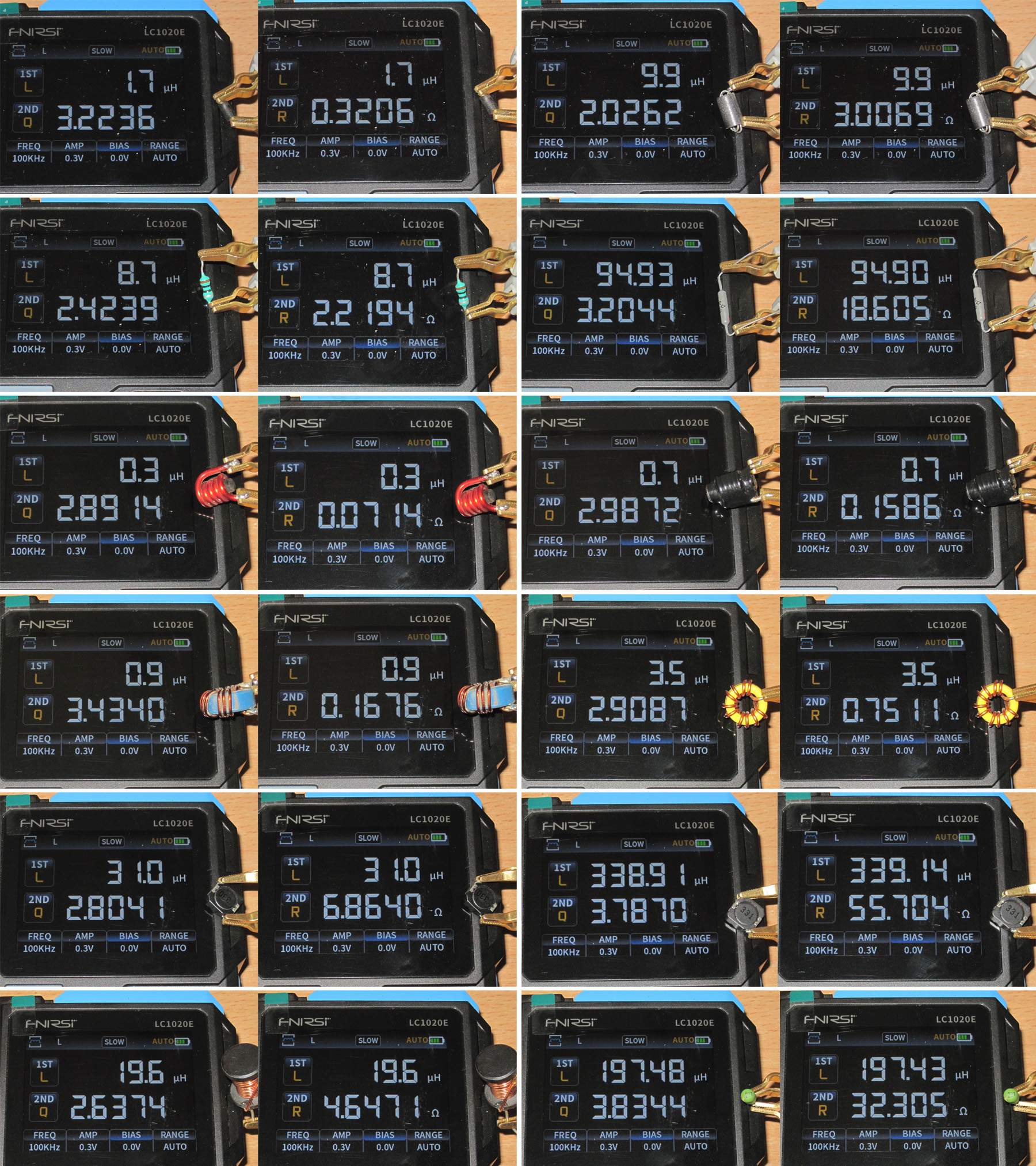
First, I measured the Q factor and ESR of each one at 100 kHz, which is a perfectly normal operating frequency for components like these.
I don't really have anything to cross-check the results against, since my old meter doesn't work at these frequencies. And in this case, I don't think a comparison would be valid anyway.
Subjectively, the results look quite reasonable.
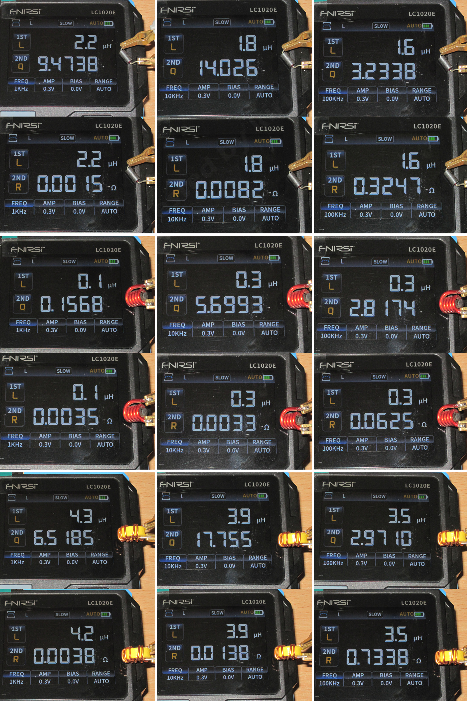
Here I used a different set of measurements, taking some of the inductors tested above and running six tests:
1. Three Q factor measurements at 1, 10, and 100 kHz.
2. Three ESR measurements at 1, 10, and 100 kHz.
3. And three inductance measurements at 1, 10, and 100 kHz, though these are overall measurements.
First, a single bead on a wire, a fancy rod-core inductor, and a toroidal one.
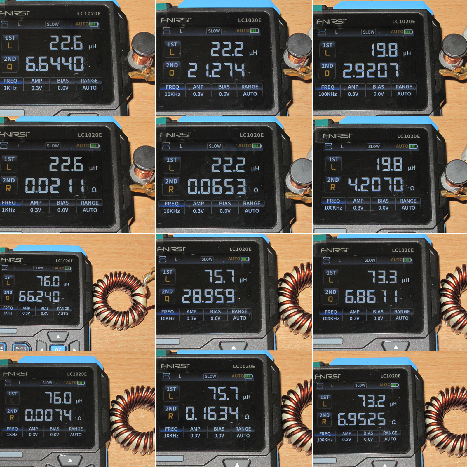
Also, a 22 µH drum-core inductor. I decided to add one more inductor here, wound on an Alsifer core. It's some kind of Soviet part, probably from military equipment, and quite old.
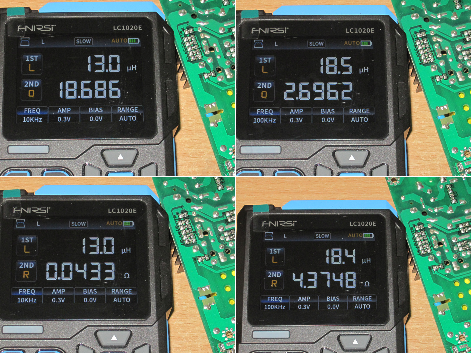
More as an extra, I tried measuring the primary and secondary windings of a switching transformer. I didn't desolder it, so the measurement isn't entirely valid in this case. I can measure a similar one off the board if needed.
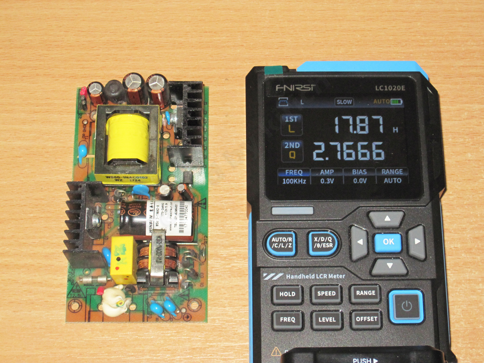
Inductance, Q factor, and ESR of the primary winding at 10 and 100 kHz.
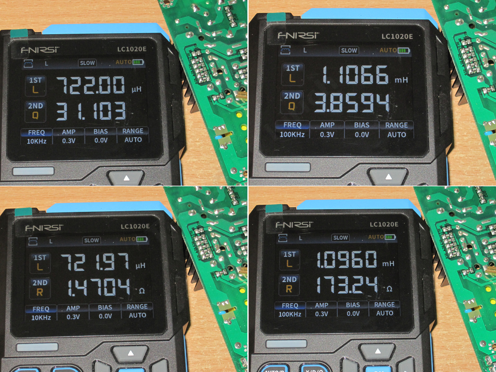
And the secondary winding.
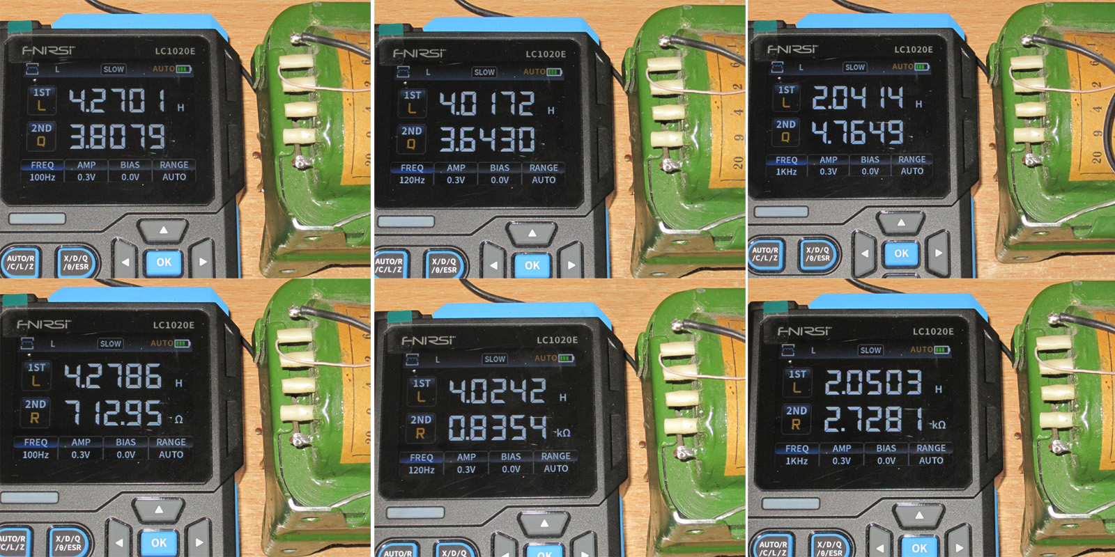
And finally, a regular 50 Hz TPP270 transformer, primary winding.
Out of curiosity, I measured its inductance, Q factor, and ESR at 100 Hz, 120 Hz, and 1 kHz.
Everywhere you look, including the description for this device, it says to discharge the capacitor before measuring it. And I keep wondering: is it really so hard to add protection? If I try to measure the capacitance of a charged capacitor with my multimeter, it first displays “Discharge” and only starts measuring once the capacitor has been discharged. In fact, I once measured the input filter capacitor in a power supply, charged to at least 200–250 V, and guess what? It discharged and measured that one too.
Conclusions.
In my opinion, this device is a mixed bag, and I have several reasons for saying so.
But first, here's what I liked about it in its own right and compared with my old meter. Mostly, it's the ease of use and the case form factor, as well as the built-in battery (though my old one has one too). I would say I liked the informative display, but it's a bit of a mixed blessing. My old meter basically shows everything on the screen at once, while this one displays only two parameters: a primary and a secondary one.
Measurement modes, 10 and 100 kHz frequencies, the option to enable bias and select the test voltage, a sorting function—in short, there's a lot here.
Of course, I'll also mention what I didn't like. At the very least, some of the stated specifications don't match reality. For example, it says you can measure capacitors up to 1,000 µF at 10 and 100 kHz. In practice, that's not the case: for some reason, I had trouble measuring even a 47 µF capacitor at 100 kHz, and I couldn't measure a 680 µF capacitor even at 10 kHz.
Measuring low resistances raises just as many questions. For values below about 10–20 mΩ, forget about accuracy. I also noticed that when it can't measure something properly, the readings start jumping all over the place. So it's not just a matter of measurement error; sometimes it simply can't do the job.
The ergonomics could be better. For example, the button label doesn't match its function, and it doesn't fully remember the last operating mode. And the cherry on top: auto power-off doesn't work. That's a deal-breaker. Actually, there's one more little thing: the manual was written by someone who had clearly never even seen the device, otherwise they'd know what the main screen looks like.
Yes, somehow I found more drawbacks than advantages. Still, I've been using it for a while now, and I can say that its strengths are ease of use and a good-quality display—in short, it's just convenient. Once you get used to it and know where you can trust it and where you can't, it's perfectly fine.
Even so, something else really surprised me: my old XJW01, which is basically a DIY device, outperformed it in some tests. For example, it can measure low resistances, which the Fnirsi can't. The same goes for capacitance measurements: I showed that the XJW01 does a better job in-circuit. No, that's not quite right—the XJW01 can measure things the Fnirsi can't. I haven't looked into why. But the XJW01 is somewhat outdated; it's been around for many years, though in my opinion it still rules.
I didn't take it apart because I simply don't see the point, and other reviews have shown the internals plenty of times.
The store provided the promo code FNSCD325, which, as I understand it, gives a $3 discount. Valid from: 01.06.2026 – 10.06.2026
That's probably all for now. I hope this was useful.
$52.54
This page was found when searching for:
фнирси 1020, lc1020e инструкция на русском, фнирси lc1020 обзор, инструкция на русском ic1020e, для фнирси 1020 инструкция на русском в pdf, fnirsi lc1020e скачать инструкцию на русском языке бесплатно, fnirsi lc1020e инструкция на русском, lcr фнирси 1020 фото
фнирси 1020, lc1020e инструкция на русском, фнирси lc1020 обзор, инструкция на русском ic1020e, для фнирси 1020 инструкция на русском в pdf, fnirsi lc1020e скачать инструкцию на русском языке бесплатно, fnirsi lc1020e инструкция на русском, lcr фнирси 1020 фото
This model is included in the summary table: Comparison of measuring instruments reviewed on the blog
The figures from this review are in the measurement database: Measuring instruments
Calculate manuallyAll calculators
Discounted products
You may be interested in



Discounted products
Support the project
All the content on the site and the advice are free, but we’d be grateful for your support of the project and the channel!
Discuss on the forumHave a question or some experience to share? Discuss the article with the author and readers: the forum is a convenient place to share schematics and photos.
Go to the forumOnly registered readers can comment. It takes a minute to sign up, and you can log in with the same account you use on the forum.
Log inRegister