
A pair of 36 W and 60 W power supplies in an unusual form factor
I received another batch of various power supplies for testing, and among them were some unusual ones in round cases, so I decided to start with those :)
To keep up with new posts on the blog, I recommend following me on Instagram, where I'll post notifications about new articles and maybe write about something interesting too - link to my account
You can also subscribe to updates and new articles on the Telegram channel - https://t.me/KirichBlog
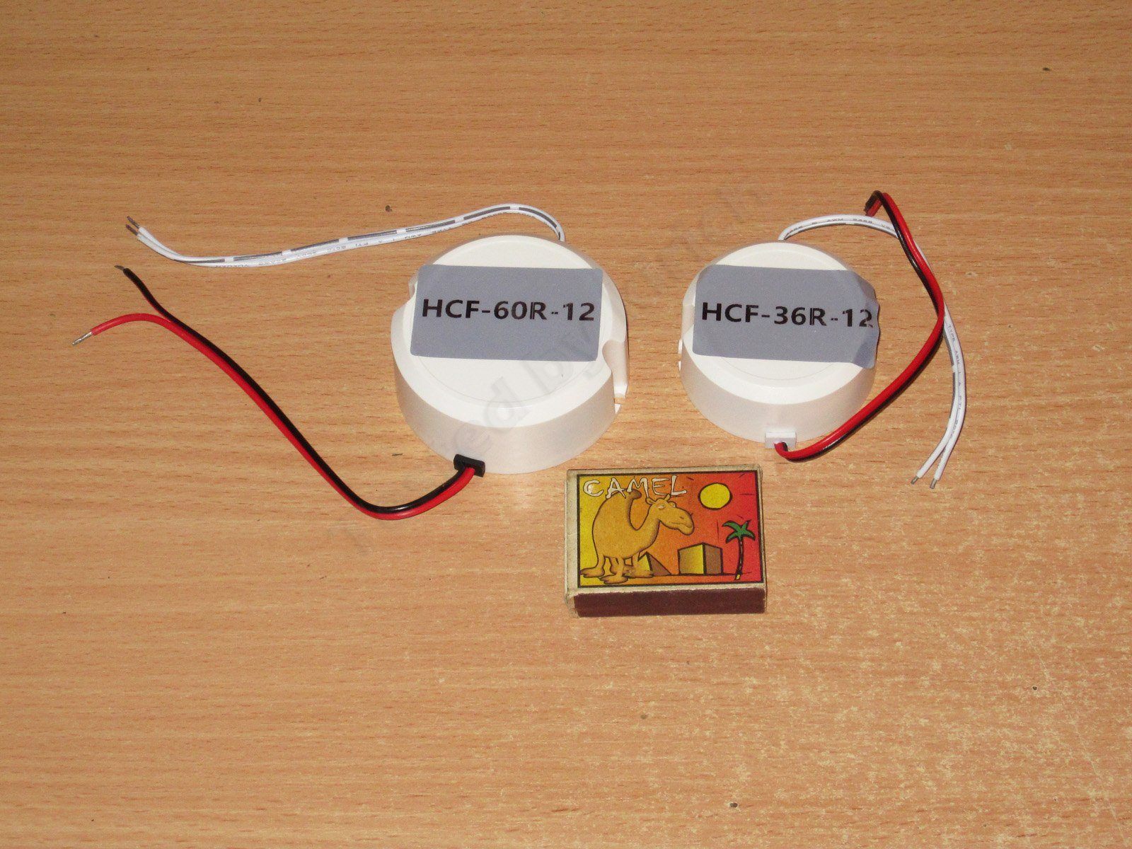
The 12 V power supplies differ in appearance only by size: the 36 W model is 55 mm in diameter and 22 mm high, while the 60 W model is 65 mm in diameter and 26 mm high.
But it turned out that the power supplies differ much more significantly than I first thought.
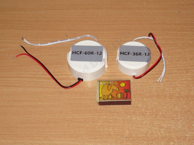
I'll start with the 36 W version, model HCF-36R.
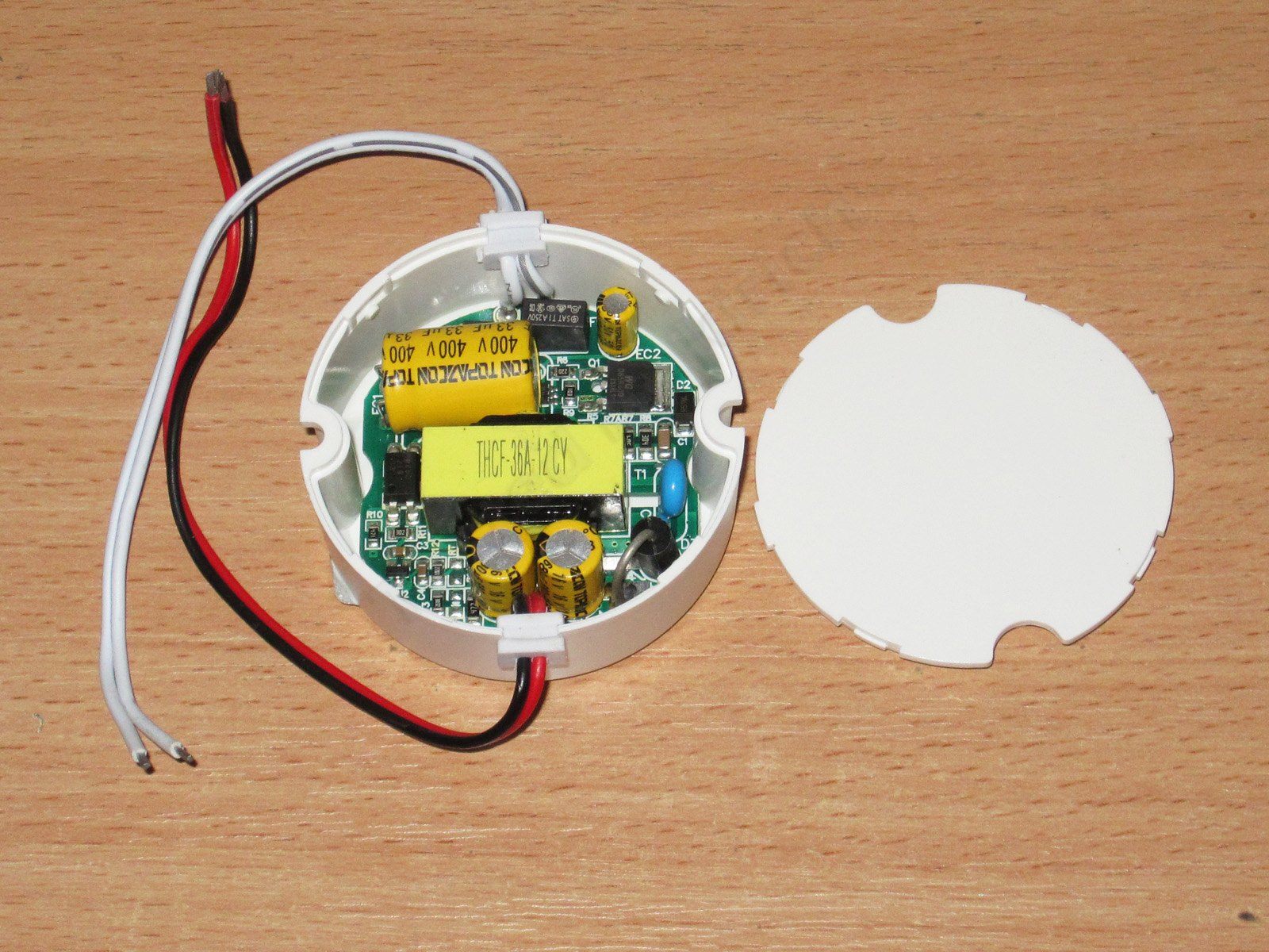
The case is extremely easy to open. Inside is a round circuit board, and overall I have no complaints about the workmanship.

The board layout is fairly compact, but not excessively so. At this point, judging by the type of output diode, I started having doubts about the claimed 3 A output current.
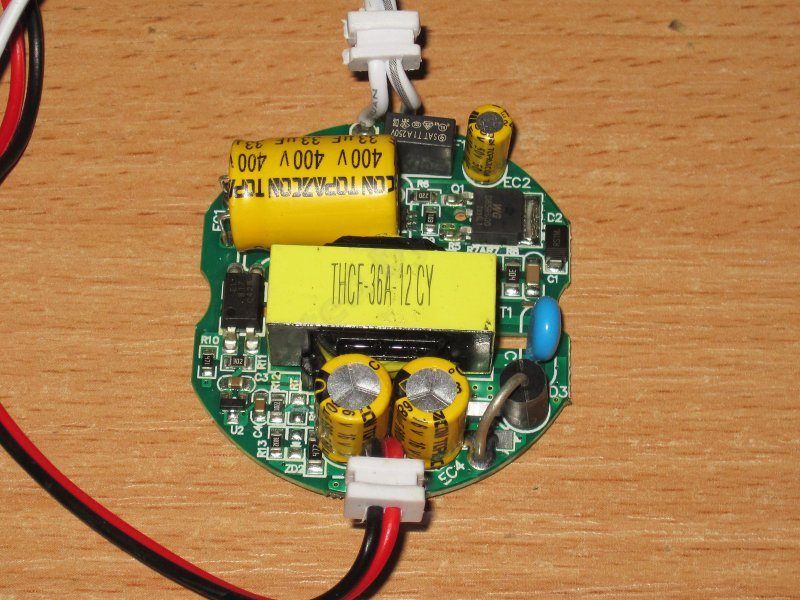
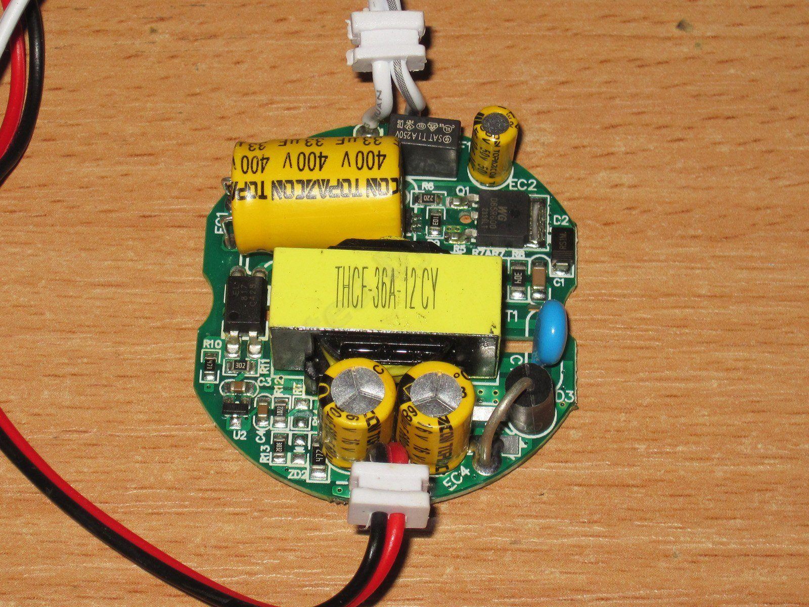
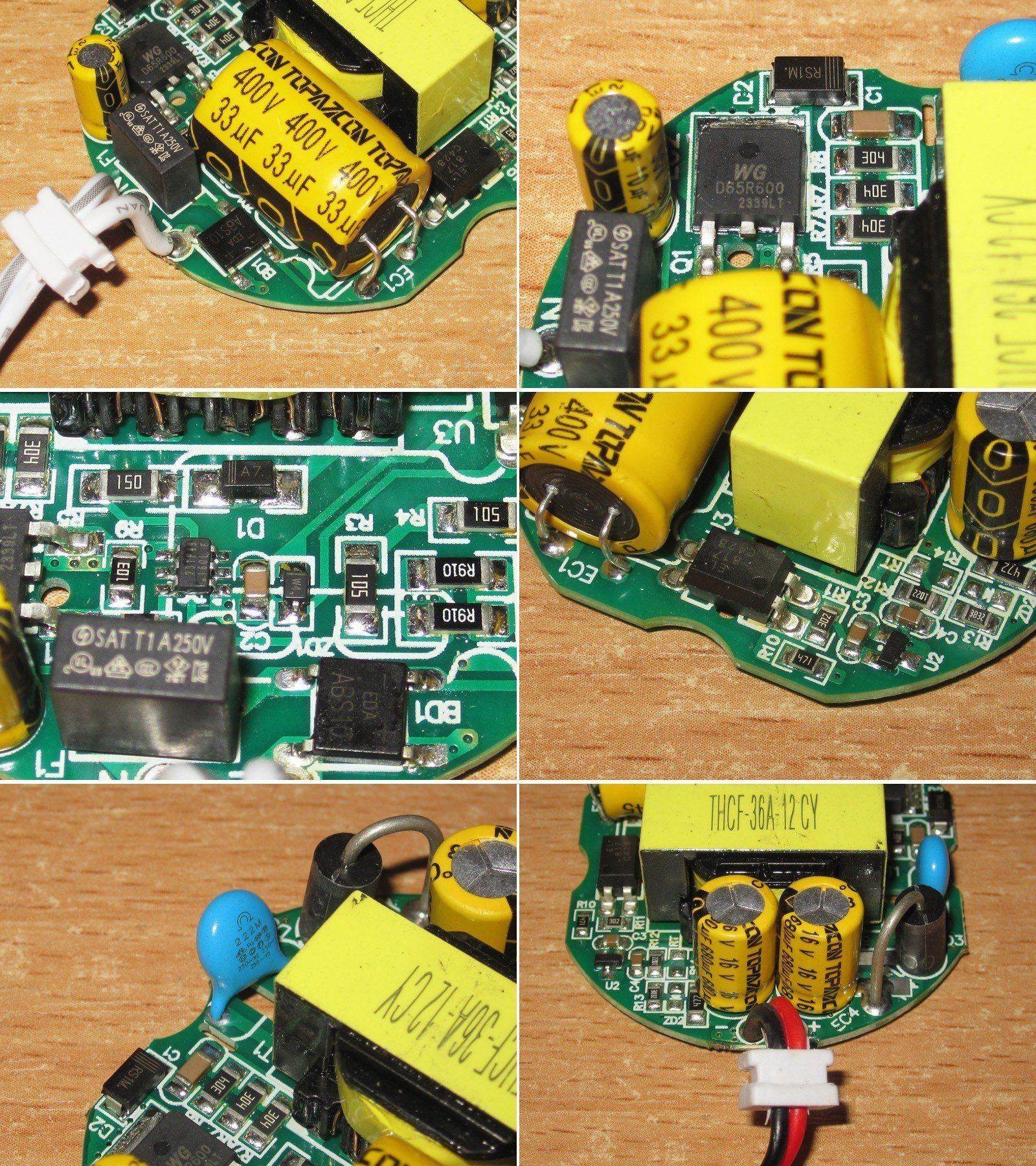
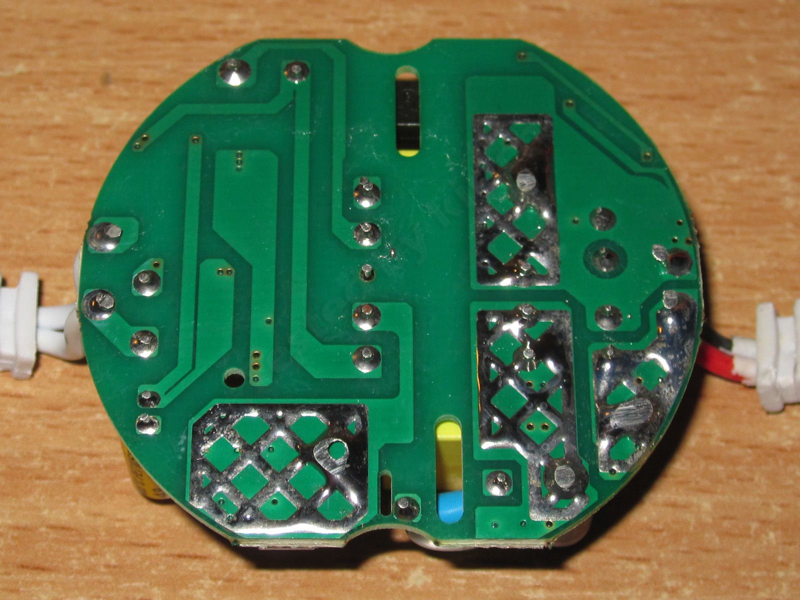
1. At the input, there's a 33 µF capacitor, a bridge rectifier, and a fuse. There's no thermistor, filter, or varistor; everything is heavily simplified.
2. The transistor is marked 65R600, presumably rated for 650 V and 0.6 Ω.
3. The controller and its surrounding components are all pretty standard.
4. The feedback optocoupler and its monitoring circuitry. There's a protective slot, which is good to see.
5. The Y capacitor. They've added a slot here too, which is good.
6. On the output side, there are two 680 µF, 16 V capacitors, as well as the output diode. Diodes like this are usually rated for a maximum current of 3 A. And it's not enough just to install one: to dissipate that much heat, you also need good copper planes underneath it. So 3 A is the absolute maximum for this diode, and the actual limit is much lower, since you need some headroom too.
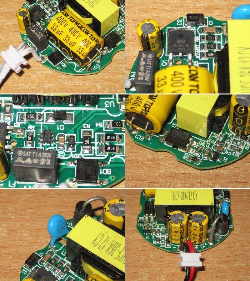
No complaints about the board layout; all the required clearances are there.
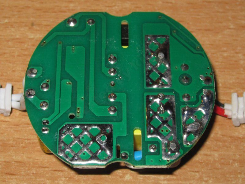
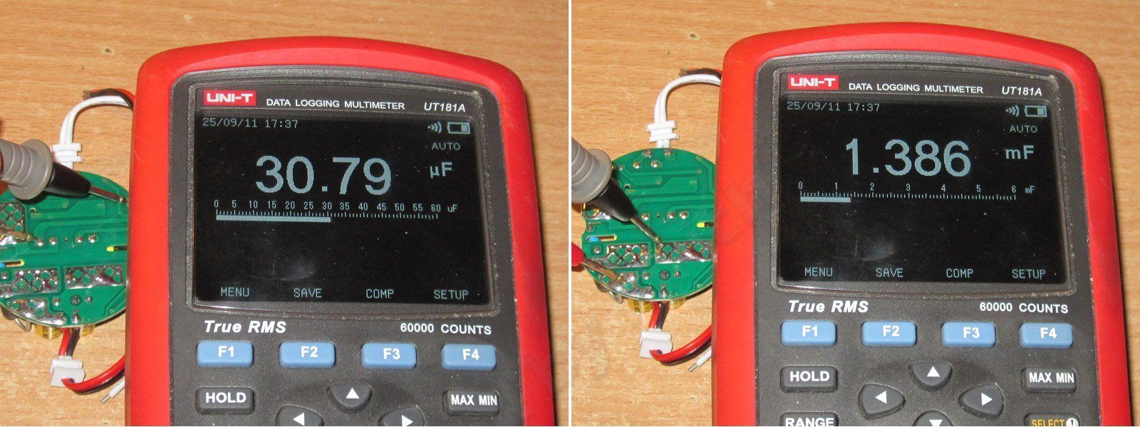
The input and output capacitor values match the specifications and are perfectly adequate for this power/current level.
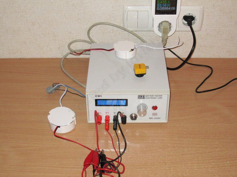
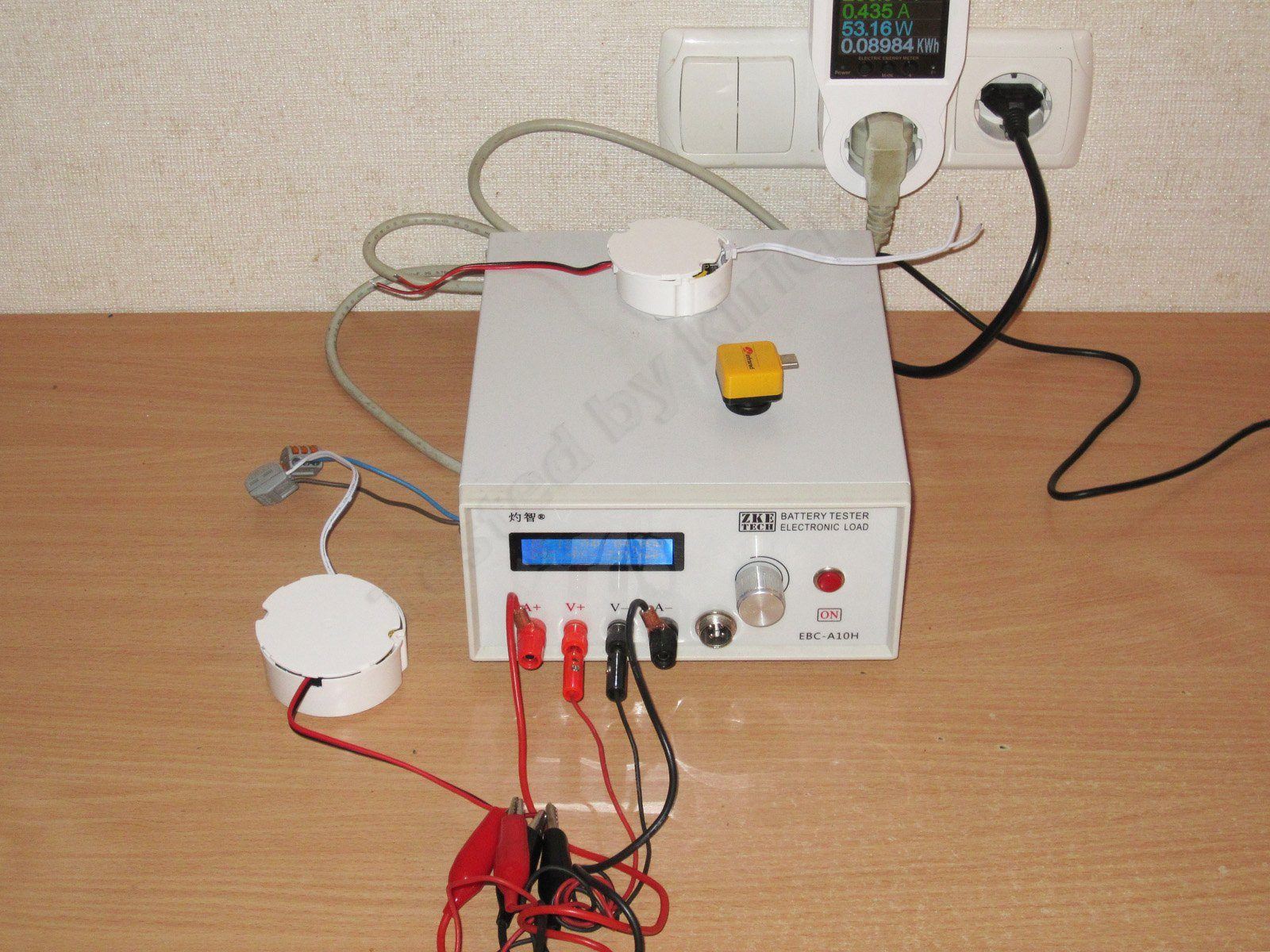
For testing these power supplies, as well as all the later models in this series, I used an EBC-A10H electronic load, mainly because it makes plotting graphs convenient. For efficiency measurements, though, I used a load based on the CL24, since unfortunately the EBC-A10H can't be controlled on the fly while it's running.
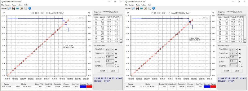
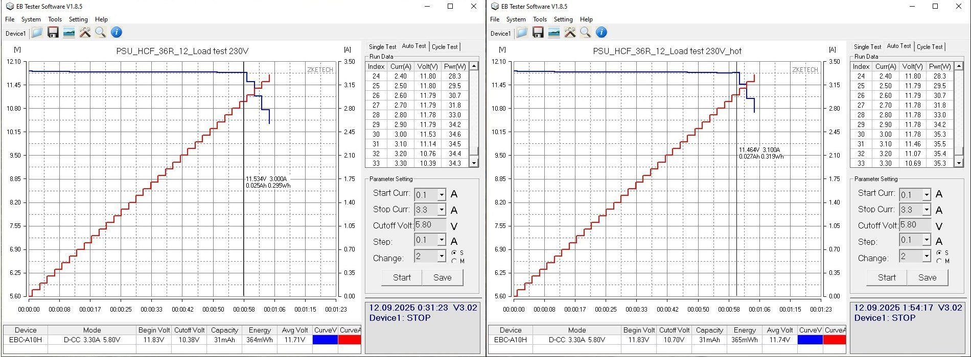
The protection trips at around 3–3.1 A when cold. When hot, it's about the same, perhaps a little higher.
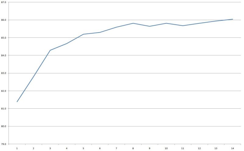
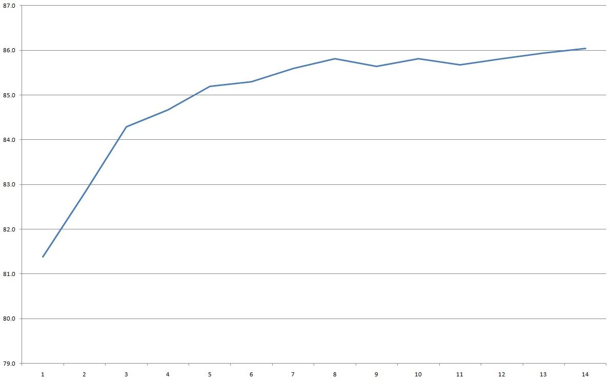
Efficiency is around 85–86%. I wouldn't call that high, but I expected even less. The horizontal scale is 0.2 A per division.
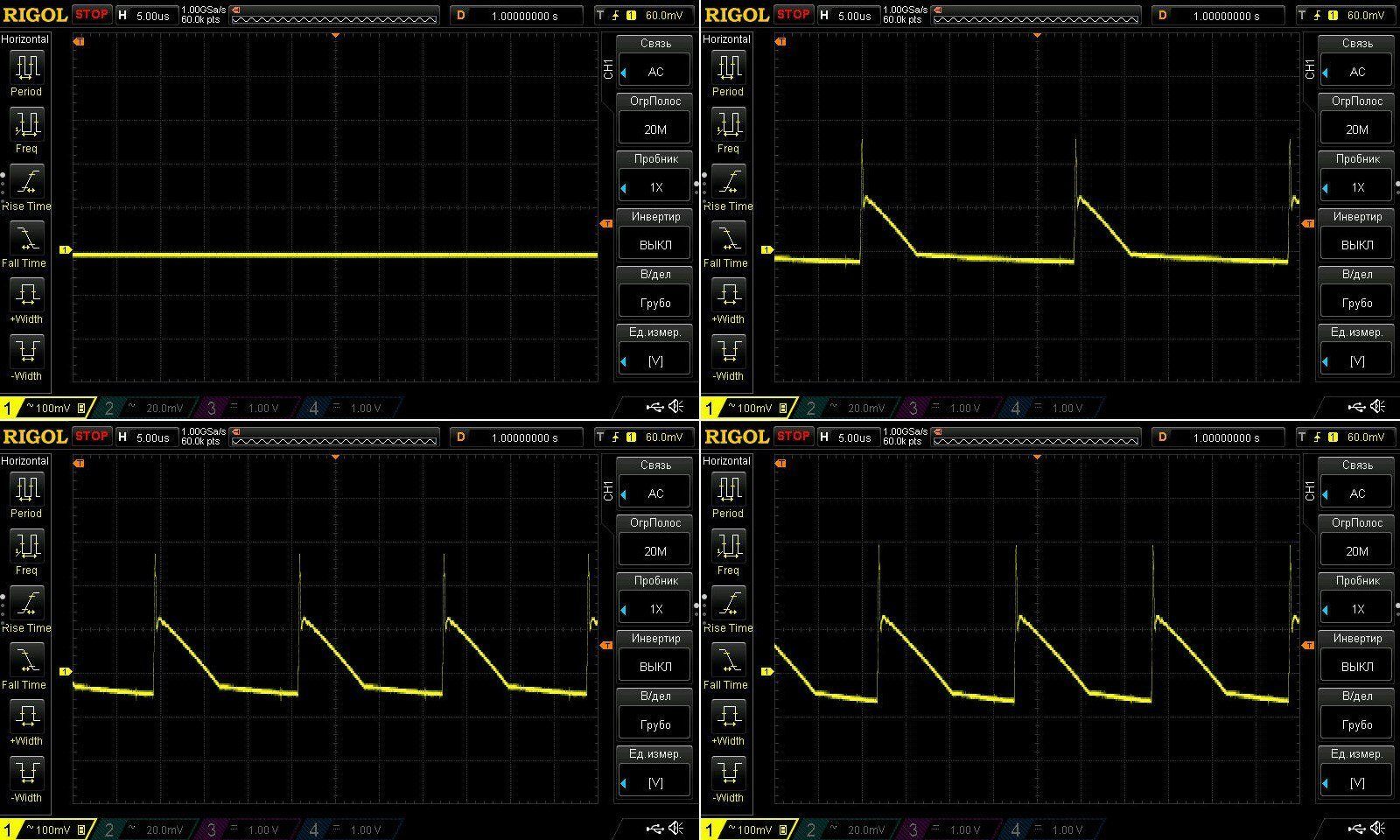
Ripple is more acceptable than bad, but it could be better. These are the results with no load and at currents of 1, 2, and 2.7 A.
At 2.7 A, total ripple is about 370 mV, with the main component around 200 mV.
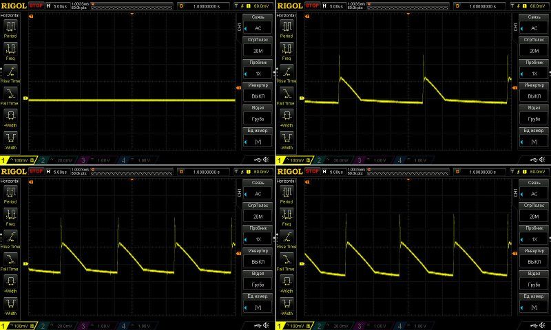
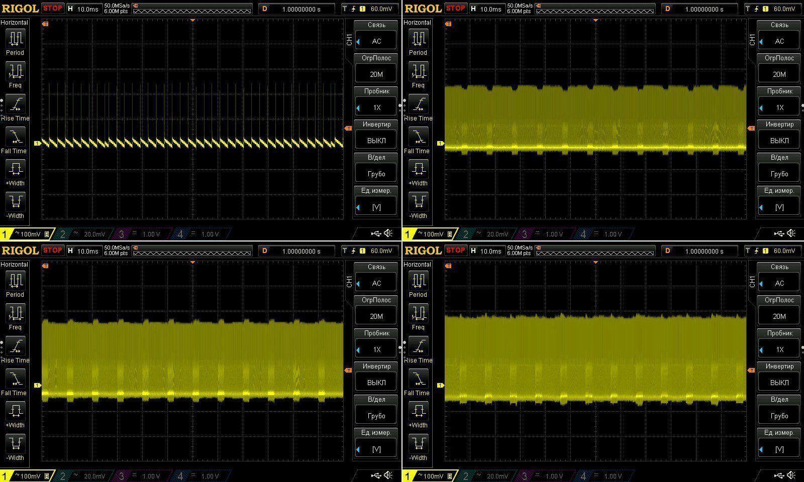
At 100 kHz, things are generally pretty good. With no load, the PWM controller lowers the frequency—or, more precisely, switches to “green” mode. Power supplies often “whine” in this mode, but there are no issues with that here.
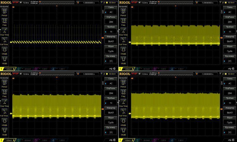
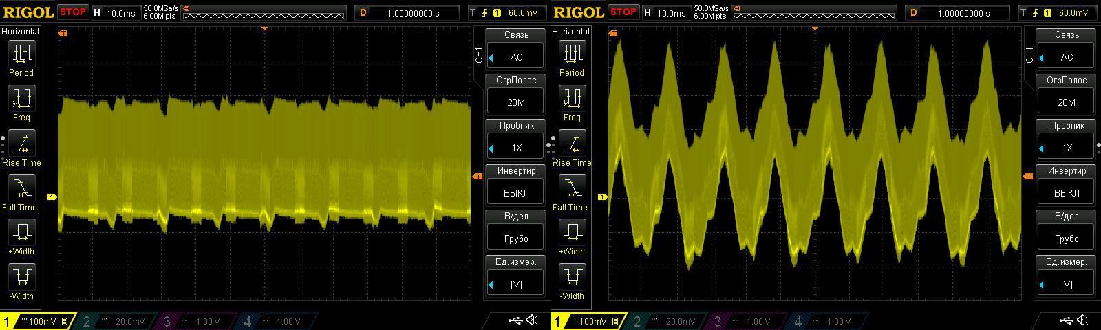
At 2.9 A, ripple starts to increase, and at 3 A the PWM controller tries to limit the current, making the waveform look really unpleasant.
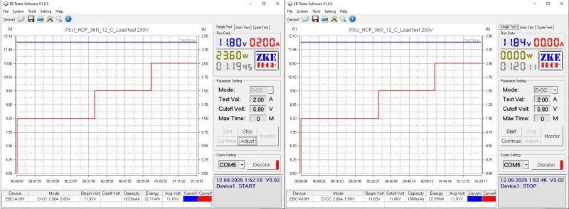
The long-duration test was run at 1, 1.5, and 2 A, and was stopped because the temperature got quite high. I usually monitor the temperature of the main components during testing: the transistor, transformer, output diode, and so on. Each component has its own temperature limit, and when it approaches that limit, the test is stopped. In practice, that gives us the maximum continuous power. The short-term power, on the other hand, is determined by the protection trip point. Sometimes the long-term and short-term ratings are the same, but more often they aren't.
I should point out the very good voltage regulation and almost no temperature dependence.
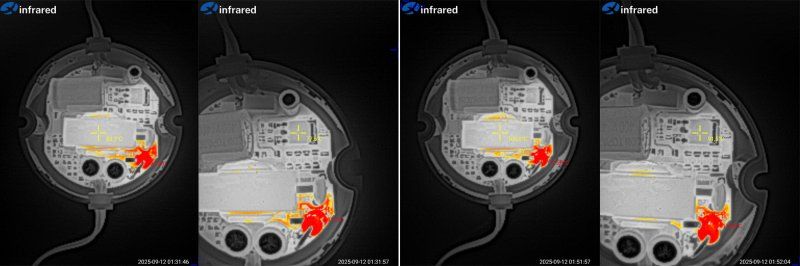
The temperatures are quite predictable. Here are the results at 1.5 and 2 A.
There isn't much to see at 1.5 A, but at 2 A you can see that the transformer is already at 100 degrees, while the output diode is almost at 120, which was entirely predictable.
In practice, this gives us a power supply rated for around 18–20 W continuous output, or 1.5 A.
And now for the big brother—and it looks like a half-brother—the HCF-60R.
The layout is basically the same, but the case and circuit board are a little larger.
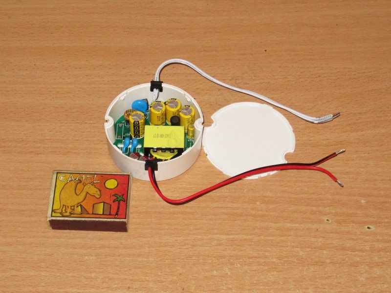
It's clear right from the start that this unit is considerably more complex: more capacitors, a larger transformer, and so on.
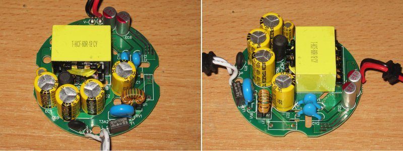
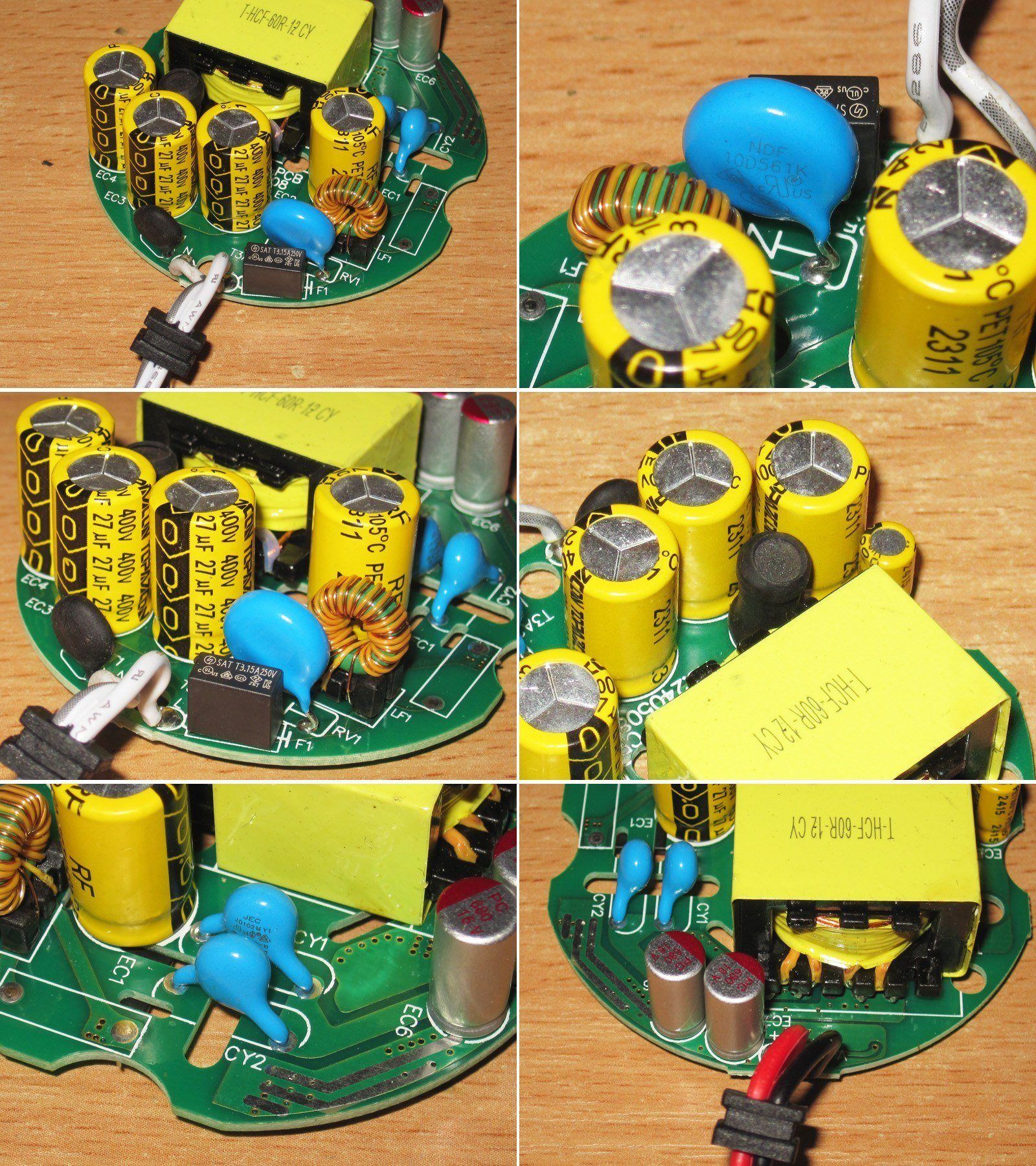
1. The input has a fuse, bridge rectifier, inductor, and varistor. There are no EMI suppression capacitors or thermistor.
2. The varistor is rated for a 560 V peak voltage, so it's essentially only there to protect against mains surges.
3. There are four 27 µF capacitors, which is more than enough for a 60 W power supply on our mains voltage, and also quite sufficient for 115–120 V.
4. There's an additional inductor in the input capacitor circuit to reduce ripple in that circuit.
5. There are two Y capacitors, which is quite rare. I've seen Mean Well units with two in series, but here they're connected differently: on the hot side, one goes to the positive rail of the high-voltage circuit and the other to the negative rail; on the cold side, both go to the output negative.
6. The output has a pair of 680 µF, 16 V polymer capacitors, which looks good to me.
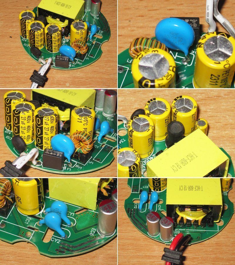
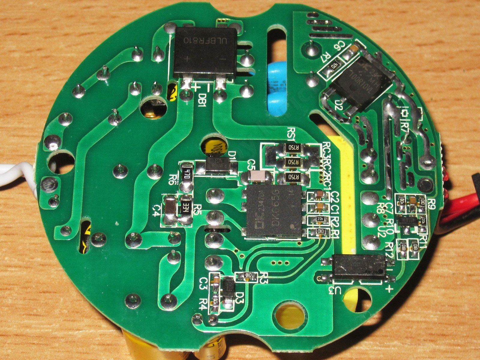
The previous power supply had a completely bare underside of the circuit board; here it's the opposite, with most of the components mounted there.
I should point out the safety slots, as well as the relatively modern optocoupler in a long package.
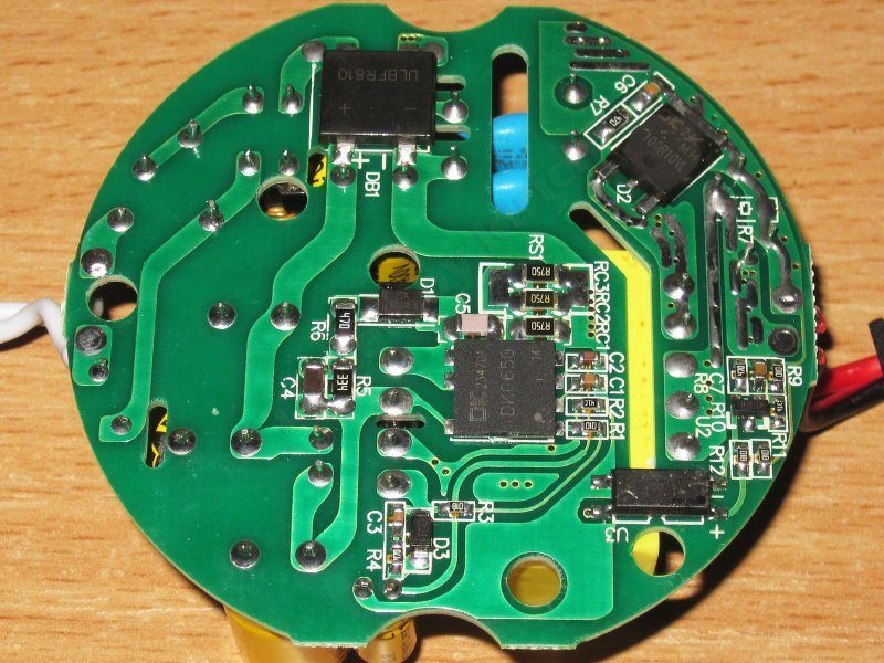
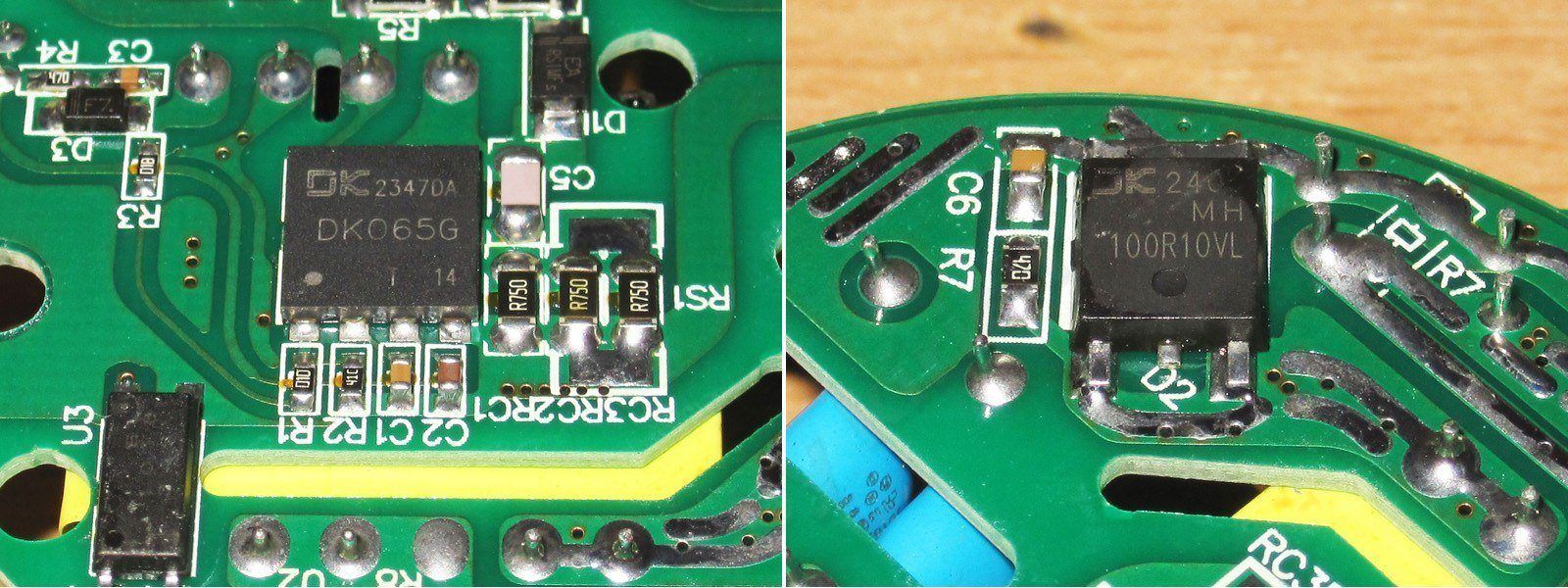
And here's the main difference: this power supply is built around GaN-based chips, which came as a complete surprise to me. This controller is designed for power supplies rated at around 65 W.
The output has a component that looks like a typical diode array, but judging by the specs and my test results, I suspect it's a synchronous rectifier. Unfortunately, searching turned up no information about this component.
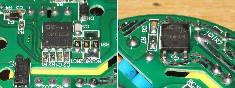
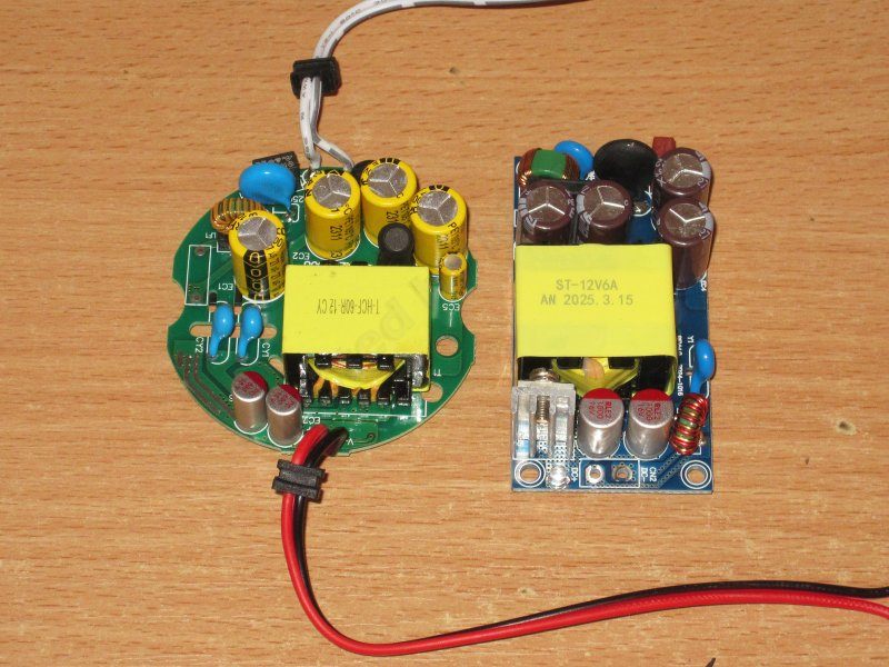
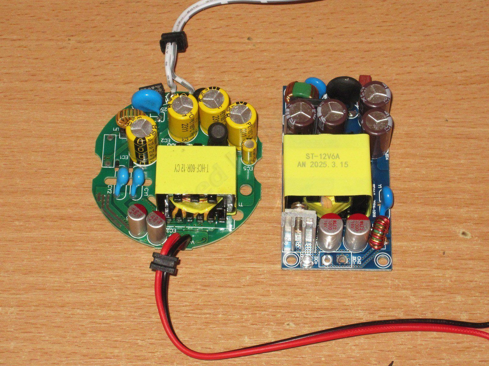
By the way, speaking of GaN and all that. I've got a few small power supplies from AliExpress at home, rated at 72 W: 12 V, 6 A and 24 V, 3 A. It turns out they have a lot in common with the one I'm reviewing: exactly four input capacitors, polymer capacitors on the output, and the same PWM controller. It'll be interesting to test these little guys :)
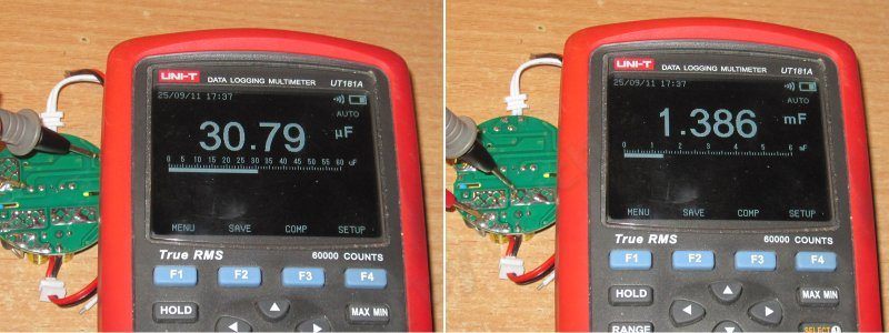
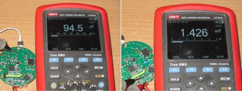
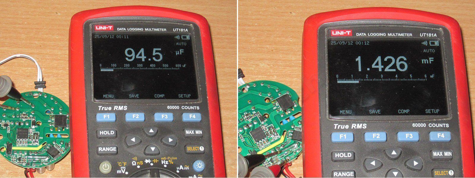
The total measured capacitance is 95 µF for the input capacitors and 1430 µF for the output capacitors, more than enough for 230 V mains and quite acceptable for 115–120 V.
The protection is correctly set for the rated current of 5 A: 5.5–5.6 A when cold and 5.4–5.5 A when hot. As you can see, it's threshold-based: it shuts off the output under overload rather than reducing the voltage. Sometimes that matters.

Efficiency from 0.5 to 5 A, in 0.5 A increments. Yes, the results are better here: 90–91% versus 85–86% for the previous unit. But if the output really does use a synchronous rectifier, efficiency could be even better.

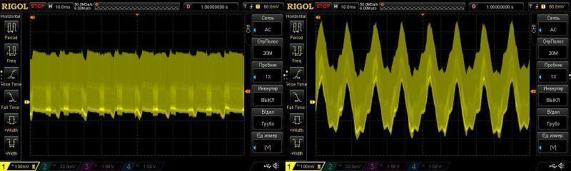
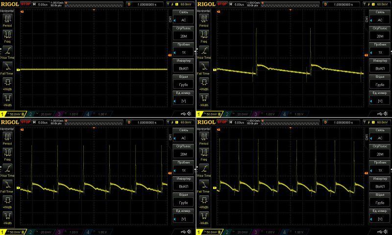
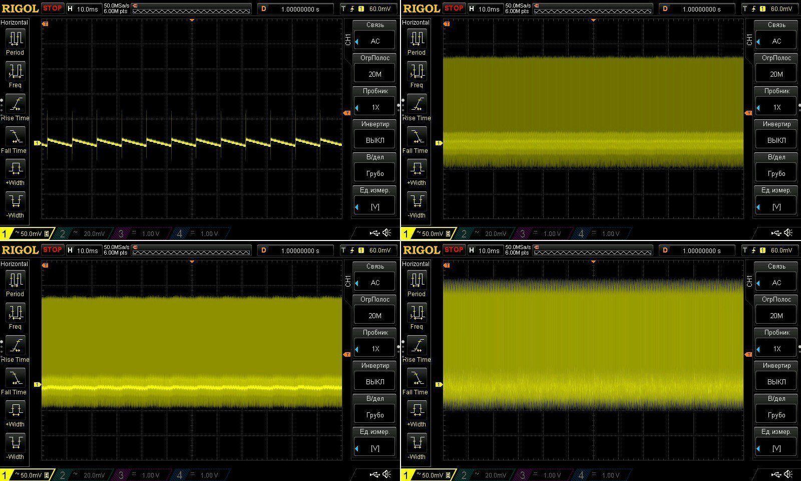
Ripple is lower here, thanks to the polymer capacitors. Results with no load and at currents of 1.5, 3, and 5 A.
I'd say it's all very good: the main ripple component is just 50 mV, but the spikes, with an amplitude of around 220 mV, gave me some pause. The value itself isn't particularly high, but the large difference from the main section is concerning.
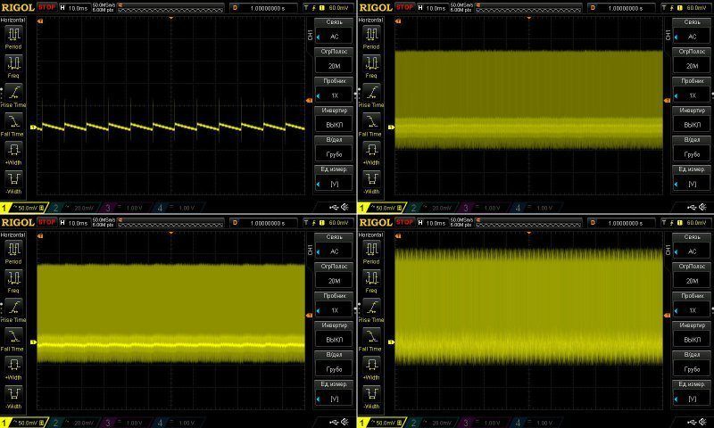
It's also noticeable that the PWM controller adjusts the frequency over a fairly wide range.
At low frequency, everything is fine, both in terms of the full swing and the absence of 100 Hz ripple.
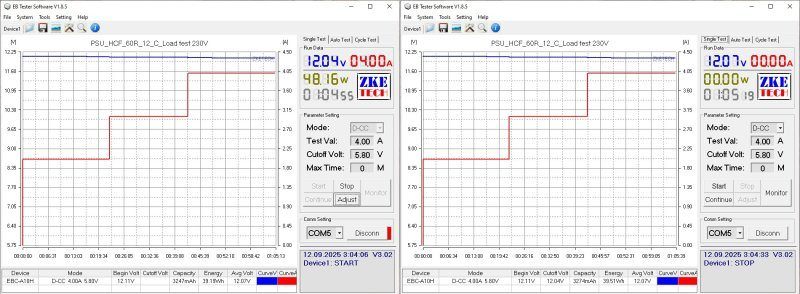
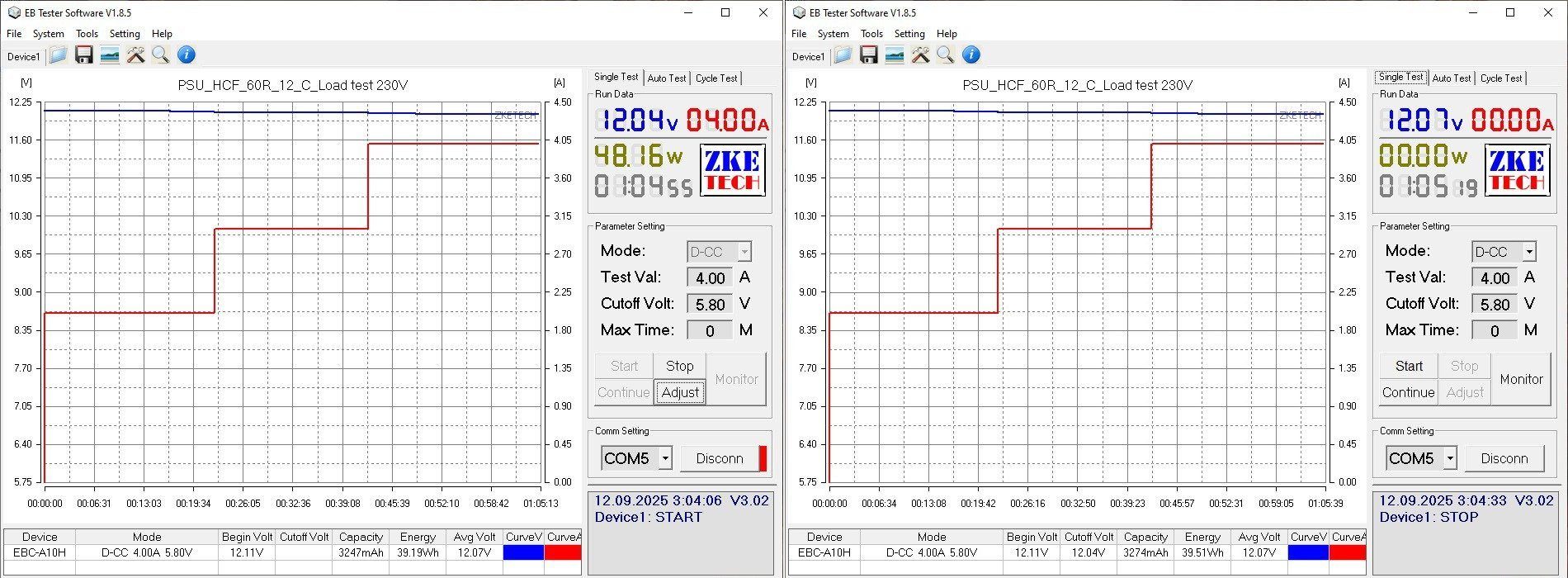
I ran the thermal test at currents of 2, 3, and 4 A. The power supply holds its voltage very well under load; the difference here is due only to the output wires. There's a slight negative effect from heating, but it's just 40 mV.
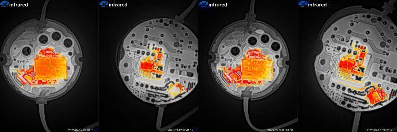
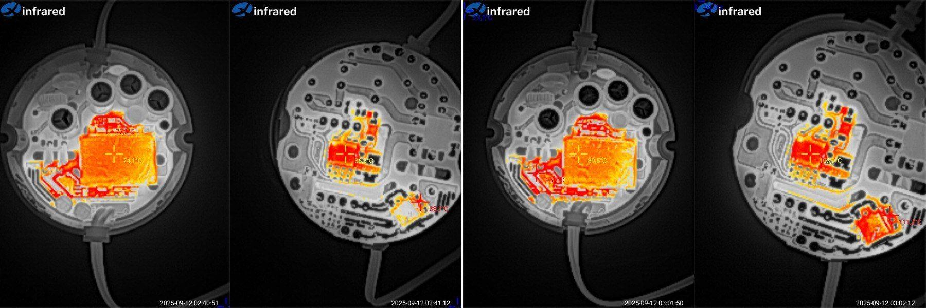
And here are the temperatures. Below are photos taken after the 3 A and 4 A tests.
At 3 A, everything is excellent. At 4 A, temperatures are still acceptable overall: 90 degrees on the transformer and 103 on the PWM controller. But the output diode temperature concerned me: 111 degrees.
In my opinion, this power supply's continuous current rating is around 3.5–4 A; I wouldn't run it at a higher load for extended periods.
Conclusions.
I wrote above that these power supplies are like brothers, but only half-brothers. The point is that the two units are actually quite different in terms of circuit design, components, and specifications. The main things they have in common are the same form factor and the fact that neither can deliver its rated power continuously. Actually, that's not quite true: neither model raises any concerns in terms of electrical safety, which, incidentally, is far from always the case with Chinese power supplies.
Still, if we look at the shortfall as a percentage, the 60 W model comes noticeably closer to its rated 60 W and can actually deliver around 45 W continuously.
Overall, the first one is suitable for powering low-power loads. In theory, you could install it in a wall box, but only if you reduce the load. I liked the second one much more: it has modern components and delivers quite good results in terms of ripple and heat.
That's all for now. I hope you found this information useful, and thanks again to Vitaly for providing these samples of Chinese industry for testing :)
To keep up with new posts on the blog, I recommend following me on Instagram, where I'll post notifications about new articles and maybe write about something interesting too - link to my account
You can also subscribe to updates and new articles on the Telegram channel - https://t.me/KirichBlog
The 12 V power supplies differ in appearance only by size: the 36 W model is 55 mm in diameter and 22 mm high, while the 60 W model is 65 mm in diameter and 26 mm high.
But it turned out that the power supplies differ much more significantly than I first thought.
I'll start with the 36 W version, model HCF-36R.
The case is extremely easy to open. Inside is a round circuit board, and overall I have no complaints about the workmanship.
The board layout is fairly compact, but not excessively so. At this point, judging by the type of output diode, I started having doubts about the claimed 3 A output current.
1. At the input, there's a 33 µF capacitor, a bridge rectifier, and a fuse. There's no thermistor, filter, or varistor; everything is heavily simplified.
2. The transistor is marked 65R600, presumably rated for 650 V and 0.6 Ω.
3. The controller and its surrounding components are all pretty standard.
4. The feedback optocoupler and its monitoring circuitry. There's a protective slot, which is good to see.
5. The Y capacitor. They've added a slot here too, which is good.
6. On the output side, there are two 680 µF, 16 V capacitors, as well as the output diode. Diodes like this are usually rated for a maximum current of 3 A. And it's not enough just to install one: to dissipate that much heat, you also need good copper planes underneath it. So 3 A is the absolute maximum for this diode, and the actual limit is much lower, since you need some headroom too.
No complaints about the board layout; all the required clearances are there.
The input and output capacitor values match the specifications and are perfectly adequate for this power/current level.
For testing these power supplies, as well as all the later models in this series, I used an EBC-A10H electronic load, mainly because it makes plotting graphs convenient. For efficiency measurements, though, I used a load based on the CL24, since unfortunately the EBC-A10H can't be controlled on the fly while it's running.
The protection trips at around 3–3.1 A when cold. When hot, it's about the same, perhaps a little higher.
Efficiency is around 85–86%. I wouldn't call that high, but I expected even less. The horizontal scale is 0.2 A per division.
Ripple is more acceptable than bad, but it could be better. These are the results with no load and at currents of 1, 2, and 2.7 A.
At 2.7 A, total ripple is about 370 mV, with the main component around 200 mV.
At 100 kHz, things are generally pretty good. With no load, the PWM controller lowers the frequency—or, more precisely, switches to “green” mode. Power supplies often “whine” in this mode, but there are no issues with that here.
At 2.9 A, ripple starts to increase, and at 3 A the PWM controller tries to limit the current, making the waveform look really unpleasant.
The long-duration test was run at 1, 1.5, and 2 A, and was stopped because the temperature got quite high. I usually monitor the temperature of the main components during testing: the transistor, transformer, output diode, and so on. Each component has its own temperature limit, and when it approaches that limit, the test is stopped. In practice, that gives us the maximum continuous power. The short-term power, on the other hand, is determined by the protection trip point. Sometimes the long-term and short-term ratings are the same, but more often they aren't.
I should point out the very good voltage regulation and almost no temperature dependence.
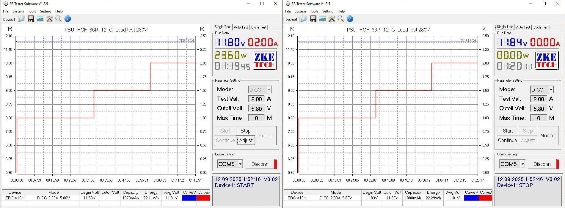
The temperatures are quite predictable. Here are the results at 1.5 and 2 A.
There isn't much to see at 1.5 A, but at 2 A you can see that the transformer is already at 100 degrees, while the output diode is almost at 120, which was entirely predictable.
In practice, this gives us a power supply rated for around 18–20 W continuous output, or 1.5 A.
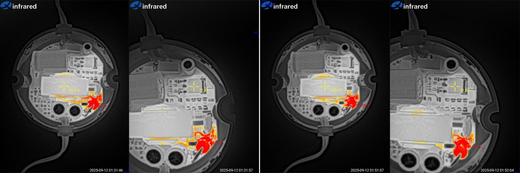
And now for the big brother—and it looks like a half-brother—the HCF-60R.
The layout is basically the same, but the case and circuit board are a little larger.
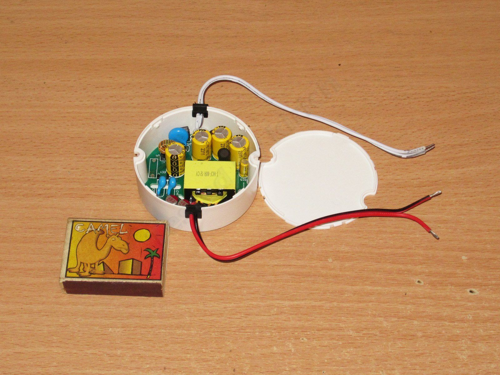
It's clear right from the start that this unit is considerably more complex: more capacitors, a larger transformer, and so on.
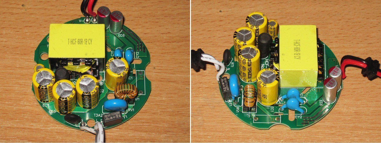
1. The input has a fuse, bridge rectifier, inductor, and varistor. There are no EMI suppression capacitors or thermistor.
2. The varistor is rated for a 560 V peak voltage, so it's essentially only there to protect against mains surges.
3. There are four 27 µF capacitors, which is more than enough for a 60 W power supply on our mains voltage, and also quite sufficient for 115–120 V.
4. There's an additional inductor in the input capacitor circuit to reduce ripple in that circuit.
5. There are two Y capacitors, which is quite rare. I've seen Mean Well units with two in series, but here they're connected differently: on the hot side, one goes to the positive rail of the high-voltage circuit and the other to the negative rail; on the cold side, both go to the output negative.
6. The output has a pair of 680 µF, 16 V polymer capacitors, which looks good to me.
The previous power supply had a completely bare underside of the circuit board; here it's the opposite, with most of the components mounted there.
I should point out the safety slots, as well as the relatively modern optocoupler in a long package.
And here's the main difference: this power supply is built around GaN-based chips, which came as a complete surprise to me. This controller is designed for power supplies rated at around 65 W.
The output has a component that looks like a typical diode array, but judging by the specs and my test results, I suspect it's a synchronous rectifier. Unfortunately, searching turned up no information about this component.
By the way, speaking of GaN and all that. I've got a few small power supplies from AliExpress at home, rated at 72 W: 12 V, 6 A and 24 V, 3 A. It turns out they have a lot in common with the one I'm reviewing: exactly four input capacitors, polymer capacitors on the output, and the same PWM controller. It'll be interesting to test these little guys :)
The total measured capacitance is 95 µF for the input capacitors and 1430 µF for the output capacitors, more than enough for 230 V mains and quite acceptable for 115–120 V.
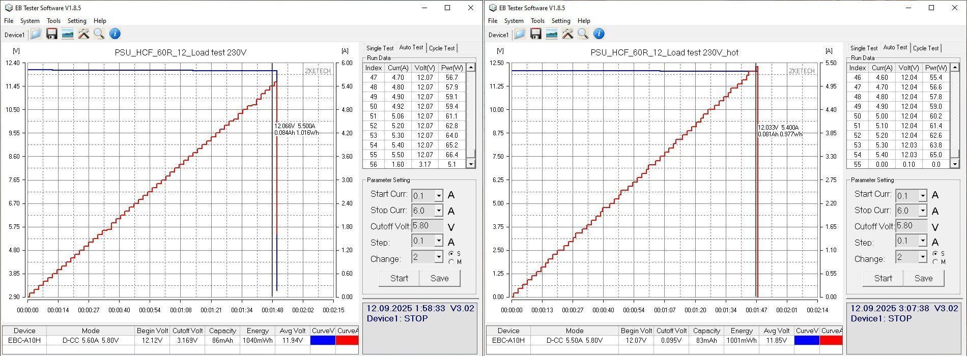
The protection is correctly set for the rated current of 5 A: 5.5–5.6 A when cold and 5.4–5.5 A when hot. As you can see, it's threshold-based: it shuts off the output under overload rather than reducing the voltage. Sometimes that matters.
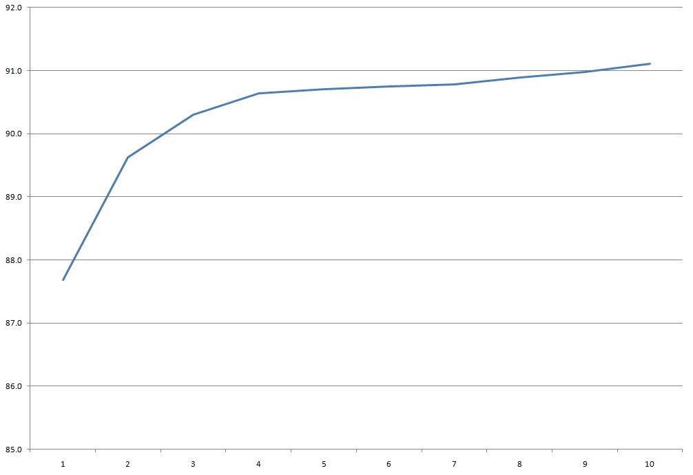
Efficiency from 0.5 to 5 A, in 0.5 A increments. Yes, the results are better here: 90–91% versus 85–86% for the previous unit. But if the output really does use a synchronous rectifier, efficiency could be even better.
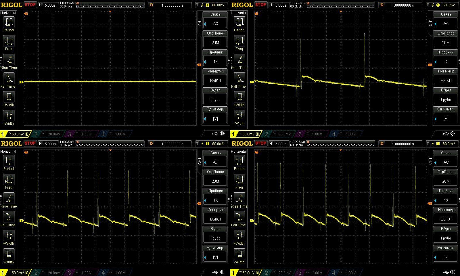
Ripple is lower here, thanks to the polymer capacitors. Results with no load and at currents of 1.5, 3, and 5 A.
I'd say it's all very good: the main ripple component is just 50 mV, but the spikes, with an amplitude of around 220 mV, gave me some pause. The value itself isn't particularly high, but the large difference from the main section is concerning.
It's also noticeable that the PWM controller adjusts the frequency over a fairly wide range.
At low frequency, everything is fine, both in terms of the full swing and the absence of 100 Hz ripple.
I ran the thermal test at currents of 2, 3, and 4 A. The power supply holds its voltage very well under load; the difference here is due only to the output wires. There's a slight negative effect from heating, but it's just 40 mV.
And here are the temperatures. Below are photos taken after the 3 A and 4 A tests.
At 3 A, everything is excellent. At 4 A, temperatures are still acceptable overall: 90 degrees on the transformer and 103 on the PWM controller. But the output diode temperature concerned me: 111 degrees.
In my opinion, this power supply's continuous current rating is around 3.5–4 A; I wouldn't run it at a higher load for extended periods.
Conclusions.
I wrote above that these power supplies are like brothers, but only half-brothers. The point is that the two units are actually quite different in terms of circuit design, components, and specifications. The main things they have in common are the same form factor and the fact that neither can deliver its rated power continuously. Actually, that's not quite true: neither model raises any concerns in terms of electrical safety, which, incidentally, is far from always the case with Chinese power supplies.
Still, if we look at the shortfall as a percentage, the 60 W model comes noticeably closer to its rated 60 W and can actually deliver around 45 W continuously.
Overall, the first one is suitable for powering low-power loads. In theory, you could install it in a wall box, but only if you reduce the load. I liked the second one much more: it has modern components and delivers quite good results in terms of ripple and heat.
That's all for now. I hope you found this information useful, and thanks again to Vitaly for providing these samples of Chinese industry for testing :)
This model is included in the summary table: Comparison of power supplies: ripple, efficiency, and temperature rise
The figures from this review are in the measurement database: Power supplies
Calculate manuallyAll calculators
Discounted products
You may be interested in



Discounted products
Support the project
All the content on the site and the advice are free, but we’d be grateful for your support of the project and the channel!
Comments2
Discuss on the forumHave a question or some experience to share? Discuss the article with the author and readers: the forum is a convenient place to share schematics and photos.
Go to the forumOnly registered readers can comment. It takes a minute to sign up, and you can log in with the same account you use on the forum.
Log inRegister
Comments are published in their original language.