
Slim 12 V HCA and HCF series power supplies, 18–100 W
You can find all sorts of things on the power supply market, but I haven’t come across power supplies in quite this form before. I’m not saying this is a good design; it just exists, so it’s worth taking a closer look and testing it.
A reminder: to keep up with new posts on the blog, I recommend following me on Instagram. I’ll post notifications about every new article there, and might also write about something interesting now and then - link to the account
You can also subscribe to updates and new articles on the Telegram channel - https://t.me/KirichBlog
I’ve already published a review of the HCF series power supplies, but those were round, while these are “thinner, but longer.”
I won’t include links to them, since these are test units sent over to check what a particular factory actually makes and whether it’s worth doing business with them.
The first thing that stands out is the unusual form factor: these power supplies really are thin. Though I’m not even sure what to call them, since “thin” refers to thickness, and they’re narrow as well.
There are 10 power supplies in all. Two of them look more conventional, although they belong to the same series; I just decided not to give them their own article.
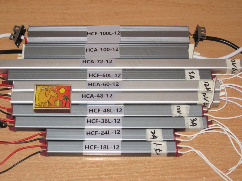
I’ve grouped all the power supplies into pairs, since most differ mainly in power rating. At least one pair is shown together simply “to keep the paperwork in order.”
I’ll start with the two smallest models, rated at 18 and 24 W, or 1.5 and 2 A, respectively.
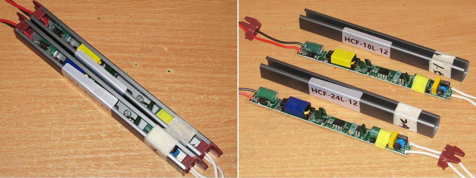
The cases are 175/195 mm long, with a 17 × 14 mm cross-section. The wires have silicone insulation.
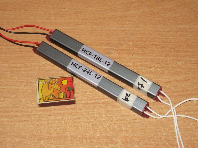
Even I’m struggling to come up with a name for this kind of case design. On the one hand, it is technically a case, but it has a fairly wide gap running its entire length, which is not very safe. That’s a fact too. And the case appears to be made of steel.
There’s a board running the full length inside. It has an insulating sheet, but only underneath the board. I don’t know, but this design makes me uneasy.
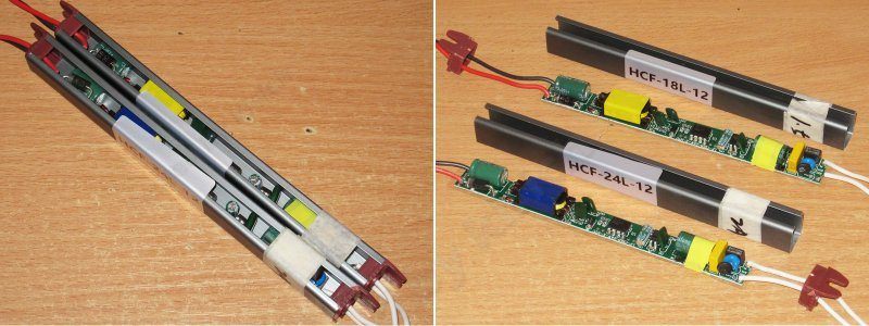
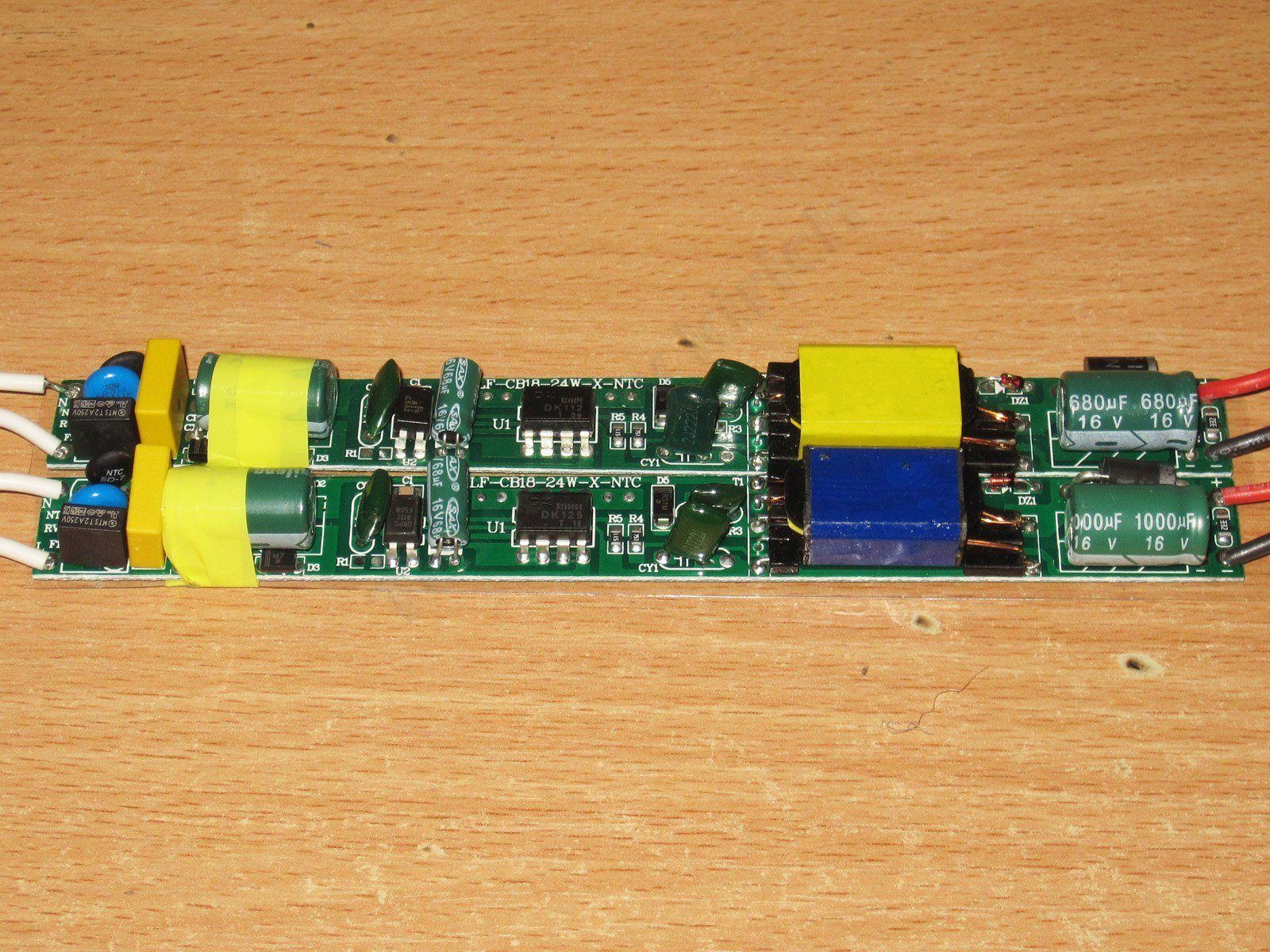
The layout is relatively spacious, but the board is so narrow that there are a few things to complain about. By the way, the PCB material in most of these power supplies is very thin. I didn’t measure it, but it’s definitely under 1 mm, so the boards in the longer models literally bend in your hands.
Visually, the boards are identical, except perhaps for the color of the transformers.
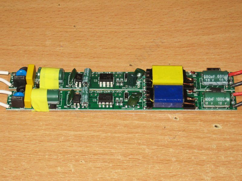
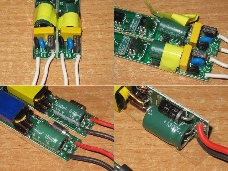
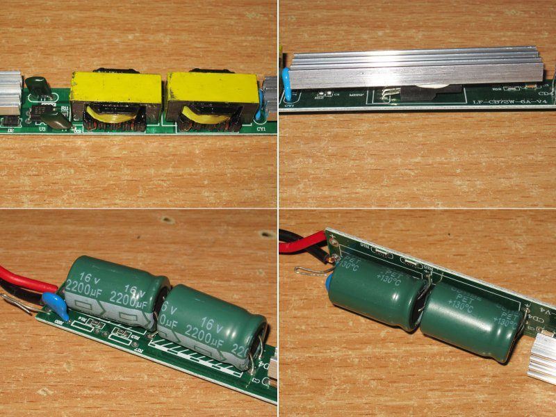
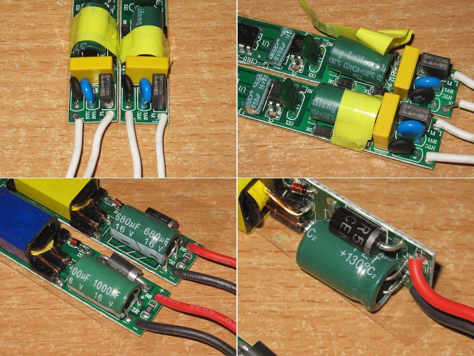
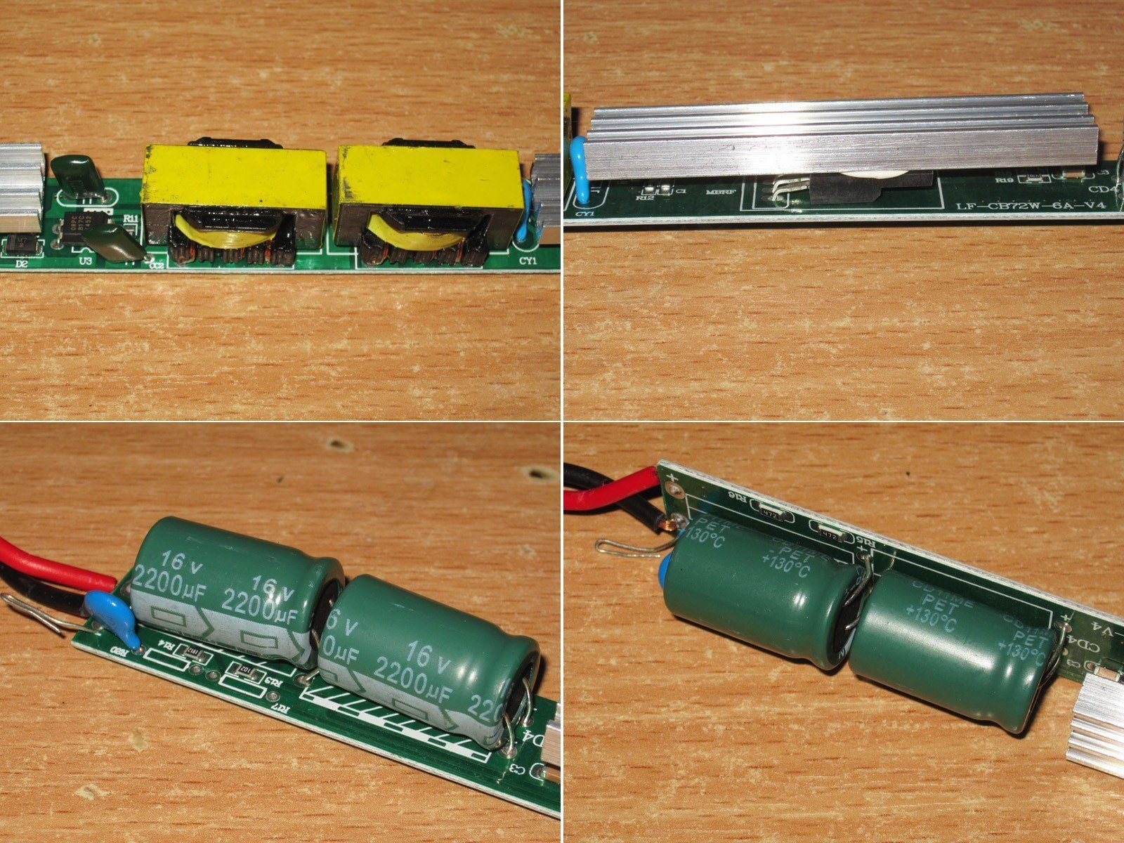
There’s no input choke, but there is an X capacitor, a thermistor, a proper fuse, and even a varistor rated, I think, for 510 V peak.
The input capacitors are 10 and 15 µF, depending on the power rating, but what surprised me is that they’re rated for 130°C!
The output capacitors also differ: 680 µF in the 18 W model and 1000 µF in the 24 W model. They’re also rated for 130°C.
I can’t say for sure whether these capacitors are really rated for that temperature or whether it’s just a nice-looking label on the heat-shrink sleeve. But I can say this: I’ve more often come across capacitors rated for 125°C. They were marketed as long-life, but not low-impedance. They’re perfectly suitable as input capacitors, but not always as output capacitors.
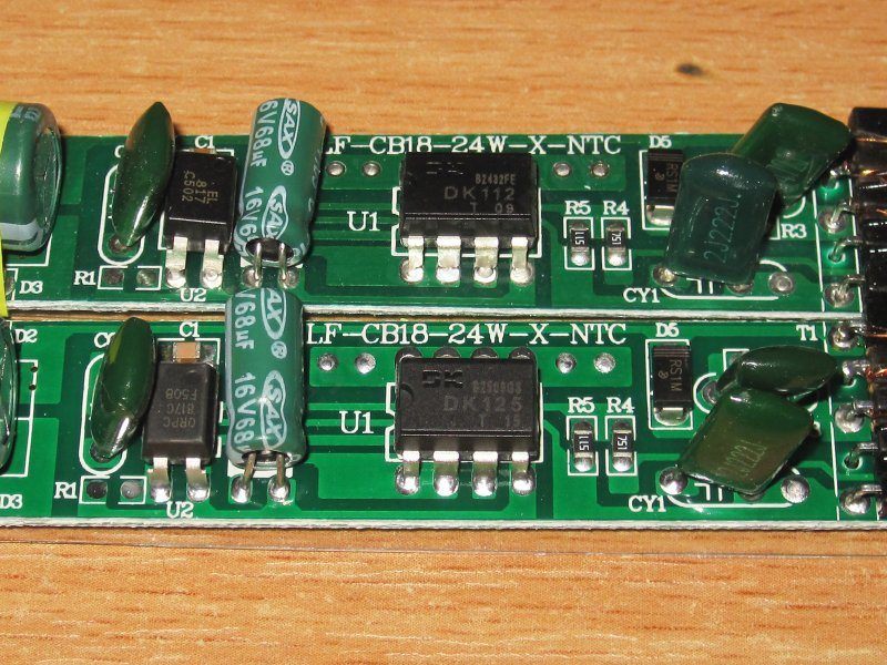
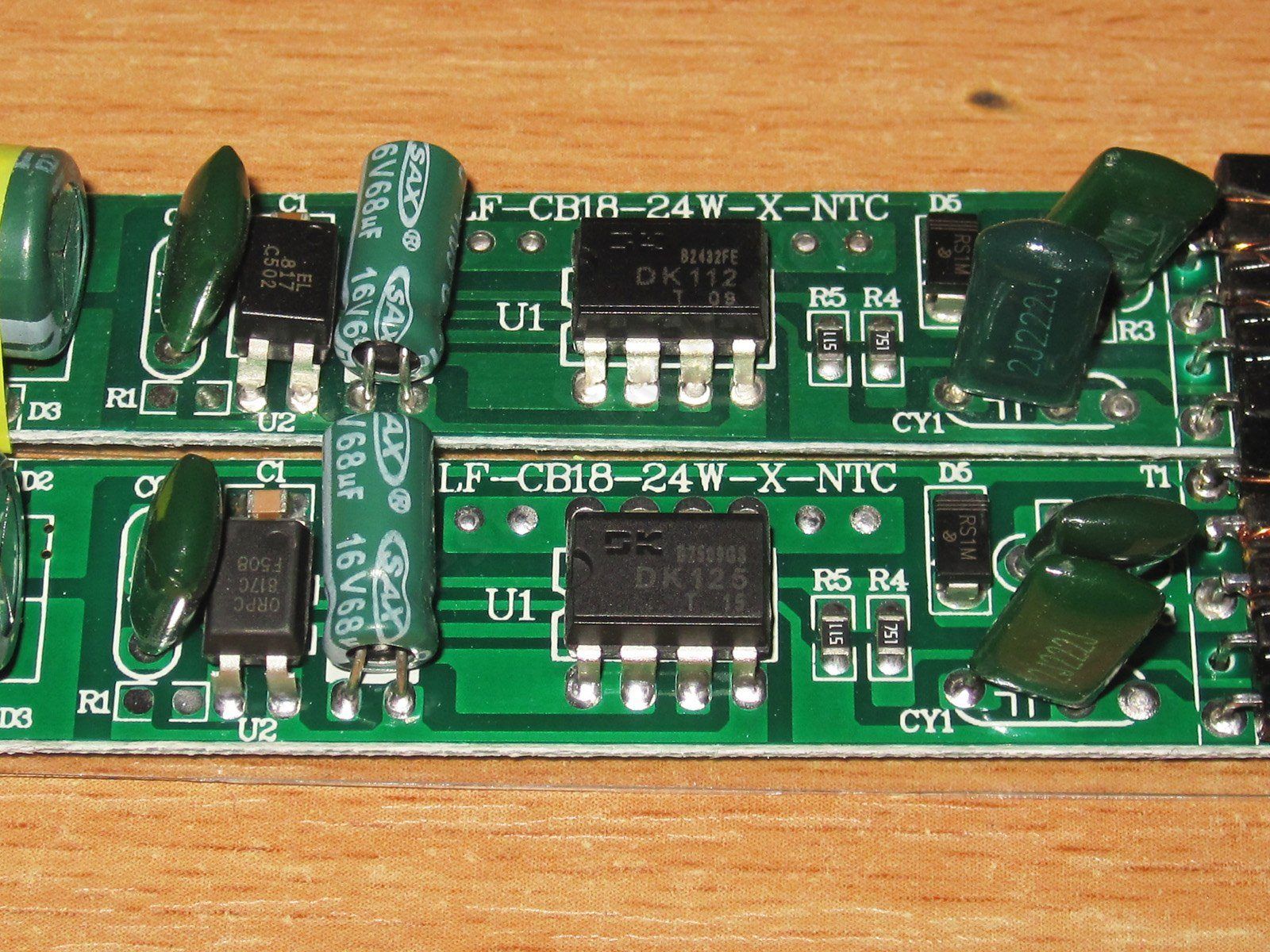
They use a fairly decent integrated PWM controller: the 18 W model has a DK112, while the 24 W model has a DK125. There’s a catch here: according to the datasheets, the first is rated for 12/15 W and the second for 24 W, so the first one will be overloaded.
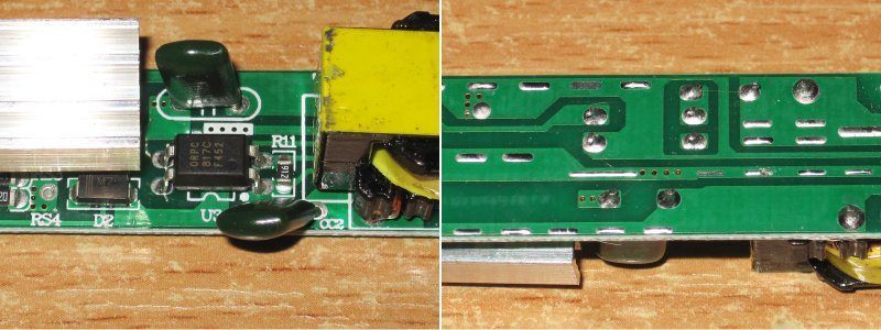
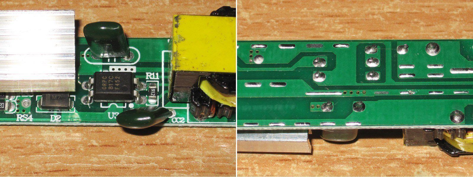
In principle, that’s not a problem, since these controllers have built-in thermal protection and should simply shut down in the worst case. The real problem is that the feedback optocoupler is on the hot side, a long way from the rest of the circuit, so the “cold-side” traces run very close to the “hot-side” traces.
Grounding the output could solve this problem, but there’s another catch: although the board marks the live input terminal, and the fuse is installed on that input, the input wires themselves aren’t marked. With these models, you can more or less peer through the gap to see which wire goes where, but that’s a pretty clumsy solution...
The point is that if you ground the output, the input polarity must be such that the fuse is on the live wire. If there are no markings and you can’t connect the power supply with 100% certainty, the right thing to do is install two fuses.
So this power supply should only be used in designs where, first, the power supply itself isn’t freely accessible, and second, neither the input nor output live parts are accessible. Such designs do exist, but they’re rather specialized.
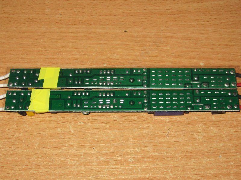
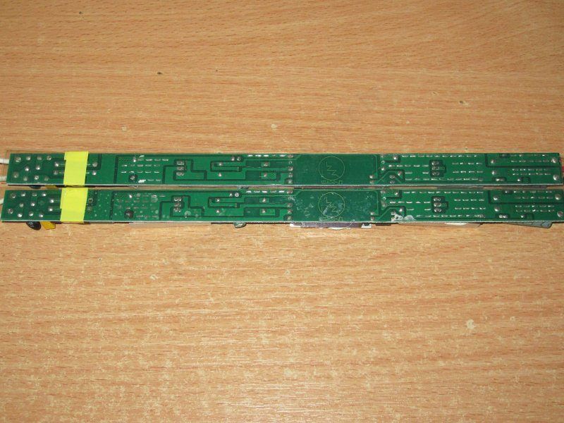
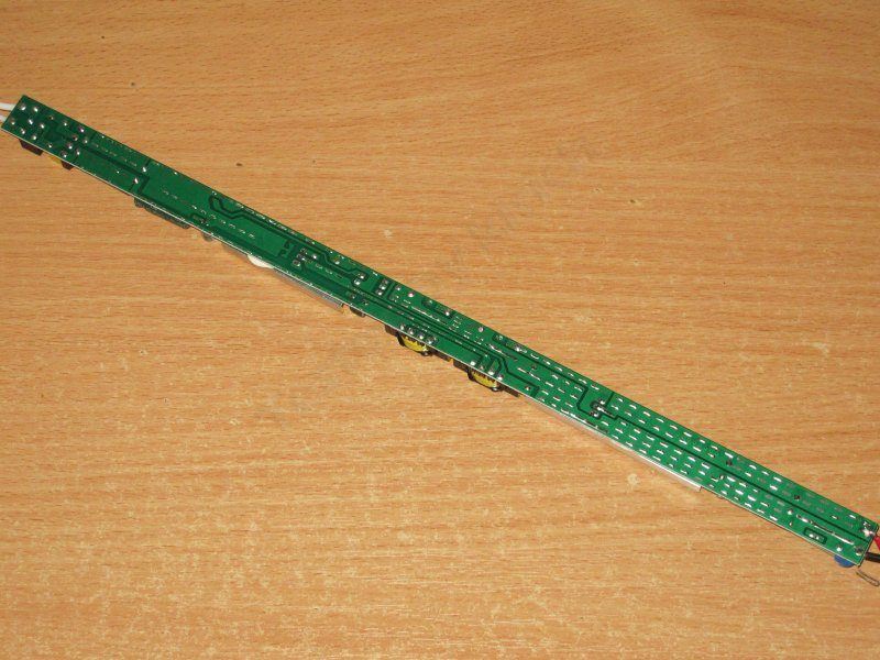
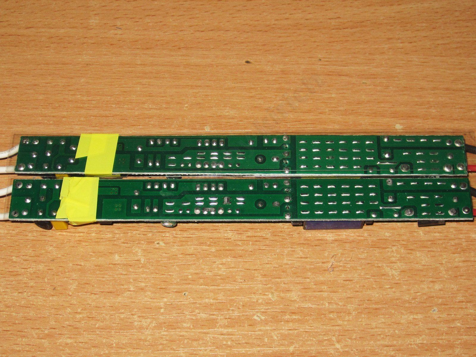
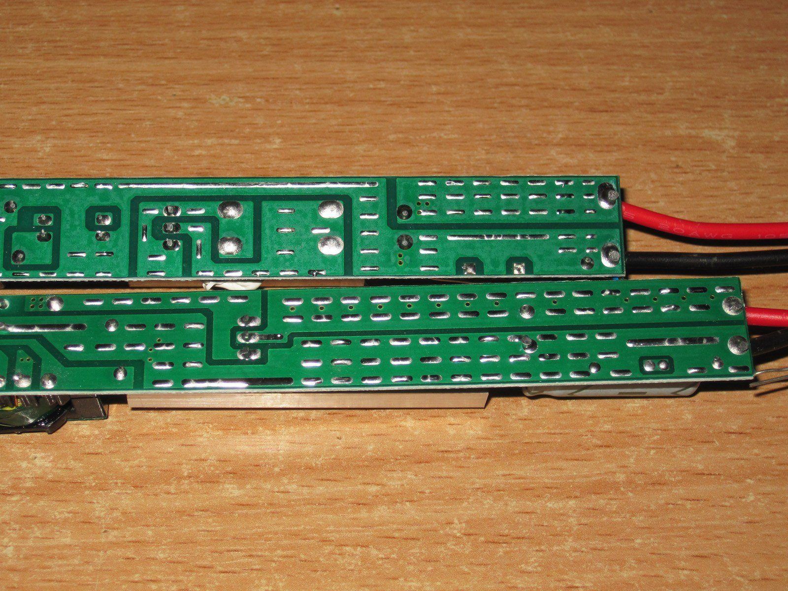
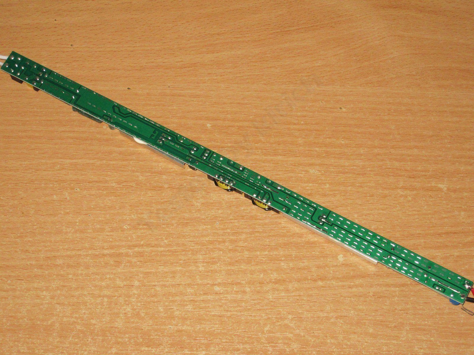
The underside of the PCB also shows that one of the copper pours connected to the output is very close to the transformer’s input pins. Although the large copper pour itself doesn't serve much purpose here, since there is a narrow section near the output diode—the very component the pour is supposed to help cool.
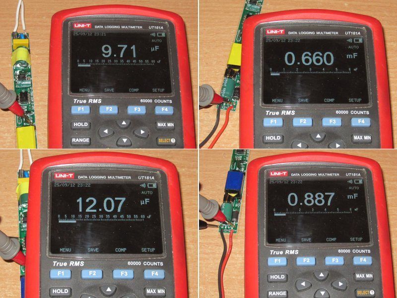
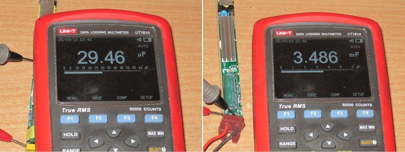
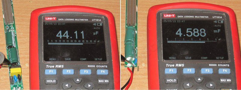
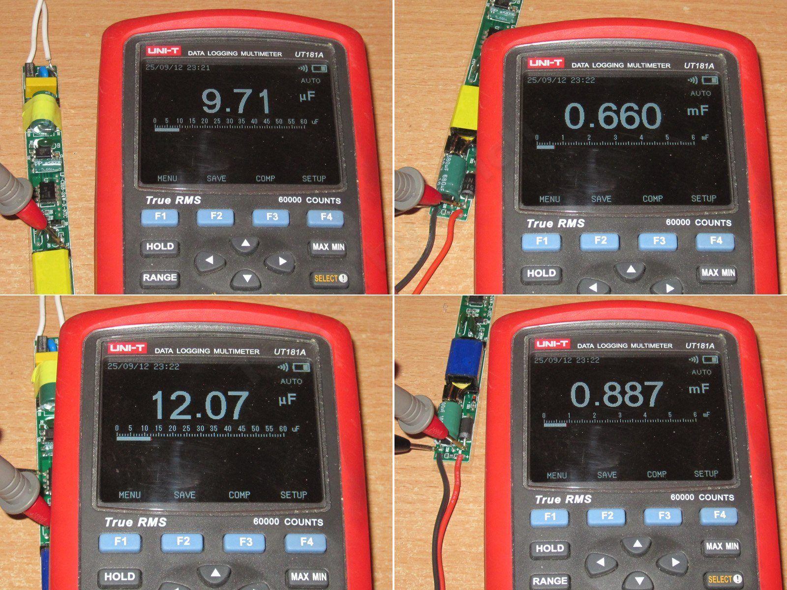
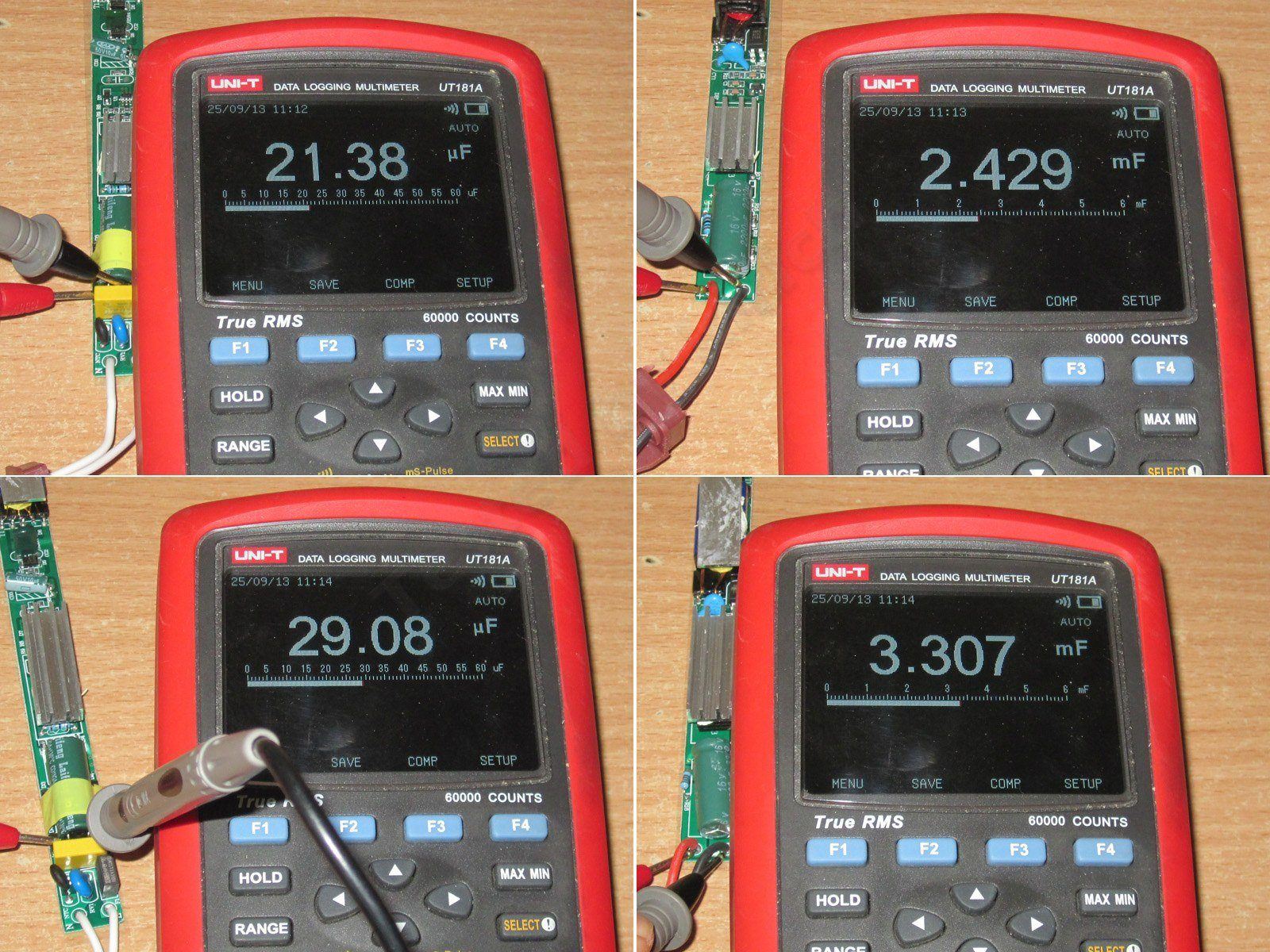
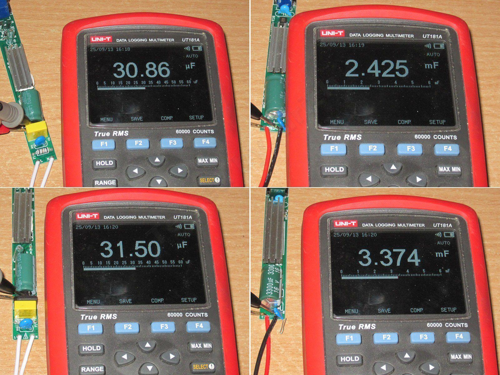
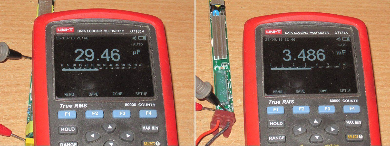
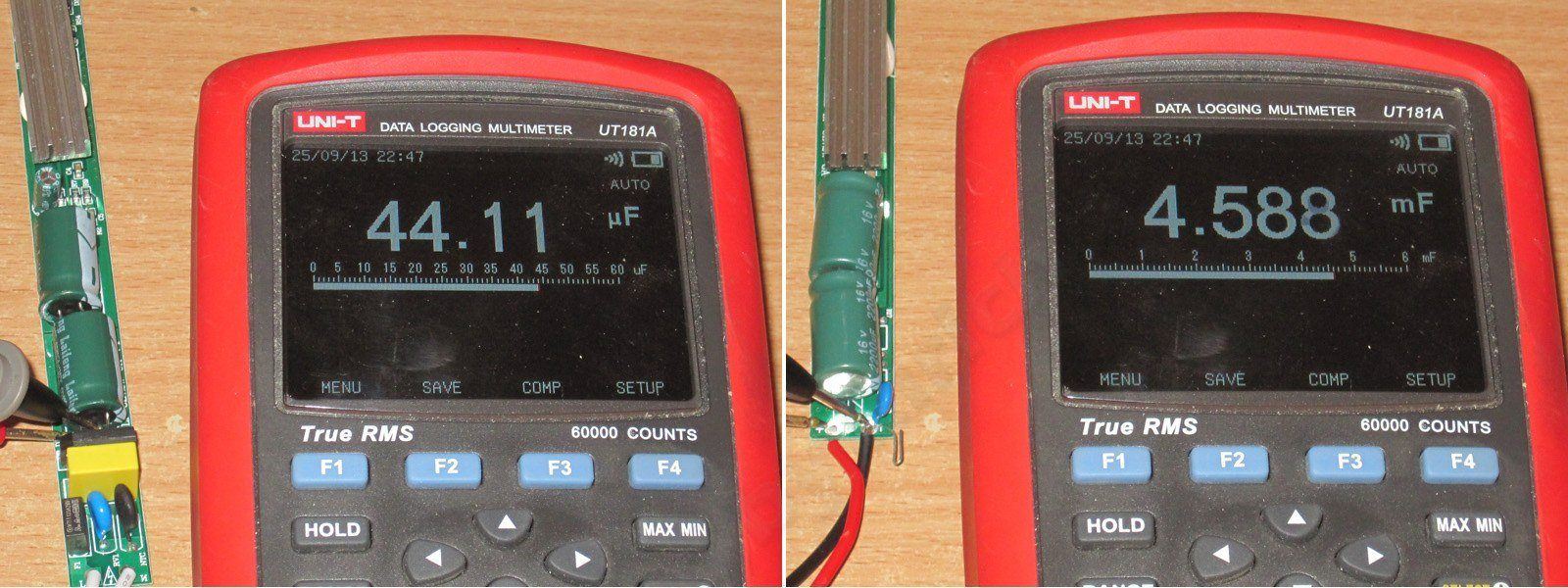
Measured capacitance of the input and output capacitors for the first and second power supplies, respectively. The input capacitance is a little on the low side. It should be fine at 230 V, but at 115 V the PWM controller will have a harder time.
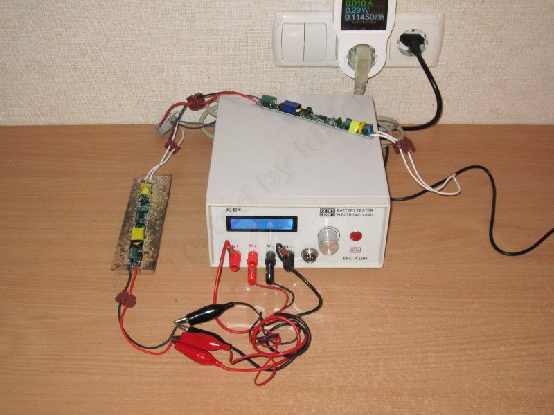
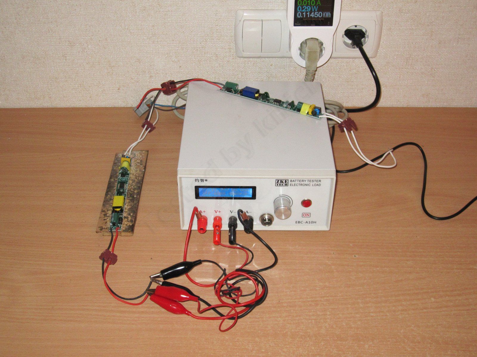
As usual, I use an EBC-A10H battery tester to check low-power supplies. For the efficiency test, I used an electronic load based on a CL24 board.
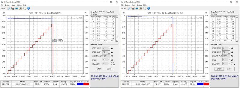
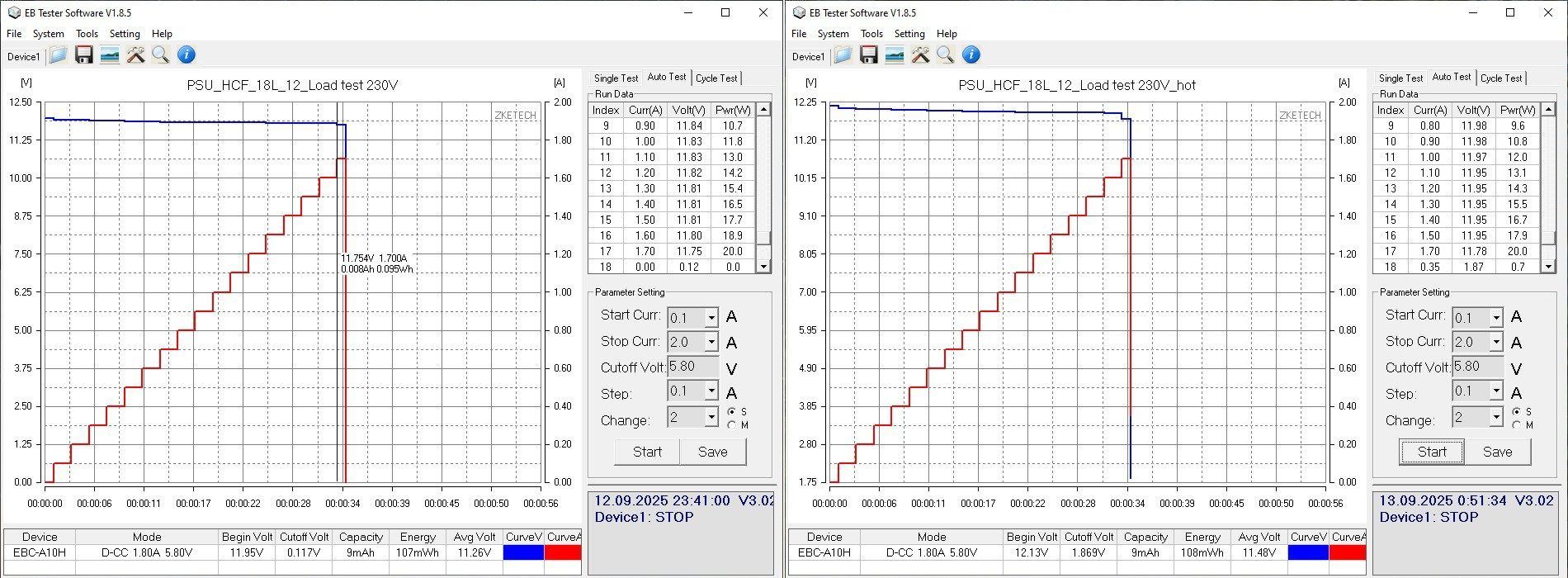
The 18 W model's protection trips at 1.7–1.8 A, whether the supply is cold or hot. Output voltage stability is quite good.
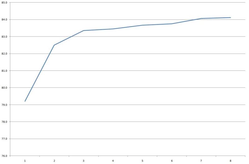
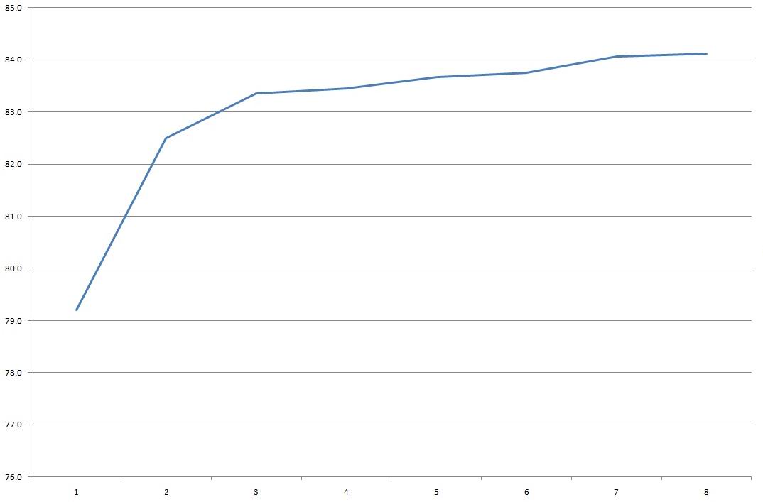
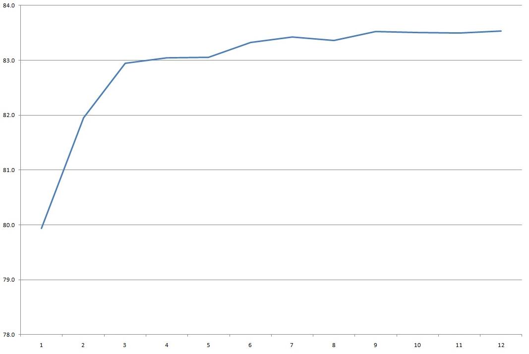
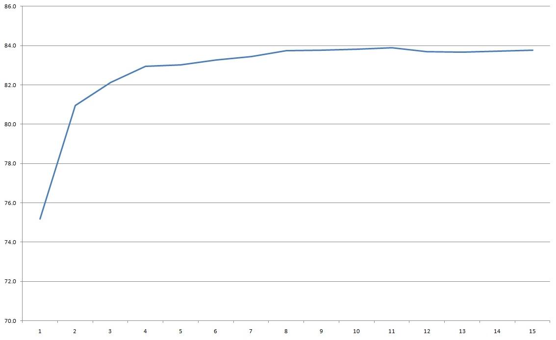
Efficiency is 83–84%, which is pretty typical. The scale at the bottom is in 0.2 A increments.
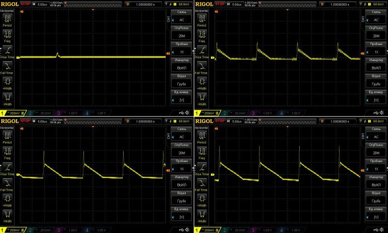
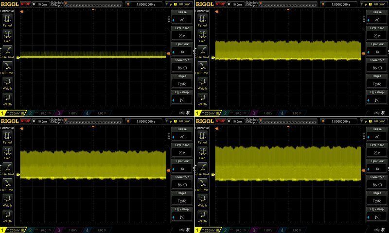
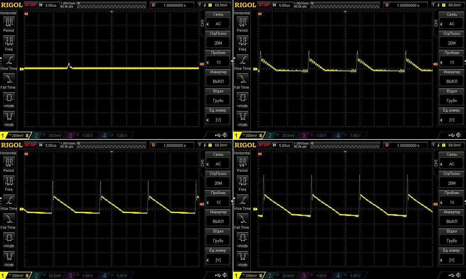
Ripple with no load and at 6, 12, and 18 W. Pretty much as expected: at maximum power, most of it is around 300 mV. That's probably tolerable, and should be fine for undemanding applications such as LED lighting.
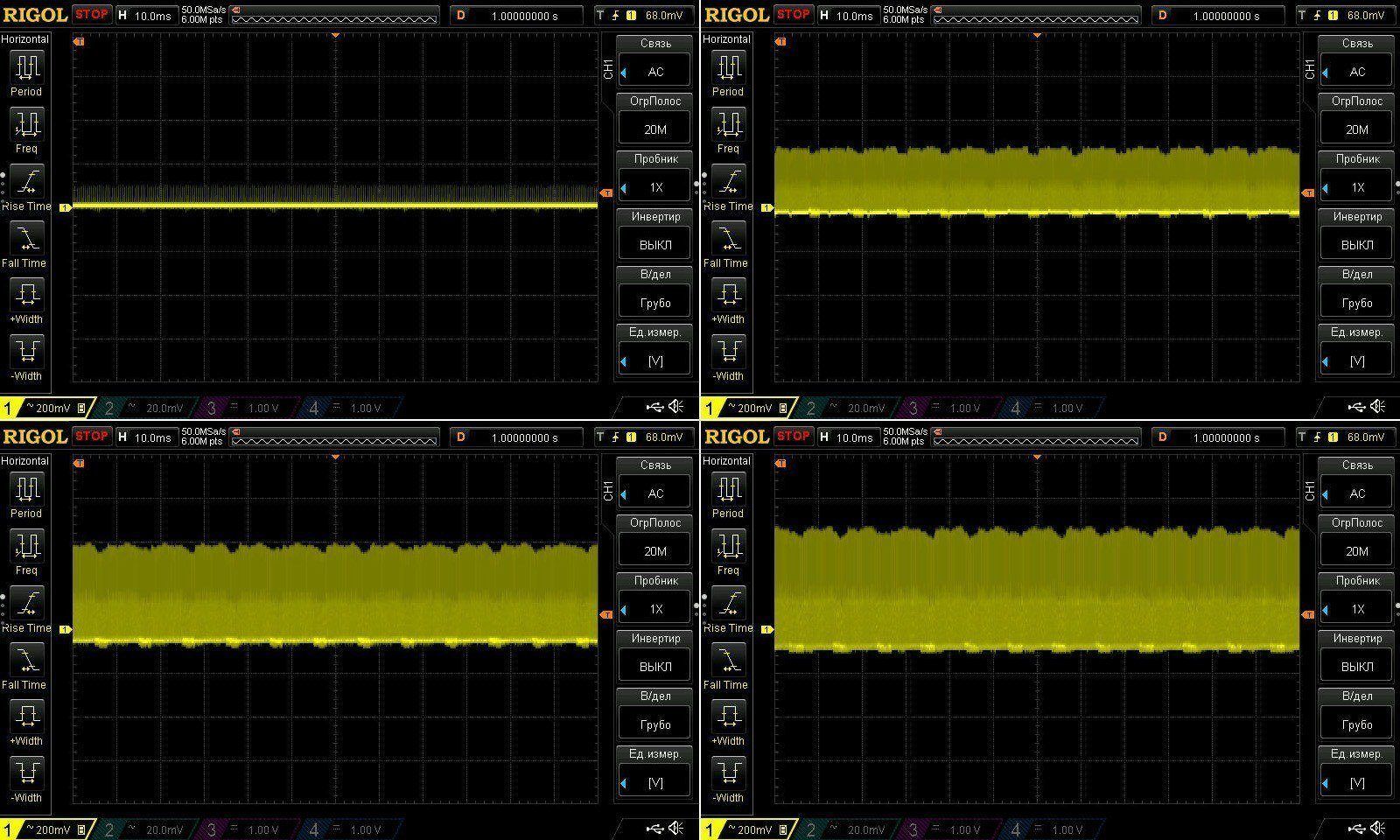
The low-frequency ripple is actually quite good; there's practically no 100 Hz component.
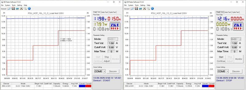
I checked the temperature rise at 0.5, 1, and 1.5 A.
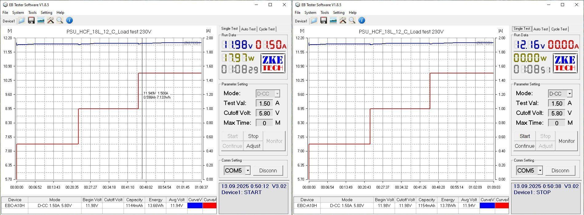
The power supply's output voltage has a slight positive temperature coefficient. It started at 11.98 V when cold and ended at the same 11.98 V after warming up, ultimately compensating for the voltage drop in the wires. The power supply itself dropped by 50 mV as the load changed from 0 to 100%.
A note: here and below, unless otherwise specified, measurements were taken at the output wires, which slightly affects the output voltage under load. When measuring efficiency, I monitored the voltage directly at the power supply output, so I could see how well it actually maintains its output voltage.
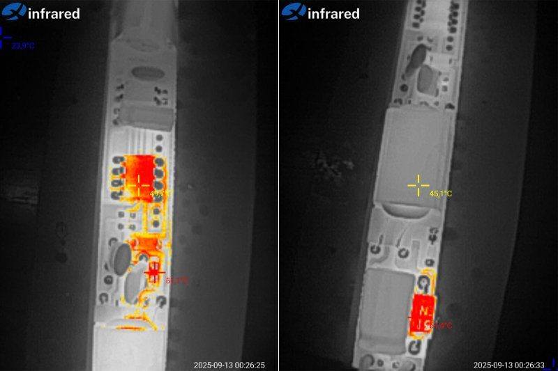
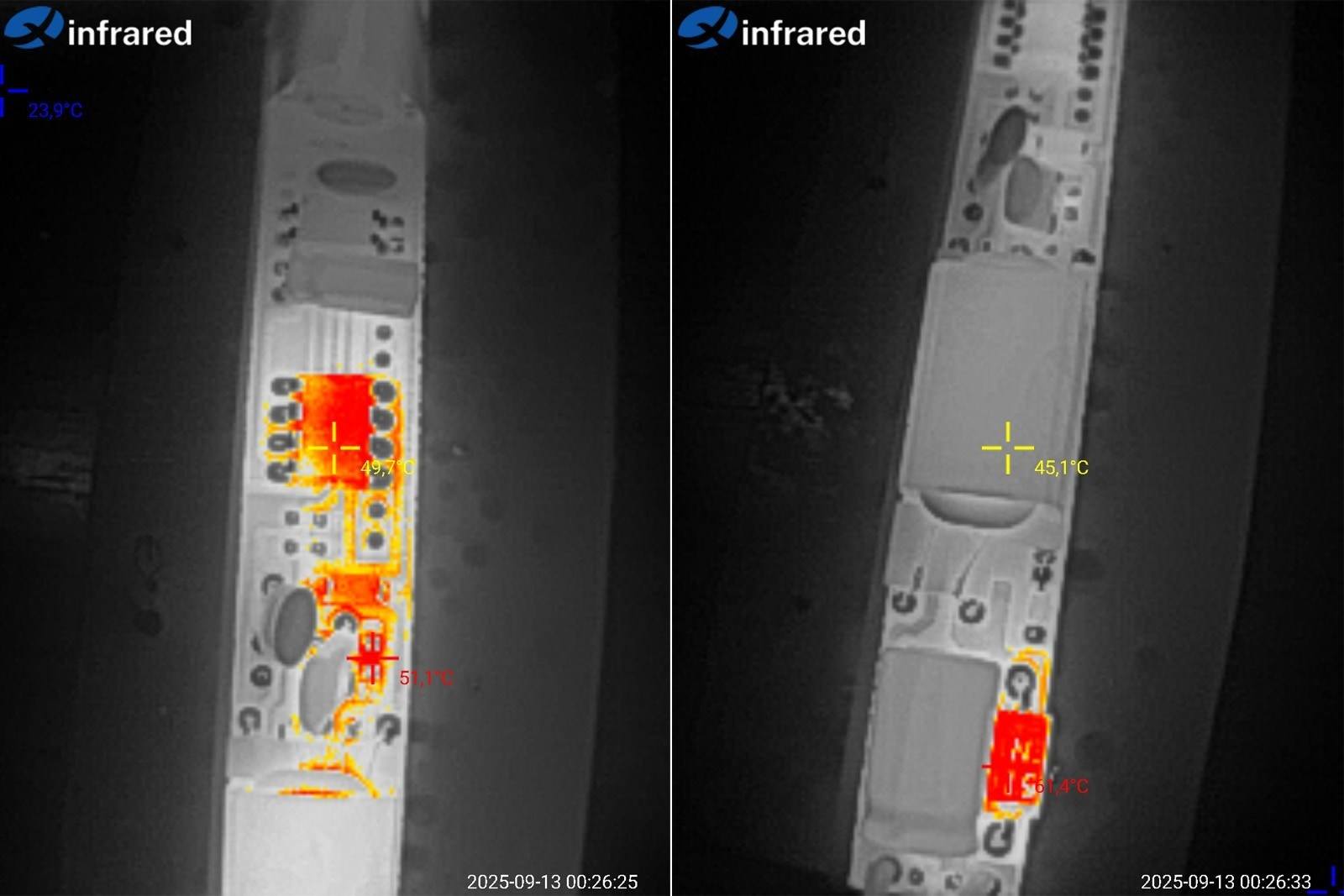
At 1 A, temperatures were well within the normal range: the PWM controller was at 50°C, the transformer at 45°C, and the diode at 61°C.
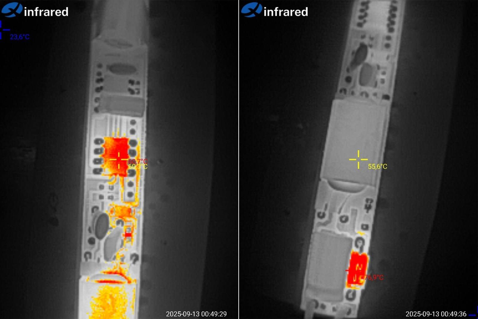
Again, because it's difficult to measure temperatures with the unit closed up, I had to measure the bare board lying on the table. I expect temperatures to be higher once the board is installed in the enclosure. The point is that in similar power supplies filled with potting compound, a significant amount of heat is transferred to the enclosure, improving cooling. Here, by contrast, although the enclosure is metal, heat reaches it through the air.
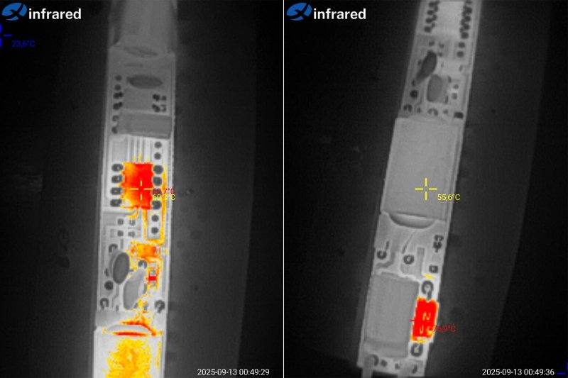
At 18 W, everything also worked well: the PWM controller was at 61°C, the transformer at 55°C, and the diode at 77°C. There's even a decent amount of headroom.
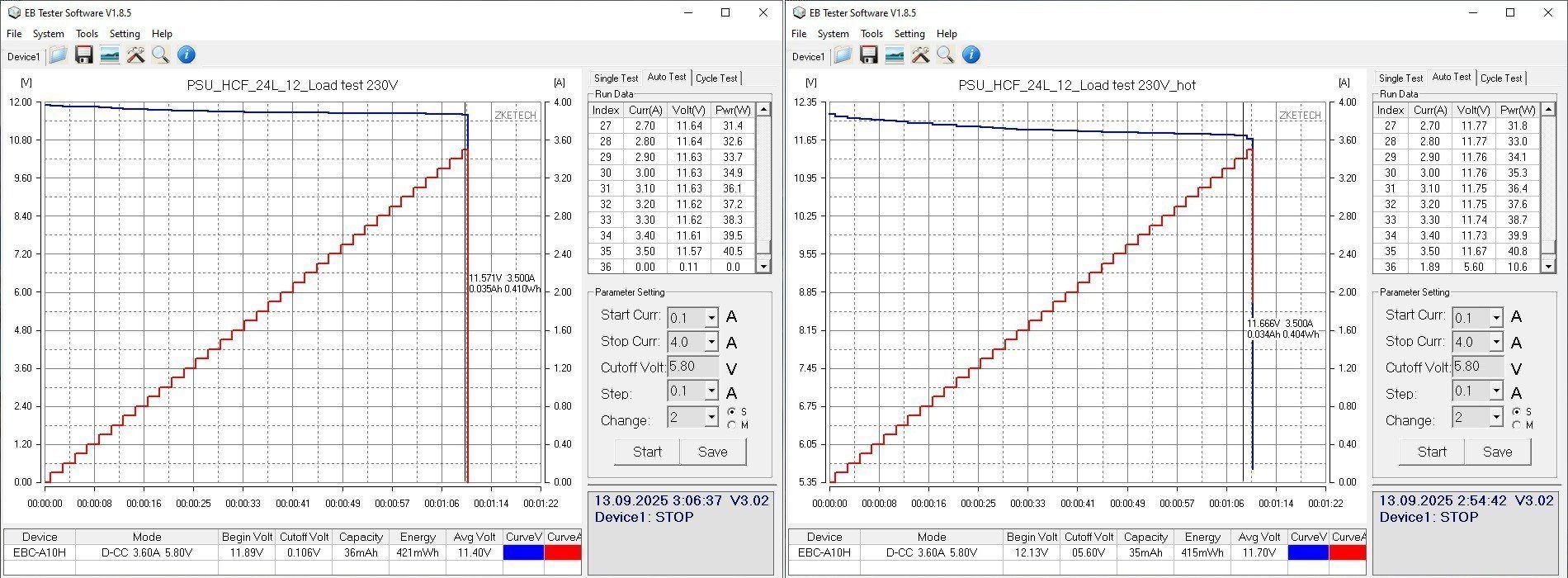
The 24 W model, which also has a 24 W controller, shut down at 3.5 A. That's rather crude given its stated maximum of 2 A. But as I mentioned, the chip has thermal protection, so there's no real cause for concern. In my own experience, I've only come across one power supply using this PWM controller that failed.
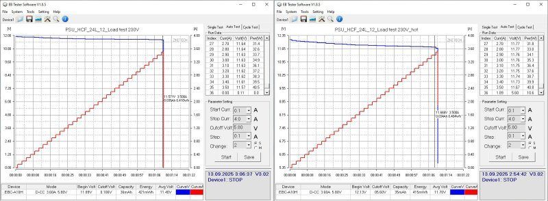
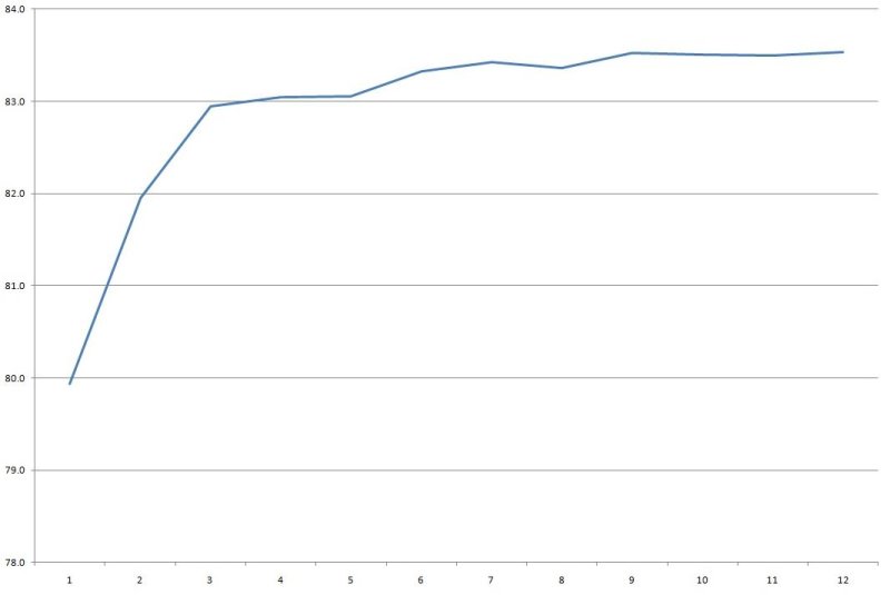
Efficiency is slightly higher, probably thanks to the higher-capacitance input capacitor and the PWM controller and transistor, which have lower resistance.
The scale at the bottom is in 0.2 A increments.
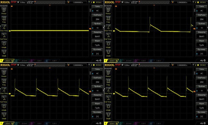
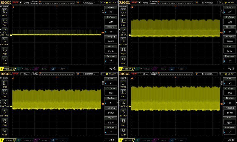
The high- and low-frequency ripple is almost identical to that of the previous power supply, so the recommendations for use are the same. I tested it with no load and at 0.7, 1.4, and 2.1 A.
I checked the temperature rise at 1, 1.5, 2, and 2.5 A, so even with a noticeable overload. It behaves just like the previous model: the graph shows steps where the voltage sags under load, then rises slightly as the unit warms up.
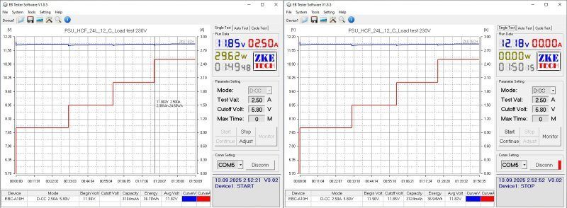
Temperatures at load currents of 2 and 2.5 A.
At 2 A (100% power), everything is quite normal: the transformer is at 77°C, the PWM controller at 67°C, and the diode at around 100°C.
At 2.5 A, things got a little worse: the transformer was at 92°C, the PWM controller at 78°C, and the diode at 117°C. The only real concern is the diode temperature; the other components still have a little headroom.
Overall, I think the temperatures are fine here, with a little headroom for installation in an enclosure and for higher ambient temperatures.
Next up are the HCF-36L and HCF-48L models, rated at 36 and 48 W, or 3 and 4 A, respectively.
Length: 263/283 mm; cross-section is the same as the previous models, 17 × 14 mm. Silicone-insulated wires; essentially, compared with the previous ones, the only visible difference is their length.
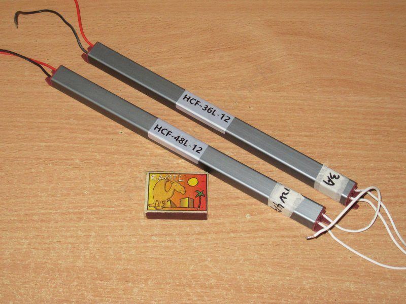
The design is absolutely identical to the previous models. In fact, these power supplies are almost the same.
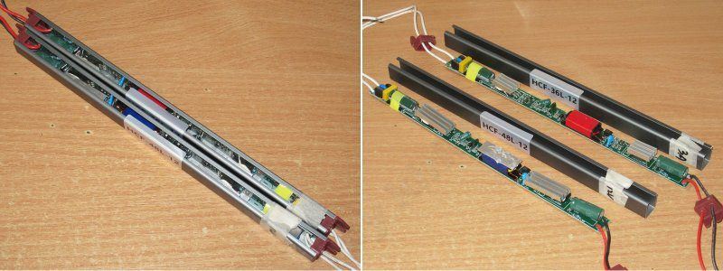
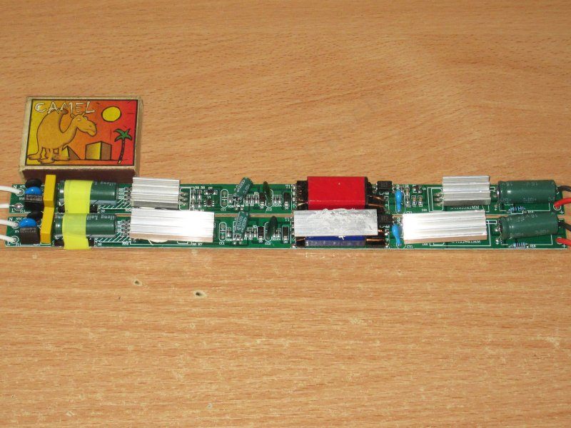
Visually, the boards differ in their larger heatsinks and the aluminum plate on the transformer in the 48 W version.
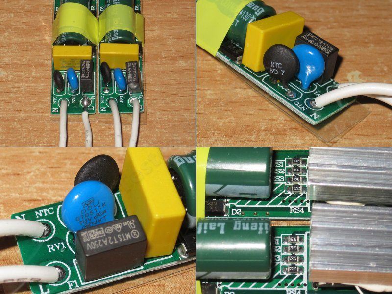
The input has an X capacitor, thermistor, varistor, and fuse, but no inductor.
I found one more difference: the current-sense shunt resistance is different. The 36 W model has 2.2, 2.2, 2.4, and 2.4 Ω resistors, while all four in the 48 W model are 2.2 Ω, which gives it a slightly higher protection trip current.
The transistors and diodes could theoretically be different too, but for some reason I seriously doubt it.
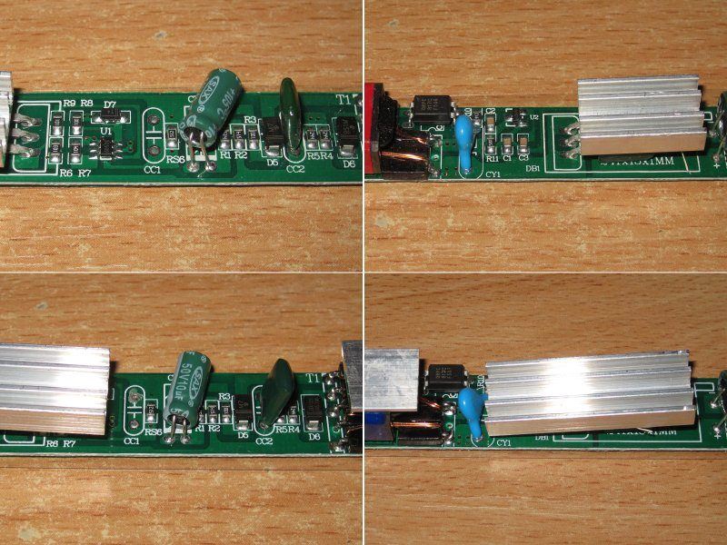
It uses a PWM controller marked 30509; in the 48 W version, it is simply hidden under the heatsink. The optocoupler is now in the right place.
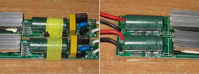
The input capacitors are 22 and 33 µF, but interestingly, they are almost the same length. The output capacitors are 2200 and 3300 µF for the 36 and 48 W versions, respectively.
These also use capacitors rated for 130 degrees.
The PCB layout here isn't ideal, but it's noticeably better than on the previous model.
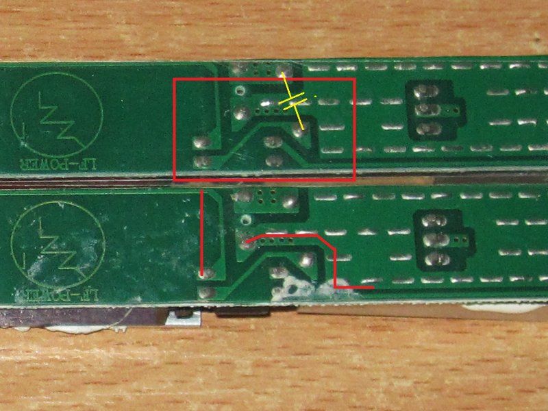
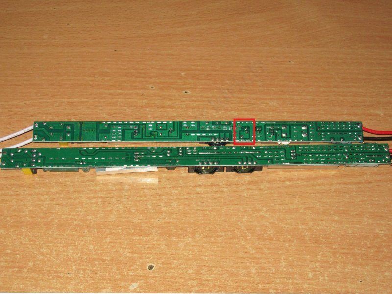
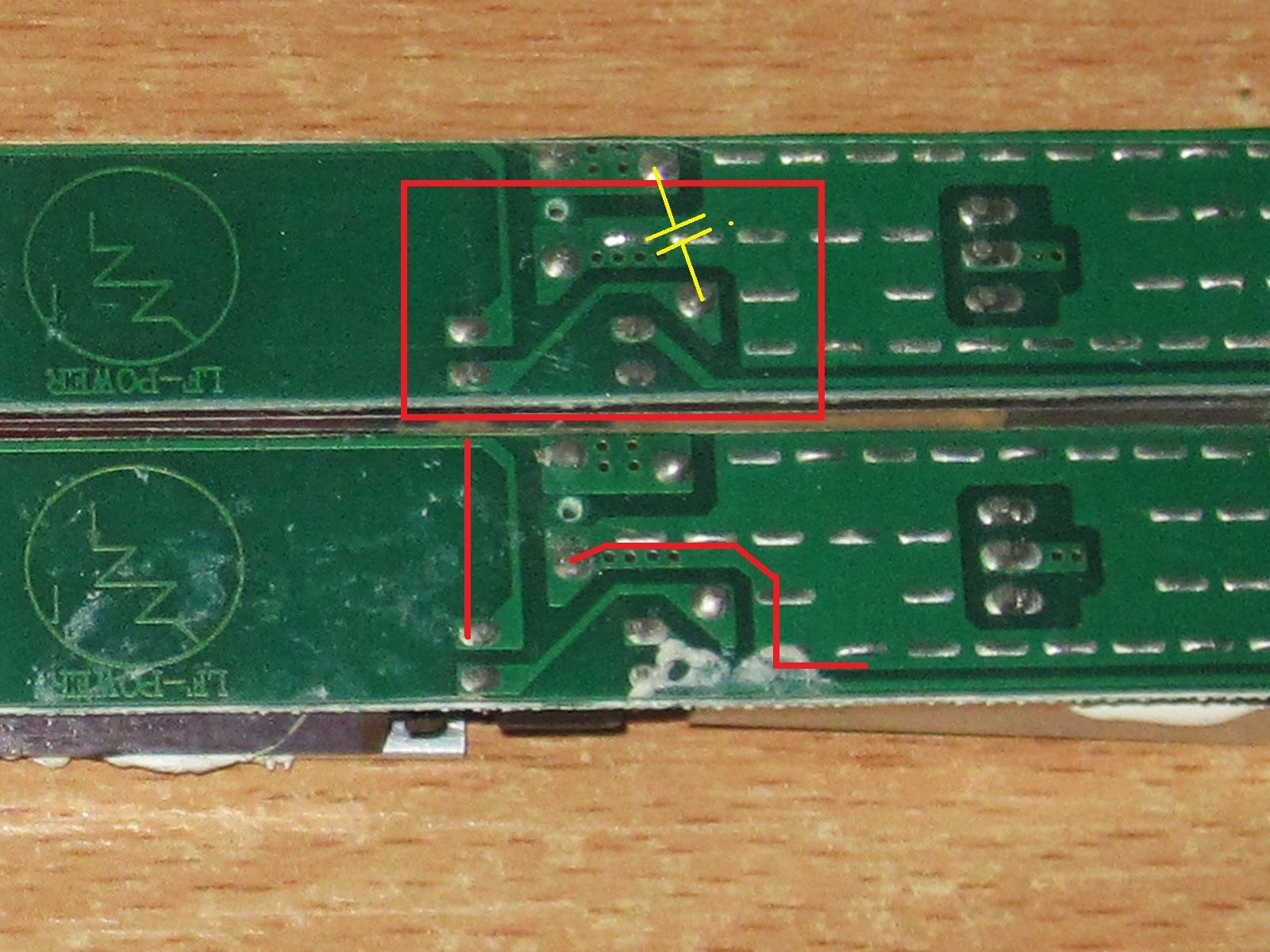
The thing is, the clearances are still small. The photo shows the Y capacitor, with the optocoupler pins below it.
I think that if the trace layout were changed slightly, as marked in red on the lower board, and one of the traces to the optocoupler LED were routed on the top side, things would be not exactly good, but noticeably better than they are now.
Overall, my recommendations for this model are much the same as for the previous one: either prevent contact with the output wires (by using a fully enclosed case), or ground the output, making sure the input is correctly phased. Or do both.
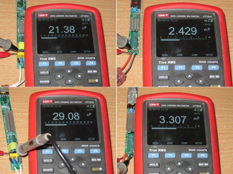
Input and output capacitance for the 36 and 48 W power supplies, respectively.
I have no concerns about the output capacitors, but the input capacitance is a little low. As before, it's fine for 230 V, but not enough for 115 V.
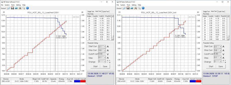
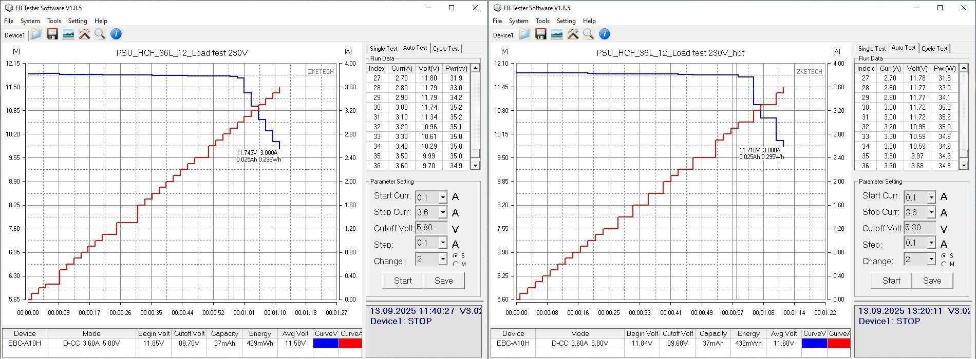
The protection trips at around 3 A, regardless of the power supply's temperature. In other words, the protection threshold is set very close to the limit here; perhaps that's a good thing. The protection is gradual, though: under overload, the output doesn't shut off immediately, but the voltage simply drops. Personally, I like this approach less, but a lot depends on the type of load.
The output voltage is very stable. Ignoring the voltage drop across the wires, the difference was 30 mV.
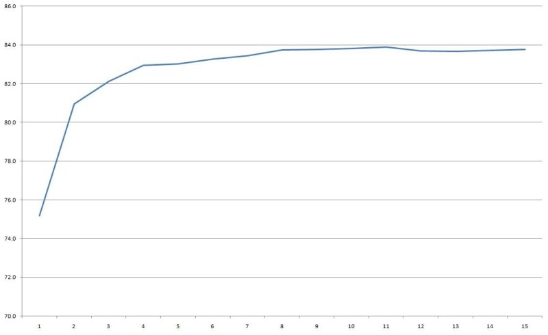
Efficiency is 83–84%; the scale at the bottom is in 0.2 A increments.
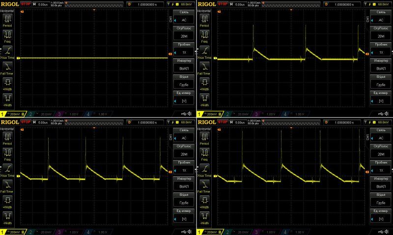
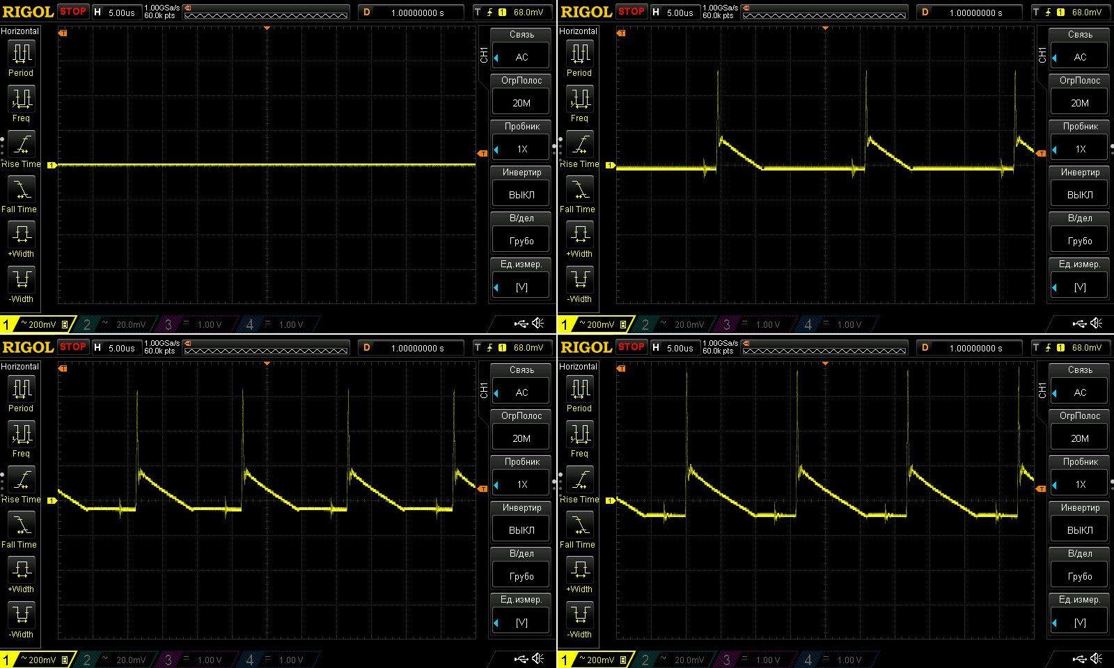
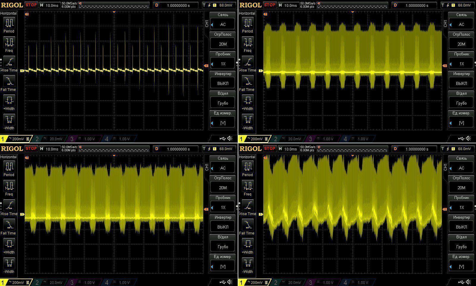
High-frequency ripple is around 300 mV at maximum current. Measurements were taken with no load and at currents of 1, 2, and 3 A. There are spikes, but they are usually easy to suppress with the wires to the load.
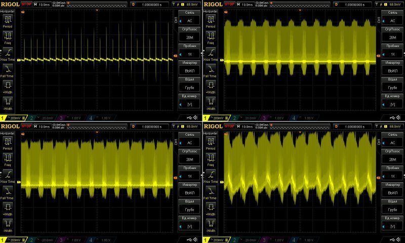
At low frequencies, things looked somewhat worse, with noticeable spikes at 100 Hz.
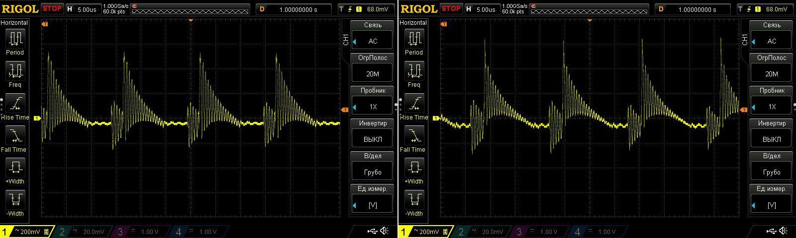
It also turned out that this power supply generates a lot of interference. I could literally hear it through the speakers of the computer the electronic load was connected to.
And at times, the high-frequency ripple waveform looked pretty ugly, too... It felt like the circuit was going into some kind of self-oscillation.
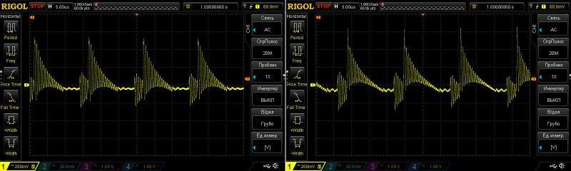
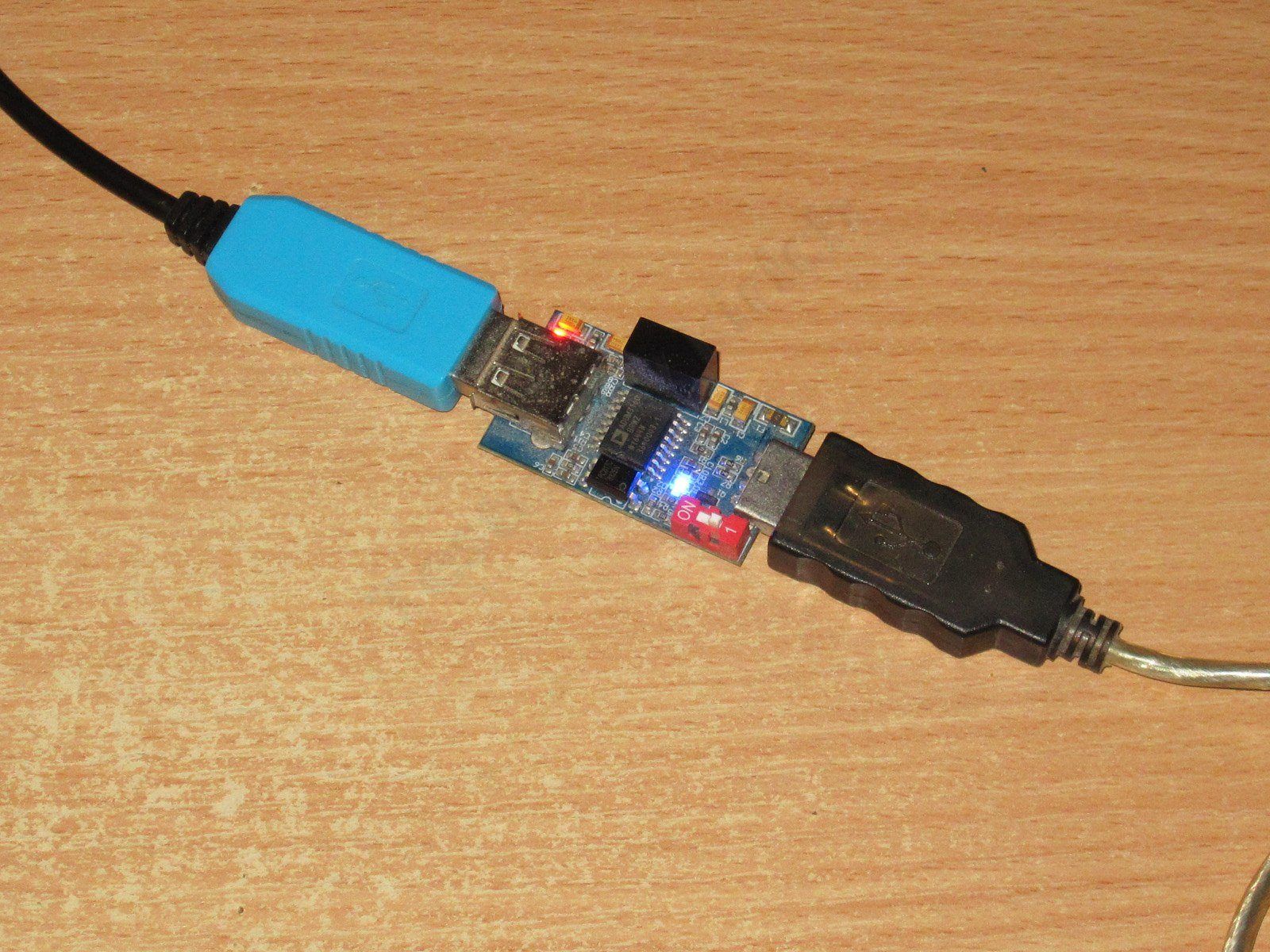
The ripple even affected the connection to the PC. In the screenshot above, you can see that the load wasn't increasing the current very evenly.
At first I couldn't figure out why this was happening. Then I realized that the high level of output noise relative to ground was causing communication errors between the load and the PC, so the whole setup was behaving incorrectly.
I had to install an isolator. Strangely enough, it didn't make much difference to the interference, but the graphs looked a little better afterward. That was during testing of the next power supplies, though. Plus, because of some safety concerns, I didn't want to fry this computer too, as happened with the previous one.
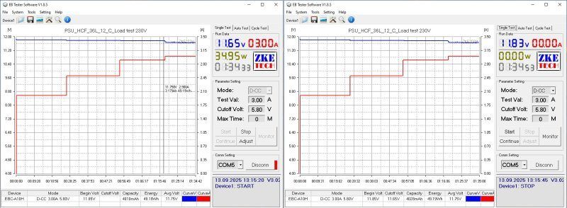
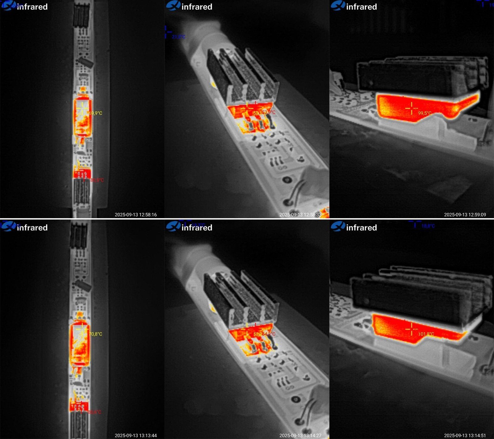
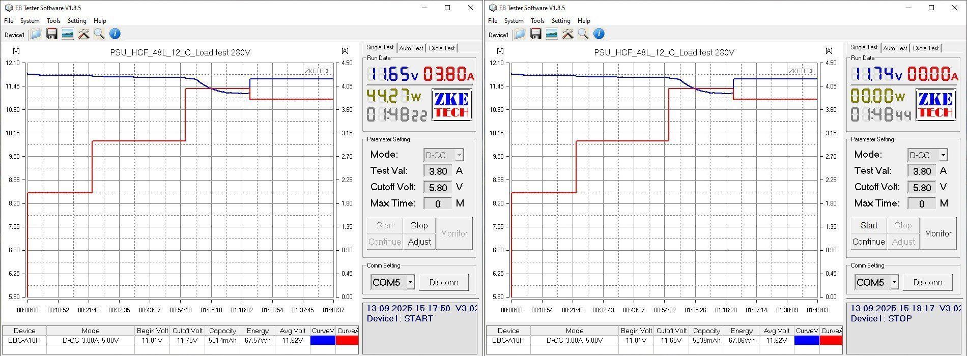
The temperature test was carried out in four stages, at 2, 2.5, 2.9, and 3 A. I split the last test into stages because I was worried the protection might trip, and wanted to test it all in one go.
But everything went fine, and the power supply then ran at 3 A.
The voltage is practically unaffected by temperature. It does vary with load, but that's probably due to the voltage drop in the wires; the power supply itself regulates the voltage well.
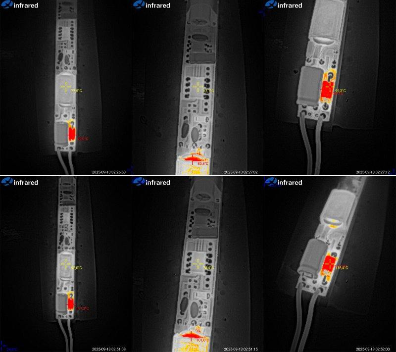
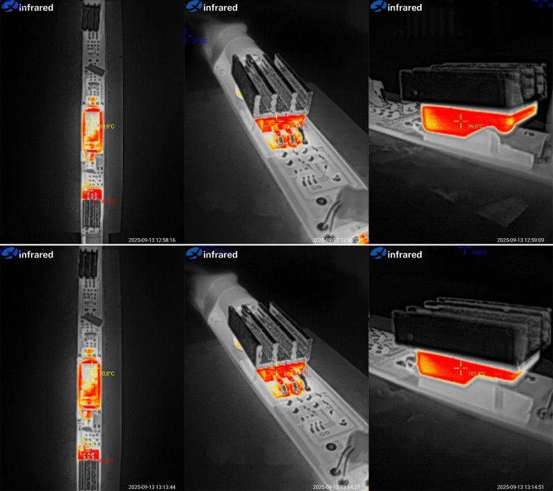
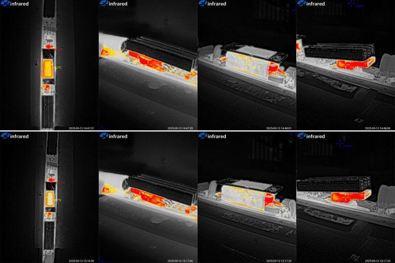
And here are the temperatures, with results at 2.9 and 3 A. I'll comment on the maximum-load results.
Transformer: 71°C, excellent; transistor: 55°C, excellent; output diode assembly: 102°C, a bit high, but tolerable.
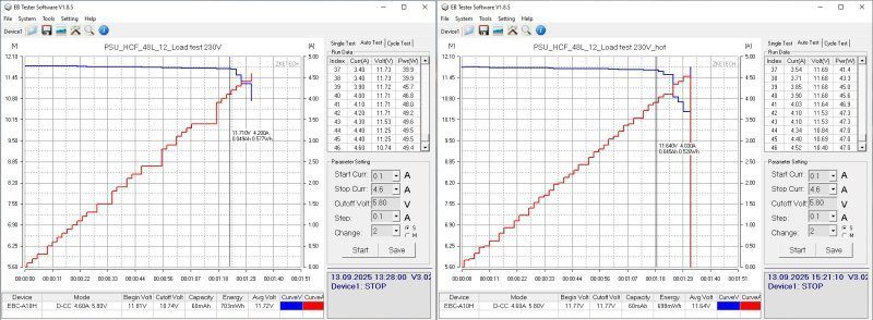
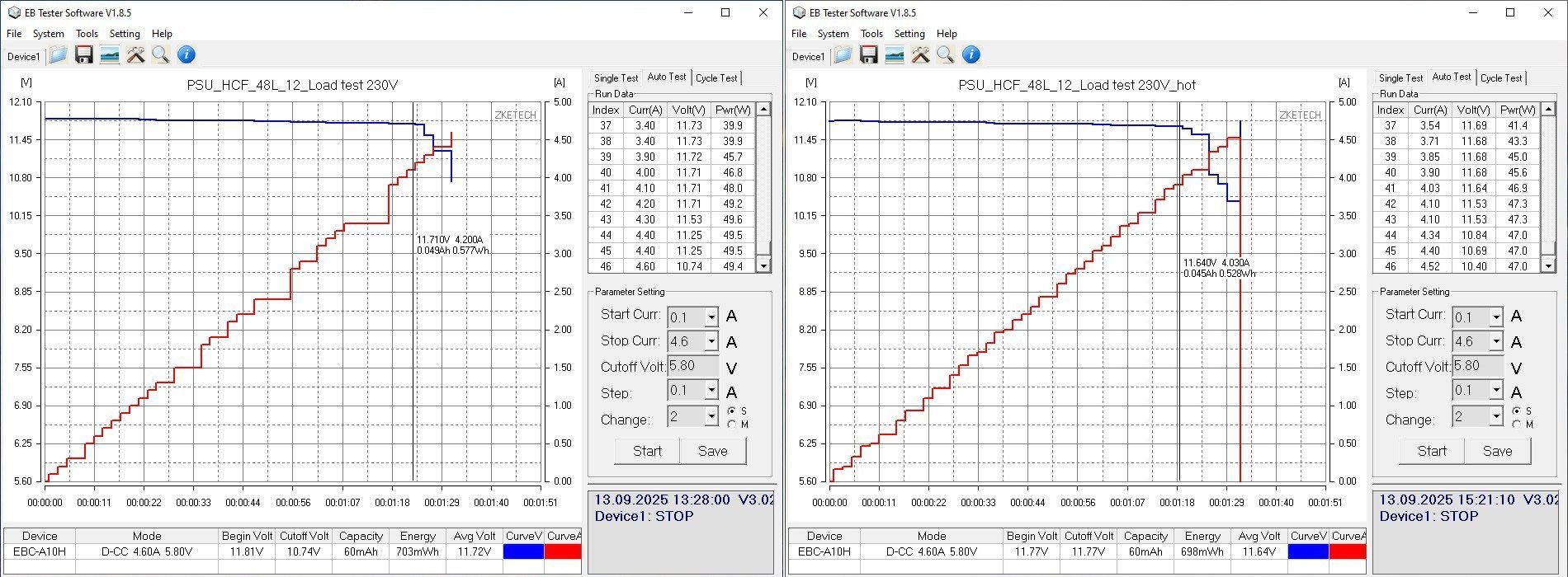
The protection on the second unit is set up better: 4.2 A when cold, around 4–4.1 A when hot. I also had no complaints about voltage stability, with about 40 mV at the power supply terminals across the full range.
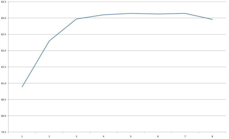
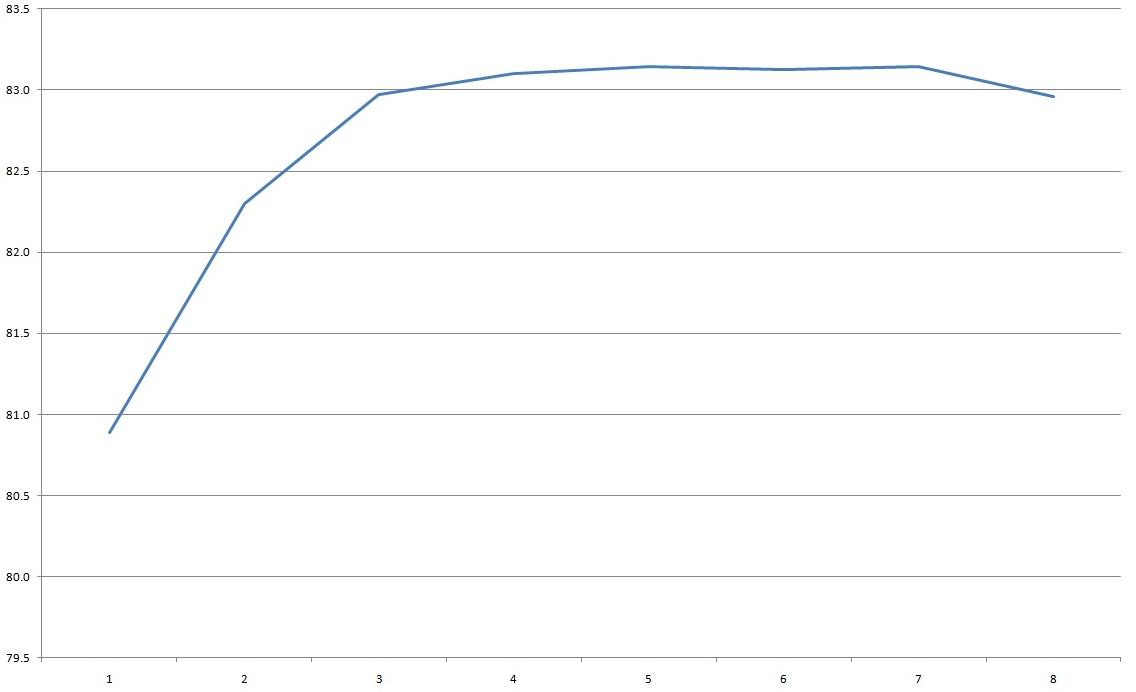
Efficiency is slightly lower, closer to 83%. The horizontal scale is in 0.5 A increments.
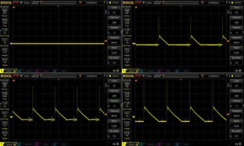
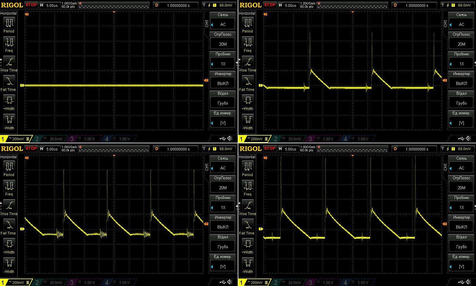
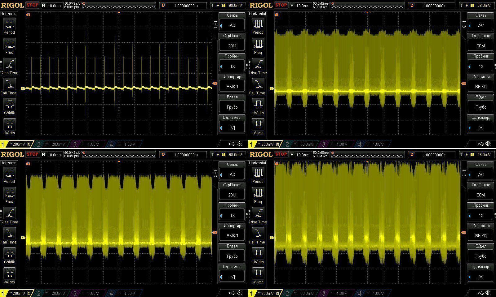
Ripple is a little higher: at maximum current it was around 400 mV here, versus 300 mV on the previous unit. At low frequencies, there are the same 100 Hz spikes and the same radio interference.
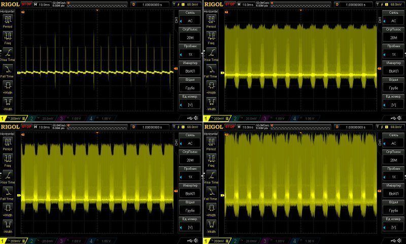
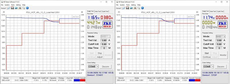
With a sustained load, though, things are a little different. The power supply performed perfectly at 2 and 3 A, but after I raised the current to 4 A, the voltage gradually started to drop. I think that's because the output current depends on temperature, so I effectively hit the power limit.
After that, I reduced the load current to 3.8 A, and the voltage returned to normal.
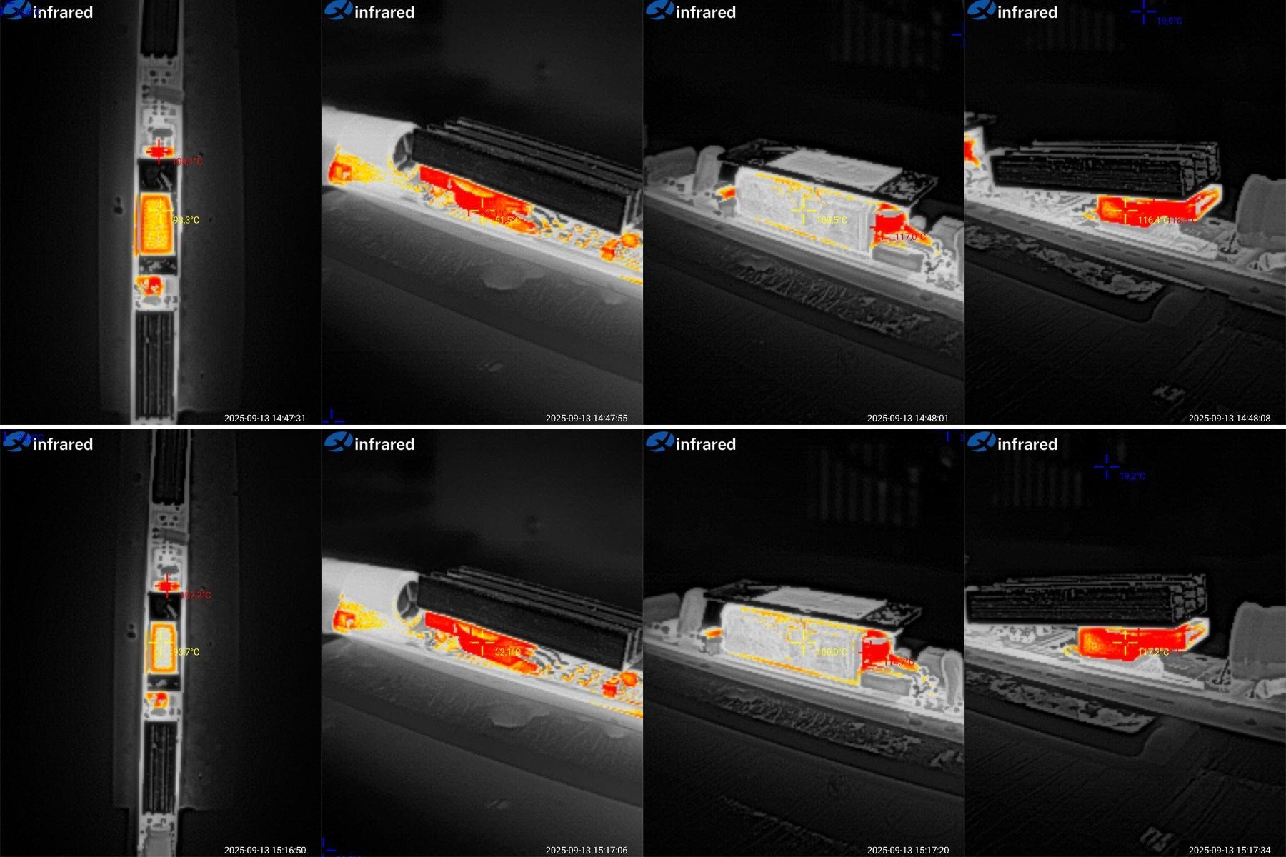
Component temperatures at 4 and 3.8 A.
There isn't much difference, so I'll give the readings at 3.8 A: transformer around 100°C, transistor 52°C, diode assembly 117°C.
In my opinion, 3.8 A is too much for this model. The actual maximum continuous output current is closer to 3.5 A, and taking into account installation in an enclosure and some headroom for ambient temperature, I wouldn't recommend loading it above 3 A.
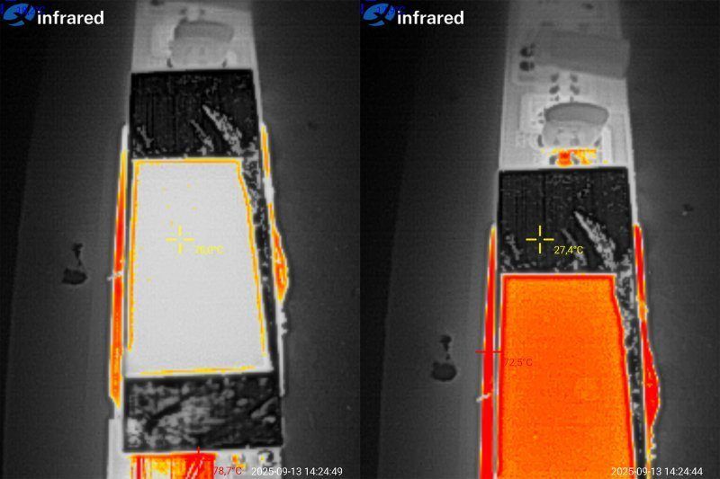
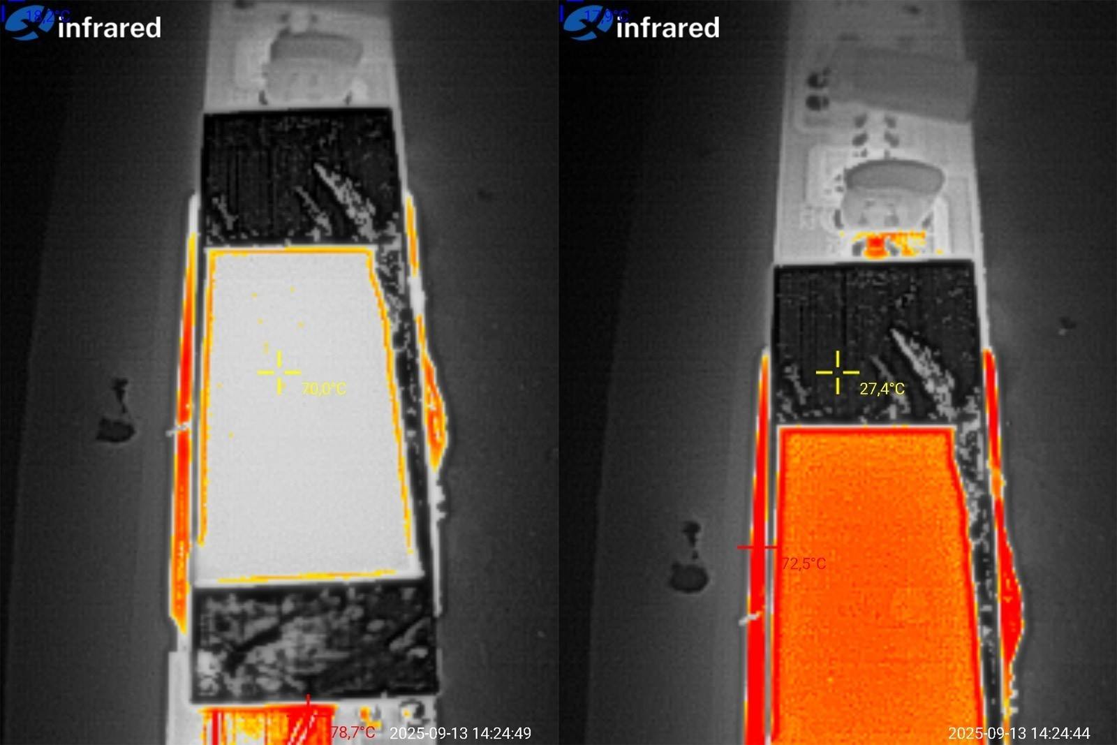
I recently discussed inaccurate temperature measurements with an infrared thermometer, and this is a good example of how readings depend on the surface material.
A piece of black electrical tape (I recommend matte tape) is stuck to the transformer heatsink. It reads 70°C, but if you point the thermometer at the bare metal, it reads 27°C. Quite a difference.
This is because different materials and surfaces have different emissivity and reflectivity. You can usually adjust the emissivity in the instrument settings, but 0.95 is used as a general-purpose default, so it's often easier to “adjust” the surface than the instrument.
So, simply sticking on ordinary electrical tape helps you measure the temperature of surfaces like these more accurately.
In other words, you can accurately measure the temperature of the tape, and by sticking it onto the object you're measuring, you'll get the object's temperature. Yes, there will still be a small measurement error, but it's negligible.
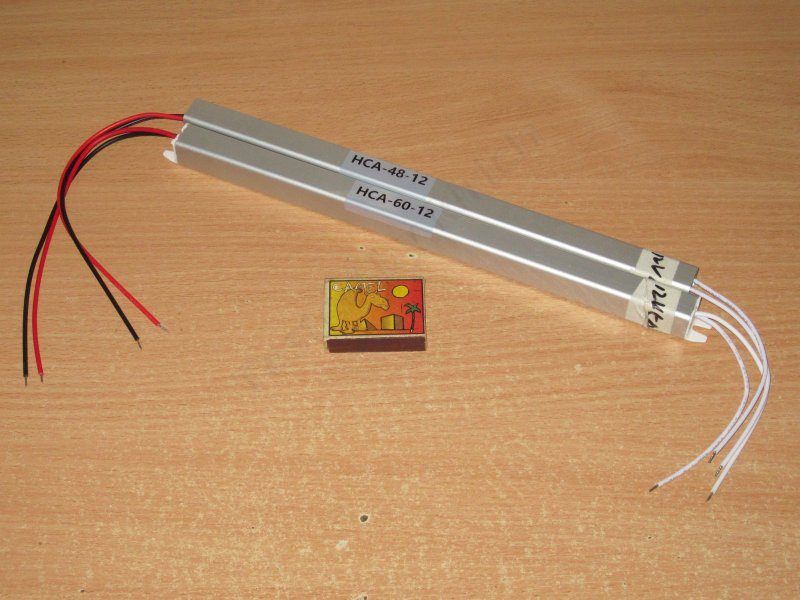
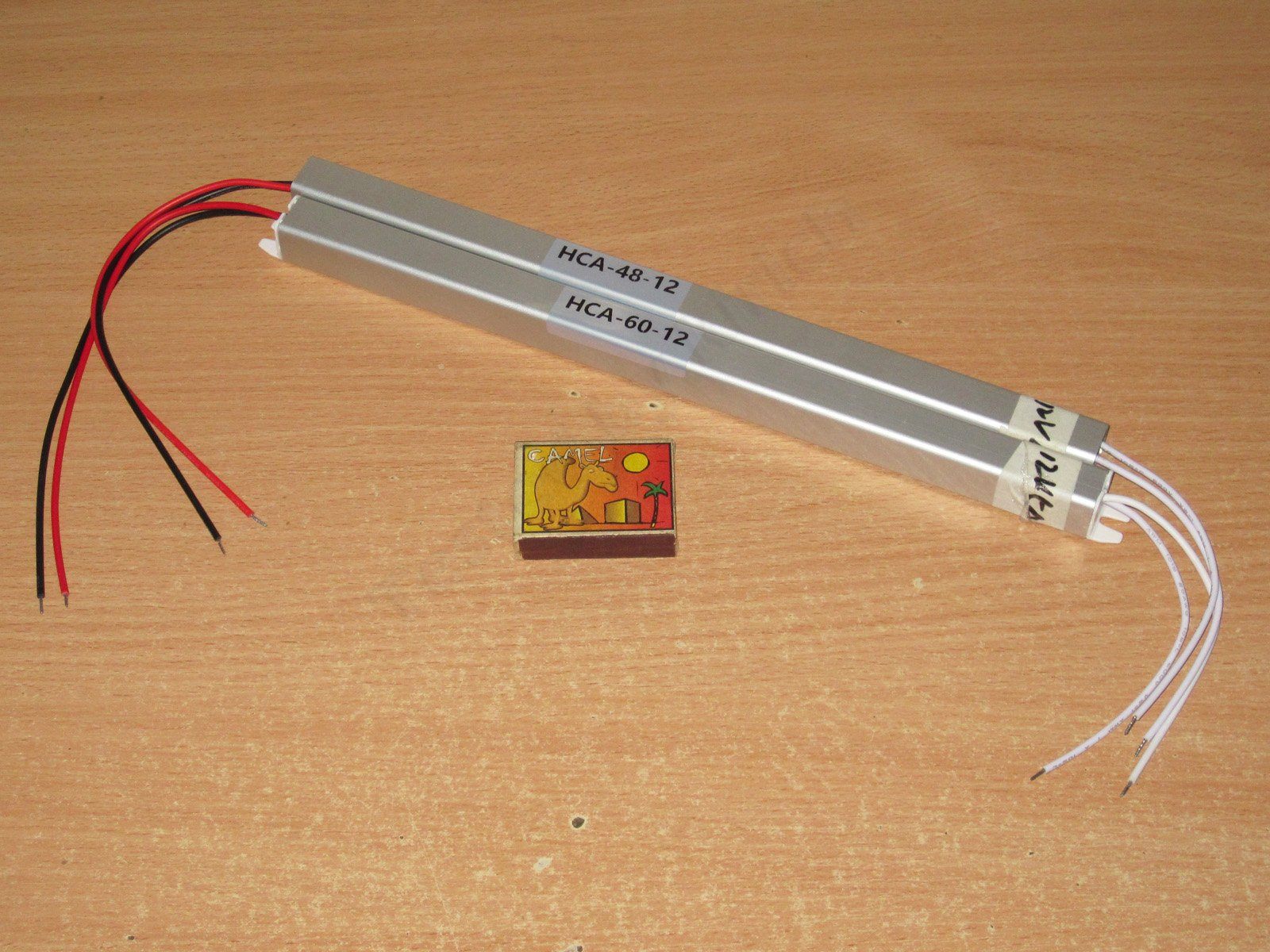
The third pair: HCA-48 and HCA-60, rated at 48 and 60 W respectively, with currents of 4 and 5 A.
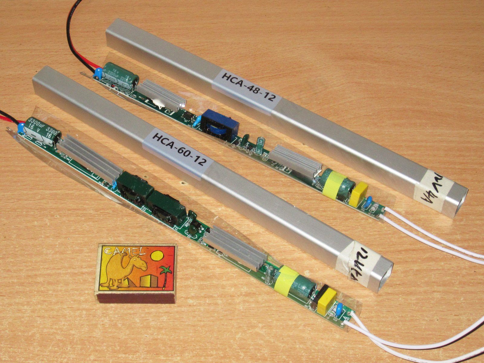
These have a different enclosure design: fully enclosed. But these power supplies aren't potted, even though they look sealed.
The enclosure is 293/313 mm long, with a 17.5 × 17.5 mm cross-section. The wires seem to have plastic insulation, and are quite stiff.
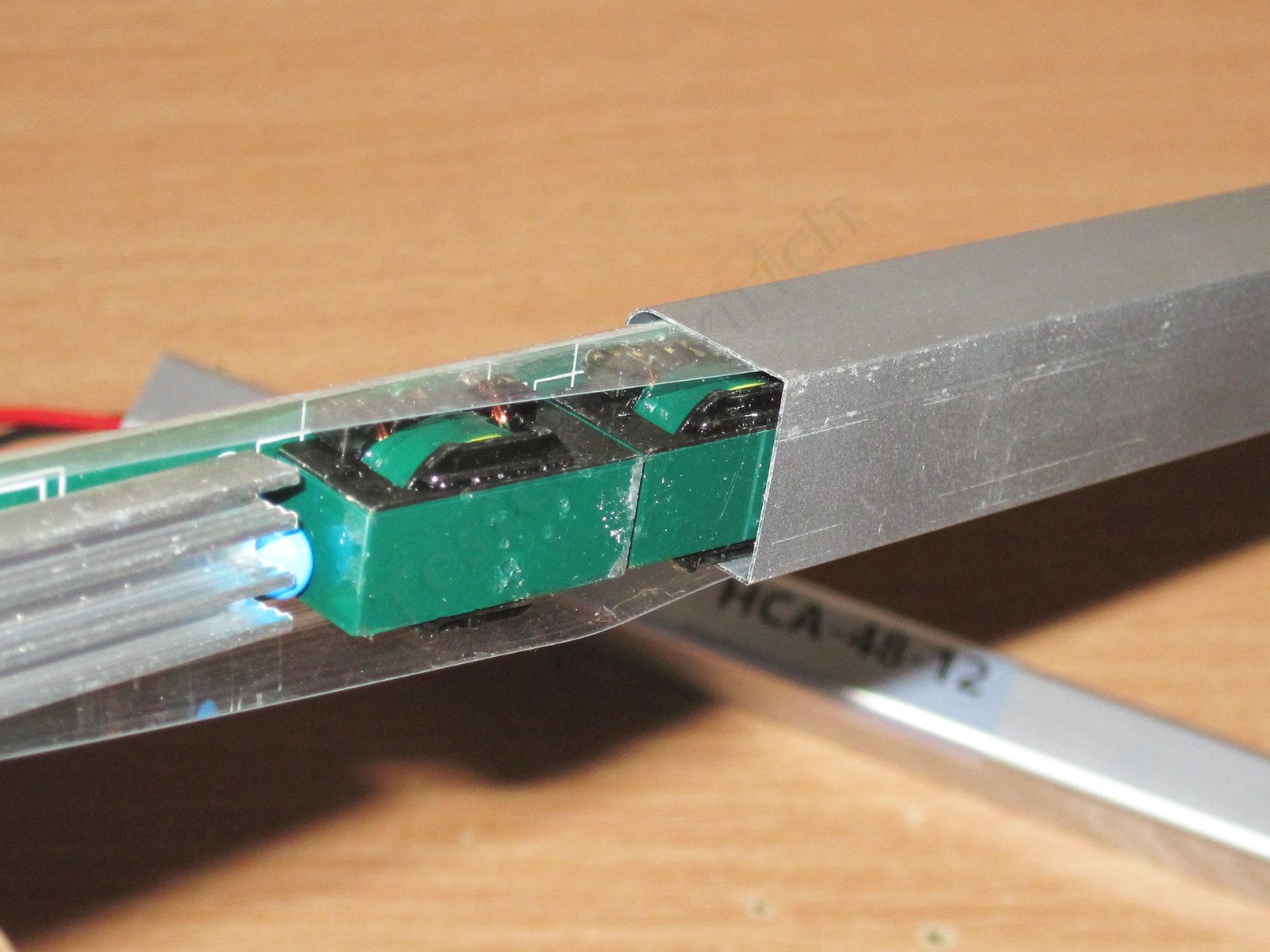
The insulation is a little better here: the board is covered about three-quarters of the way with protective film. In theory, a short could occur in two cases:
1. A transistor heatsink comes loose and connects the enclosure to a trace on the board.
2. A breakdown through the ferrite. Some grades conduct electricity, but this is less likely here because the solder mask on the board and the insulation around the core provide protection.
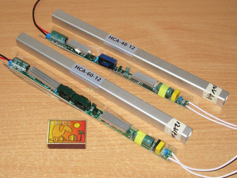
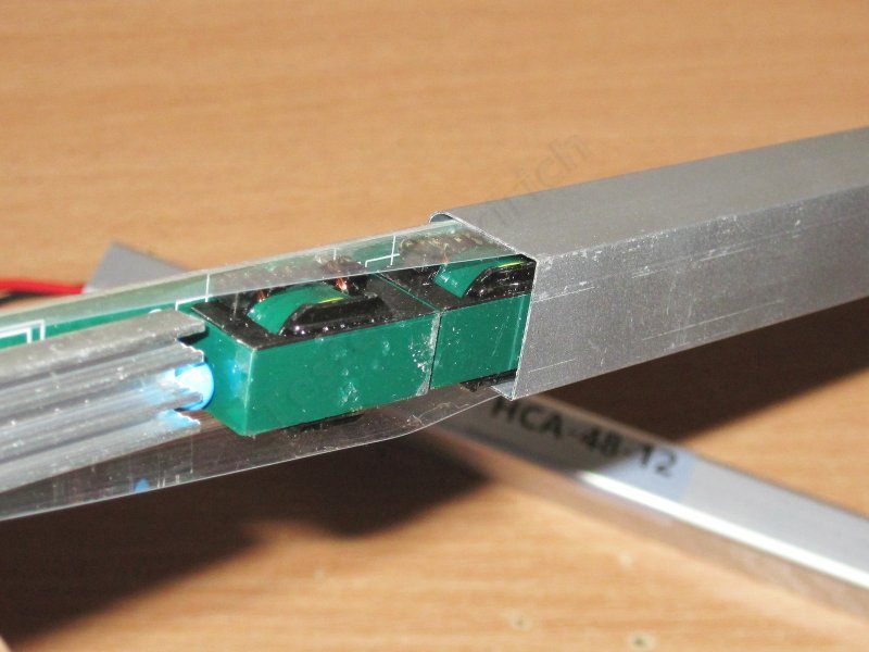
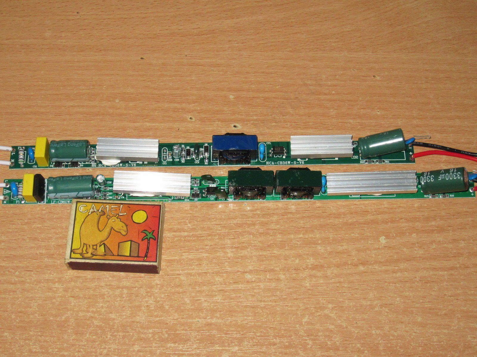
Although the power supplies look exactly the same on the outside, their internals differ quite noticeably—not just in PCB size and components, but also in board layout. In other words, these are essentially two different power supplies that look the same.
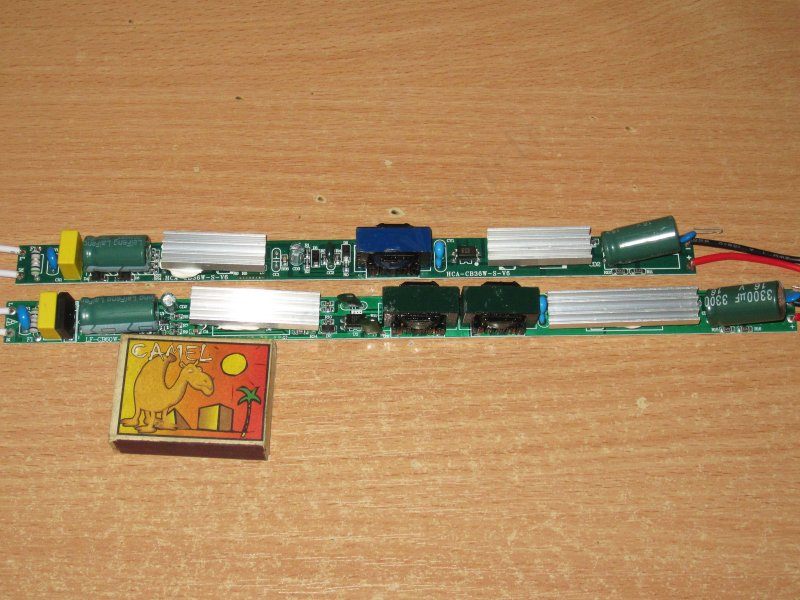
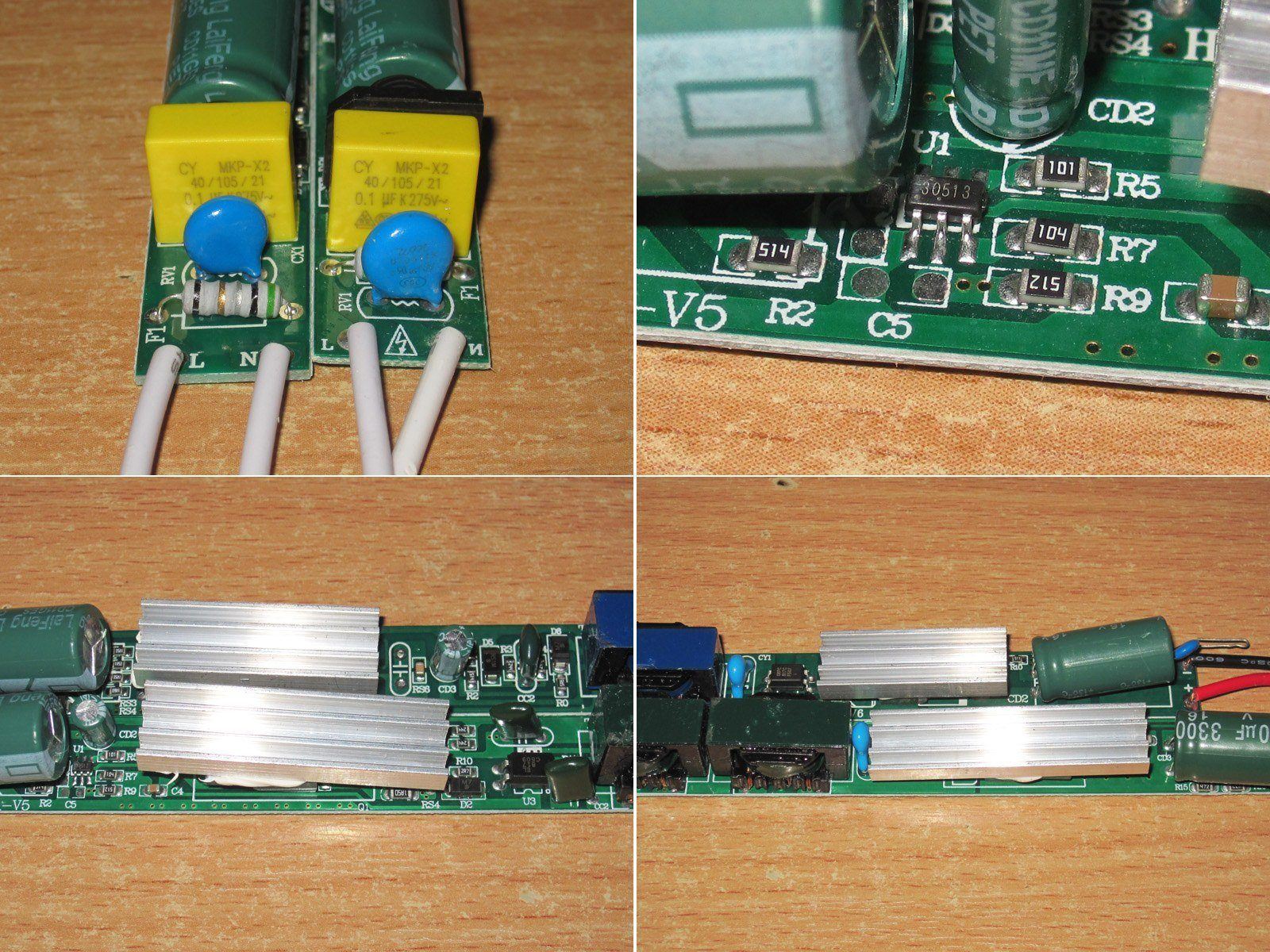
Both boards have a varistor at the input, rated at 560 V peak, I think, an X capacitor, and a resistor that serves as a current limiter and fuse. Overall, this is a bit strange. Even the 18 W versions had a thermistor and a proper fuse, but here they decided to cut costs?
The PWM controller is marked 30513.
The 60 W version has slightly larger heatsinks, but I think they could have made them even bigger. As it is, they transfer heat to the case through the air, which isn't very effective.

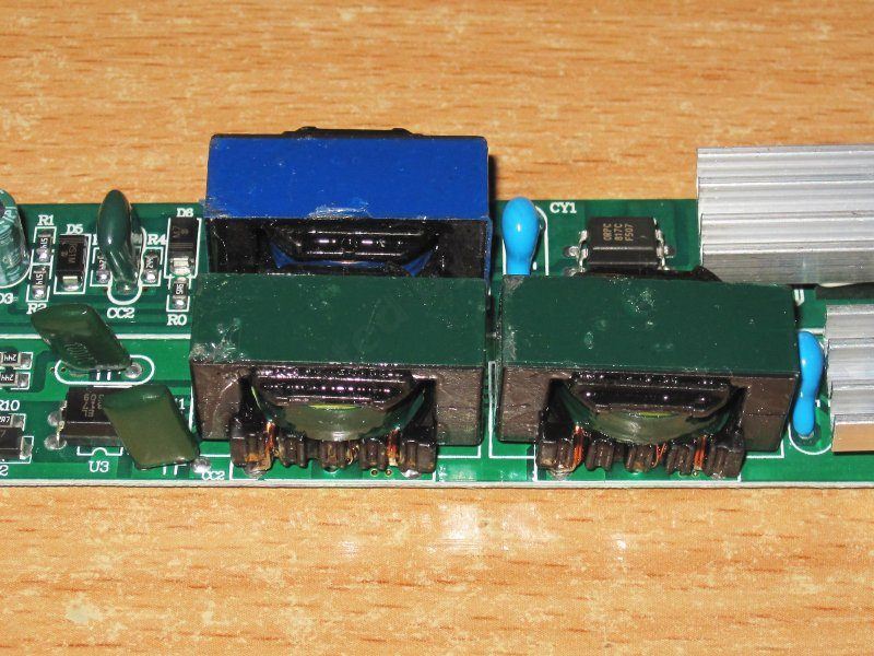
What really takes some getting used to is that the 60 W version has two transformers. Well, that's a perfectly valid approach, but it's fairly uncommon. I've often seen this in low-voltage inverters, but this is the first time I've come across it in a power supply.
The photo shows that the transformers are the same size. So if the 48 W version has a 48 W transformer, the 60 W version must have 96 W worth of transformers. Or, if the 60 W version has two 30 W transformers, then the 48 W version seems a bit underpowered.
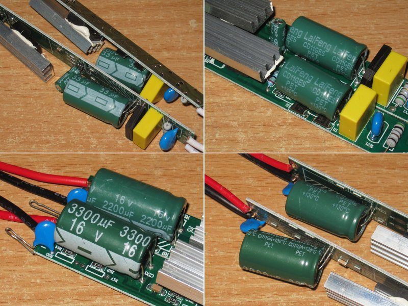
1. Both power supplies have 33 µF input capacitors, again rated for 130 degrees. You can also see here that the capacitors have the same capacitance but different sizes. How do the Chinese manage to make capacitors with the same capacitance in different sizes, yet capacitors with different capacitances that are almost the same size? Naturally, I'm comparing capacitors from the same series.
2. On the output, the 48 W version has a 2200 µF capacitor, while the 60 W version has a 3300 µF one.
I won't complain about the output capacitors, but they could have used a larger input capacitor, at least in the 60 W version. 33 µF is rather small for 60 W, even with a 230 V input.
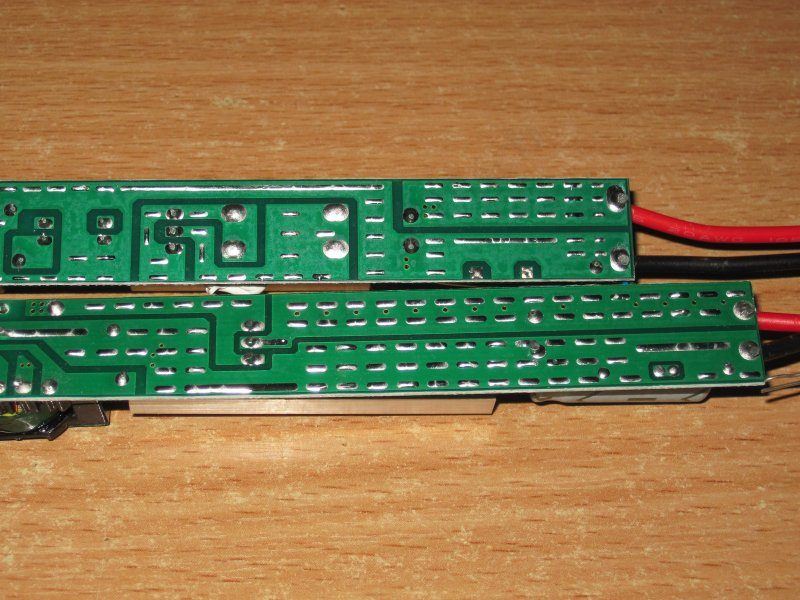
The boards are also noticeably different. About the only thing they have in common is their thickness, which seems to be around 0.7 mm. The 48 W version has a safety weak spot: the copper pour edge is very close to the optocoupler's “hot” side. I think simply moving that copper pour at least 1–2 mm farther away would make it noticeably safer.
The 60 W model is noticeably worse. First, the optocoupler itself is on the hot side, and the high-voltage traces run right up against it. In short, this is bad.
I also noticed a strange trace on the 48 W version; I can't see what it's for.

The output is as usual: they went all out with the copper pours on the power rails, filling the entire width :)
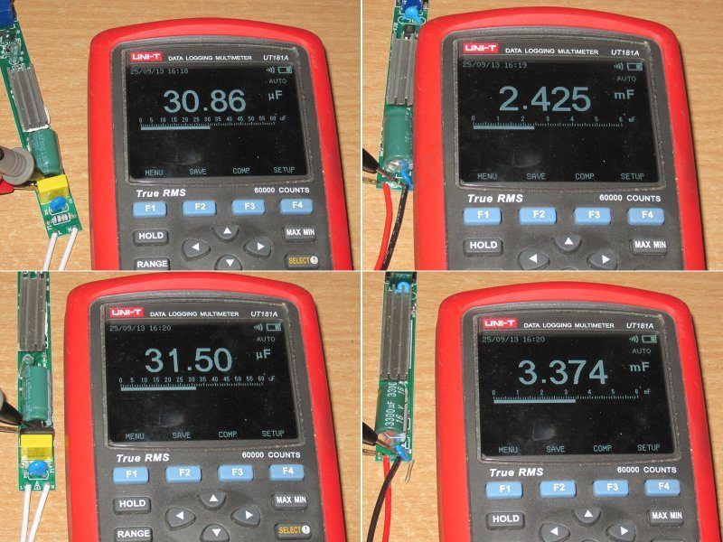
The measured capacitance is roughly in line with the values printed on the capacitors: 48 W on top, 60 W on the bottom.
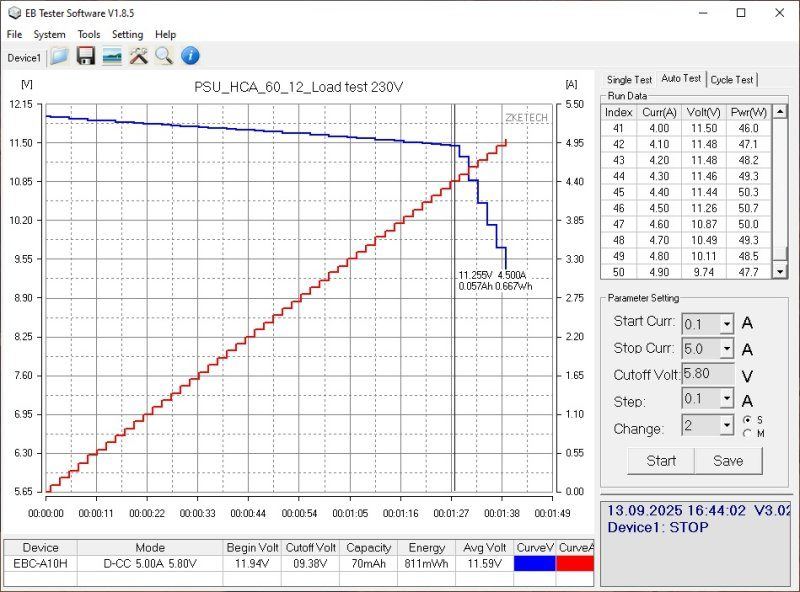
The 48 W power supply's protection kicks in at around 4.5 A. When hot, the current is 0.1 A lower, which is normal.
But what surprised me right away was how much the voltage depends on the load.

My first thought was that the wires must be really thin, but connecting the load directly to the power supply output didn't improve things much. At full load, the output voltage drops by about 0.8 V, which is a lot.
The screenshot has the wrong model name; it should say 48 W, not 60.
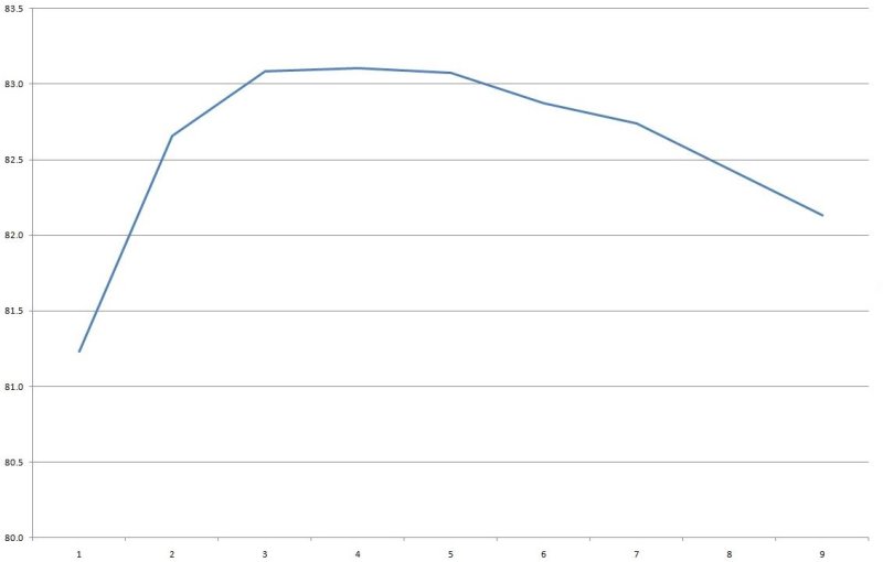
Efficiency is around 83%, but the graph has a bit of a hump to it. The horizontal axis is in 0.5 A increments.
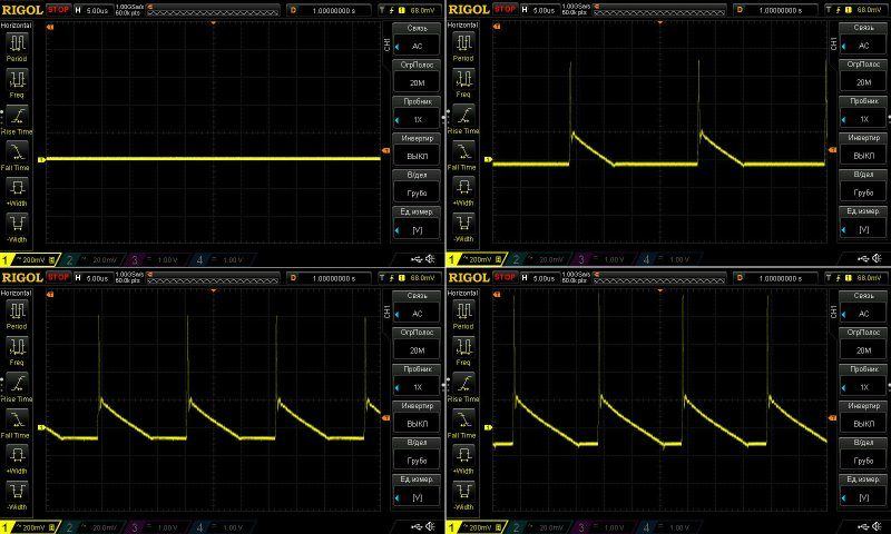
High-frequency ripple with no load and at currents of 1.3, 2.6, and 4 A.
Nothing unusual here: there are spikes, and the main ripple has an amplitude of about 190 mV. Neither good nor bad, just acceptable. Ripple below 1–2% is generally considered normal, which for a 12 V power supply works out to 120–240 mV. But a lot depends on the intended use and the nature of the load.
At low frequencies, everything looks fine. There's no significant 100 Hz component, just general noise, most of which will be “soaked up” by the wires to the load.

The load test was essentially run at three current levels: 2, 3, and 3.5 A. I initially set the current to 4 A, but then reduced it to 3.5 A because things were already getting pretty hot at 3 A.
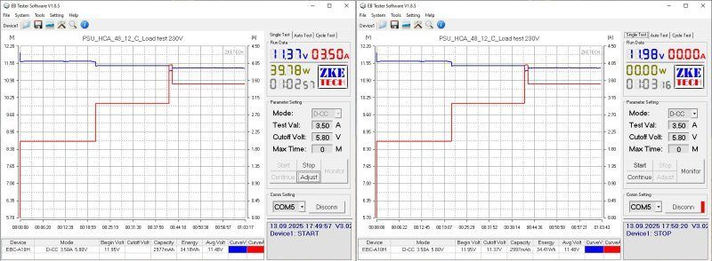
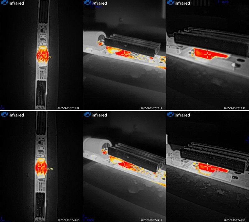
And here are the results.
At 3 A: transformer 95, acceptable; transistor 46, excellent; diode assembly 97, acceptable.
At 3.5 A, things are worse: transformer 114, high; transistor 50, excellent; diode assembly 108.5, tolerable, but at the limit.
Overall, it's clear that even 3 A is a struggle for this power supply. I think that's its long-term maximum in the case at room temperature, mainly because of the transformer temperature.
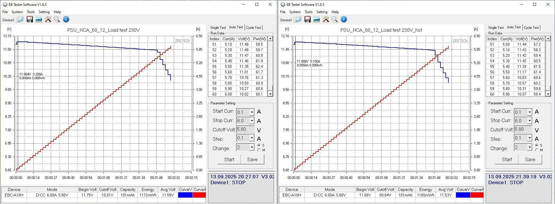
The 60 W version did better in terms of voltage stability, with a maximum deviation of 80 mV.
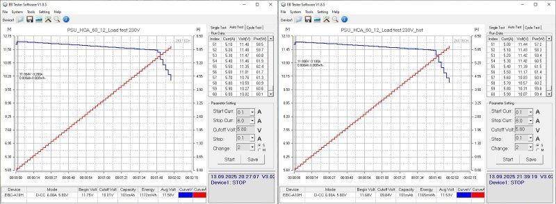
But one thing did crop up, more commonly seen in smartphone chargers: the voltage rises under load. The graph shows a sharp increase of about 0.11 V right at the start, followed by a gradual drop as the load increases.
The protection kicks in at a current of about 5.4 A, regardless of temperature.
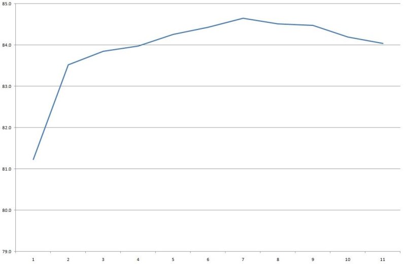
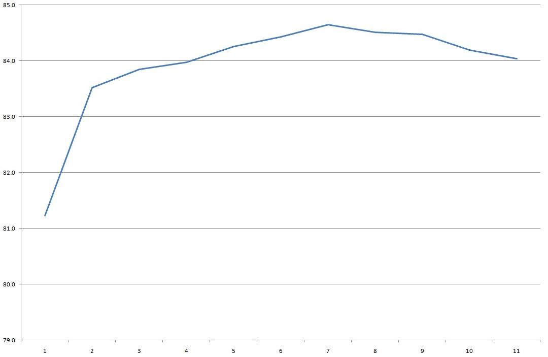
Interestingly, efficiency is slightly higher here, at around 84–84.5%. I think that's because the two transformers have a lower equivalent winding resistance than the single transformer in the previous model.
The horizontal scale is in 0.5 A increments.
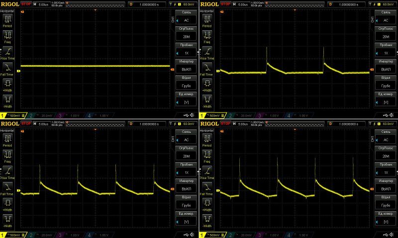
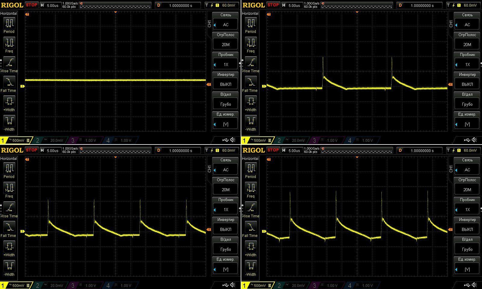
Ripple is a real problem here, though. Below are the results with no load and at currents of 1.5, 3, and 5 A.
At maximum current, the main ripple is around 650–700 mV, or about 5%—that's a lot. It's probably acceptable for LED lights and the like, where the requirements are much less stringent, but personally, I'm not a fan.
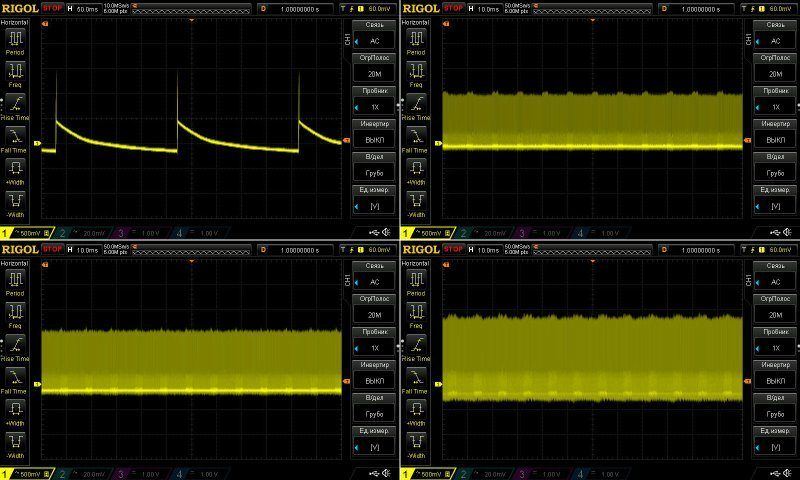
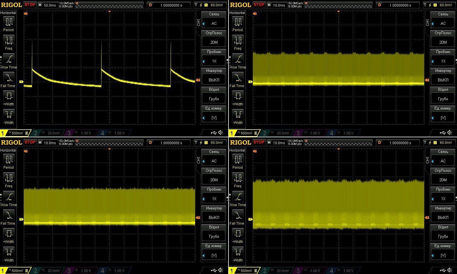
At 100 Hz, things are surprisingly fine, apart from the overall ripple, of course. I did notice right away, though, that "green mode" runs at a noticeably lower frequency. It even felt like this wasn't green mode at all, but the power supply had switched to burst mode, since the pulses come at 0.25-second intervals. Perhaps it uses a different PWM controller, or perhaps this is some characteristic of this circuit design and topology.
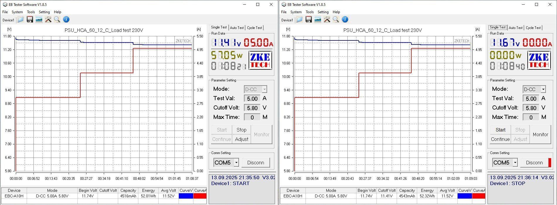
The load test was run at 3, 4, and 5 A. Voltage does vary with temperature, but only slightly; the load current has a more noticeable effect.
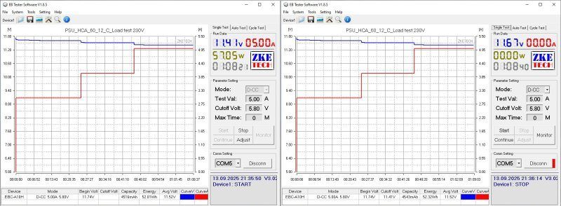
And here are the temperatures at load currents of 4 and 5 A. Just to clarify, by the first transformer I mean the one closer to the power supply input.
At 4 A: first transformer, 64°C; second, 66°C—excellent. Transistor, 60°C—excellent. Rectifier assembly, 96°C—acceptable.
At 5 A: first transformer, 74°C; second, 80°C—excellent. Transistor, 73°C—excellent. Rectifier assembly, 115°C—at the limit; it will overheat inside the enclosure.
So the actual continuous current for this power supply is around 4 A. The low transformer temperatures are reassuring, since they're the most delicate components.
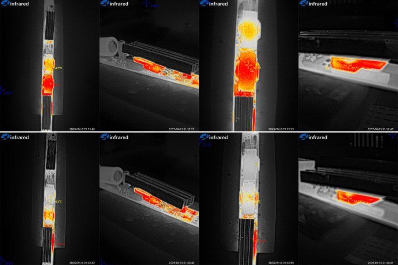
The fourth pair consists of the models that were different in the first place; I've grouped them together simply for consistency.
Models HCF-60L and HCA-72, rated at 60 and 72 W, with output currents of 5 and 6 A, respectively.
Dimensions:
HCF-60L — length 296/316 mm, cross-section 17 × 14 mm, silicone-insulated wires.
HCA-72 — length 357/377 mm (I had to get out the tape measure), cross-section 17.5 × 17 mm, wires with "plastic" insulation.
As you can see, the 60 W model is an extended version of the 18, 24, 36, and 48 W models shown earlier. The 72 W version is similarly an extended version of the 48 and 60 W models from part three.
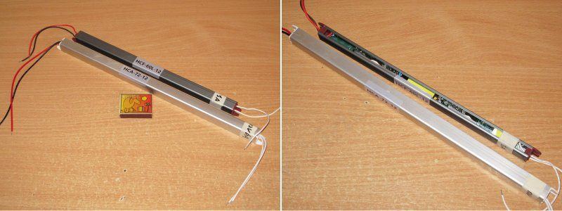
Interestingly, the 60 W model has only one transformer, and its enclosure has a smaller cross-section than the previous models. The 72 W model, on the other hand, has two transformers.
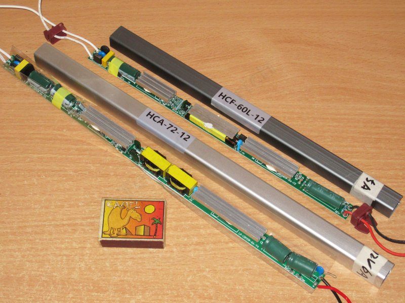
Since these models have little in common, this part of the review is split into two sections, one for each power supply. Naturally, I'll start with the 60 W version.
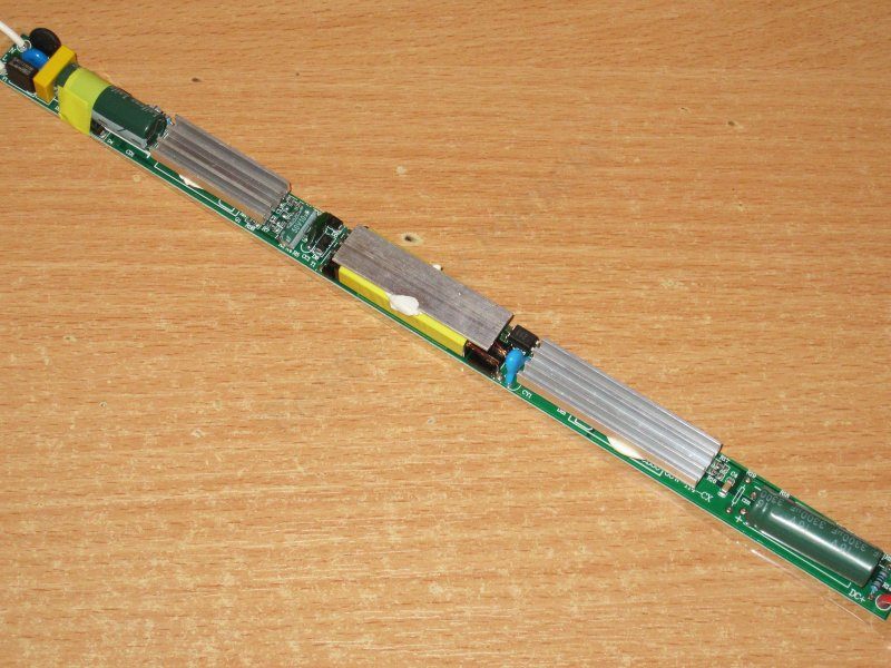
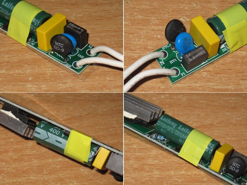
The input section is the same as in the previous HCF models: a thermistor, a varistor, and a proper fuse.
There's one capacitor, rated at 33 µF, and its temperature rating is also up to 130°C.
1. PWM controller 30509, the same as in the 36 and 48 W versions. I expect the interference issues to be the same, too.
2. There's only one transformer, but it's quite long, and they've attached a heatsink to it. I'm not sure how effective that is; to me, it just increases thermal inertia, and that's about it.
3. They've glued a really long heatsink to the output rectifier assembly. But judging by the gaps and the thickness of the adhesive layer I've seen on other models, it's unlikely to be as effective as it could be if it were attached properly—or, better yet, screwed down with thermal paste.
4. The output capacitor is 3300 µF, rated for 130°C.
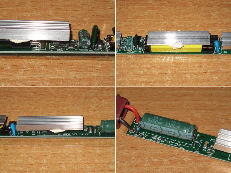
The board layout is similar to the 36 and 48 W HCF models, with the same shortcomings; the board itself is simply longer. The insulation is also only on the underside of the board. Given that the traces run right along the edge, this is quite dangerous—use only in enclosed housings.

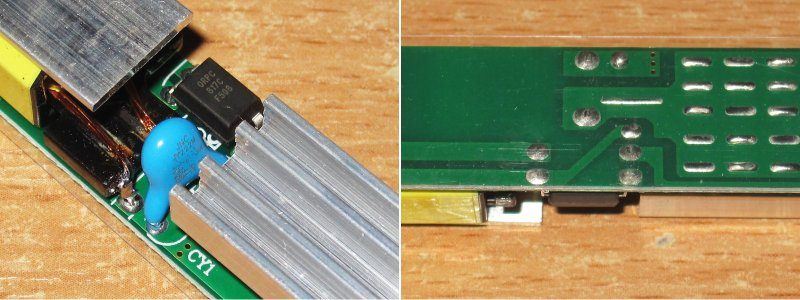
Here's a closer photo of the problem area. I think the issue is clear: the "hot" lead of the Y capacitor is too close to the output-side copper pour. With a slight change to the PCB layout, it can be made noticeably safer, though still not perfect.
As before, I should point out that the input capacitor is a bit small for 60 W, especially with a lower input voltage.
No complaints about the output capacitor. It could be larger, but this is probably fine.
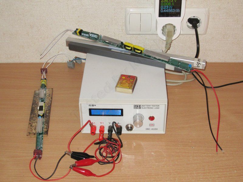
One more photo from the testing process. Here I wanted to show how little power these power supplies draw with no load: around 0.15-0.3 W. I remember when we used to be proud if a power supply drew about 1 W; now Chinese models draw three to five times less.
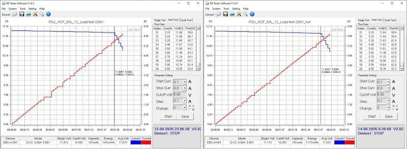
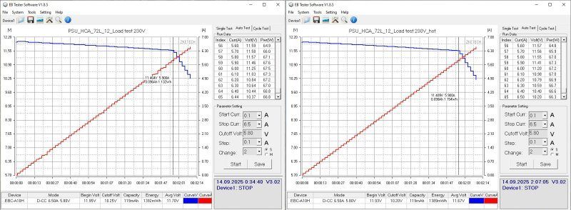
The protection trips at around 5.6 A and is almost unaffected by heating. Voltage regulation is quite good.
You can also see here that even with USB galvanic isolation, communication still gets stuck.
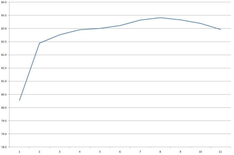
Typical efficiency, around 83-83.5%. The horizontal scale is in 0.5 A increments.
Ripple, as usual, with no load and at approximately 33%, 66%, and 100% load.
At high frequencies, everything is typical: around 400 mV at maximum current. Not great, but acceptable for undemanding loads.
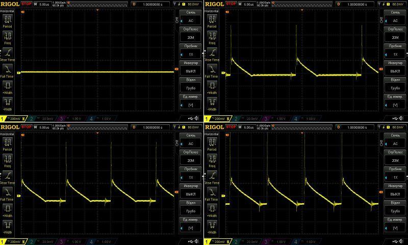
I wasn't too happy with the low-frequency results. I wouldn't call them critical, just ugly: the 100 Hz component is quite noticeable.
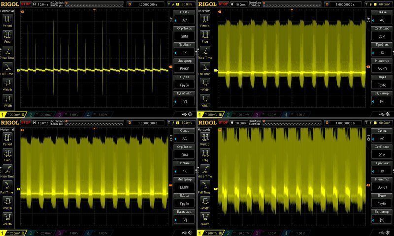
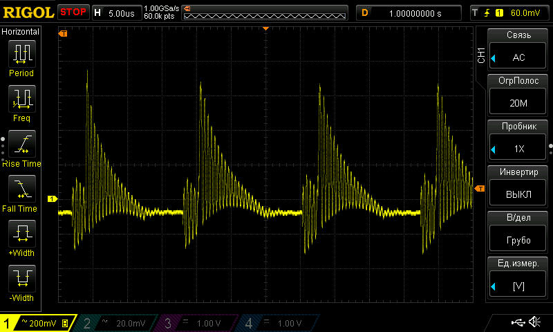
And, just like the 36 W and 48 W versions, there's a resonance that is most likely causing interference over the air.
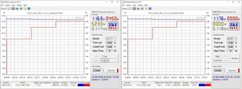
The load test was carried out in three stages, at 3, 4, and 4.5 A. I didn't try the claimed 5 A, because the power supply was already struggling at 4.5 A.
Voltage varies only slightly with temperature, by around 50 mV, and by about 80 mV across the full load-current range. That's fine.
Now for the temperatures.
At 4.5 A, I measured around 100°C on the transformer, 62°C on the transistor, and 105°C on the diode assembly.
In principle, the current could be raised to 5 A, but in my opinion that's too much for this unit. The actual continuous output current in the case should be no more than 4 A.
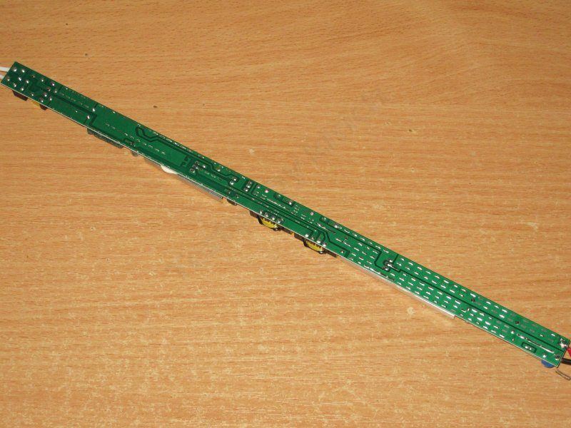
Now for the HCA-72 model.
It was quite a challenge to fit this thing into the frame—it’s that long. As with the other models in this case, insulation is provided by a plastic barrier covering about 3/4
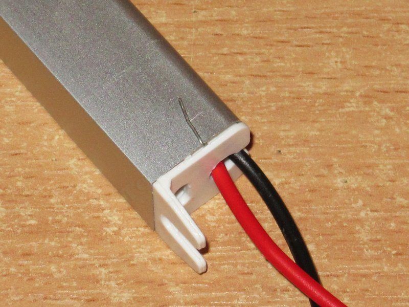
These models have a very unusual way of grounding the case: a bent capacitor lead sticks out. In my opinion, it's a poor design. First, it can easily break off; second, it's even easier to catch yourself on it and get hurt.
Surprisingly, the input section here is very similar to the HCF series models: it has a fuse, thermistor, and varistor.
The bridge rectifier is larger, there are two 22 µF, 130°C capacitors, and the transistor has a relatively large heatsink. But the PWM controller is a 30513, as in the other HCA series models, not the HCF models that spewed interference.
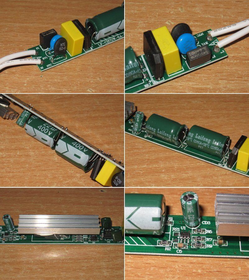
Two conventional transformers; no complaints here. This worked fine last time.
But they left the optocoupler on the hot side. Not good :(
On the output side, there are two 2200 µF, 130°C capacitors. That's fine here.
There's no point commenting here; I've already described everything about this board. Safety is very poor.
A closer look at the optocoupler section—a good example of how not to do it.
Surprisingly, the input capacitors' capacitance matches the stated value exactly, while the output capacitors are even slightly above spec. That's fine here.
But even 44 µF is a bit small for 72 W.
The protection trips at around 6 A, just barely above the claimed maximum. In a way, that's good for safety.
The current is practically unaffected by the power supply's temperature.
Voltage regulation is reasonably good. The actual variation at the terminals was around 70 mV. As the current rises to 6 A, the voltage immediately starts dropping by 0.3 V.
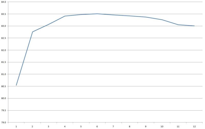
Efficiency is 83-83.5%—nothing new, all quite typical. The horizontal scale is in 0.5 A increments
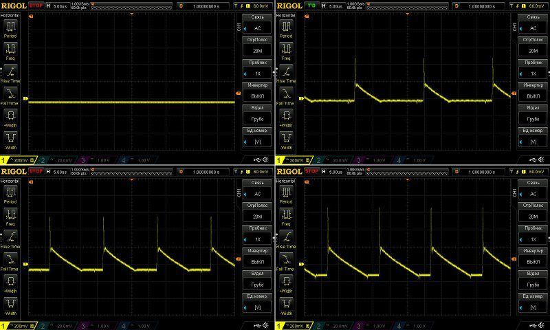
Ripple with no load and at currents of 2, 4, and 6 A.
Basically, it's acceptable: even at maximum load it's around 370–380 mV, about 3%. At 4 A it's perfectly fine, around 240 mV, which is to be expected for this class of power supply.
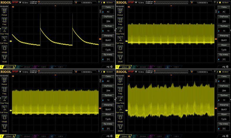
At low frequency, you can see the characteristic ripple with no load. I'm now inclined to think this is a characteristic of the PWM controller used, since we've seen this before.
There's almost no 100 Hz ripple, and the last screenshot is more likely showing the overload protection starting to kick in.
The temperature test was run at currents of 3, 4, 5, and 5.5 A. As I mentioned, the voltage doesn't vary much with temperature. It does vary with load, but that's mostly due to voltage drop in the wires.
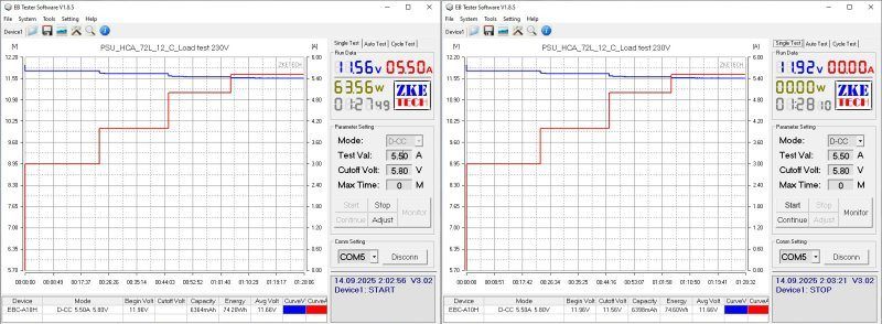
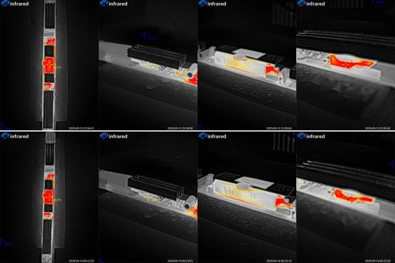
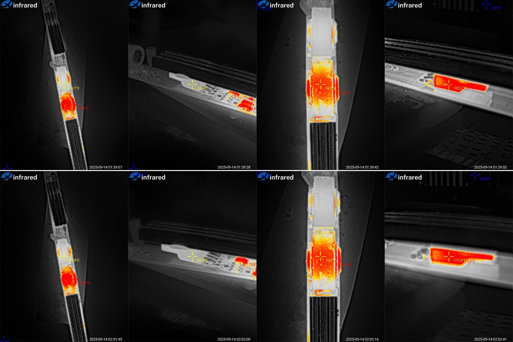
And of course, the temperatures. These photos were taken at load currents of 5 and 5.5 A.
At 5 A: the first transformer is at 76°C, excellent; the second is at 86°C, higher but still fine; the transistor is at 53°C, excellent; the diode assembly is at 102°C, a bit high.
At 5.5 A: the first transformer is at 83°C, excellent; the second is at 94°C, a bit high but quite acceptable; the transistor is at 56°C, excellent; the diode assembly is at 111°C, too high.
This isn't the first time I've noticed that the diode assembly is usually the first thing to overheat, followed by the transformer, while the high-voltage transistor usually has plenty of headroom. I don't know why they didn't put two diode assemblies in parallel and use a larger heatsink, but it would have worked a little better.
So, in this enclosure, the continuous current should be no more than 5 A.
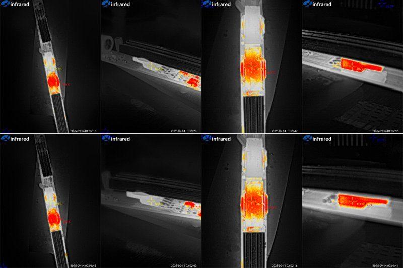
And now the fifth pair: HCA-100 and HCA-100L power supplies. Both are rated at 100 W, with a current of 8.3 A.
Essentially, these are the same power supply. The difference is in the construction: the second one is marketed as sealed, although it isn't potted. The edges around the end caps are simply coated, and the caps themselves are metal. So the sealing here isn't great; it's more that water is less likely to get inside right away.
Dimensions:
HCA-100 - 244/265 mm, cross-section 25.5 × 16.5 mm
HCA-100L - 242/264 mm, cross-section 32 × 17 mm
The cables are like our PVS wire, reasonably flexible.
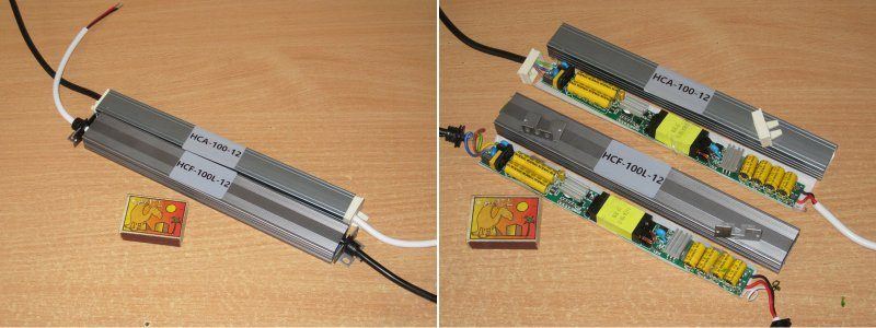
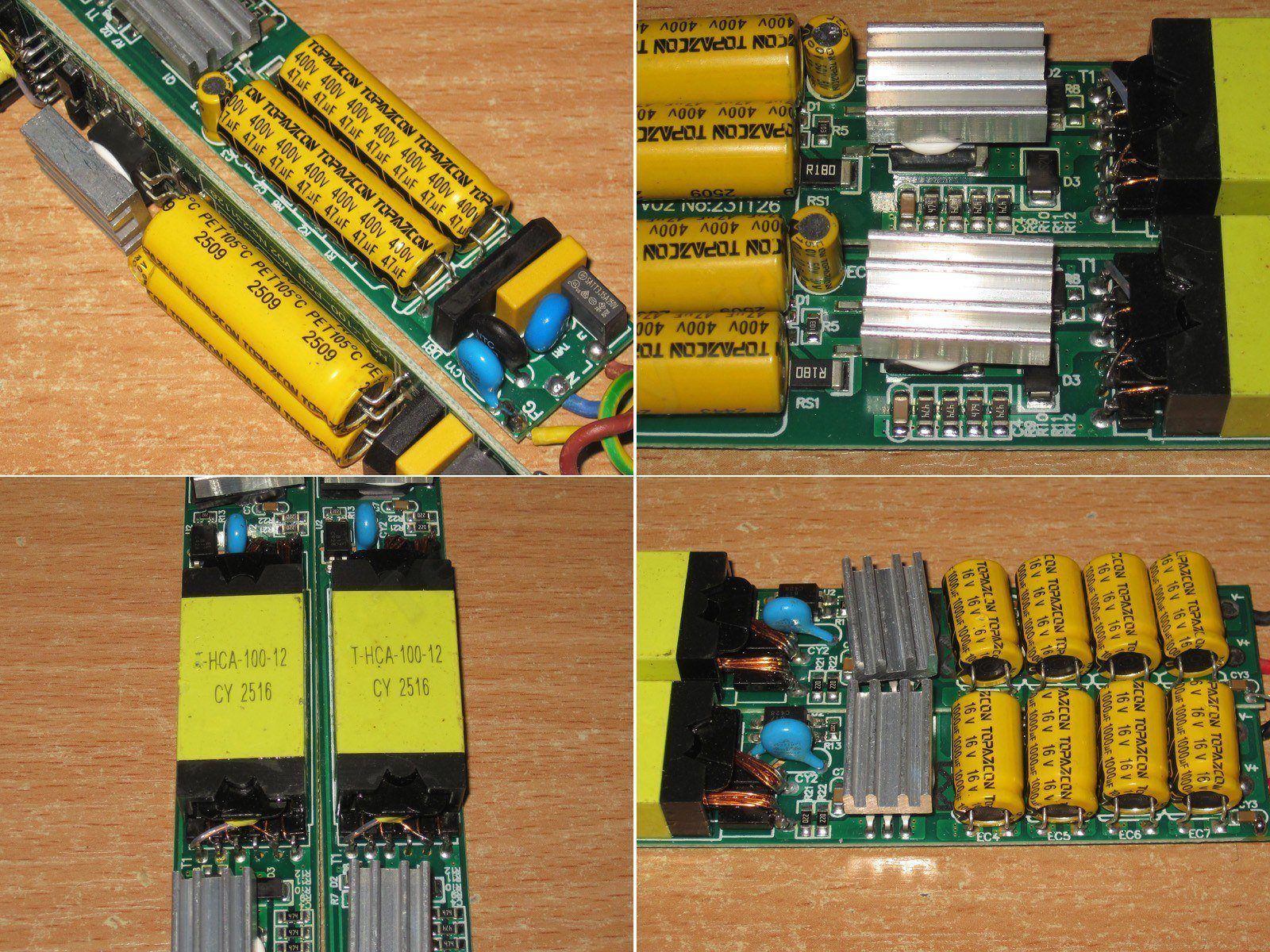
These models have insulation made of a denser plastic, reminiscent of the shades on cheap light fixtures, but it covers less than half the perimeter, forming more of an improvised trough.
And yes, you can clearly see here that these are two absolutely identical circuit boards.
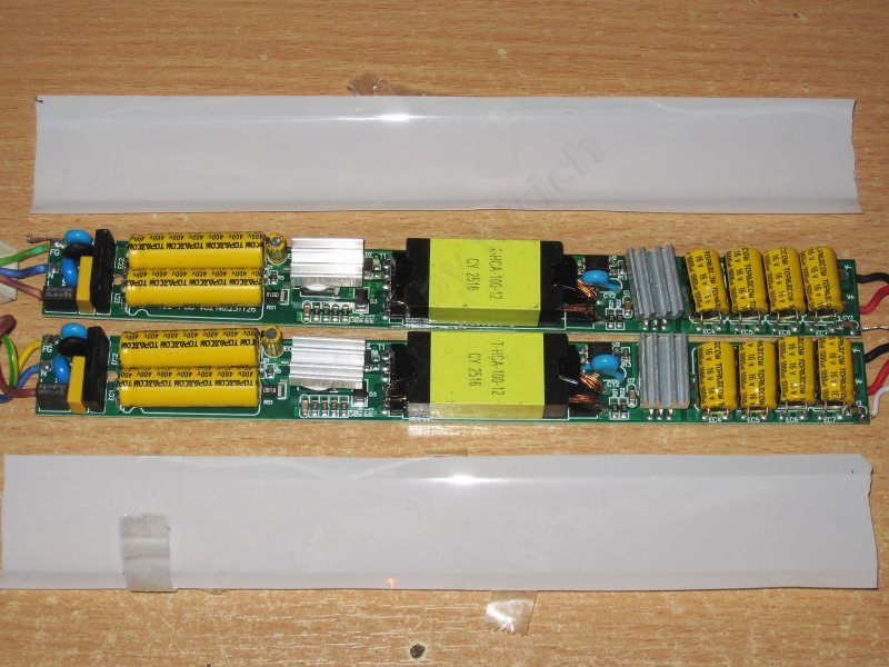
There's no EMI filter inductor, but otherwise everything looks fine: thermistor, varistor, fuse, and X capacitor.
The varistor is rated for a 560 V peak voltage, so it protects against surges in the mains, which most often occur during thunderstorms.
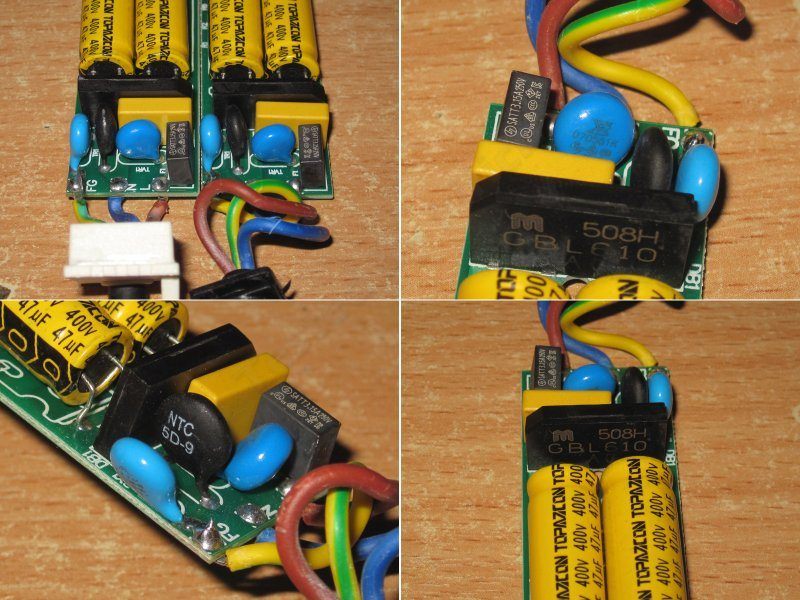
The input capacitors are 47 µF each, almost 100 µF total, which is quite enough for this power rating and our mains supply. But interestingly, all the previous units had 130°C capacitors, while this one uses a different manufacturer and 105°C capacitors.
Even the shunts are identical, rated at 180 mΩ, as are the transformers.
There are four 1000 µF capacitors in parallel on the output. Although the total capacitance is only 4000 µF, I'm glad they used four rather than one large capacitor; this usually has a positive effect on ripple and service life.
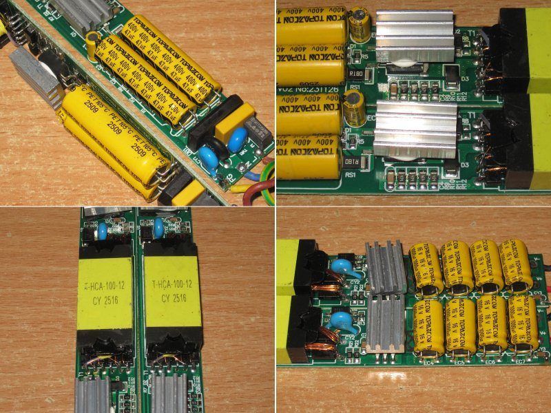
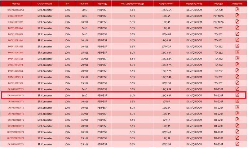
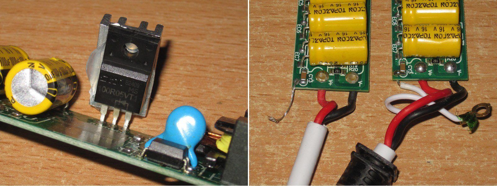
The very small output heatsink immediately caught my attention, and naturally I suspected a synchronous rectifier. And yes, that's exactly what it is. I actually have some just like these at home; I bought them before the war for experiments. I should at least try to find them.
The output is also connected to the case through a capacitor, so the case can act as a shield against outgoing interference. Here, though, the connection is made with a stranded wire.
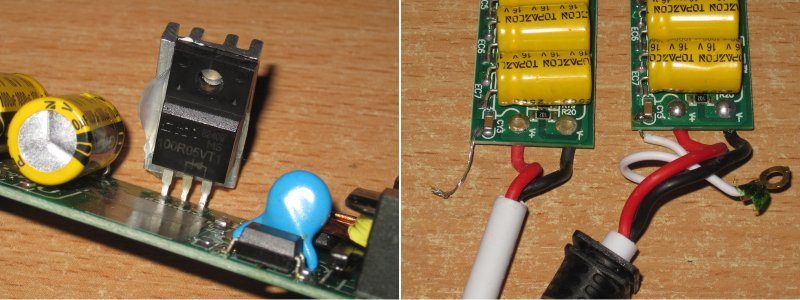
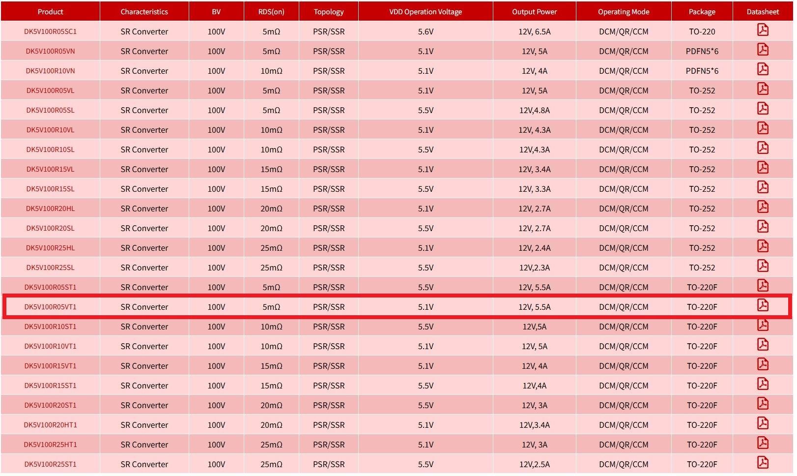
The only thing is, according to the datasheet, although these can handle high current, they're intended for 12 V switching power supplies with currents up to 5.5 A. The highest-current version of this kind of "diode" is rated for power supplies up to 6.5 A, so it's overloaded here.
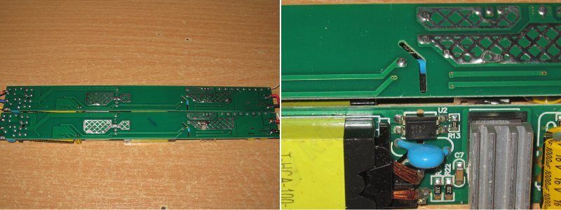
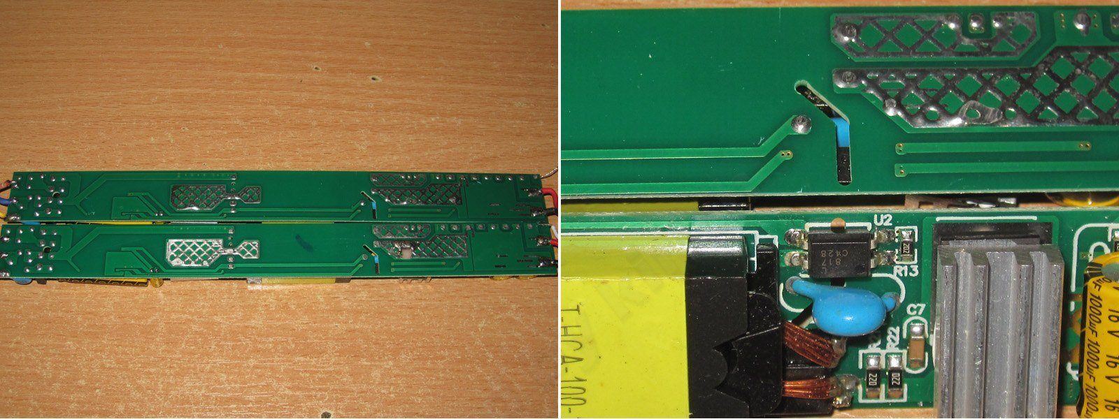
The underside of the board is clean and tidy. The safety features are also well thought out: not only is there plenty of clearance, but there’s also a slot. It feels like this board was laid out by a completely different person—someone who’s clearly an engineer. The output has a bank of small capacitors rather than one large one, and there’s a synchronous rectifier.
Overall, it’s already clear that this is a power supply in a different league.
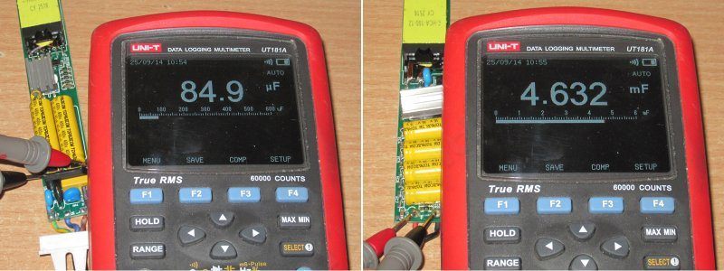
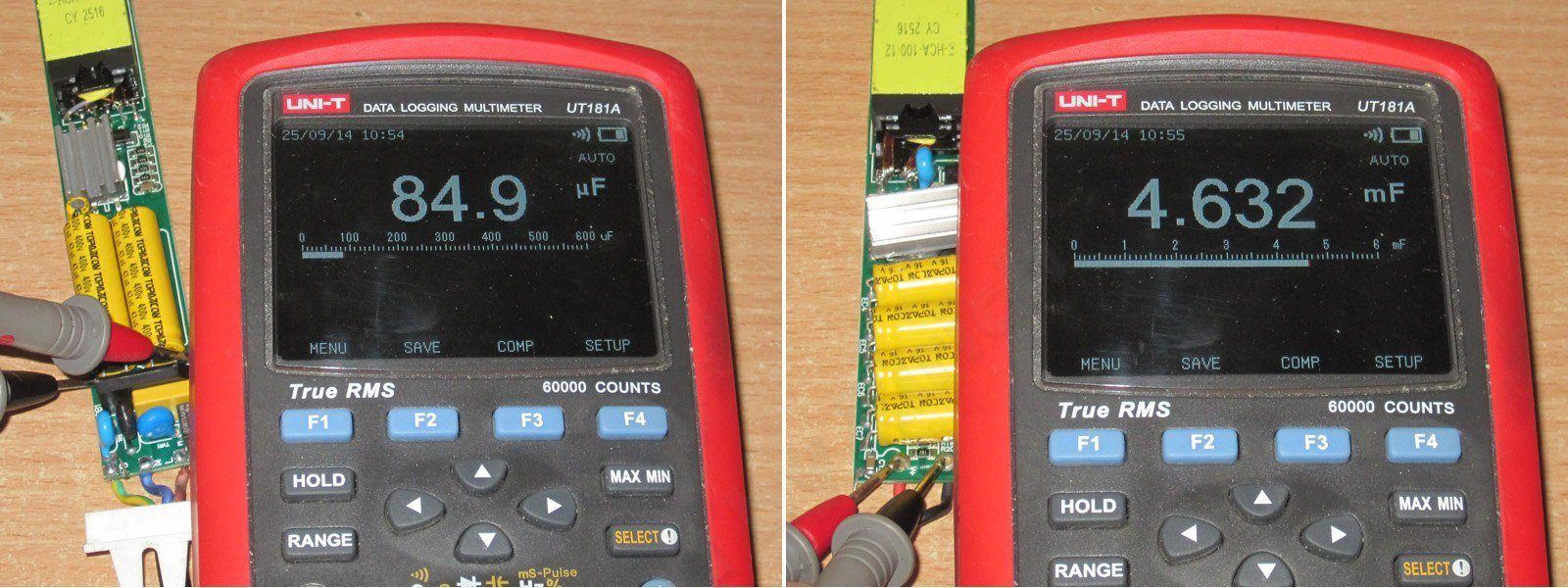
The actual input capacitance is 85 µF, somewhat short of the claimed 94 µF, but still quite sufficient. The output capacitance is noticeably higher than specified; it could have been higher still, but it’s enough as is.
Let’s start by testing the HCF-100 model, which has a slightly smaller case.
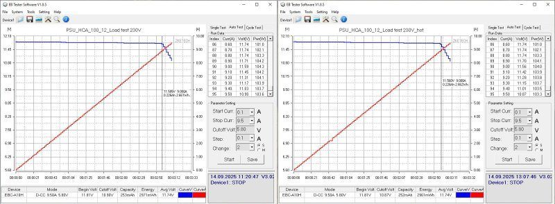
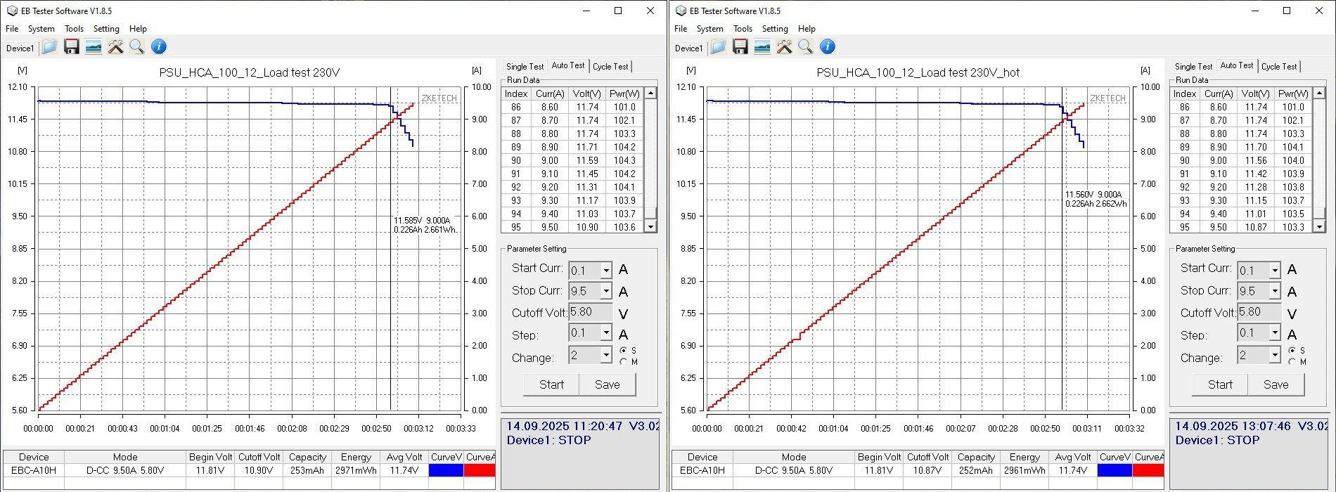
The overcurrent protection kicks in at about 9 A, which is generally fine for the claimed 8.3 A. The protection reduces the voltage rather than shutting the output off completely. There’s no temperature dependence.
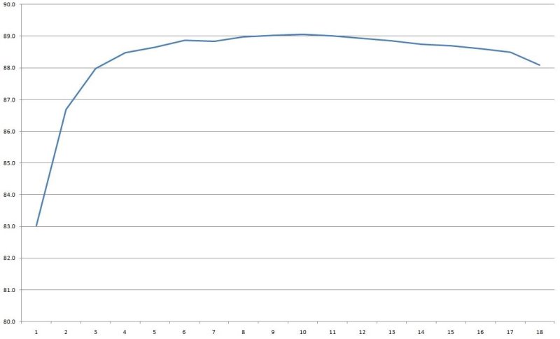
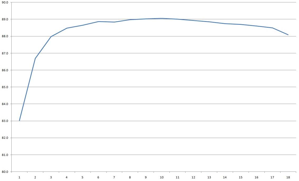
Efficiency reaches 89%. This is a good example of how much difference a single component can make: a synchronous rectifier instead of a regular diode.
Yes, they cost more, but folks, they’re so much better.
The horizontal scale is 0.5 A per division.
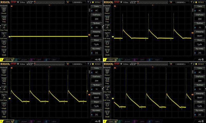
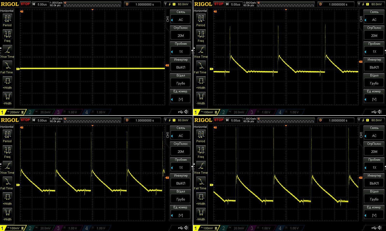
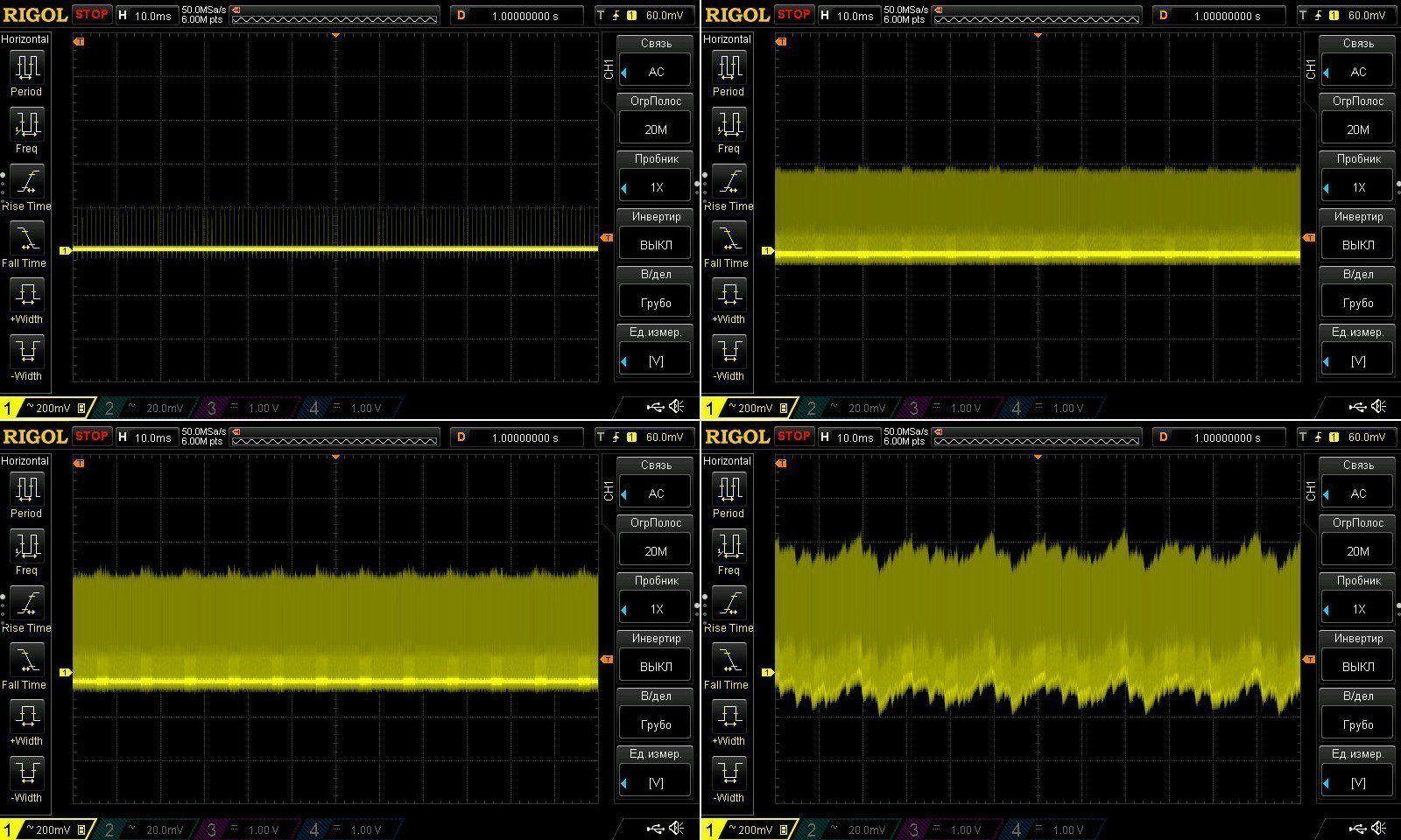
Ripple was checked with no load and at currents of 3, 6, and 9 A.
At 9 A, the main ripple component had an amplitude of about 200 mV. I wouldn’t call that low, but it’s perfectly acceptable, although given the design I expected less.
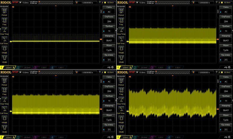
At 100 Hz, everything looked very good up to 9 A. At that point some kind of noise started creeping in, but for the most part I have no complaints about this power supply—especially considering that this was at an overcurrent level.
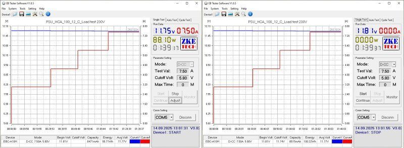
The long-duration test was run at 3, 4.5, 6, and 7.5 A. I have no complaints about voltage stability.
In fact, I’d like to point out how exceptionally stable the output voltage is: it didn’t change by even 0.01 V across the entire range, from no load to 9 A.
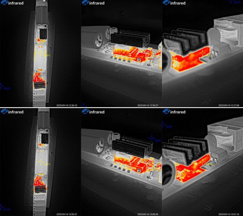
The test results were somewhat predictable, but I’ll go into more detail. At 6 A, everything is excellent, so I’ll move on to 7.5 A.
Transformer: 79 °C, excellent. Transistor: 85 °C, good. Output “diode”: 110 °C, too hot.
I mentioned above that the synchronous rectifier used here is intended for 12 V, 5.5 A power supplies. It works perfectly well at 6 A, but at 7.5 A it’s clearly being pushed to its limit. So, in my view, this is a perfectly good power supply for continuous operation at 6–6.5 A, provided it’s installed in a case.
HCF-100L model.
Although it uses the same board, since this power supply has already landed in my hands, I’ll test it too.
But here’s something interesting: this unit’s overcurrent protection trips at 8.3 A, compared with 9 A for the previous one. That’s too large a difference to put down to measurement error, especially since the shunts in these units are identical. By the way, 8.3 A is actually the claimed maximum for a 100 W, 12 V power supply.
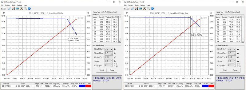
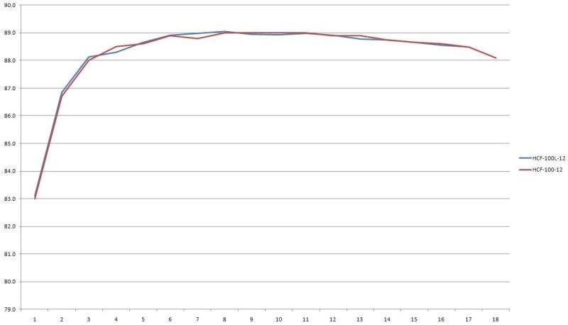
Efficiency is identical, which is what you’d expect. It would be strange if there were differences here too.
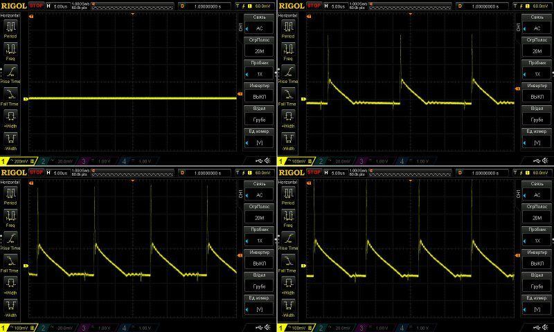
The ripple is essentially the same, although this unit was tested with no load and at 3, 6, and 8 A, rather than 9 A as with the previous one.
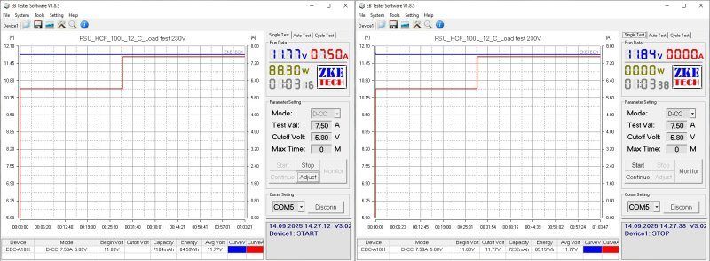
You can see here that at 100 Hz and 8 A, everything is perfectly fine. The previous unit was tested at 9 A, and its protection trips at 9 A. This one was tested at 8 A, with protection set at 8.3 A.

Honestly, I couldn’t be bothered to go through all the thermal soak stages here, so I changed the procedure a little: I loaded it straight to 6 A, then to 7.5 A. The total test time was about an hour.
At 7.5 A, the transformer was at 81 °C, the transistor at 88 °C, and the output rectifier at 112 °C. I got roughly the same results with the previous unit.
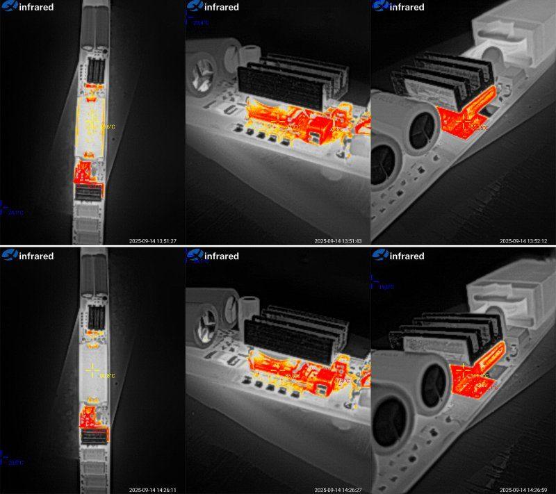
Later, I decided to take a photo of what it all looked like after the tests were over :)
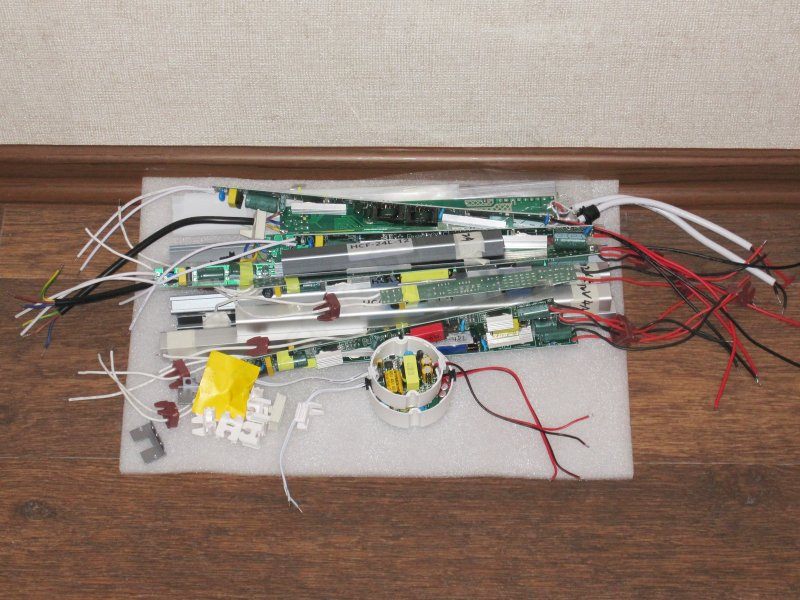
Conclusions.
First, a point that applies to almost all the models, except the 100 W versions: safety. In fact, all 8 models have some kind of electrical safety issue, some more serious than others. That’s why I want to stress that these power supplies should only be used where neither the power supply itself nor any of its electrical circuits—on either the input or output side—can be accessed. I also recommend grounding the power supply output and observing the correct input polarity: always connect the live wire to the input terminal with the fuse.
The 100 W models have almost no safety issues. The only thing that could happen is the heatsink coming loose from the transistor. By the way, these are the only power supplies in the test whose input cable not only has the live wire clearly marked, but also includes a ground wire. That’s exactly why I decided that an engineer must have designed it after all, while the 100 W rating came from a marketing person.
I should also mention the rather odd case design on some models: steel, with a wide slot. I’ve never seen anything like it.
I almost forgot: all models except the 100 W ones use capacitors rated for an upper temperature limit of 130°C. That’s certainly impressive, but their sizes are also rather odd: capacitors with the same capacitance differ in size, while ones with very different capacitance are almost the same size. That’s why I have doubts that the capacitors are really rated for 130°C.
Now, the individual models.
HCF-18L and HCF-24L. I’d call these relatively decent. At least they deliver their rated power, and they’re built around an integrated PWM controller, which also provides overtemperature protection. Ripple is acceptable, and so is stability. Setting aside the safety issue, these are pretty good little power supplies.
HCF-36L and HCH-48L. These are worse. As I mentioned, I wasn’t happy with their interference. In other words, their ripple is acceptable, but they generate a lot of RF noise, which is not good and can also interfere with devices that use microcontrollers.
The 36 W model runs at a reasonable temperature, but the 48 W model overheats. It also starts reducing its output voltage at 4 A, so if you use it, it’s best not to load it to the limit. Honestly, I didn’t like either of these models, mainly because of the interference.
HCA-48 and HCA-60. Although these models look identical on the outside, they’re very different inside. The 48 W version has overheating problems; in reality, it’s good for 36 W at most. The 60 W version does better, but it’s really closer to 50 W, and its ripple is fairly high. Both models also have a strong load-dependent output voltage, especially the 48 W version. And instead of a fuse, both power supplies have a resistor on the input. It’s probably a fusible resistor—a hybrid of a resistor and a fuse—but I much prefer the thermistor-plus-fuse arrangement.
HCF-60L. Essentially, this is almost identical to the HCF-36L and HCH-48L: the same PWM controller and the same interference. That’s why I don’t recommend it, even though its ripple and temperature performance aren’t bad. Its maximum power, however, is no more than 45–50 W.
HCA-72. This is somewhere between the HCF and HCA models shown earlier. It doesn’t have the kind of interference seen in the HCF-60L. There is some ripple, but it’s tolerable. It runs fairly hot, so in reality this is more of a 60 W power supply than a 72 W one. But the biggest complaint is its safety; everything else is tolerable.
HCF-100 and HCF-100L. As I wrote, these are the same power supply, although I was a little surprised by the difference in their overcurrent protection thresholds. Overall, they’re quite good in almost every respect. My only real complaint is the rated power: in reality, these are more like 70–80 W power supplies; anything higher is just a marketing person’s dream. I liked both the circuit design and the components, as well as the low ripple, excellent output voltage stability, and fairly high efficiency. Overall, I can recommend them, as long as you keep the actual power rating above in mind.
So, in brief:
HCF-18L and HCF-24L are decent, but have poor electrical safety.
HCF-36L, HCH-48L and HCF-60L. I don’t recommend them, mainly because of the combination of poor safety and very high interference levels, even though they passed some of the tests reasonably well—not perfectly, but acceptably.
HCA-48 and HCA-60. It’s a mixed bag. Yes, they have safety issues, but they should be usable at reduced power. There are some concerns about overheating, though; overall, they feel a bit rough around the edges.
HCA-72. If you can overlook the poor safety and reduce the load from 72 W to 55–60 W, it’s actually quite decent.
HCF-100 and HCF-100L. These were my favorites. They don’t have many drawbacks, really: one is that the heatsink could come loose and short something inside; the other is that the power rating is overstated. In reality, these power supplies are good for 70–80 W at most. Still, they’re very good.
That’s probably all for today. This review turned out rather long and a bit... exhausting, but I hope it’ll be useful. And of course, thanks to Vitaly for providing these samples of Chinese industry for testing :)
A reminder: to keep up with new posts on the blog, I recommend following me on Instagram. I’ll post notifications about every new article there, and might also write about something interesting now and then - link to the account
You can also subscribe to updates and new articles on the Telegram channel - https://t.me/KirichBlog
I’ve already published a review of the HCF series power supplies, but those were round, while these are “thinner, but longer.”
I won’t include links to them, since these are test units sent over to check what a particular factory actually makes and whether it’s worth doing business with them.
The first thing that stands out is the unusual form factor: these power supplies really are thin. Though I’m not even sure what to call them, since “thin” refers to thickness, and they’re narrow as well.
There are 10 power supplies in all. Two of them look more conventional, although they belong to the same series; I just decided not to give them their own article.
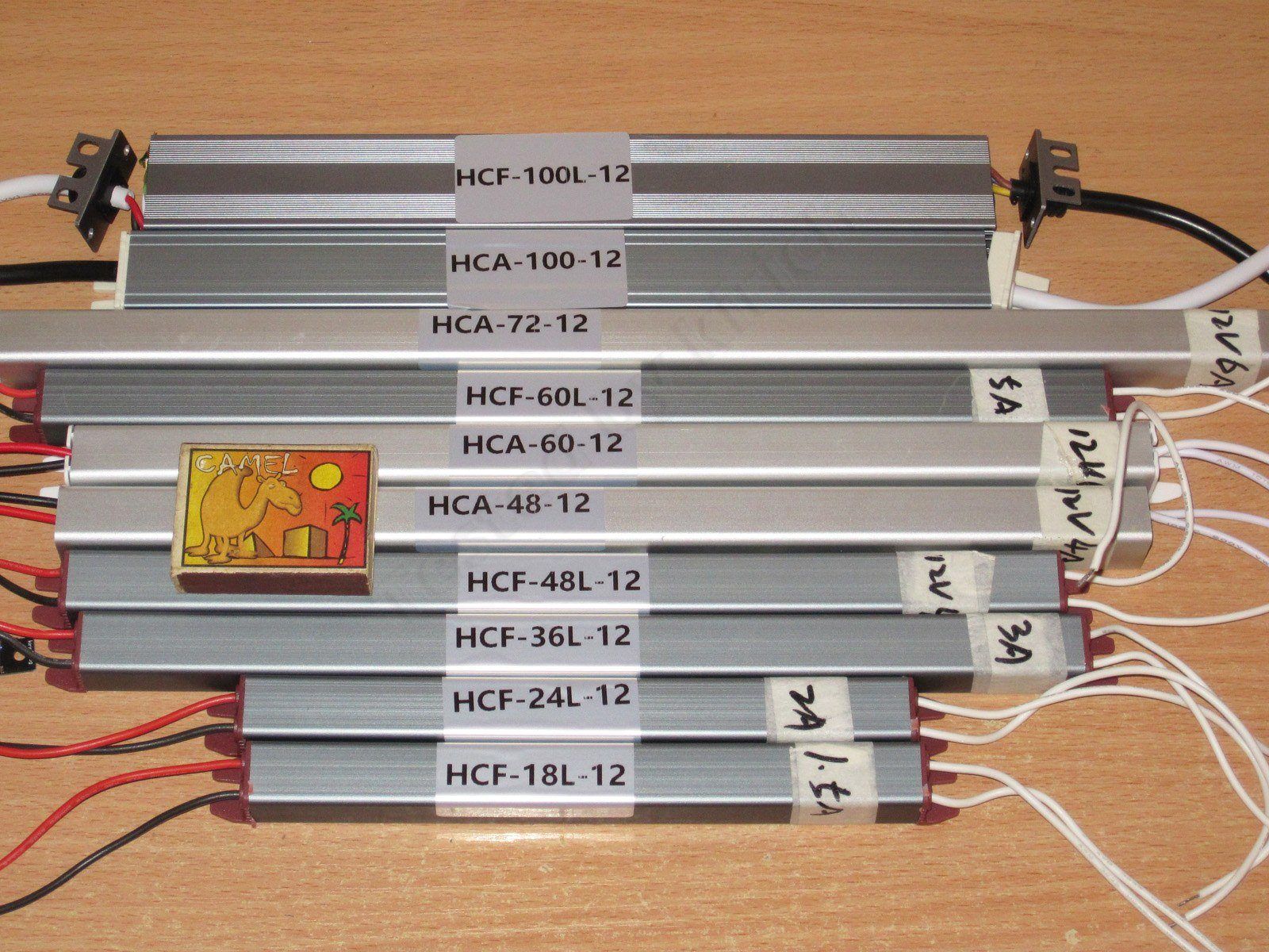
I’ve grouped all the power supplies into pairs, since most differ mainly in power rating. At least one pair is shown together simply “to keep the paperwork in order.”
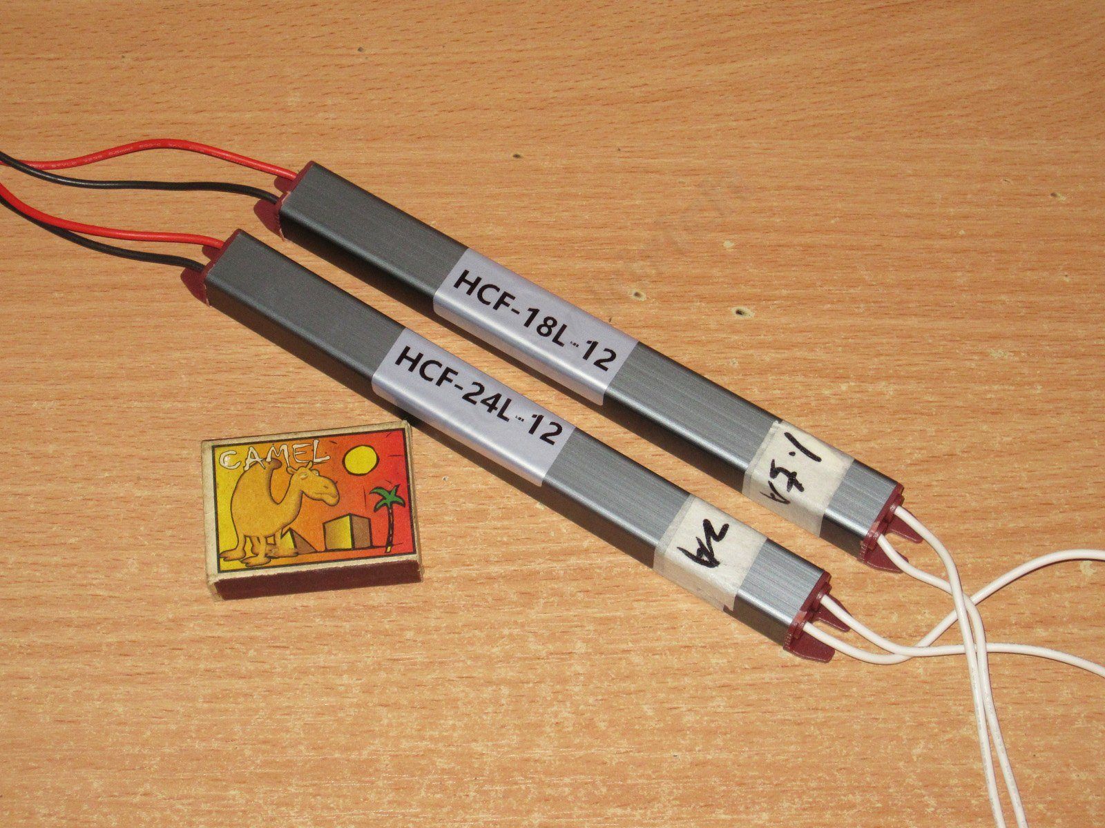
I’ll start with the two smallest models, rated at 18 and 24 W, or 1.5 and 2 A, respectively.
The cases are 175/195 mm long, with a 17 × 14 mm cross-section. The wires have silicone insulation.
Even I’m struggling to come up with a name for this kind of case design. On the one hand, it is technically a case, but it has a fairly wide gap running its entire length, which is not very safe. That’s a fact too. And the case appears to be made of steel.
There’s a board running the full length inside. It has an insulating sheet, but only underneath the board. I don’t know, but this design makes me uneasy.
The layout is relatively spacious, but the board is so narrow that there are a few things to complain about. By the way, the PCB material in most of these power supplies is very thin. I didn’t measure it, but it’s definitely under 1 mm, so the boards in the longer models literally bend in your hands.
Visually, the boards are identical, except perhaps for the color of the transformers.
There’s no input choke, but there is an X capacitor, a thermistor, a proper fuse, and even a varistor rated, I think, for 510 V peak.
The input capacitors are 10 and 15 µF, depending on the power rating, but what surprised me is that they’re rated for 130°C!
The output capacitors also differ: 680 µF in the 18 W model and 1000 µF in the 24 W model. They’re also rated for 130°C.
I can’t say for sure whether these capacitors are really rated for that temperature or whether it’s just a nice-looking label on the heat-shrink sleeve. But I can say this: I’ve more often come across capacitors rated for 125°C. They were marketed as long-life, but not low-impedance. They’re perfectly suitable as input capacitors, but not always as output capacitors.
They use a fairly decent integrated PWM controller: the 18 W model has a DK112, while the 24 W model has a DK125. There’s a catch here: according to the datasheets, the first is rated for 12/15 W and the second for 24 W, so the first one will be overloaded.
In principle, that’s not a problem, since these controllers have built-in thermal protection and should simply shut down in the worst case. The real problem is that the feedback optocoupler is on the hot side, a long way from the rest of the circuit, so the “cold-side” traces run very close to the “hot-side” traces.
Grounding the output could solve this problem, but there’s another catch: although the board marks the live input terminal, and the fuse is installed on that input, the input wires themselves aren’t marked. With these models, you can more or less peer through the gap to see which wire goes where, but that’s a pretty clumsy solution...
The point is that if you ground the output, the input polarity must be such that the fuse is on the live wire. If there are no markings and you can’t connect the power supply with 100% certainty, the right thing to do is install two fuses.
So this power supply should only be used in designs where, first, the power supply itself isn’t freely accessible, and second, neither the input nor output live parts are accessible. Such designs do exist, but they’re rather specialized.
The underside of the PCB also shows that one of the copper pours connected to the output is very close to the transformer’s input pins. Although the large copper pour itself doesn't serve much purpose here, since there is a narrow section near the output diode—the very component the pour is supposed to help cool.
Measured capacitance of the input and output capacitors for the first and second power supplies, respectively. The input capacitance is a little on the low side. It should be fine at 230 V, but at 115 V the PWM controller will have a harder time.
As usual, I use an EBC-A10H battery tester to check low-power supplies. For the efficiency test, I used an electronic load based on a CL24 board.
The 18 W model's protection trips at 1.7–1.8 A, whether the supply is cold or hot. Output voltage stability is quite good.
Efficiency is 83–84%, which is pretty typical. The scale at the bottom is in 0.2 A increments.
Ripple with no load and at 6, 12, and 18 W. Pretty much as expected: at maximum power, most of it is around 300 mV. That's probably tolerable, and should be fine for undemanding applications such as LED lighting.
The low-frequency ripple is actually quite good; there's practically no 100 Hz component.
I checked the temperature rise at 0.5, 1, and 1.5 A.
The power supply's output voltage has a slight positive temperature coefficient. It started at 11.98 V when cold and ended at the same 11.98 V after warming up, ultimately compensating for the voltage drop in the wires. The power supply itself dropped by 50 mV as the load changed from 0 to 100%.
A note: here and below, unless otherwise specified, measurements were taken at the output wires, which slightly affects the output voltage under load. When measuring efficiency, I monitored the voltage directly at the power supply output, so I could see how well it actually maintains its output voltage.
At 1 A, temperatures were well within the normal range: the PWM controller was at 50°C, the transformer at 45°C, and the diode at 61°C.
Again, because it's difficult to measure temperatures with the unit closed up, I had to measure the bare board lying on the table. I expect temperatures to be higher once the board is installed in the enclosure. The point is that in similar power supplies filled with potting compound, a significant amount of heat is transferred to the enclosure, improving cooling. Here, by contrast, although the enclosure is metal, heat reaches it through the air.
At 18 W, everything also worked well: the PWM controller was at 61°C, the transformer at 55°C, and the diode at 77°C. There's even a decent amount of headroom.
The 24 W model, which also has a 24 W controller, shut down at 3.5 A. That's rather crude given its stated maximum of 2 A. But as I mentioned, the chip has thermal protection, so there's no real cause for concern. In my own experience, I've only come across one power supply using this PWM controller that failed.
Efficiency is slightly higher, probably thanks to the higher-capacitance input capacitor and the PWM controller and transistor, which have lower resistance.
The scale at the bottom is in 0.2 A increments.
The high- and low-frequency ripple is almost identical to that of the previous power supply, so the recommendations for use are the same. I tested it with no load and at 0.7, 1.4, and 2.1 A.
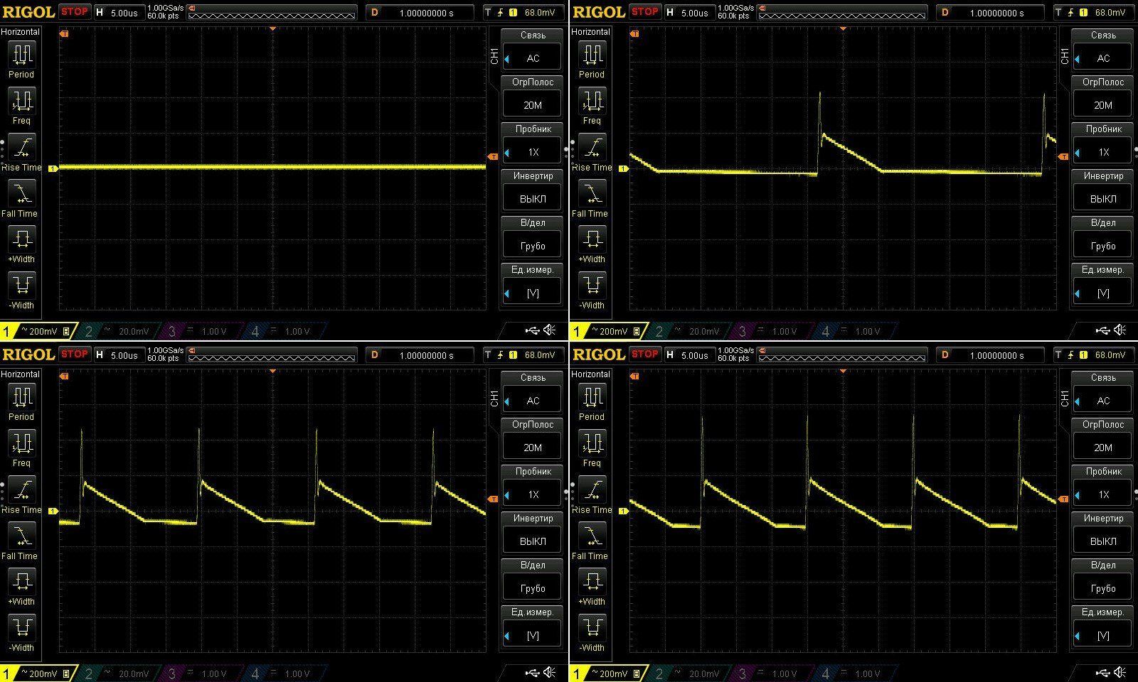
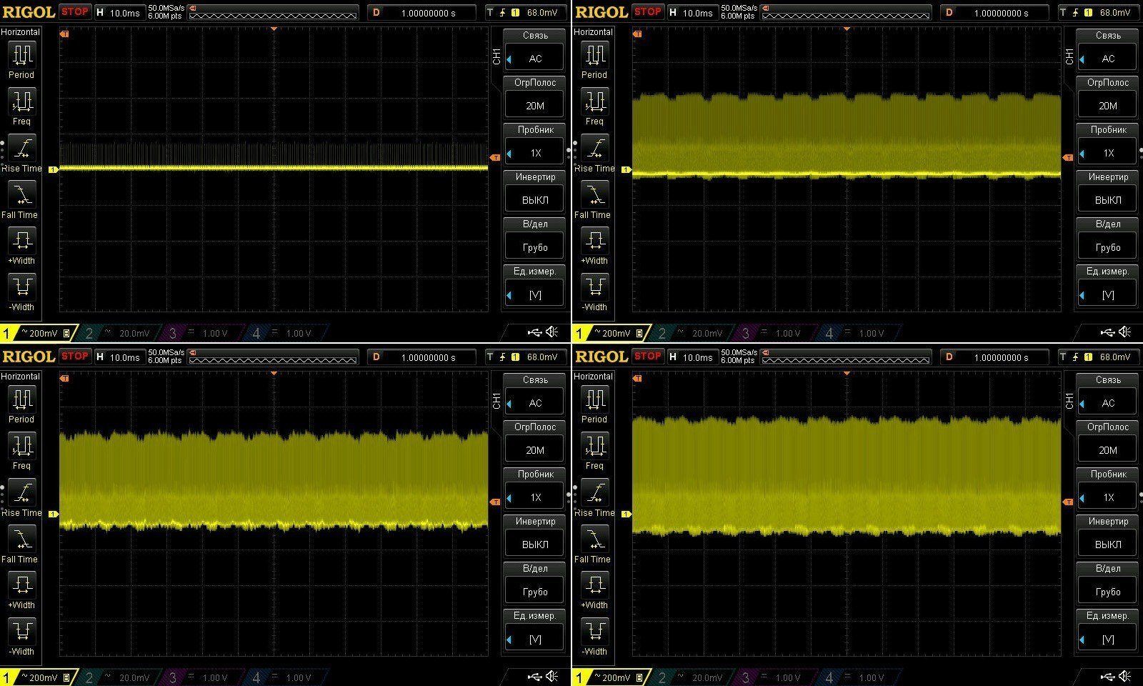
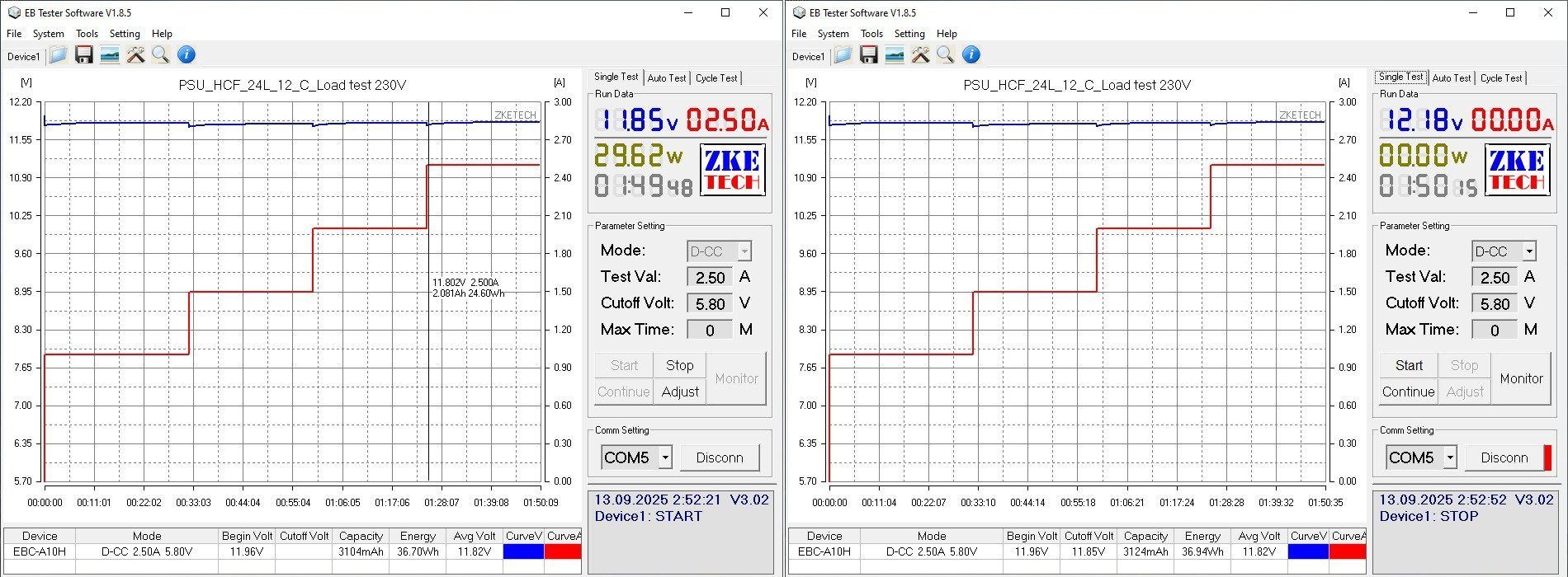
I checked the temperature rise at 1, 1.5, 2, and 2.5 A, so even with a noticeable overload. It behaves just like the previous model: the graph shows steps where the voltage sags under load, then rises slightly as the unit warms up.
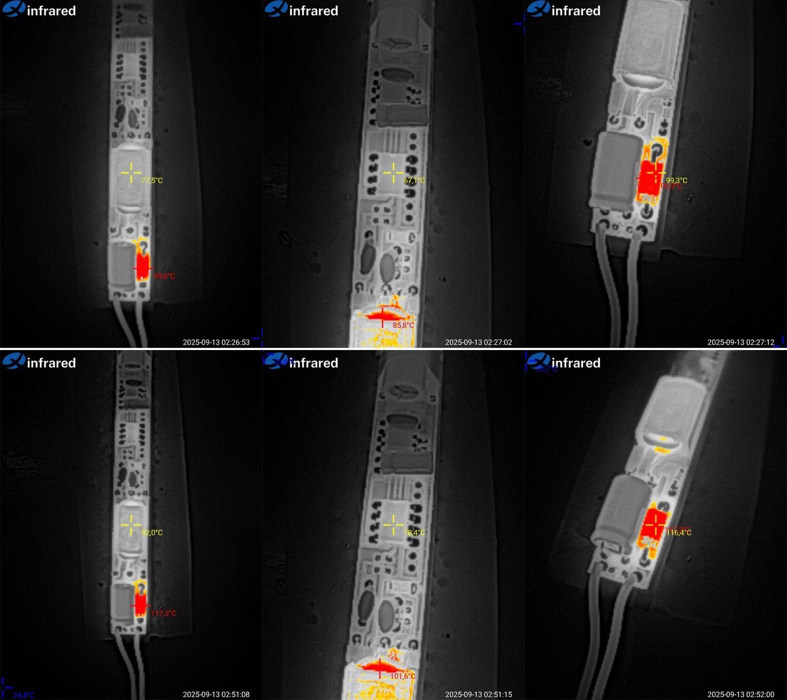
Temperatures at load currents of 2 and 2.5 A.
At 2 A (100% power), everything is quite normal: the transformer is at 77°C, the PWM controller at 67°C, and the diode at around 100°C.
At 2.5 A, things got a little worse: the transformer was at 92°C, the PWM controller at 78°C, and the diode at 117°C. The only real concern is the diode temperature; the other components still have a little headroom.
Overall, I think the temperatures are fine here, with a little headroom for installation in an enclosure and for higher ambient temperatures.
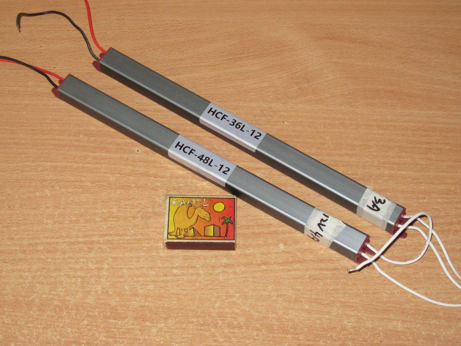
Next up are the HCF-36L and HCF-48L models, rated at 36 and 48 W, or 3 and 4 A, respectively.
Length: 263/283 mm; cross-section is the same as the previous models, 17 × 14 mm. Silicone-insulated wires; essentially, compared with the previous ones, the only visible difference is their length.
The design is absolutely identical to the previous models. In fact, these power supplies are almost the same.
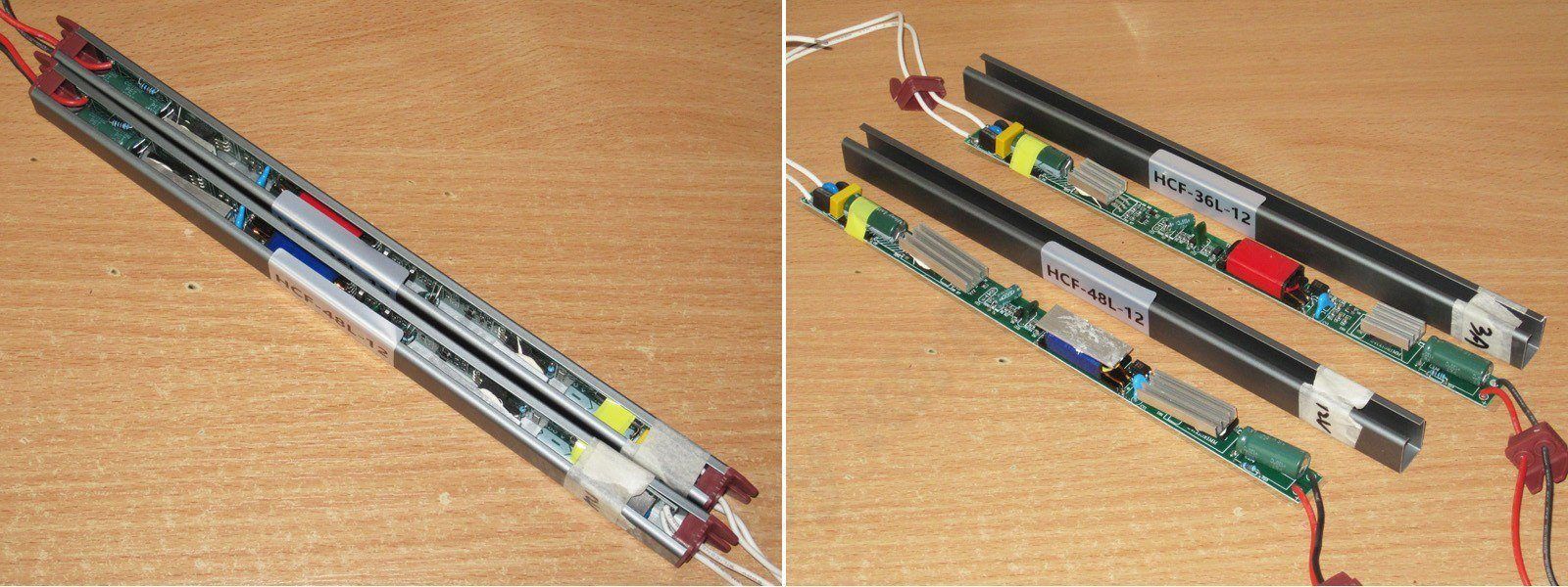
Visually, the boards differ in their larger heatsinks and the aluminum plate on the transformer in the 48 W version.
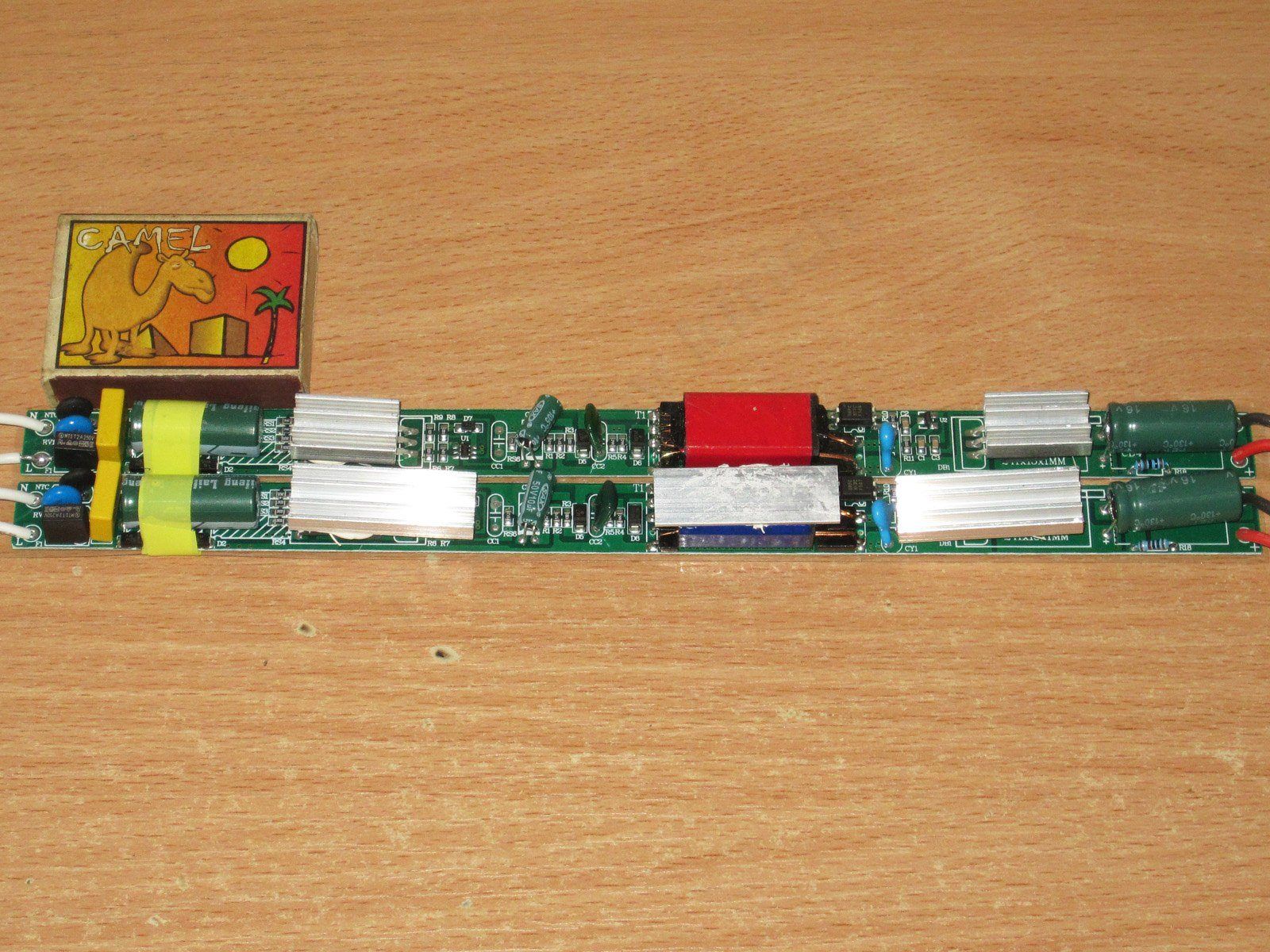
The input has an X capacitor, thermistor, varistor, and fuse, but no inductor.
I found one more difference: the current-sense shunt resistance is different. The 36 W model has 2.2, 2.2, 2.4, and 2.4 Ω resistors, while all four in the 48 W model are 2.2 Ω, which gives it a slightly higher protection trip current.
The transistors and diodes could theoretically be different too, but for some reason I seriously doubt it.
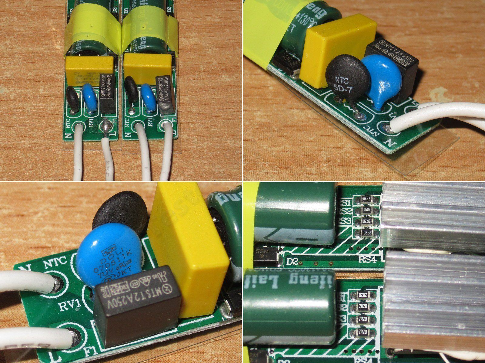
It uses a PWM controller marked 30509; in the 48 W version, it is simply hidden under the heatsink. The optocoupler is now in the right place.
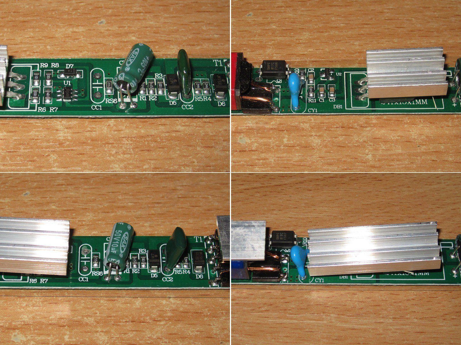
The input capacitors are 22 and 33 µF, but interestingly, they are almost the same length. The output capacitors are 2200 and 3300 µF for the 36 and 48 W versions, respectively.
These also use capacitors rated for 130 degrees.
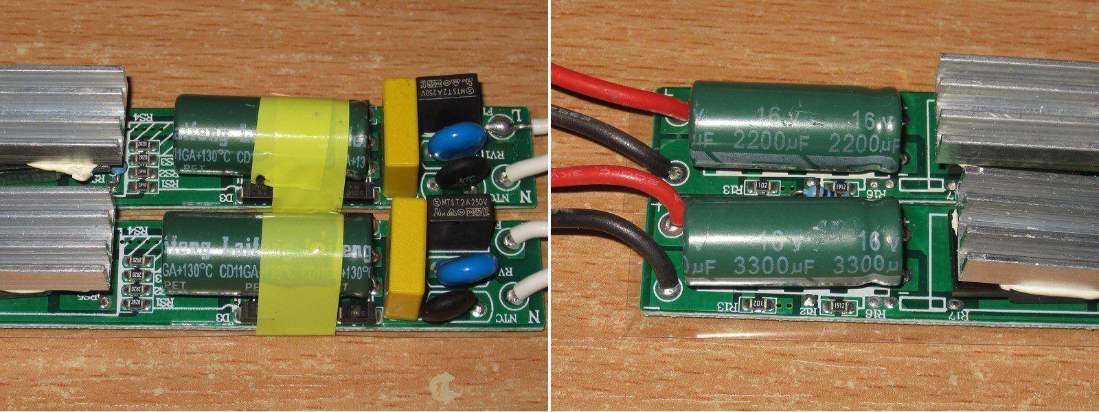
The PCB layout here isn't ideal, but it's noticeably better than on the previous model.
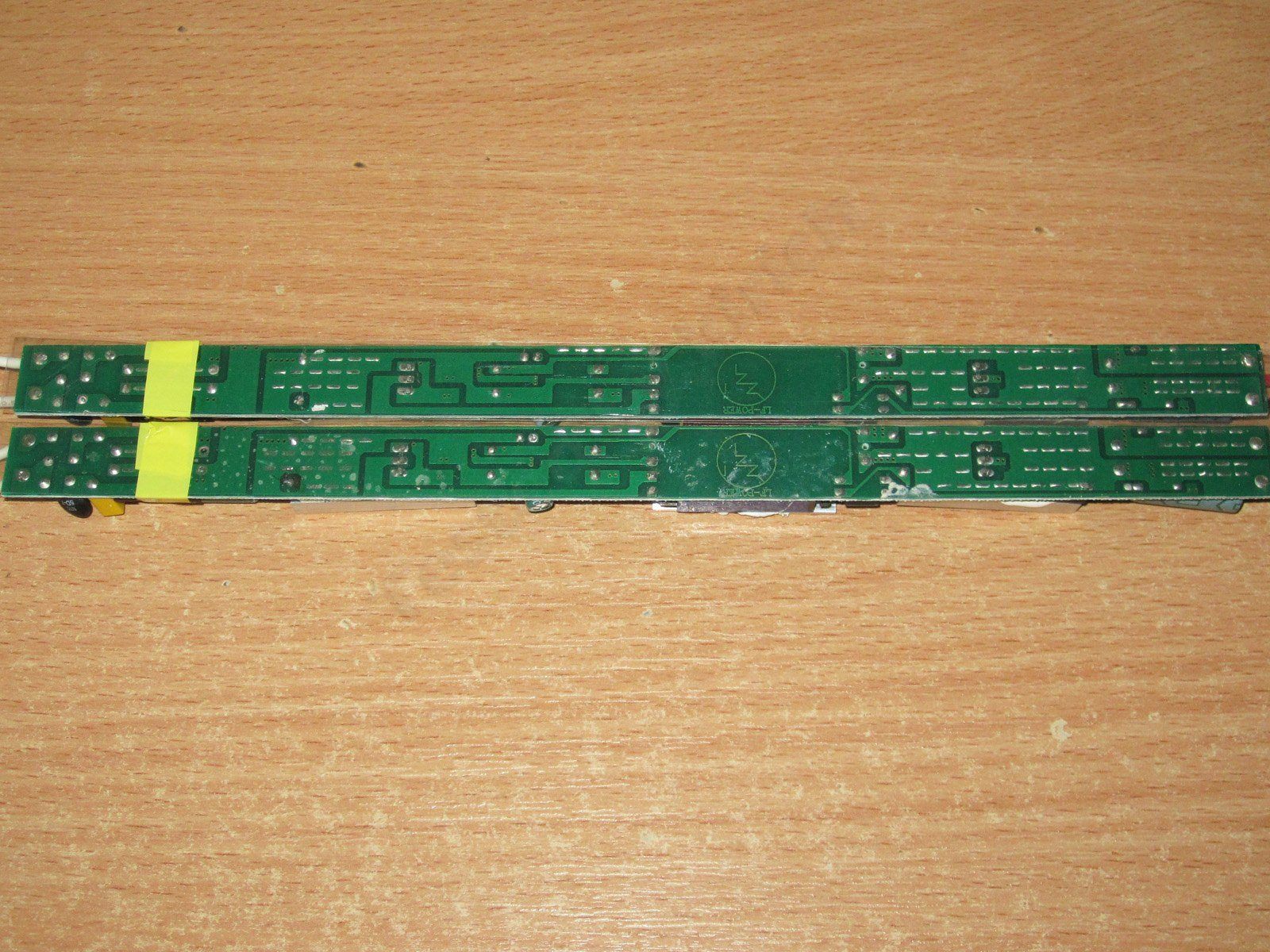
The thing is, the clearances are still small. The photo shows the Y capacitor, with the optocoupler pins below it.
I think that if the trace layout were changed slightly, as marked in red on the lower board, and one of the traces to the optocoupler LED were routed on the top side, things would be not exactly good, but noticeably better than they are now.
Overall, my recommendations for this model are much the same as for the previous one: either prevent contact with the output wires (by using a fully enclosed case), or ground the output, making sure the input is correctly phased. Or do both.
Input and output capacitance for the 36 and 48 W power supplies, respectively.
I have no concerns about the output capacitors, but the input capacitance is a little low. As before, it's fine for 230 V, but not enough for 115 V.
The protection trips at around 3 A, regardless of the power supply's temperature. In other words, the protection threshold is set very close to the limit here; perhaps that's a good thing. The protection is gradual, though: under overload, the output doesn't shut off immediately, but the voltage simply drops. Personally, I like this approach less, but a lot depends on the type of load.
The output voltage is very stable. Ignoring the voltage drop across the wires, the difference was 30 mV.
Efficiency is 83–84%; the scale at the bottom is in 0.2 A increments.
High-frequency ripple is around 300 mV at maximum current. Measurements were taken with no load and at currents of 1, 2, and 3 A. There are spikes, but they are usually easy to suppress with the wires to the load.
At low frequencies, things looked somewhat worse, with noticeable spikes at 100 Hz.
It also turned out that this power supply generates a lot of interference. I could literally hear it through the speakers of the computer the electronic load was connected to.
And at times, the high-frequency ripple waveform looked pretty ugly, too... It felt like the circuit was going into some kind of self-oscillation.
The ripple even affected the connection to the PC. In the screenshot above, you can see that the load wasn't increasing the current very evenly.
At first I couldn't figure out why this was happening. Then I realized that the high level of output noise relative to ground was causing communication errors between the load and the PC, so the whole setup was behaving incorrectly.
I had to install an isolator. Strangely enough, it didn't make much difference to the interference, but the graphs looked a little better afterward. That was during testing of the next power supplies, though. Plus, because of some safety concerns, I didn't want to fry this computer too, as happened with the previous one.
The temperature test was carried out in four stages, at 2, 2.5, 2.9, and 3 A. I split the last test into stages because I was worried the protection might trip, and wanted to test it all in one go.
But everything went fine, and the power supply then ran at 3 A.
The voltage is practically unaffected by temperature. It does vary with load, but that's probably due to the voltage drop in the wires; the power supply itself regulates the voltage well.

And here are the temperatures, with results at 2.9 and 3 A. I'll comment on the maximum-load results.
Transformer: 71°C, excellent; transistor: 55°C, excellent; output diode assembly: 102°C, a bit high, but tolerable.
The protection on the second unit is set up better: 4.2 A when cold, around 4–4.1 A when hot. I also had no complaints about voltage stability, with about 40 mV at the power supply terminals across the full range.
Efficiency is slightly lower, closer to 83%. The horizontal scale is in 0.5 A increments.
Ripple is a little higher: at maximum current it was around 400 mV here, versus 300 mV on the previous unit. At low frequencies, there are the same 100 Hz spikes and the same radio interference.
With a sustained load, though, things are a little different. The power supply performed perfectly at 2 and 3 A, but after I raised the current to 4 A, the voltage gradually started to drop. I think that's because the output current depends on temperature, so I effectively hit the power limit.
After that, I reduced the load current to 3.8 A, and the voltage returned to normal.
Component temperatures at 4 and 3.8 A.
There isn't much difference, so I'll give the readings at 3.8 A: transformer around 100°C, transistor 52°C, diode assembly 117°C.
In my opinion, 3.8 A is too much for this model. The actual maximum continuous output current is closer to 3.5 A, and taking into account installation in an enclosure and some headroom for ambient temperature, I wouldn't recommend loading it above 3 A.
I recently discussed inaccurate temperature measurements with an infrared thermometer, and this is a good example of how readings depend on the surface material.
A piece of black electrical tape (I recommend matte tape) is stuck to the transformer heatsink. It reads 70°C, but if you point the thermometer at the bare metal, it reads 27°C. Quite a difference.
This is because different materials and surfaces have different emissivity and reflectivity. You can usually adjust the emissivity in the instrument settings, but 0.95 is used as a general-purpose default, so it's often easier to “adjust” the surface than the instrument.
So, simply sticking on ordinary electrical tape helps you measure the temperature of surfaces like these more accurately.
In other words, you can accurately measure the temperature of the tape, and by sticking it onto the object you're measuring, you'll get the object's temperature. Yes, there will still be a small measurement error, but it's negligible.
The third pair: HCA-48 and HCA-60, rated at 48 and 60 W respectively, with currents of 4 and 5 A.
These have a different enclosure design: fully enclosed. But these power supplies aren't potted, even though they look sealed.
The enclosure is 293/313 mm long, with a 17.5 × 17.5 mm cross-section. The wires seem to have plastic insulation, and are quite stiff.
The insulation is a little better here: the board is covered about three-quarters of the way with protective film. In theory, a short could occur in two cases:
1. A transistor heatsink comes loose and connects the enclosure to a trace on the board.
2. A breakdown through the ferrite. Some grades conduct electricity, but this is less likely here because the solder mask on the board and the insulation around the core provide protection.
Although the power supplies look exactly the same on the outside, their internals differ quite noticeably—not just in PCB size and components, but also in board layout. In other words, these are essentially two different power supplies that look the same.
Both boards have a varistor at the input, rated at 560 V peak, I think, an X capacitor, and a resistor that serves as a current limiter and fuse. Overall, this is a bit strange. Even the 18 W versions had a thermistor and a proper fuse, but here they decided to cut costs?
The PWM controller is marked 30513.
The 60 W version has slightly larger heatsinks, but I think they could have made them even bigger. As it is, they transfer heat to the case through the air, which isn't very effective.
What really takes some getting used to is that the 60 W version has two transformers. Well, that's a perfectly valid approach, but it's fairly uncommon. I've often seen this in low-voltage inverters, but this is the first time I've come across it in a power supply.
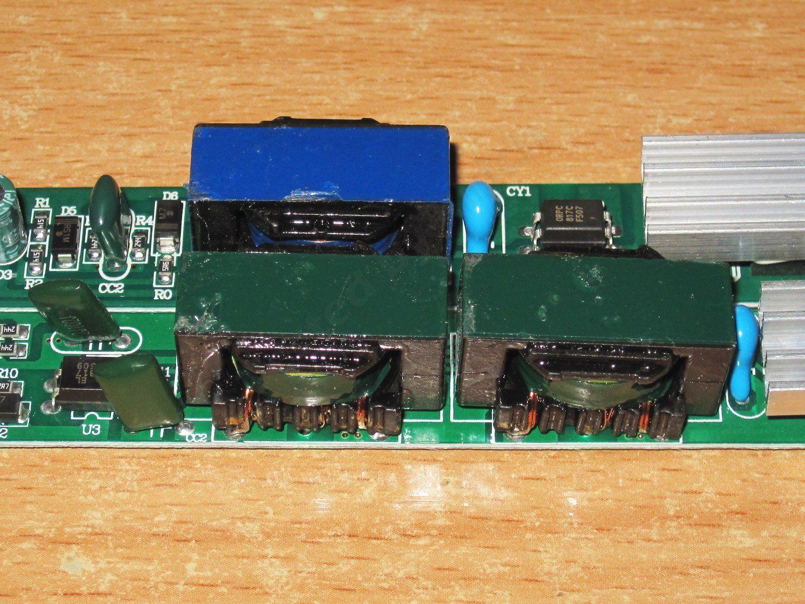
The photo shows that the transformers are the same size. So if the 48 W version has a 48 W transformer, the 60 W version must have 96 W worth of transformers. Or, if the 60 W version has two 30 W transformers, then the 48 W version seems a bit underpowered.
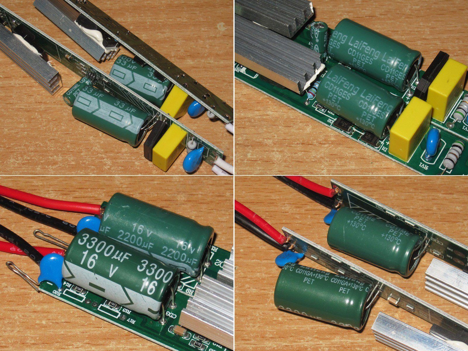
1. Both power supplies have 33 µF input capacitors, again rated for 130 degrees. You can also see here that the capacitors have the same capacitance but different sizes. How do the Chinese manage to make capacitors with the same capacitance in different sizes, yet capacitors with different capacitances that are almost the same size? Naturally, I'm comparing capacitors from the same series.
2. On the output, the 48 W version has a 2200 µF capacitor, while the 60 W version has a 3300 µF one.
I won't complain about the output capacitors, but they could have used a larger input capacitor, at least in the 60 W version. 33 µF is rather small for 60 W, even with a 230 V input.
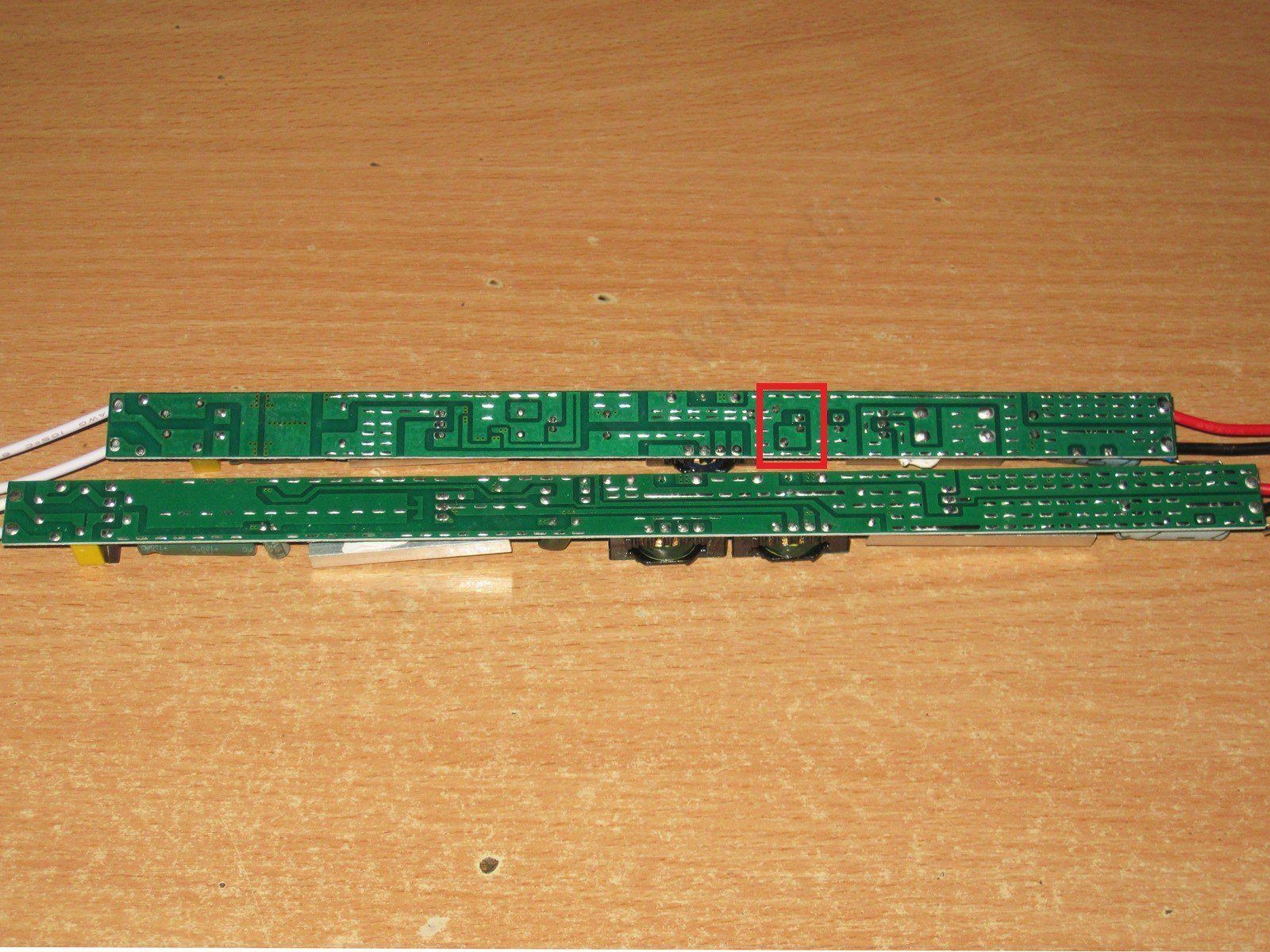
The boards are also noticeably different. About the only thing they have in common is their thickness, which seems to be around 0.7 mm. The 48 W version has a safety weak spot: the copper pour edge is very close to the optocoupler's “hot” side. I think simply moving that copper pour at least 1–2 mm farther away would make it noticeably safer.
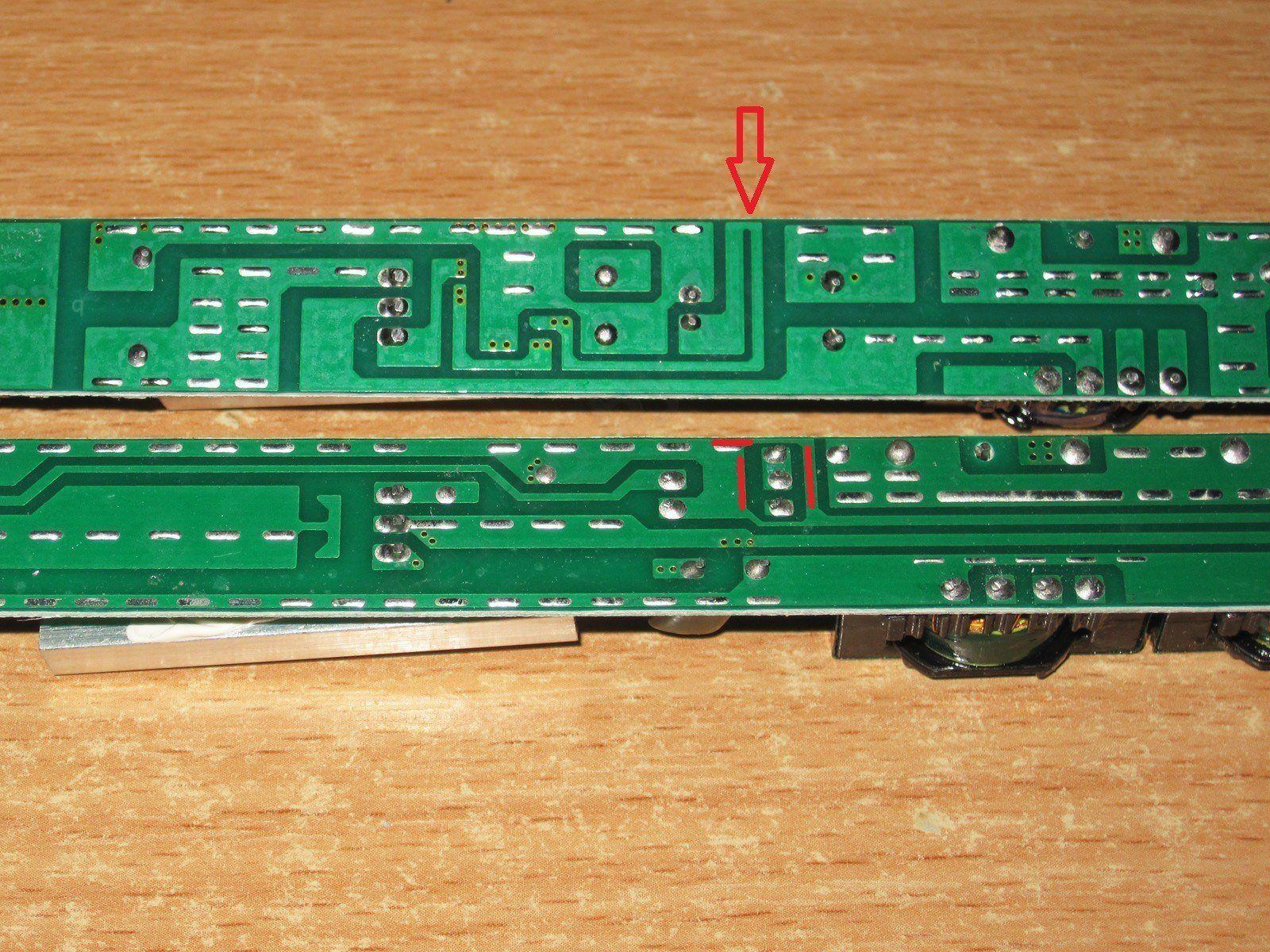
The 60 W model is noticeably worse. First, the optocoupler itself is on the hot side, and the high-voltage traces run right up against it. In short, this is bad.
I also noticed a strange trace on the 48 W version; I can't see what it's for.
The output is as usual: they went all out with the copper pours on the power rails, filling the entire width :)
The measured capacitance is roughly in line with the values printed on the capacitors: 48 W on top, 60 W on the bottom.
The 48 W power supply's protection kicks in at around 4.5 A. When hot, the current is 0.1 A lower, which is normal.
But what surprised me right away was how much the voltage depends on the load.
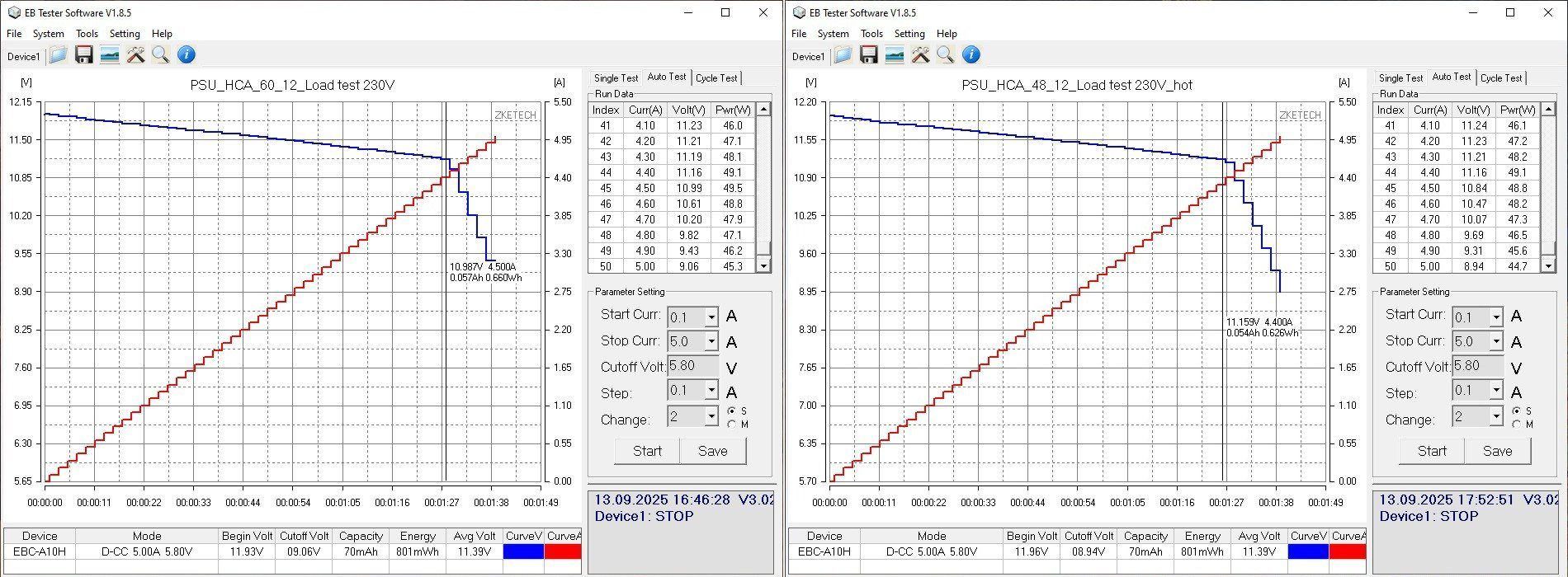
My first thought was that the wires must be really thin, but connecting the load directly to the power supply output didn't improve things much. At full load, the output voltage drops by about 0.8 V, which is a lot.
The screenshot has the wrong model name; it should say 48 W, not 60.
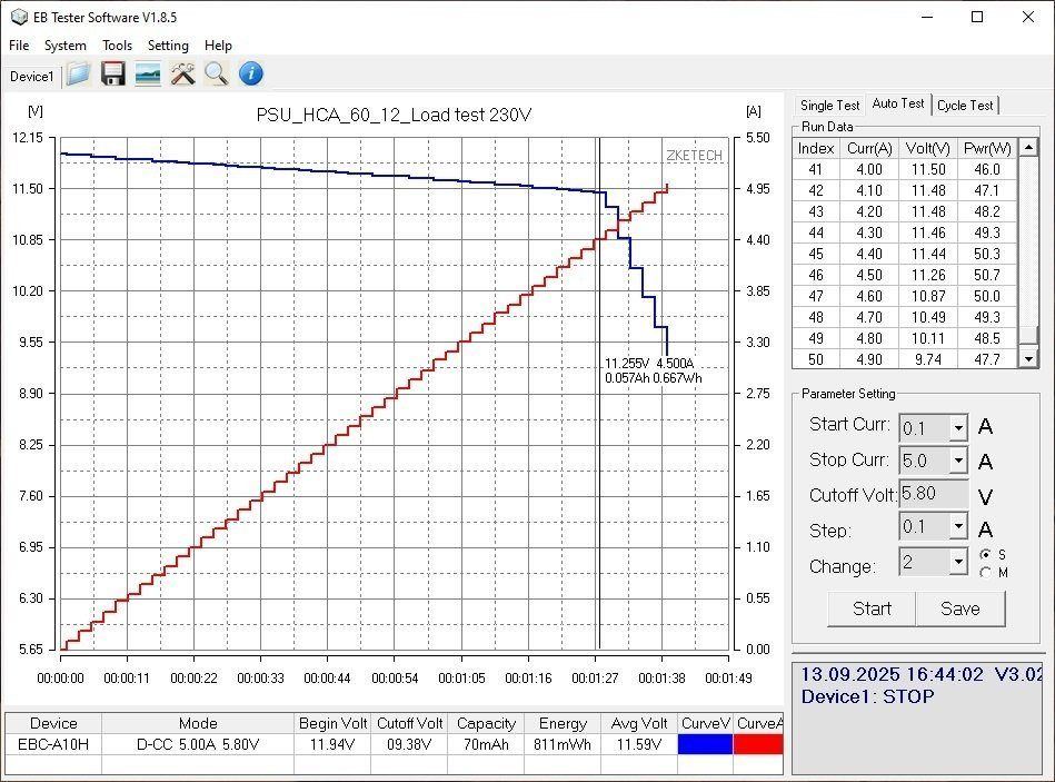
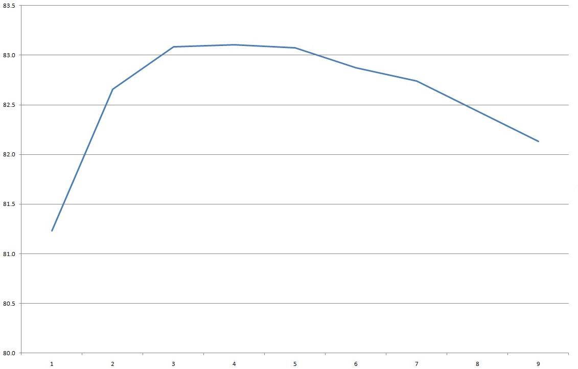
Efficiency is around 83%, but the graph has a bit of a hump to it. The horizontal axis is in 0.5 A increments.
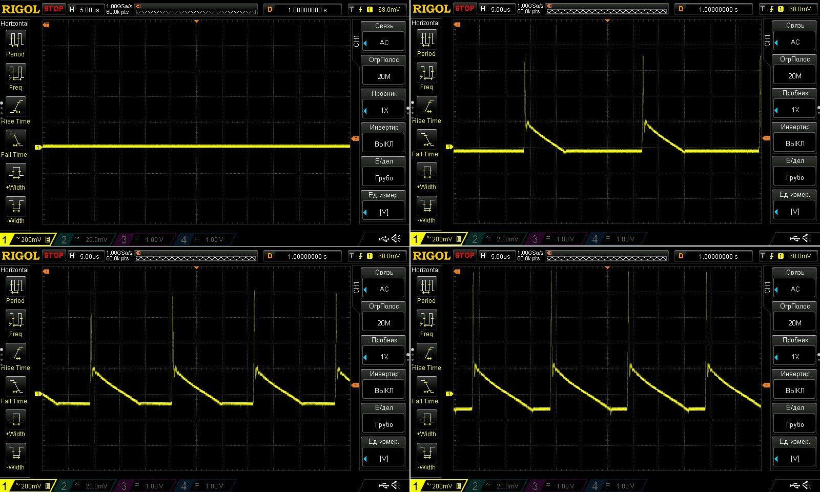
High-frequency ripple with no load and at currents of 1.3, 2.6, and 4 A.
Nothing unusual here: there are spikes, and the main ripple has an amplitude of about 190 mV. Neither good nor bad, just acceptable. Ripple below 1–2% is generally considered normal, which for a 12 V power supply works out to 120–240 mV. But a lot depends on the intended use and the nature of the load.
At low frequencies, everything looks fine. There's no significant 100 Hz component, just general noise, most of which will be “soaked up” by the wires to the load.

The load test was essentially run at three current levels: 2, 3, and 3.5 A. I initially set the current to 4 A, but then reduced it to 3.5 A because things were already getting pretty hot at 3 A.
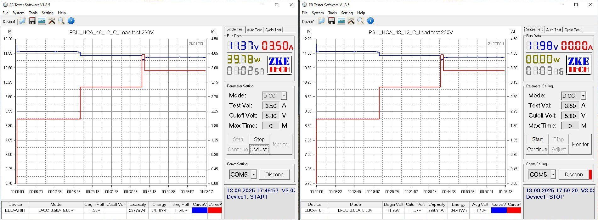
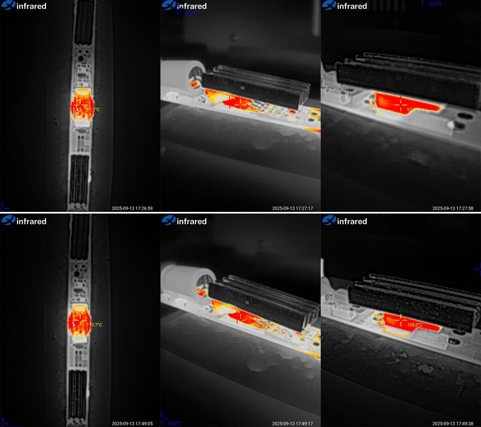
And here are the results.
At 3 A: transformer 95, acceptable; transistor 46, excellent; diode assembly 97, acceptable.
At 3.5 A, things are worse: transformer 114, high; transistor 50, excellent; diode assembly 108.5, tolerable, but at the limit.
Overall, it's clear that even 3 A is a struggle for this power supply. I think that's its long-term maximum in the case at room temperature, mainly because of the transformer temperature.
The 60 W version did better in terms of voltage stability, with a maximum deviation of 80 mV.
But one thing did crop up, more commonly seen in smartphone chargers: the voltage rises under load. The graph shows a sharp increase of about 0.11 V right at the start, followed by a gradual drop as the load increases.
The protection kicks in at a current of about 5.4 A, regardless of temperature.
Interestingly, efficiency is slightly higher here, at around 84–84.5%. I think that's because the two transformers have a lower equivalent winding resistance than the single transformer in the previous model.
The horizontal scale is in 0.5 A increments.
Ripple is a real problem here, though. Below are the results with no load and at currents of 1.5, 3, and 5 A.
At maximum current, the main ripple is around 650–700 mV, or about 5%—that's a lot. It's probably acceptable for LED lights and the like, where the requirements are much less stringent, but personally, I'm not a fan.
At 100 Hz, things are surprisingly fine, apart from the overall ripple, of course. I did notice right away, though, that "green mode" runs at a noticeably lower frequency. It even felt like this wasn't green mode at all, but the power supply had switched to burst mode, since the pulses come at 0.25-second intervals. Perhaps it uses a different PWM controller, or perhaps this is some characteristic of this circuit design and topology.
The load test was run at 3, 4, and 5 A. Voltage does vary with temperature, but only slightly; the load current has a more noticeable effect.
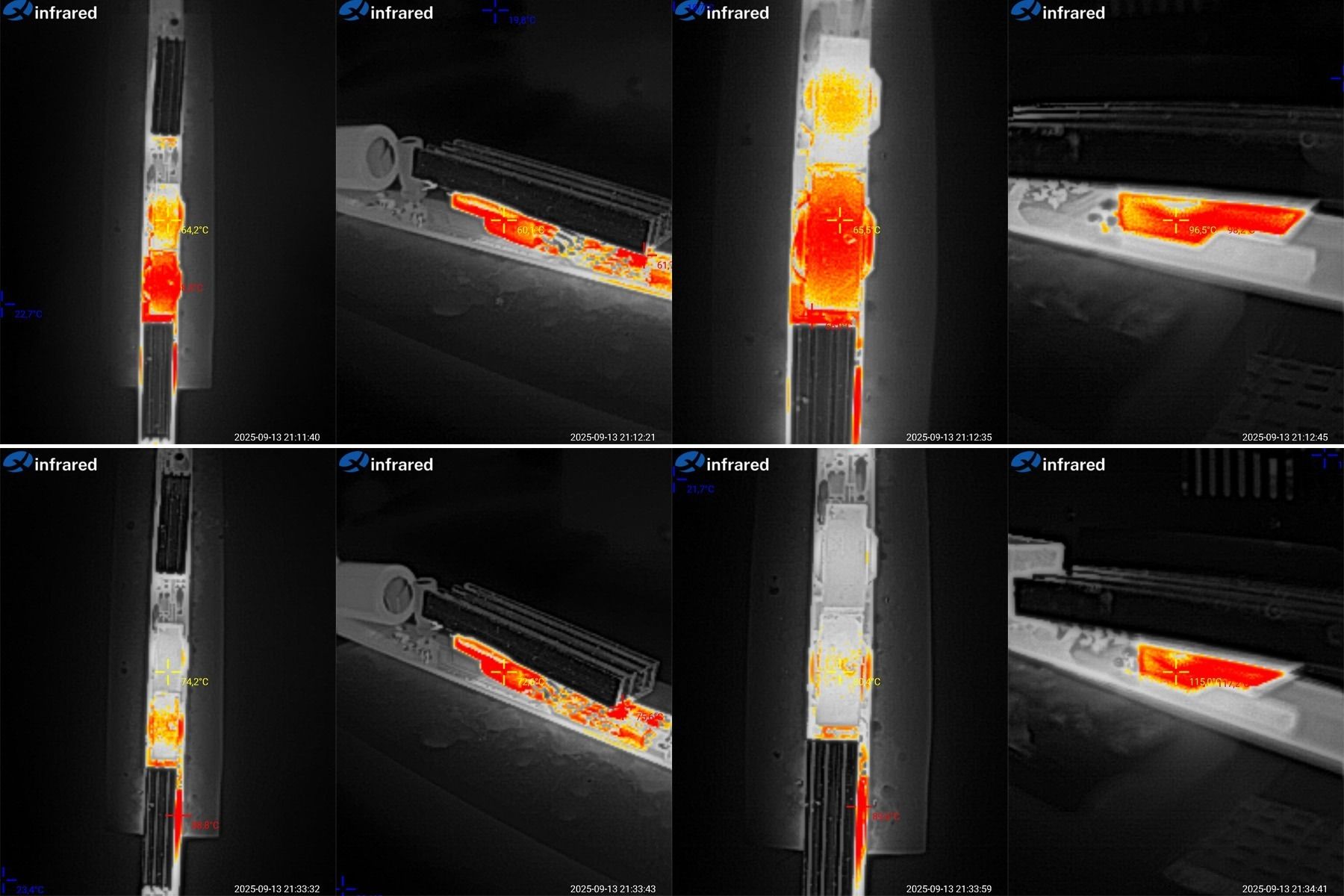
And here are the temperatures at load currents of 4 and 5 A. Just to clarify, by the first transformer I mean the one closer to the power supply input.
At 4 A: first transformer, 64°C; second, 66°C—excellent. Transistor, 60°C—excellent. Rectifier assembly, 96°C—acceptable.
At 5 A: first transformer, 74°C; second, 80°C—excellent. Transistor, 73°C—excellent. Rectifier assembly, 115°C—at the limit; it will overheat inside the enclosure.
So the actual continuous current for this power supply is around 4 A. The low transformer temperatures are reassuring, since they're the most delicate components.
The fourth pair consists of the models that were different in the first place; I've grouped them together simply for consistency.
Models HCF-60L and HCA-72, rated at 60 and 72 W, with output currents of 5 and 6 A, respectively.
Dimensions:
HCF-60L — length 296/316 mm, cross-section 17 × 14 mm, silicone-insulated wires.
HCA-72 — length 357/377 mm (I had to get out the tape measure), cross-section 17.5 × 17 mm, wires with "plastic" insulation.
As you can see, the 60 W model is an extended version of the 18, 24, 36, and 48 W models shown earlier. The 72 W version is similarly an extended version of the 48 and 60 W models from part three.
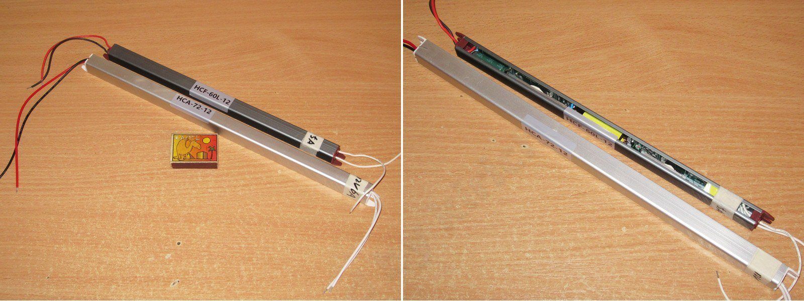
Interestingly, the 60 W model has only one transformer, and its enclosure has a smaller cross-section than the previous models. The 72 W model, on the other hand, has two transformers.
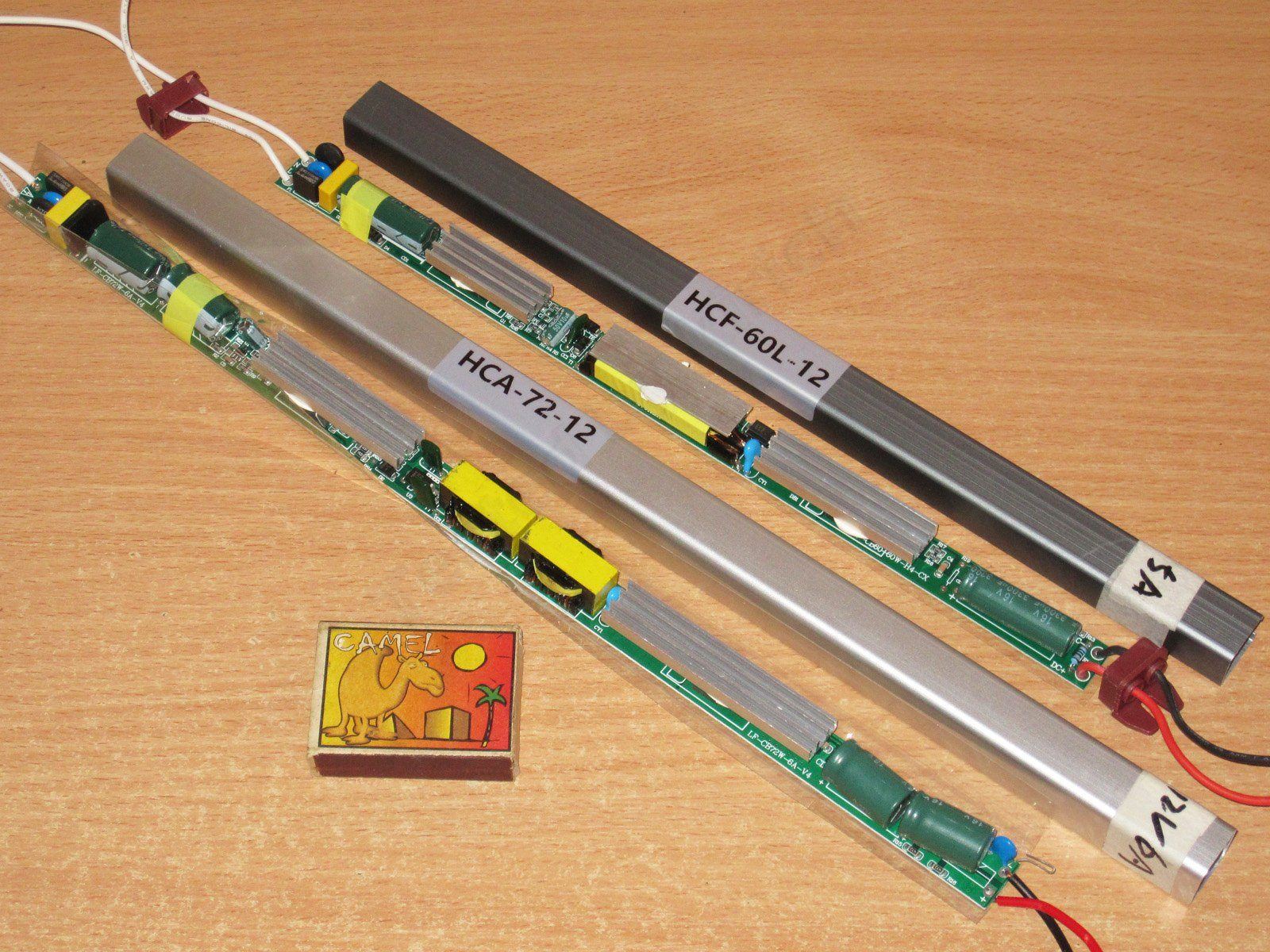
Since these models have little in common, this part of the review is split into two sections, one for each power supply. Naturally, I'll start with the 60 W version.
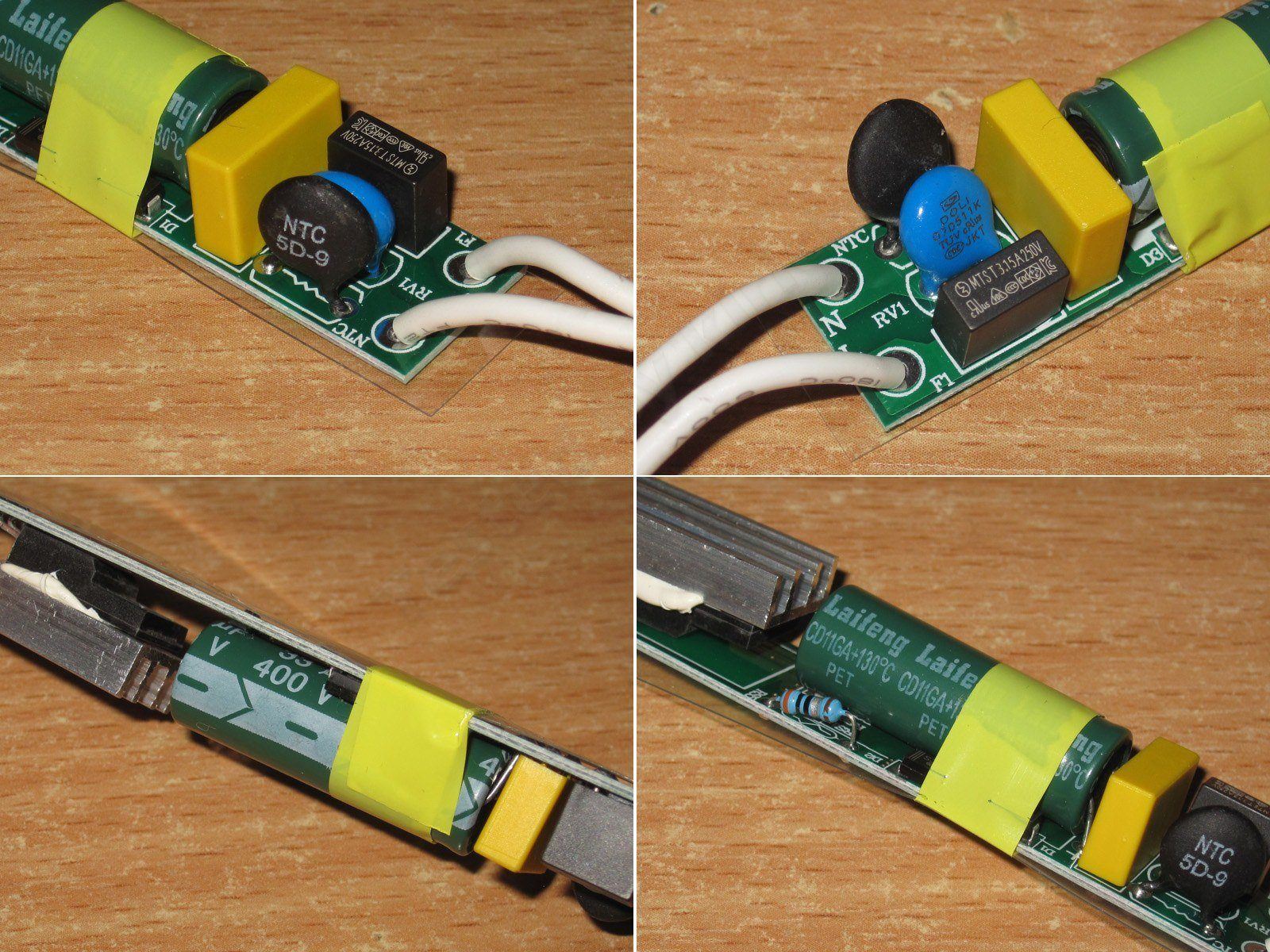
The input section is the same as in the previous HCF models: a thermistor, a varistor, and a proper fuse.
There's one capacitor, rated at 33 µF, and its temperature rating is also up to 130°C.
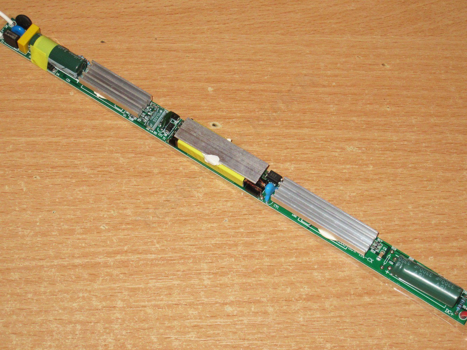
1. PWM controller 30509, the same as in the 36 and 48 W versions. I expect the interference issues to be the same, too.
2. There's only one transformer, but it's quite long, and they've attached a heatsink to it. I'm not sure how effective that is; to me, it just increases thermal inertia, and that's about it.
3. They've glued a really long heatsink to the output rectifier assembly. But judging by the gaps and the thickness of the adhesive layer I've seen on other models, it's unlikely to be as effective as it could be if it were attached properly—or, better yet, screwed down with thermal paste.
4. The output capacitor is 3300 µF, rated for 130°C.
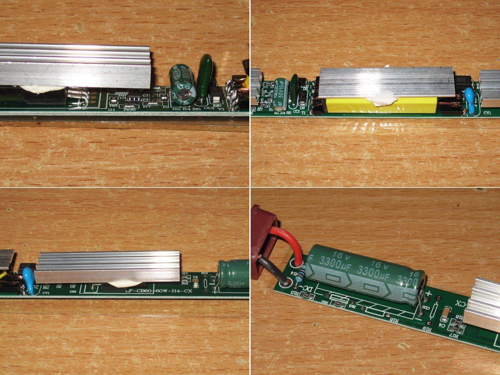
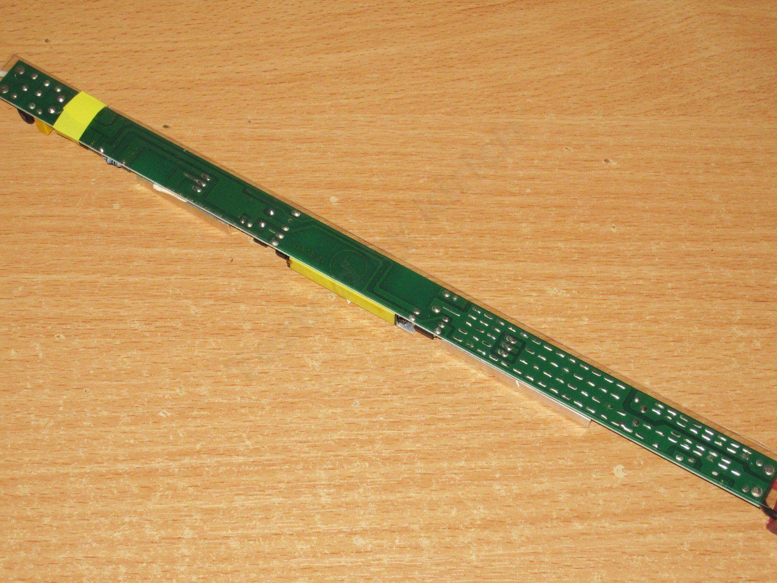
The board layout is similar to the 36 and 48 W HCF models, with the same shortcomings; the board itself is simply longer. The insulation is also only on the underside of the board. Given that the traces run right along the edge, this is quite dangerous—use only in enclosed housings.
Here's a closer photo of the problem area. I think the issue is clear: the "hot" lead of the Y capacitor is too close to the output-side copper pour. With a slight change to the PCB layout, it can be made noticeably safer, though still not perfect.
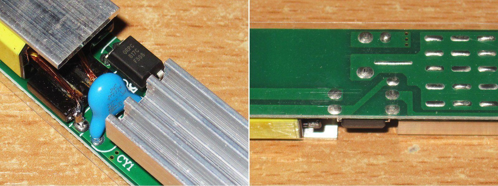
As before, I should point out that the input capacitor is a bit small for 60 W, especially with a lower input voltage.
No complaints about the output capacitor. It could be larger, but this is probably fine.
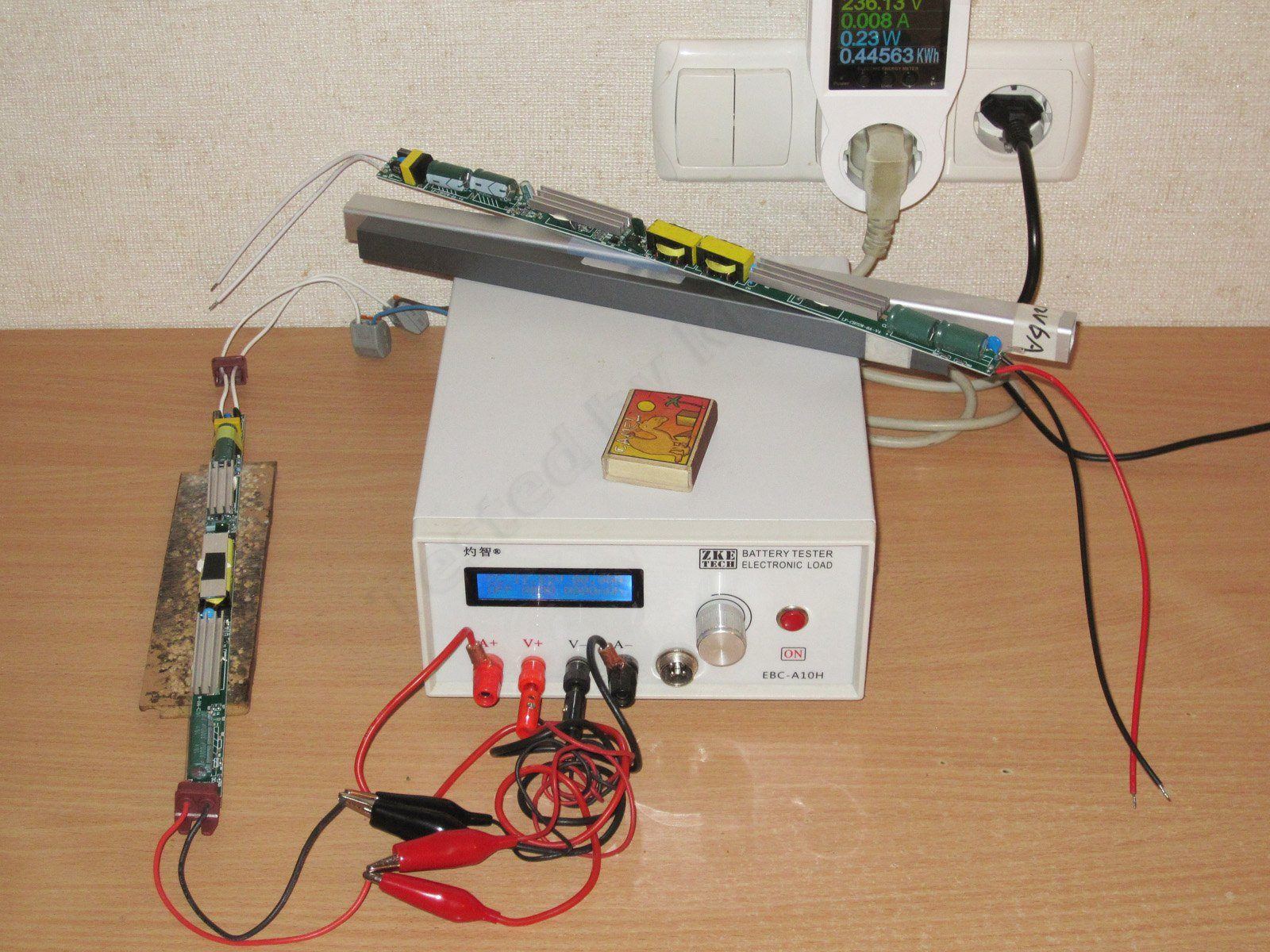
One more photo from the testing process. Here I wanted to show how little power these power supplies draw with no load: around 0.15-0.3 W. I remember when we used to be proud if a power supply drew about 1 W; now Chinese models draw three to five times less.
The protection trips at around 5.6 A and is almost unaffected by heating. Voltage regulation is quite good.
You can also see here that even with USB galvanic isolation, communication still gets stuck.
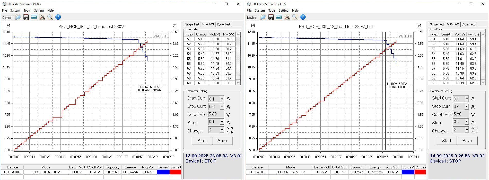
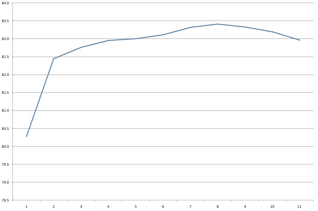
Typical efficiency, around 83-83.5%. The horizontal scale is in 0.5 A increments.
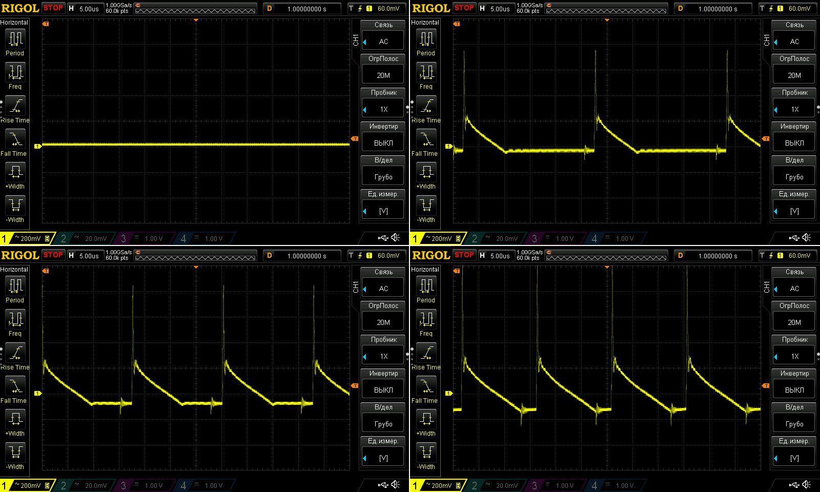
Ripple, as usual, with no load and at approximately 33%, 66%, and 100% load.
At high frequencies, everything is typical: around 400 mV at maximum current. Not great, but acceptable for undemanding loads.
I wasn't too happy with the low-frequency results. I wouldn't call them critical, just ugly: the 100 Hz component is quite noticeable.
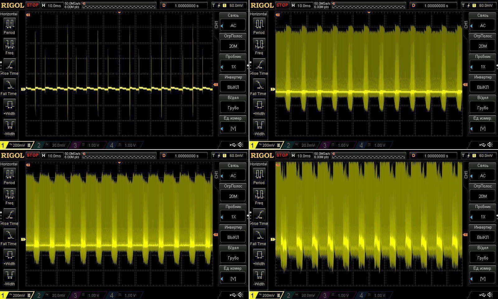
And, just like the 36 W and 48 W versions, there's a resonance that is most likely causing interference over the air.
The load test was carried out in three stages, at 3, 4, and 4.5 A. I didn't try the claimed 5 A, because the power supply was already struggling at 4.5 A.
Voltage varies only slightly with temperature, by around 50 mV, and by about 80 mV across the full load-current range. That's fine.
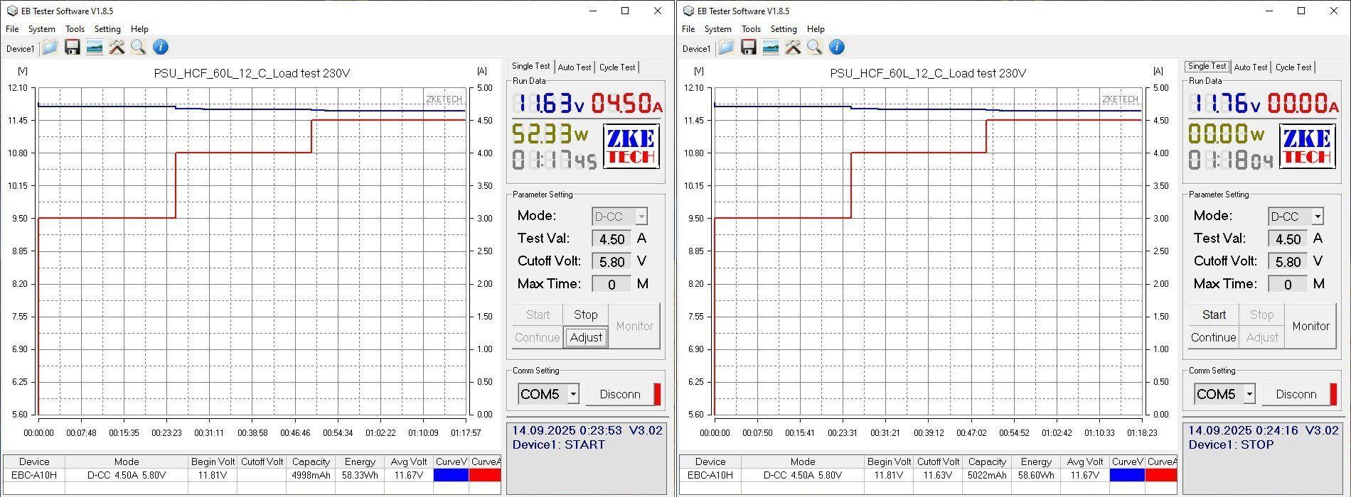
Now for the temperatures.
At 4.5 A, I measured around 100°C on the transformer, 62°C on the transistor, and 105°C on the diode assembly.
In principle, the current could be raised to 5 A, but in my opinion that's too much for this unit. The actual continuous output current in the case should be no more than 4 A.
Now for the HCA-72 model.
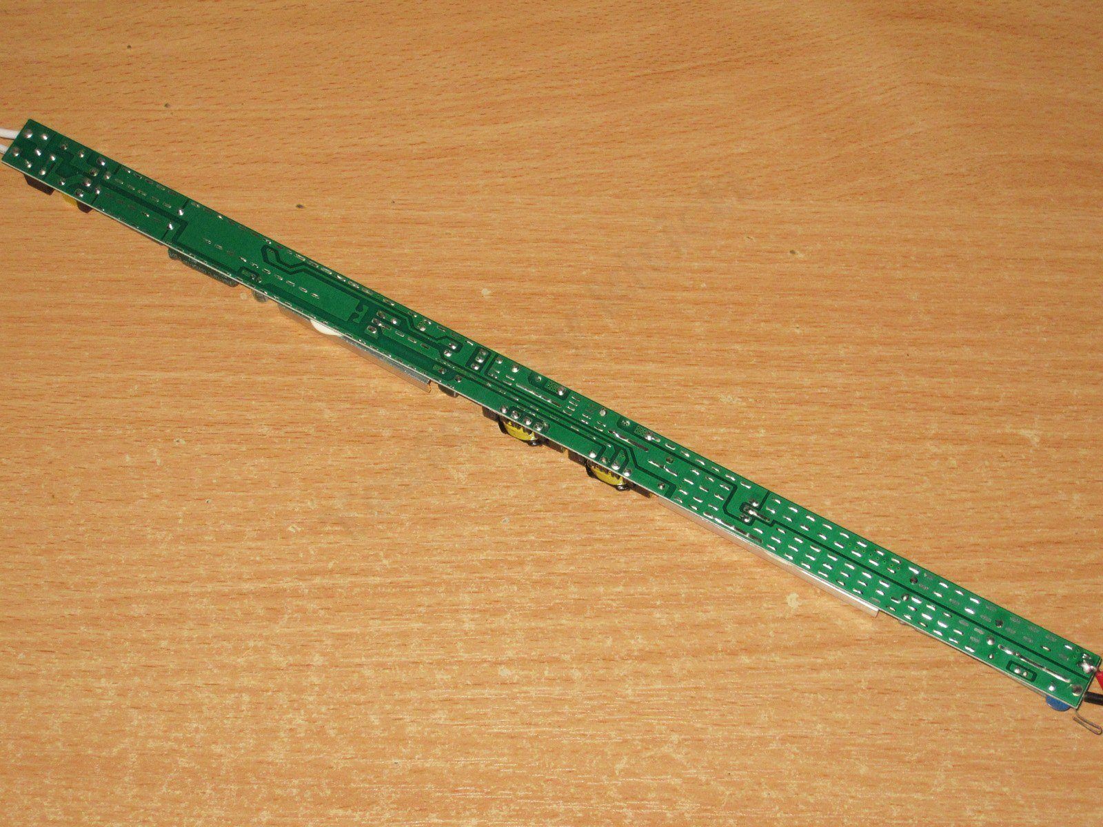
It was quite a challenge to fit this thing into the frame—it’s that long. As with the other models in this case, insulation is provided by a plastic barrier covering about 3/4
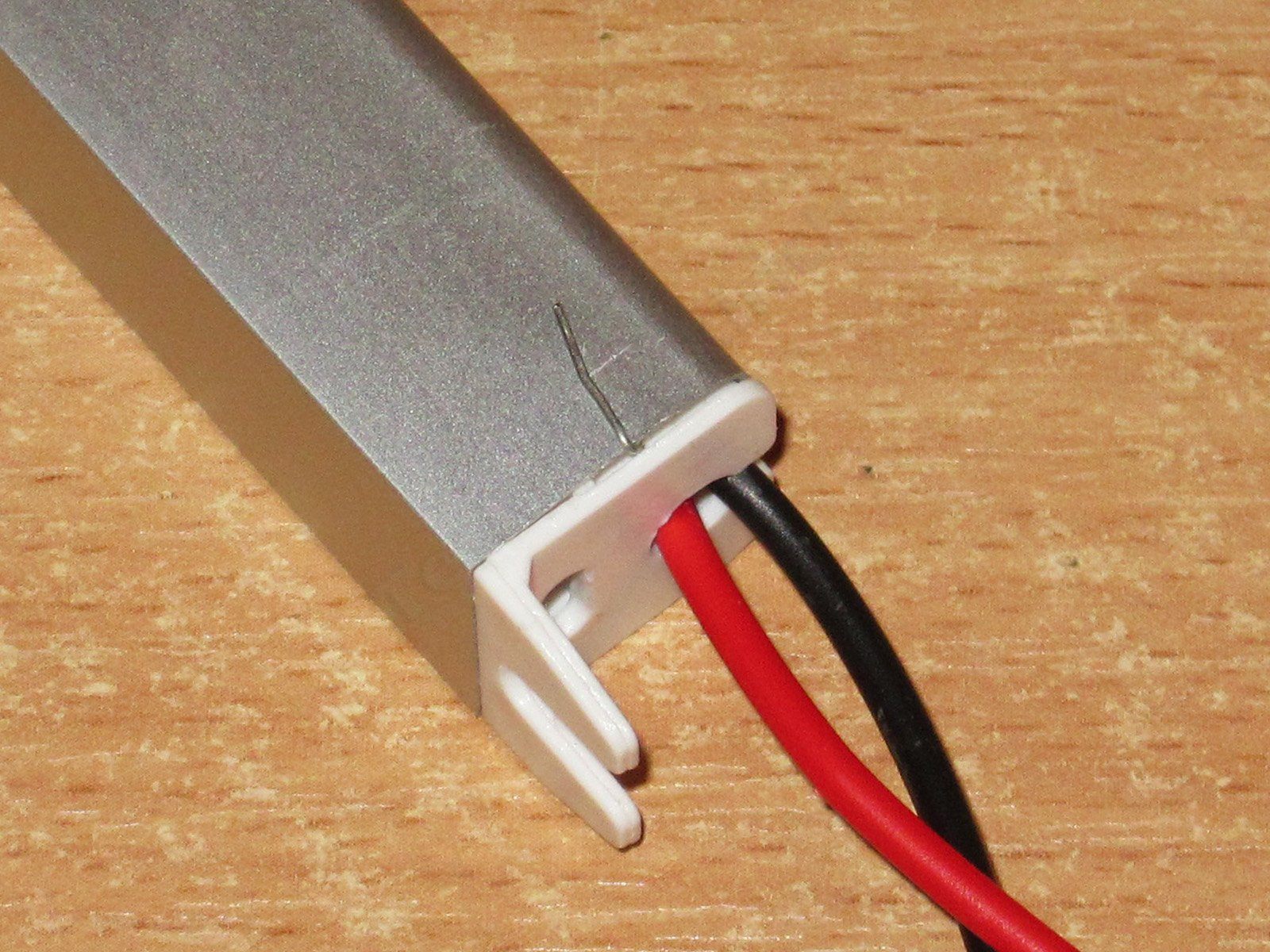
These models have a very unusual way of grounding the case: a bent capacitor lead sticks out. In my opinion, it's a poor design. First, it can easily break off; second, it's even easier to catch yourself on it and get hurt.
Surprisingly, the input section here is very similar to the HCF series models: it has a fuse, thermistor, and varistor.
The bridge rectifier is larger, there are two 22 µF, 130°C capacitors, and the transistor has a relatively large heatsink. But the PWM controller is a 30513, as in the other HCA series models, not the HCF models that spewed interference.
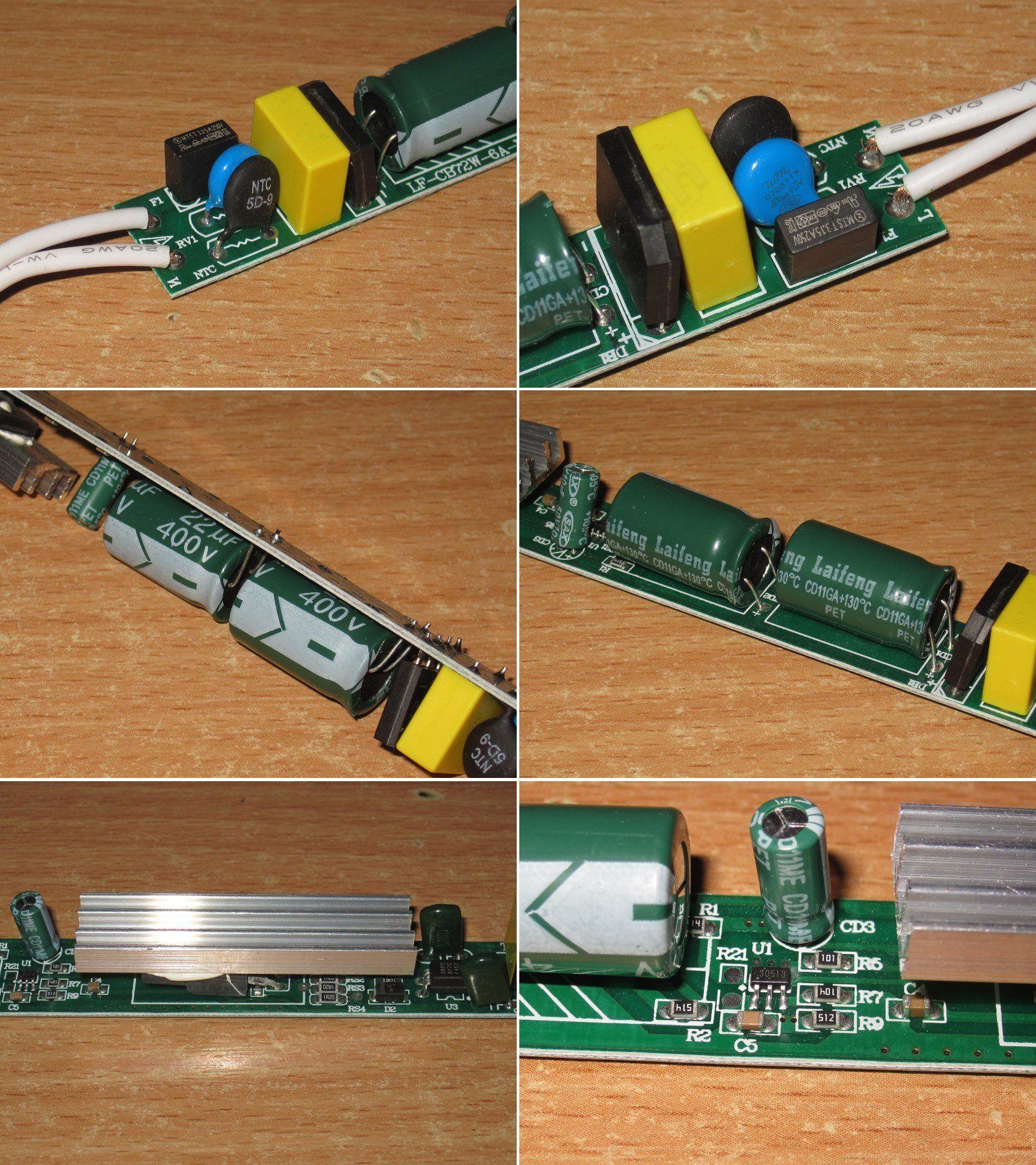
Two conventional transformers; no complaints here. This worked fine last time.
But they left the optocoupler on the hot side. Not good :(
On the output side, there are two 2200 µF, 130°C capacitors. That's fine here.
There's no point commenting here; I've already described everything about this board. Safety is very poor.
A closer look at the optocoupler section—a good example of how not to do it.
Surprisingly, the input capacitors' capacitance matches the stated value exactly, while the output capacitors are even slightly above spec. That's fine here.
But even 44 µF is a bit small for 72 W.
The protection trips at around 6 A, just barely above the claimed maximum. In a way, that's good for safety.
The current is practically unaffected by the power supply's temperature.
Voltage regulation is reasonably good. The actual variation at the terminals was around 70 mV. As the current rises to 6 A, the voltage immediately starts dropping by 0.3 V.

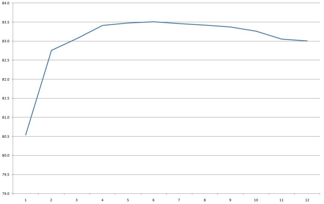
Efficiency is 83-83.5%—nothing new, all quite typical. The horizontal scale is in 0.5 A increments
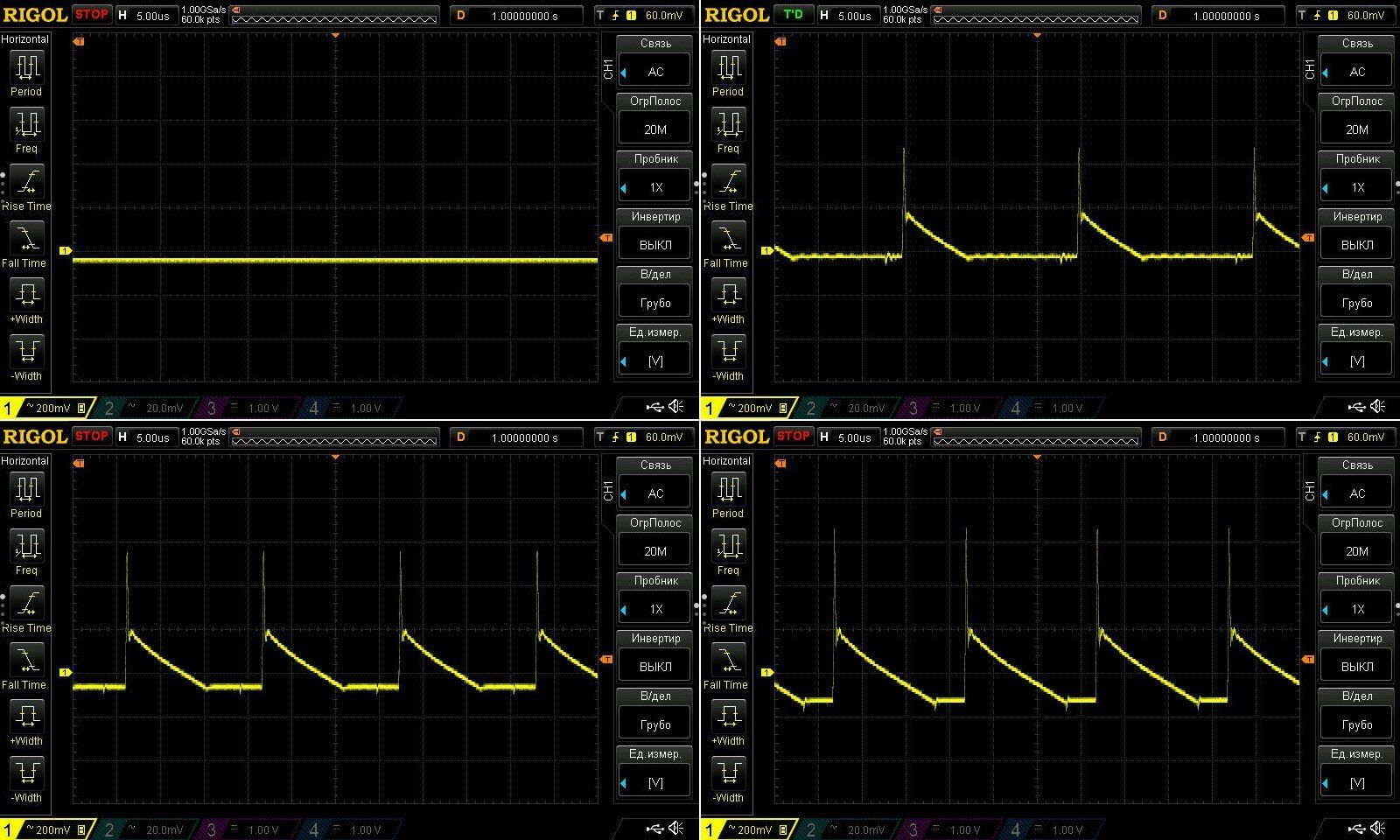
Ripple with no load and at currents of 2, 4, and 6 A.
Basically, it's acceptable: even at maximum load it's around 370–380 mV, about 3%. At 4 A it's perfectly fine, around 240 mV, which is to be expected for this class of power supply.
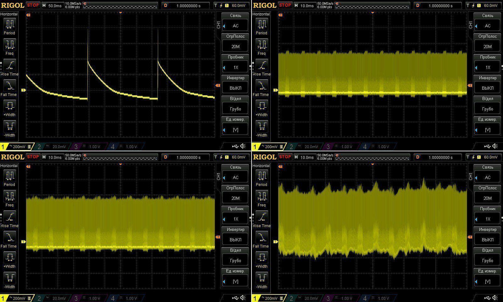
At low frequency, you can see the characteristic ripple with no load. I'm now inclined to think this is a characteristic of the PWM controller used, since we've seen this before.
There's almost no 100 Hz ripple, and the last screenshot is more likely showing the overload protection starting to kick in.
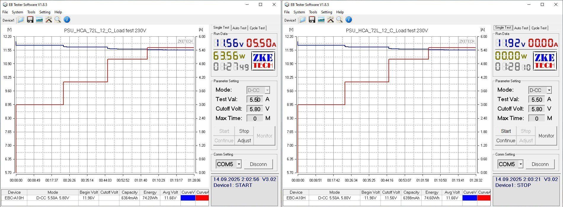
The temperature test was run at currents of 3, 4, 5, and 5.5 A. As I mentioned, the voltage doesn't vary much with temperature. It does vary with load, but that's mostly due to voltage drop in the wires.
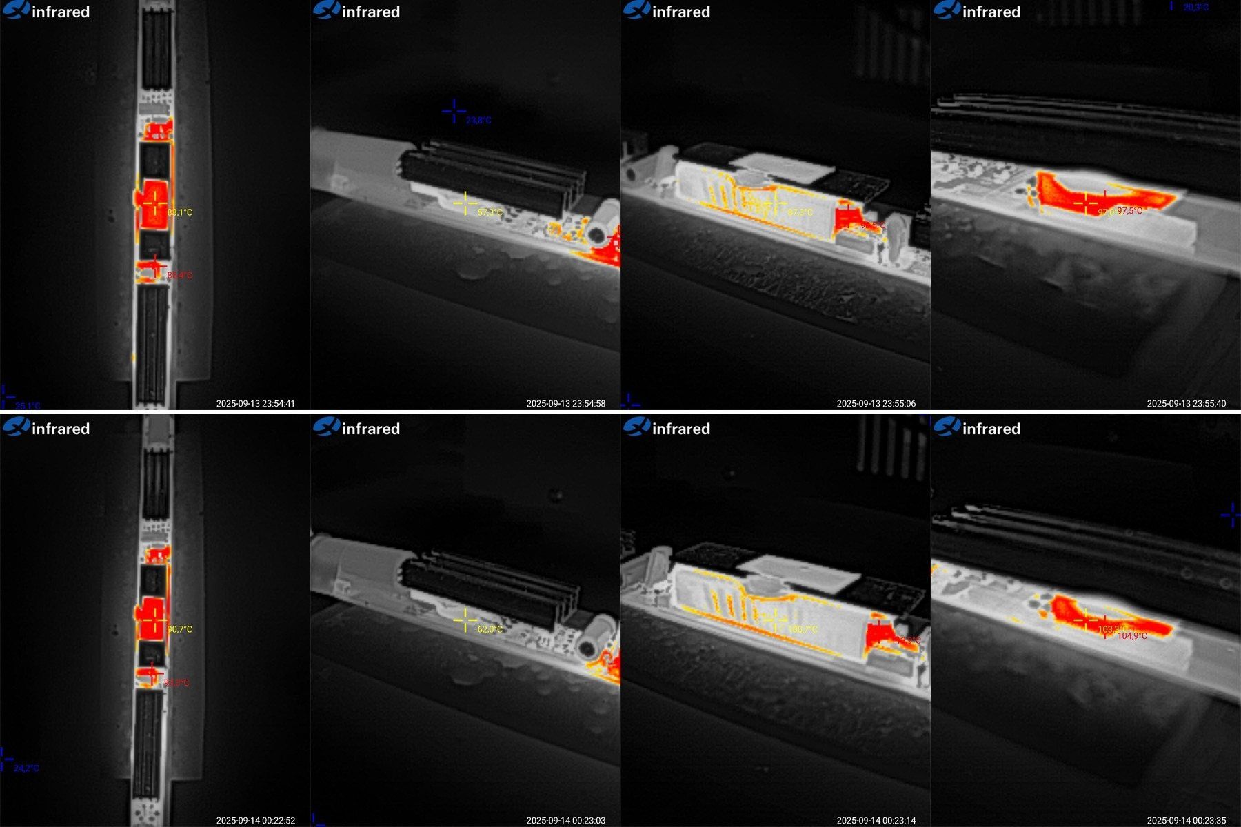
And of course, the temperatures. These photos were taken at load currents of 5 and 5.5 A.
At 5 A: the first transformer is at 76°C, excellent; the second is at 86°C, higher but still fine; the transistor is at 53°C, excellent; the diode assembly is at 102°C, a bit high.
At 5.5 A: the first transformer is at 83°C, excellent; the second is at 94°C, a bit high but quite acceptable; the transistor is at 56°C, excellent; the diode assembly is at 111°C, too high.
This isn't the first time I've noticed that the diode assembly is usually the first thing to overheat, followed by the transformer, while the high-voltage transistor usually has plenty of headroom. I don't know why they didn't put two diode assemblies in parallel and use a larger heatsink, but it would have worked a little better.
So, in this enclosure, the continuous current should be no more than 5 A.
And now the fifth pair: HCA-100 and HCA-100L power supplies. Both are rated at 100 W, with a current of 8.3 A.
Essentially, these are the same power supply. The difference is in the construction: the second one is marketed as sealed, although it isn't potted. The edges around the end caps are simply coated, and the caps themselves are metal. So the sealing here isn't great; it's more that water is less likely to get inside right away.
Dimensions:
HCA-100 - 244/265 mm, cross-section 25.5 × 16.5 mm
HCA-100L - 242/264 mm, cross-section 32 × 17 mm
The cables are like our PVS wire, reasonably flexible.
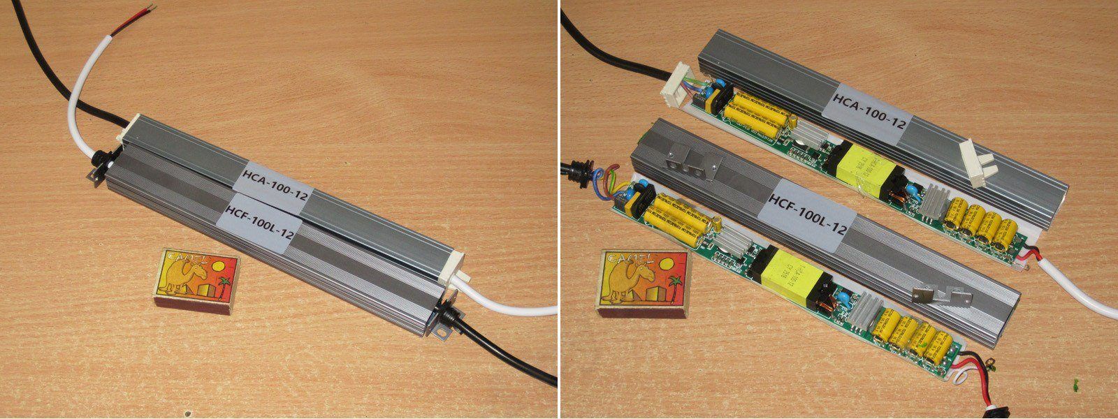
These models have insulation made of a denser plastic, reminiscent of the shades on cheap light fixtures, but it covers less than half the perimeter, forming more of an improvised trough.
And yes, you can clearly see here that these are two absolutely identical circuit boards.
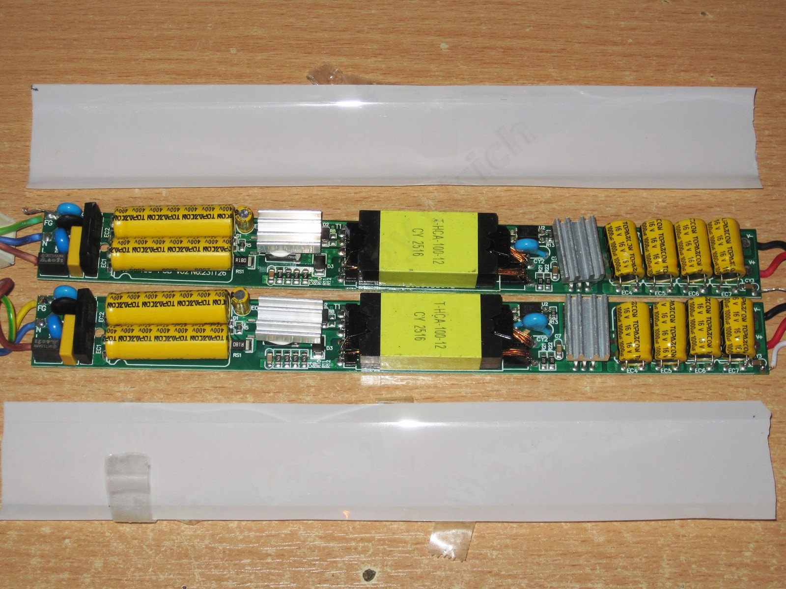
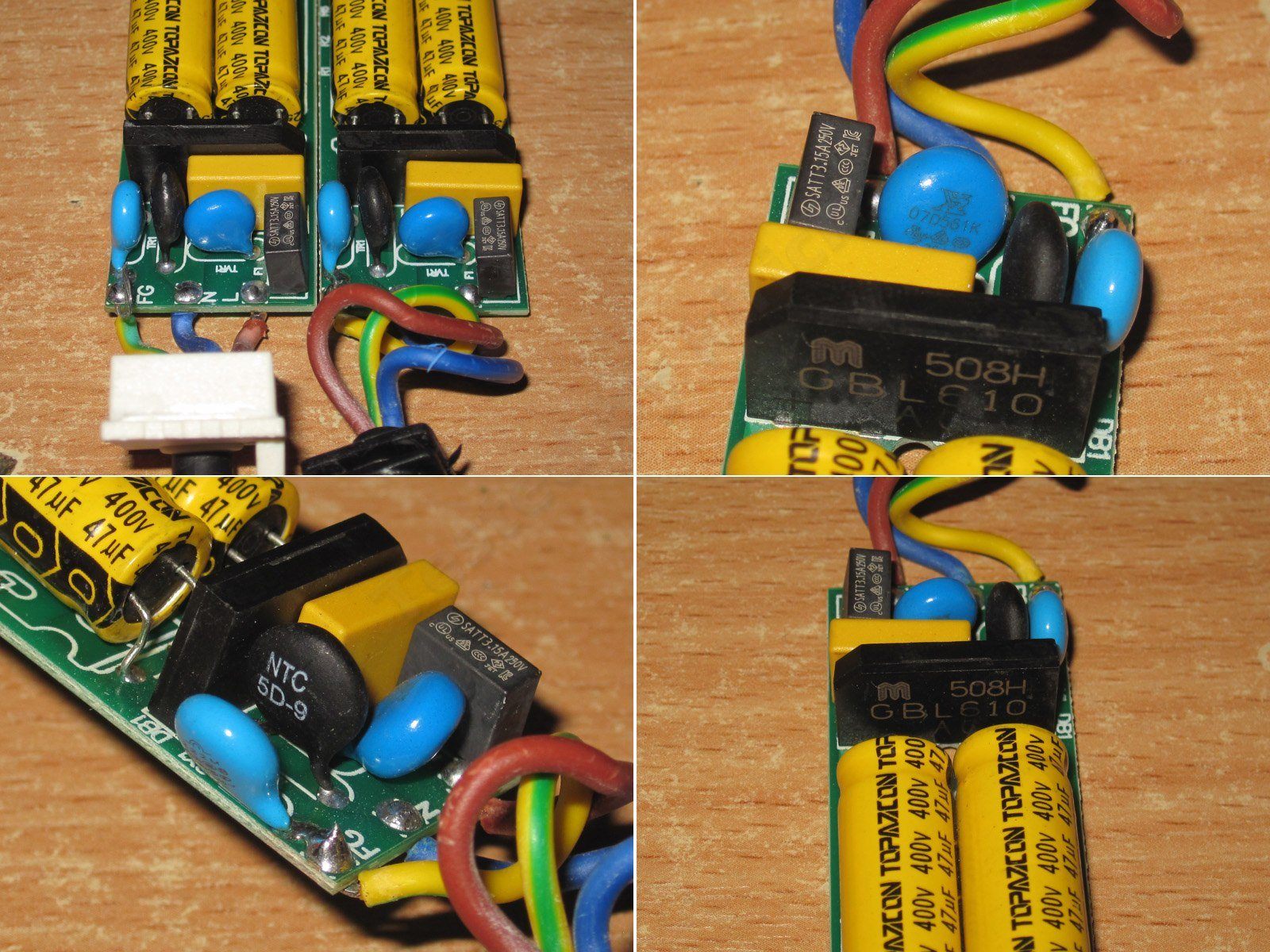
There's no EMI filter inductor, but otherwise everything looks fine: thermistor, varistor, fuse, and X capacitor.
The varistor is rated for a 560 V peak voltage, so it protects against surges in the mains, which most often occur during thunderstorms.
The input capacitors are 47 µF each, almost 100 µF total, which is quite enough for this power rating and our mains supply. But interestingly, all the previous units had 130°C capacitors, while this one uses a different manufacturer and 105°C capacitors.
Even the shunts are identical, rated at 180 mΩ, as are the transformers.
There are four 1000 µF capacitors in parallel on the output. Although the total capacitance is only 4000 µF, I'm glad they used four rather than one large capacitor; this usually has a positive effect on ripple and service life.
The very small output heatsink immediately caught my attention, and naturally I suspected a synchronous rectifier. And yes, that's exactly what it is. I actually have some just like these at home; I bought them before the war for experiments. I should at least try to find them.
The output is also connected to the case through a capacitor, so the case can act as a shield against outgoing interference. Here, though, the connection is made with a stranded wire.
The only thing is, according to the datasheet, although these can handle high current, they're intended for 12 V switching power supplies with currents up to 5.5 A. The highest-current version of this kind of "diode" is rated for power supplies up to 6.5 A, so it's overloaded here.
The underside of the board is clean and tidy. The safety features are also well thought out: not only is there plenty of clearance, but there’s also a slot. It feels like this board was laid out by a completely different person—someone who’s clearly an engineer. The output has a bank of small capacitors rather than one large one, and there’s a synchronous rectifier.
Overall, it’s already clear that this is a power supply in a different league.
The actual input capacitance is 85 µF, somewhat short of the claimed 94 µF, but still quite sufficient. The output capacitance is noticeably higher than specified; it could have been higher still, but it’s enough as is.
Let’s start by testing the HCF-100 model, which has a slightly smaller case.
The overcurrent protection kicks in at about 9 A, which is generally fine for the claimed 8.3 A. The protection reduces the voltage rather than shutting the output off completely. There’s no temperature dependence.
Efficiency reaches 89%. This is a good example of how much difference a single component can make: a synchronous rectifier instead of a regular diode.
Yes, they cost more, but folks, they’re so much better.
The horizontal scale is 0.5 A per division.
Ripple was checked with no load and at currents of 3, 6, and 9 A.
At 9 A, the main ripple component had an amplitude of about 200 mV. I wouldn’t call that low, but it’s perfectly acceptable, although given the design I expected less.
At 100 Hz, everything looked very good up to 9 A. At that point some kind of noise started creeping in, but for the most part I have no complaints about this power supply—especially considering that this was at an overcurrent level.
The long-duration test was run at 3, 4.5, 6, and 7.5 A. I have no complaints about voltage stability.
In fact, I’d like to point out how exceptionally stable the output voltage is: it didn’t change by even 0.01 V across the entire range, from no load to 9 A.
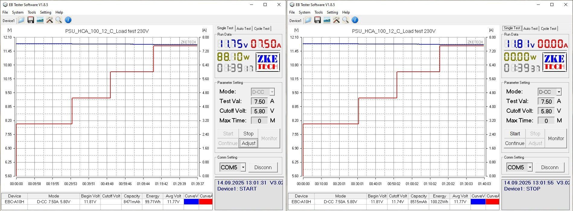
The test results were somewhat predictable, but I’ll go into more detail. At 6 A, everything is excellent, so I’ll move on to 7.5 A.
Transformer: 79 °C, excellent. Transistor: 85 °C, good. Output “diode”: 110 °C, too hot.
I mentioned above that the synchronous rectifier used here is intended for 12 V, 5.5 A power supplies. It works perfectly well at 6 A, but at 7.5 A it’s clearly being pushed to its limit. So, in my view, this is a perfectly good power supply for continuous operation at 6–6.5 A, provided it’s installed in a case.
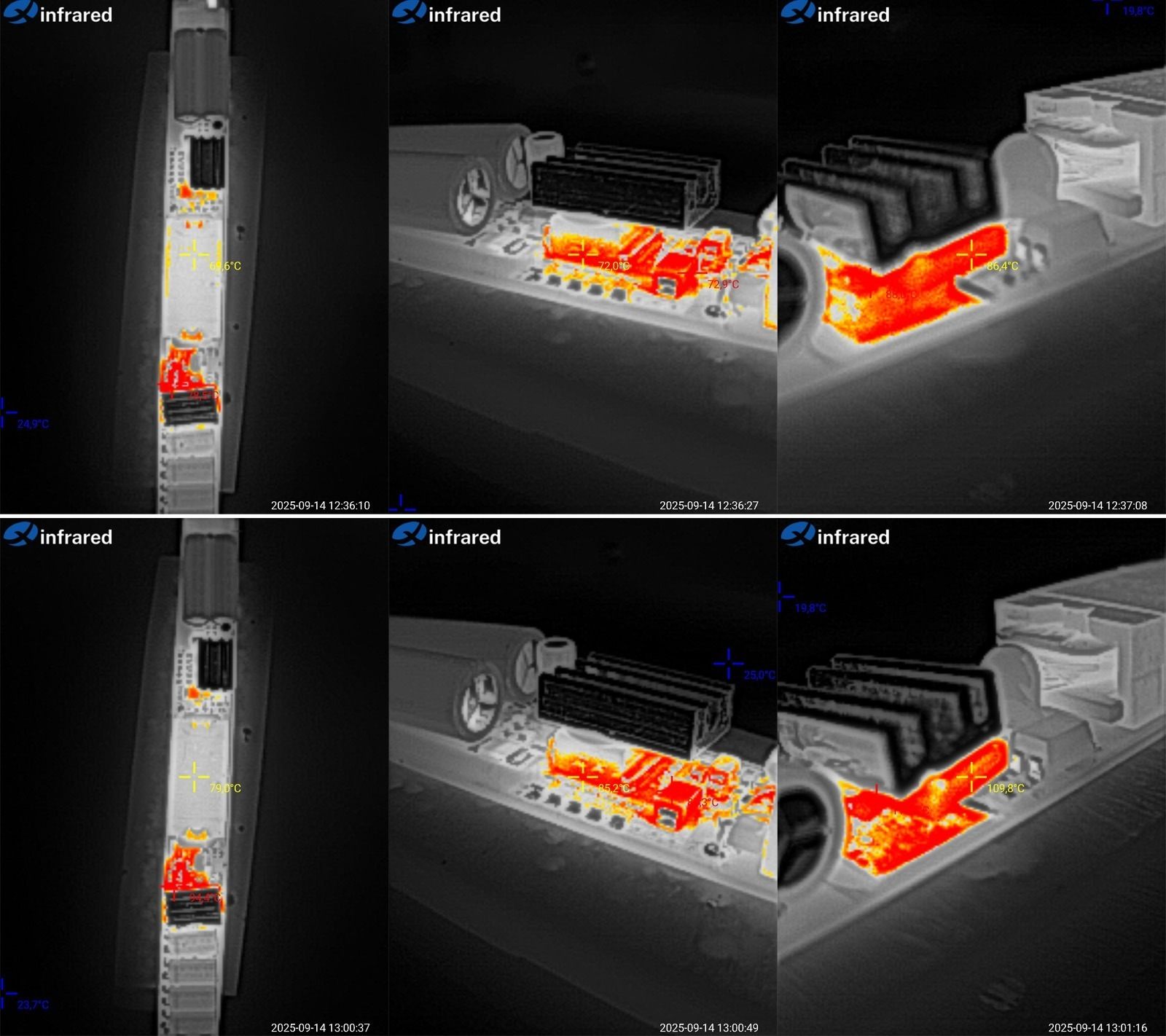
HCF-100L model.
Although it uses the same board, since this power supply has already landed in my hands, I’ll test it too.
But here’s something interesting: this unit’s overcurrent protection trips at 8.3 A, compared with 9 A for the previous one. That’s too large a difference to put down to measurement error, especially since the shunts in these units are identical. By the way, 8.3 A is actually the claimed maximum for a 100 W, 12 V power supply.
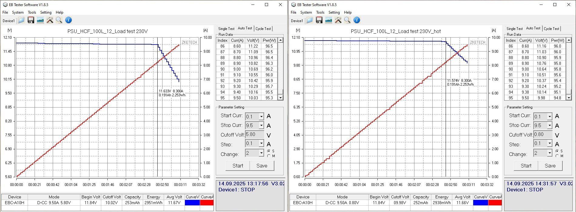
Efficiency is identical, which is what you’d expect. It would be strange if there were differences here too.
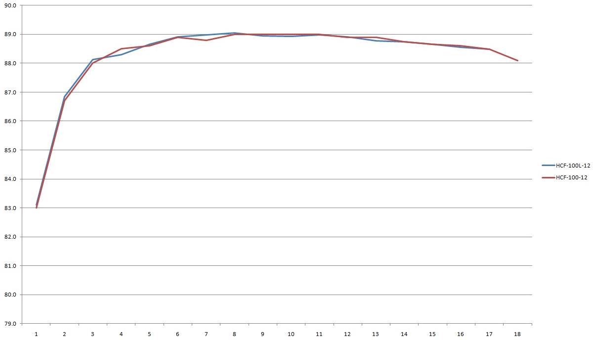
The ripple is essentially the same, although this unit was tested with no load and at 3, 6, and 8 A, rather than 9 A as with the previous one.
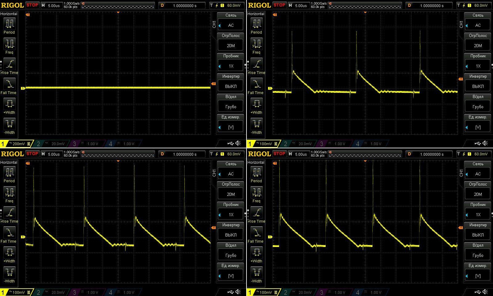
You can see here that at 100 Hz and 8 A, everything is perfectly fine. The previous unit was tested at 9 A, and its protection trips at 9 A. This one was tested at 8 A, with protection set at 8.3 A.
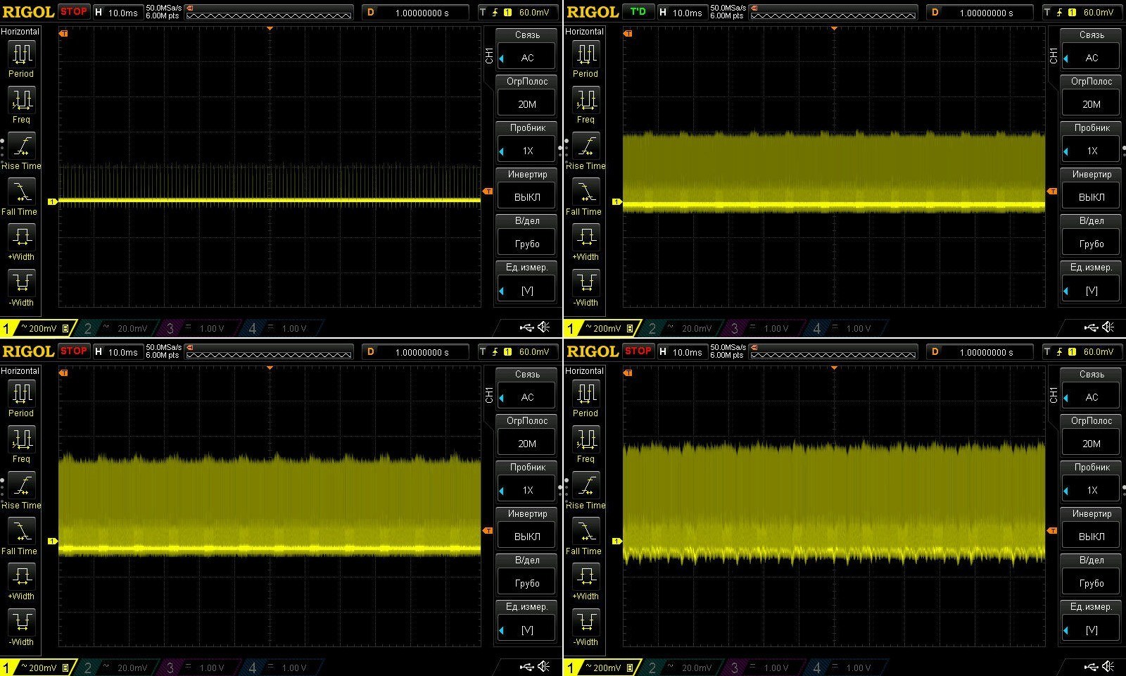
Honestly, I couldn’t be bothered to go through all the thermal soak stages here, so I changed the procedure a little: I loaded it straight to 6 A, then to 7.5 A. The total test time was about an hour.
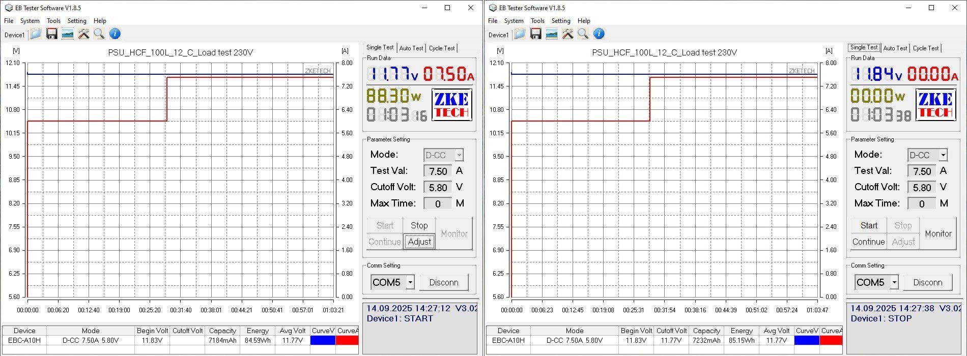
At 7.5 A, the transformer was at 81 °C, the transistor at 88 °C, and the output rectifier at 112 °C. I got roughly the same results with the previous unit.
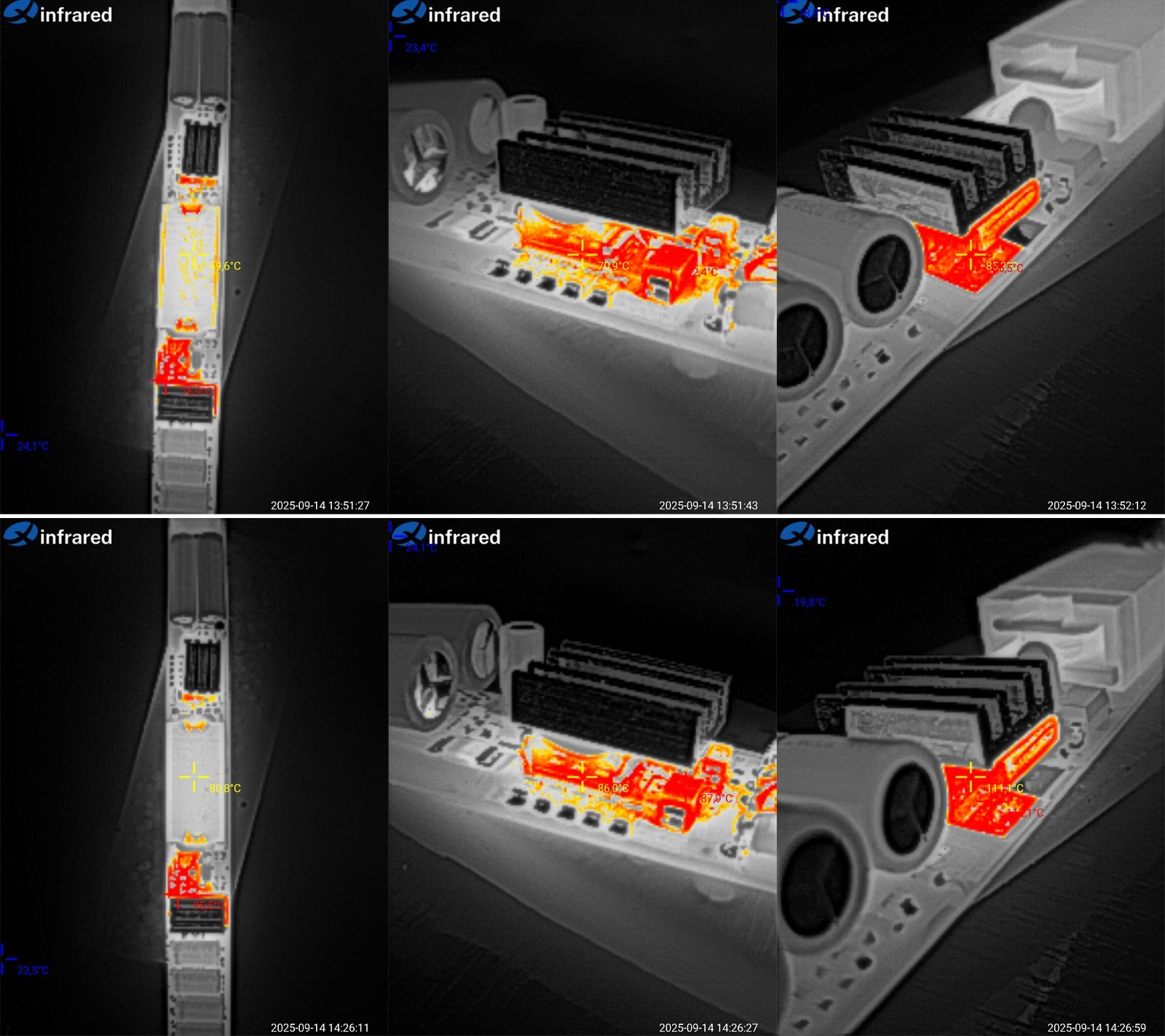
Later, I decided to take a photo of what it all looked like after the tests were over :)
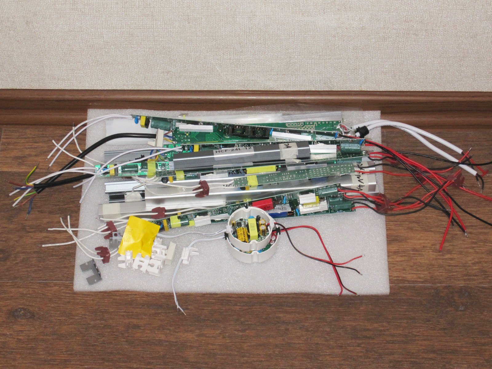
Conclusions.
First, a point that applies to almost all the models, except the 100 W versions: safety. In fact, all 8 models have some kind of electrical safety issue, some more serious than others. That’s why I want to stress that these power supplies should only be used where neither the power supply itself nor any of its electrical circuits—on either the input or output side—can be accessed. I also recommend grounding the power supply output and observing the correct input polarity: always connect the live wire to the input terminal with the fuse.
The 100 W models have almost no safety issues. The only thing that could happen is the heatsink coming loose from the transistor. By the way, these are the only power supplies in the test whose input cable not only has the live wire clearly marked, but also includes a ground wire. That’s exactly why I decided that an engineer must have designed it after all, while the 100 W rating came from a marketing person.
I should also mention the rather odd case design on some models: steel, with a wide slot. I’ve never seen anything like it.
I almost forgot: all models except the 100 W ones use capacitors rated for an upper temperature limit of 130°C. That’s certainly impressive, but their sizes are also rather odd: capacitors with the same capacitance differ in size, while ones with very different capacitance are almost the same size. That’s why I have doubts that the capacitors are really rated for 130°C.
Now, the individual models.
HCF-18L and HCF-24L. I’d call these relatively decent. At least they deliver their rated power, and they’re built around an integrated PWM controller, which also provides overtemperature protection. Ripple is acceptable, and so is stability. Setting aside the safety issue, these are pretty good little power supplies.
HCF-36L and HCH-48L. These are worse. As I mentioned, I wasn’t happy with their interference. In other words, their ripple is acceptable, but they generate a lot of RF noise, which is not good and can also interfere with devices that use microcontrollers.
The 36 W model runs at a reasonable temperature, but the 48 W model overheats. It also starts reducing its output voltage at 4 A, so if you use it, it’s best not to load it to the limit. Honestly, I didn’t like either of these models, mainly because of the interference.
HCA-48 and HCA-60. Although these models look identical on the outside, they’re very different inside. The 48 W version has overheating problems; in reality, it’s good for 36 W at most. The 60 W version does better, but it’s really closer to 50 W, and its ripple is fairly high. Both models also have a strong load-dependent output voltage, especially the 48 W version. And instead of a fuse, both power supplies have a resistor on the input. It’s probably a fusible resistor—a hybrid of a resistor and a fuse—but I much prefer the thermistor-plus-fuse arrangement.
HCF-60L. Essentially, this is almost identical to the HCF-36L and HCH-48L: the same PWM controller and the same interference. That’s why I don’t recommend it, even though its ripple and temperature performance aren’t bad. Its maximum power, however, is no more than 45–50 W.
HCA-72. This is somewhere between the HCF and HCA models shown earlier. It doesn’t have the kind of interference seen in the HCF-60L. There is some ripple, but it’s tolerable. It runs fairly hot, so in reality this is more of a 60 W power supply than a 72 W one. But the biggest complaint is its safety; everything else is tolerable.
HCF-100 and HCF-100L. As I wrote, these are the same power supply, although I was a little surprised by the difference in their overcurrent protection thresholds. Overall, they’re quite good in almost every respect. My only real complaint is the rated power: in reality, these are more like 70–80 W power supplies; anything higher is just a marketing person’s dream. I liked both the circuit design and the components, as well as the low ripple, excellent output voltage stability, and fairly high efficiency. Overall, I can recommend them, as long as you keep the actual power rating above in mind.
So, in brief:
HCF-18L and HCF-24L are decent, but have poor electrical safety.
HCF-36L, HCH-48L and HCF-60L. I don’t recommend them, mainly because of the combination of poor safety and very high interference levels, even though they passed some of the tests reasonably well—not perfectly, but acceptably.
HCA-48 and HCA-60. It’s a mixed bag. Yes, they have safety issues, but they should be usable at reduced power. There are some concerns about overheating, though; overall, they feel a bit rough around the edges.
HCA-72. If you can overlook the poor safety and reduce the load from 72 W to 55–60 W, it’s actually quite decent.
HCF-100 and HCF-100L. These were my favorites. They don’t have many drawbacks, really: one is that the heatsink could come loose and short something inside; the other is that the power rating is overstated. In reality, these power supplies are good for 70–80 W at most. Still, they’re very good.
That’s probably all for today. This review turned out rather long and a bit... exhausting, but I hope it’ll be useful. And of course, thanks to Vitaly for providing these samples of Chinese industry for testing :)
This page was found when searching for:
hcf блок питания
hcf блок питания
This model is included in the summary table: Comparison of power supplies: ripple, efficiency, and temperature rise
The figures from this review are in the measurement database: Power supplies
Calculate manuallyAll calculators
Discounted products
You may be interested in



Discounted products
Support the project
All the content on the site and the advice are free, but we’d be grateful for your support of the project and the channel!
Discuss on the forumHave a question or some experience to share? Discuss the article with the author and readers: the forum is a convenient place to share schematics and photos.
Go to the forumOnly registered readers can comment. It takes a minute to sign up, and you can log in with the same account you use on the forum.
Log inRegister