
5 V power supplies: 10, 25, 40, 100, 150, and a couple of 200 W models
This turned into a quick-fire roundup: seven power supplies at the same voltage, 5 V, but with different power ratings.
These power supplies are often used to power addressable LED strips, LED displays, and similar things, but there’s nothing stopping you from using them for other purposes too.
To keep up with new posts on the blog, I recommend following me on Instagram. I’ll post notifications about new articles there and maybe write about something interesting too - link to my account
You can also follow updates and new articles on the Telegram channel - https://t.me/KirichBlog Note that the channel is open for discussions about reviews and articles, as well as just chatting. I recommend it.
There are a lot of power supplies here. I could have done seven separate reviews, of course, but since they’re all from the same manufacturer, have the same output voltage, and arrived together, I decided to cover them all at once. So this is going to be a long review.
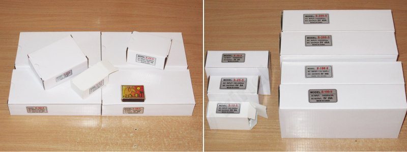
As always, I’ll go from the smallest to the largest, starting with the 10 W model. Here’s the little guy.
Case dimensions: 70 × 39 × 30 mm
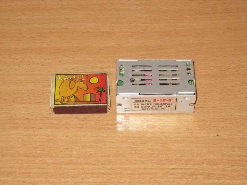
It has an output voltage adjustment and a standard terminal block. Interestingly, even this little guy has a ground terminal.
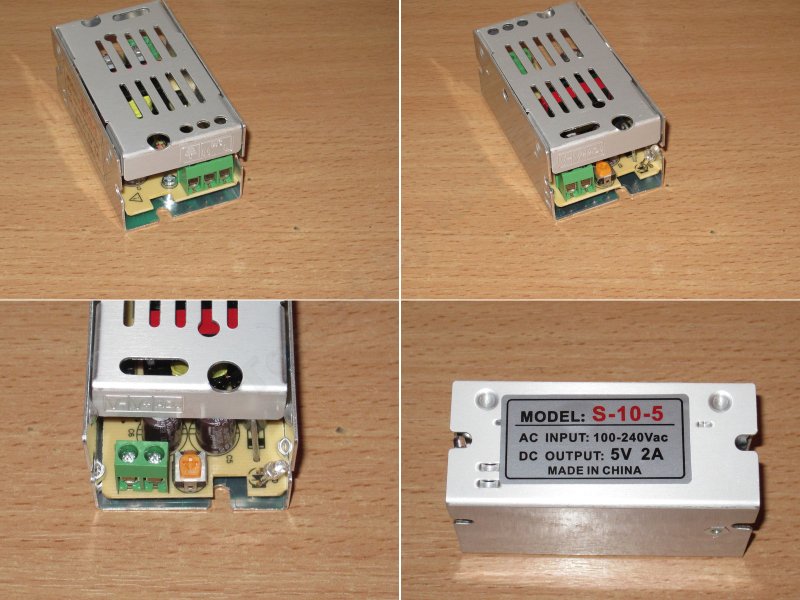
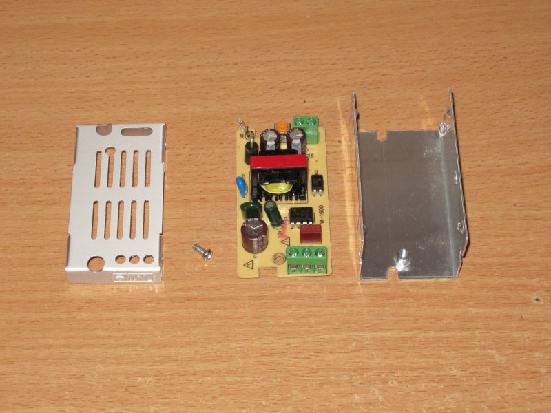
The top cover doesn’t even have any fasteners; it’s basically held in place by the case’s protrusions.
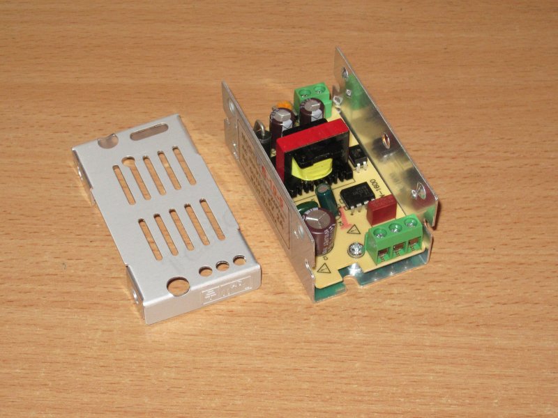
There’s no filter, just a fuse. The input capacitor is made by Aishi, but this is probably the only one of the seven power supplies with branded capacitors.
The output capacitance is 2 × 470 µF, but rated for 16 V, which is massive overkill for 5 V.
The output diode looks like a 5 A part, although diodes in this package are more often rated for 3 A. That seems a bit low for an output current of 2 A, but the tests will tell.
The power supply is built around a dedicated dk1203 PWM controller rated for 12/18 W.
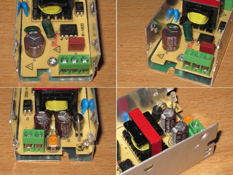
Undo one screw and you can get to the circuit board. It’s a pleasure to take apart :)
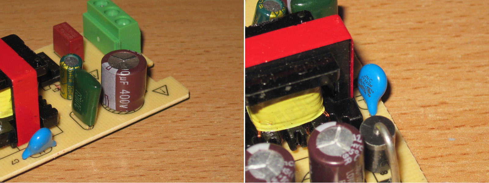
The input capacitor is 10 µF, and there’s a Y capacitor.
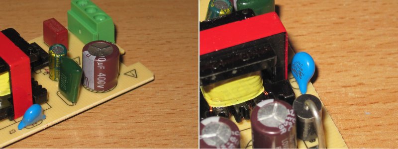
By the way, about Y capacitors. I mention them often in my reviews, and I’m very critical when unscrupulous manufacturers use ordinary high-voltage capacitors instead.
The point of a Y capacitor is that it’s safe and extremely difficult to make it fail short. Here are a few details.
What happens if you use a regular high-voltage capacitor in its place? First, even a Class Y1 capacitor must withstand impulse overvoltages of up to 8 kV, and a Y2 capacitor up to 5 kV. So if you install a regular one, often rated for just 1 kV, the chance of it breaking down is even higher.
This can lead to several problems. First, you could get an electric shock. Second, if the power supply's output side is grounded (which makes a breakdown even more likely), it could cause a short circuit and a fire.
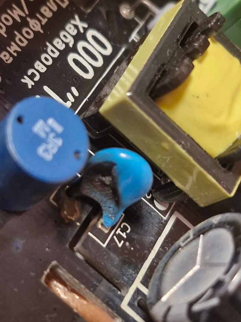
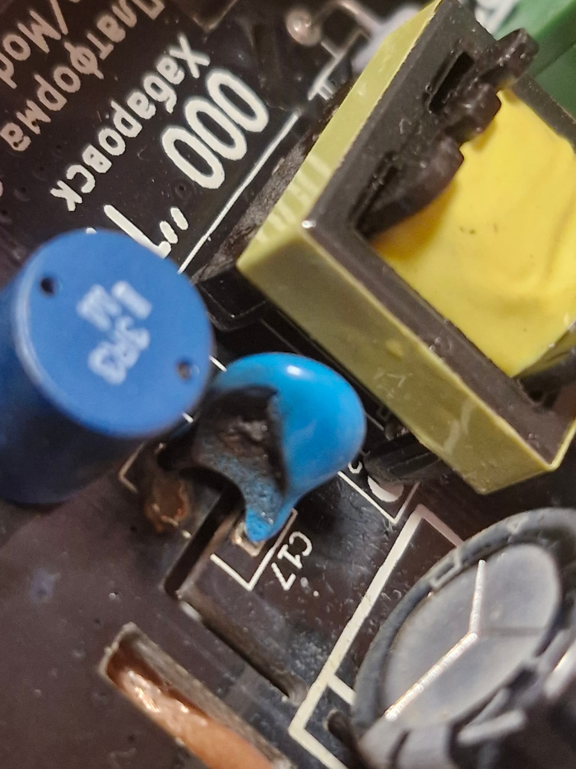
Here's a typical example of this kind of failure (photo from here). Judging by the photo, I can assume that:
1. This is a regular high-voltage capacitor. A characteristic feature of Y capacitors is that their leads are spaced noticeably farther apart and often extend beyond the body, unlike regular capacitors, whose leads are arranged as in this photo.
2. The capacitor is installed between the cold and hot sides of the power supply. The slots in the circuit board also support this conclusion.
But we can also see that the space is designed specifically for a regular capacitor; a Y-type one simply won't fit. The power supply is clearly made in Russia, and most likely designed there too. Perhaps it was designed by students, or perhaps a qualified engineer deliberately came up with this as a way to reduce the population :)
In short, I can live with the quality of the other components, overheating, under-rated power, and so on, but I absolutely do not approve of power supplies that use a regular capacitor instead of a Y-type one.
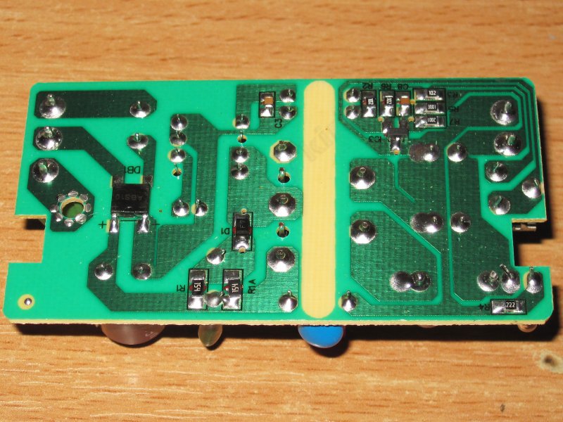
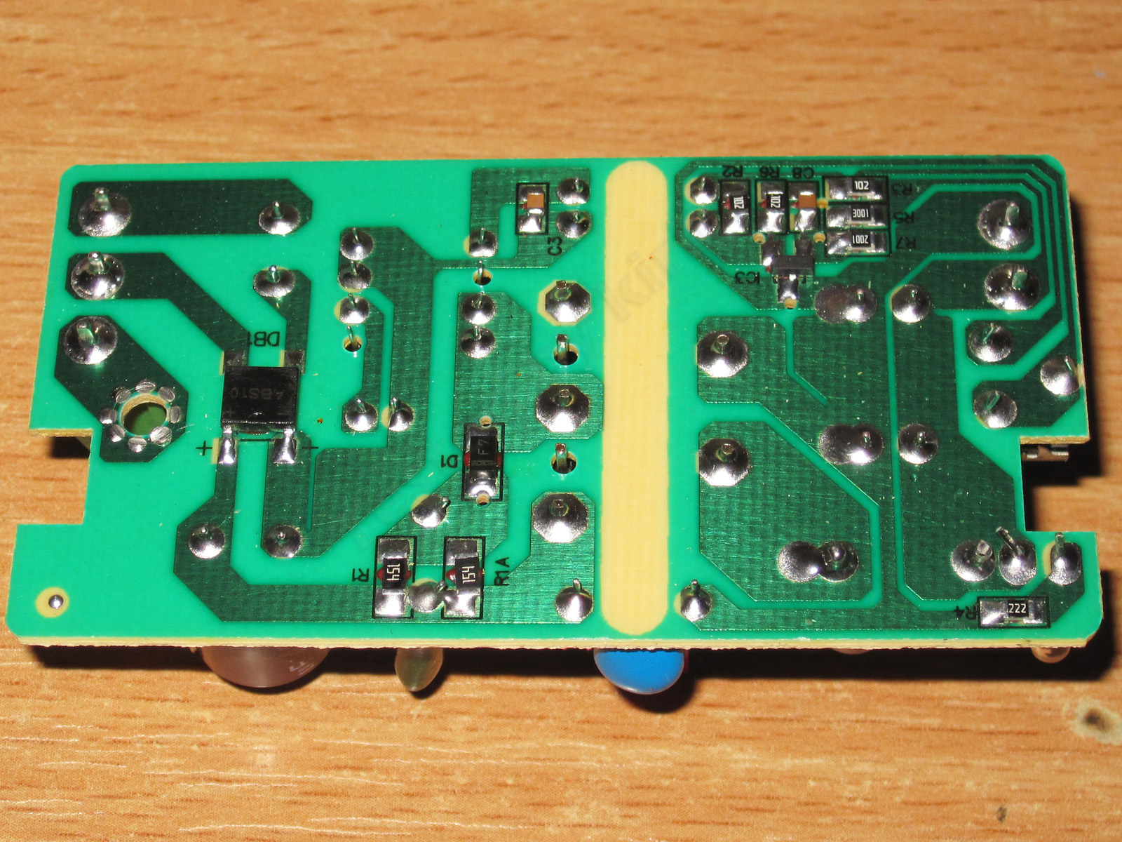
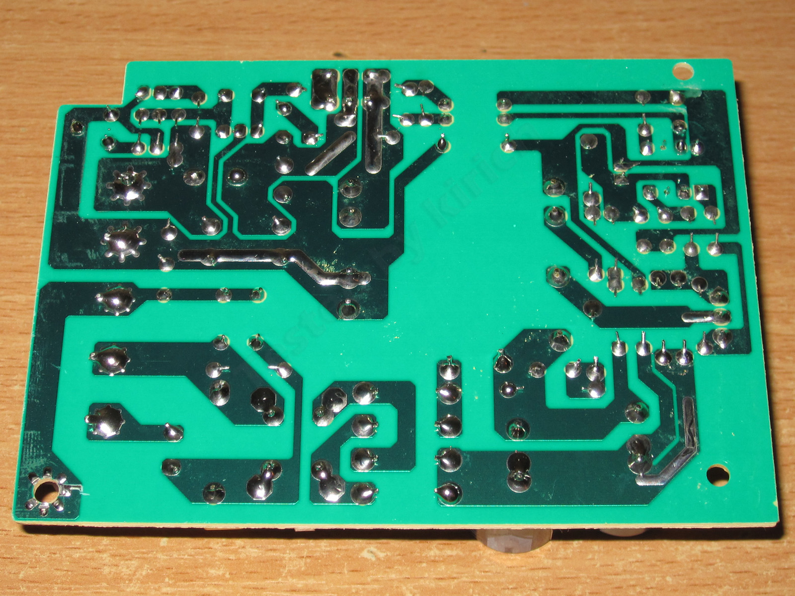
The underside of the board is clean and tidy, with adequate clearances. No complaints.
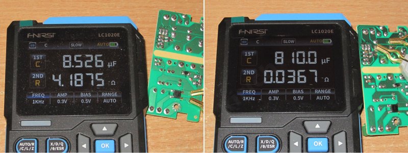
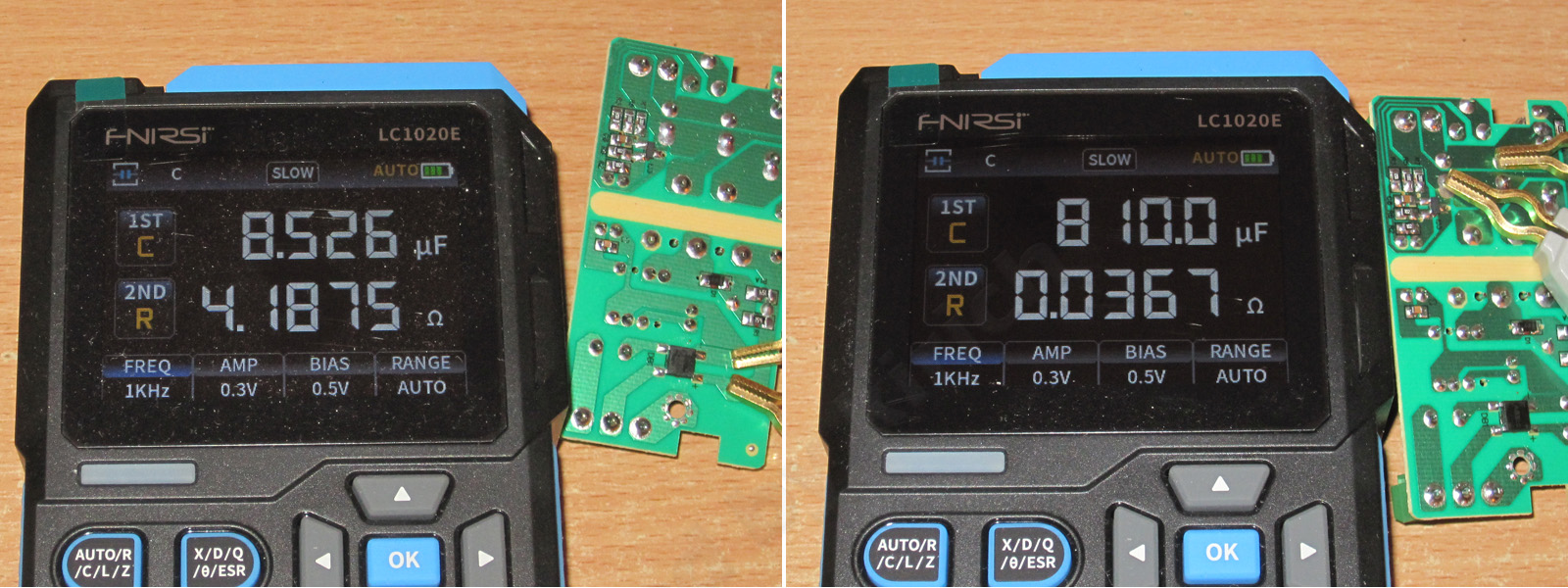
The measured capacitance is 8.5 µF for the input capacitor and 810 µF for the output capacitors, though there may be some measurement error.
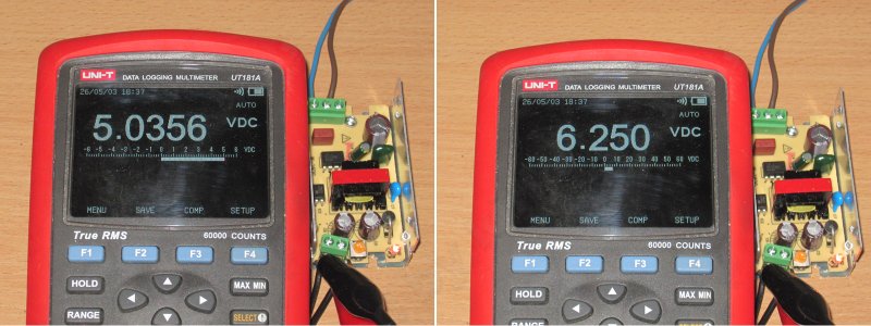
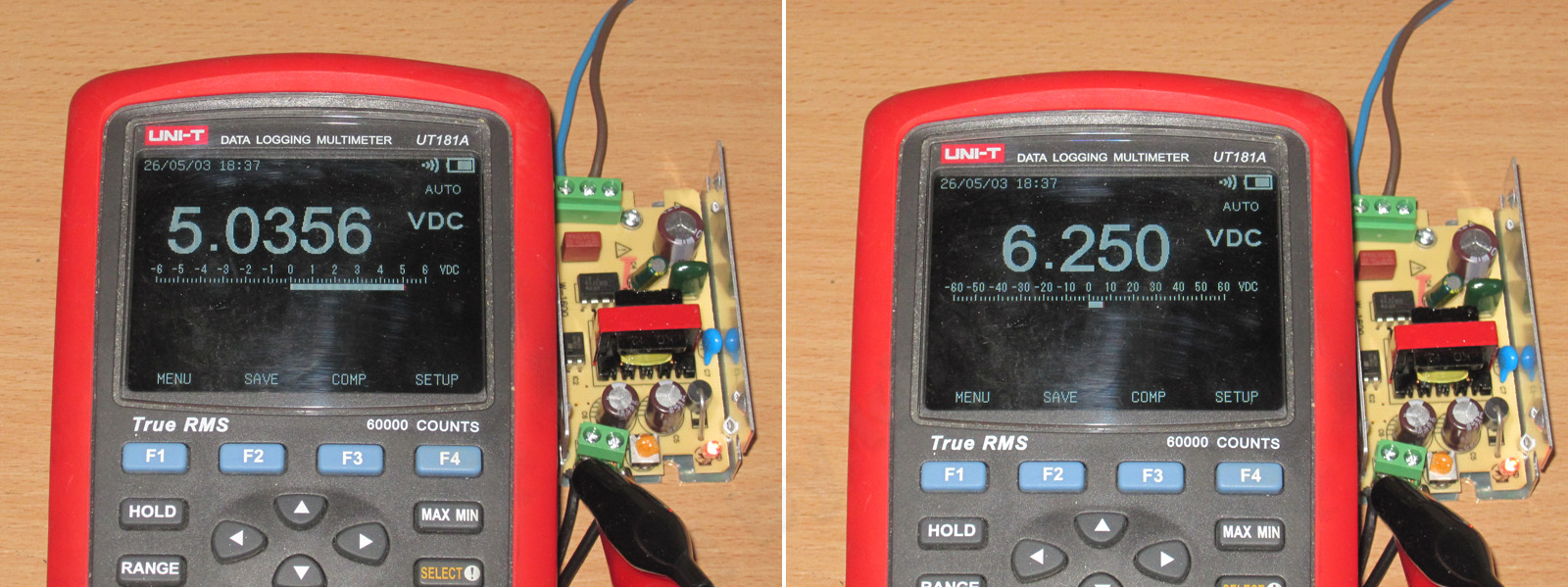
When I first turned on the power supply, I was surprised to see about 5.5 V at the output, which is clearly too high. Then I was even more surprised: the adjustment simply won't let you set it below 5.03 V. I've never seen that before.
Anyway, I turned it all the way down and continued testing at that setting.
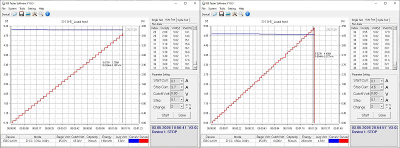
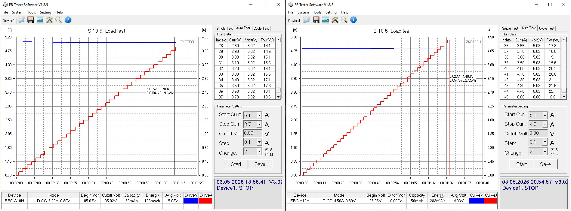
I usually test load capacity by gradually raising the upper limit, but on the first test the power supply easily exceeded my optimistic 3.7 A, so I had to raise the limit. The protection kicked in at 4.4 A.
The protection current seems a bit high to me, but this unit uses a dedicated controller that also provides thermal protection, so there's no need to worry.
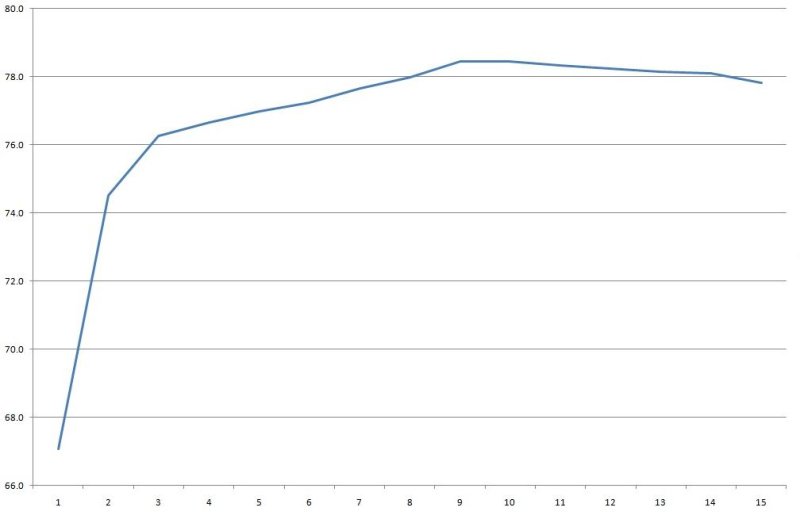
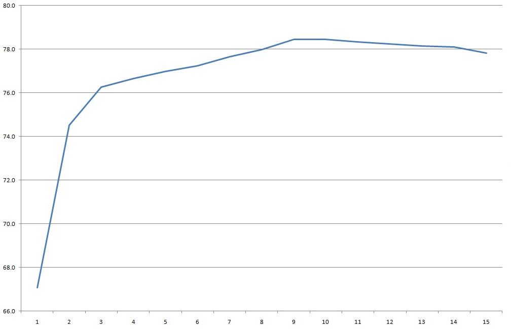
Efficiency was measured from 0.2 to 3 A in 0.2 A increments and came out at about 78%. That's a bit low, but given the low output voltage and the power supply's modest power rating, it's quite acceptable.
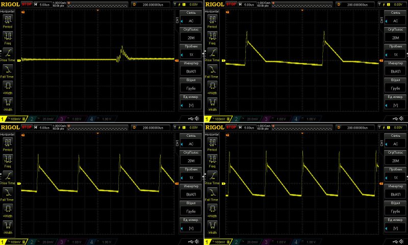
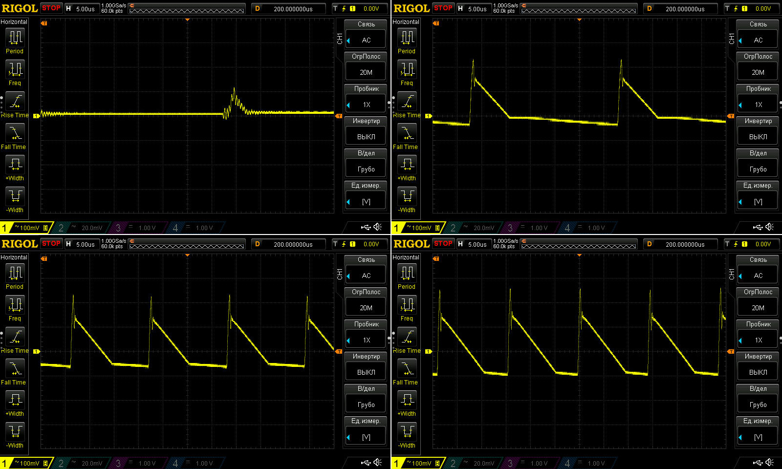
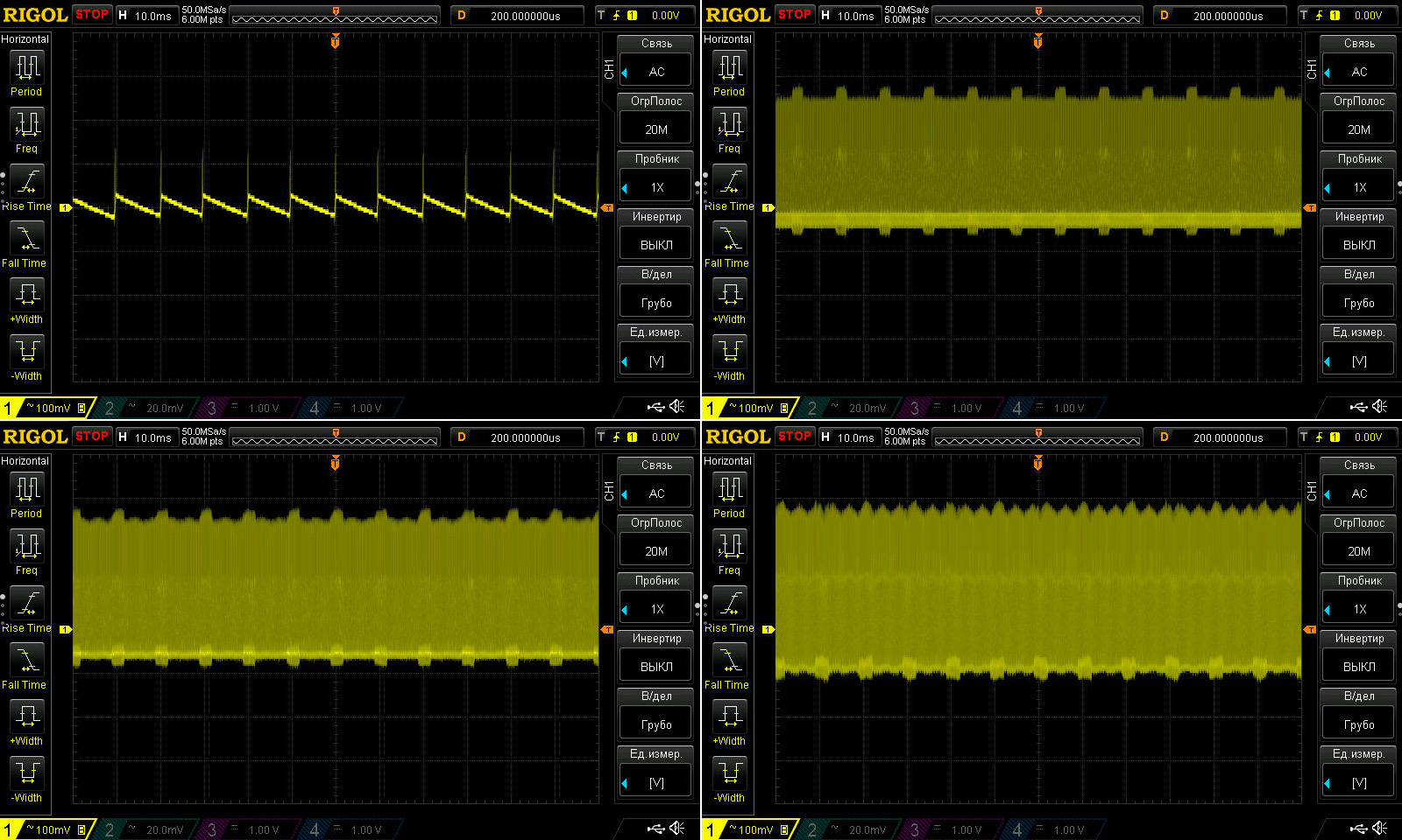
Ripple with no load and at currents of 1, 2, and 3 A.
At the rated 2 A, the ripple is just about acceptable: 200/300 mV. At 3 A it's a little higher, but still tolerable in principle. If I were the manufacturer, though, I'd add at least a basic filter or replace these two capacitors with a single polymer capacitor. The cost would be about the same, with lower ripple and a longer service life.
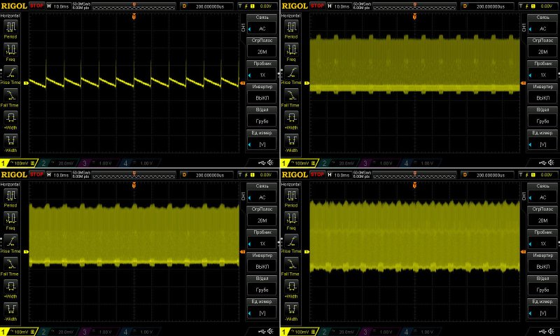
No complaints about the low-frequency ripple.
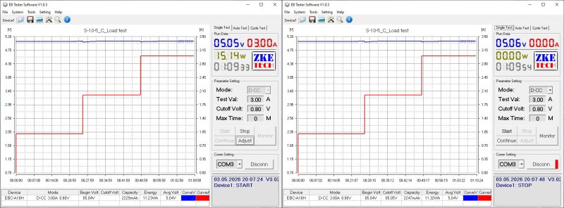
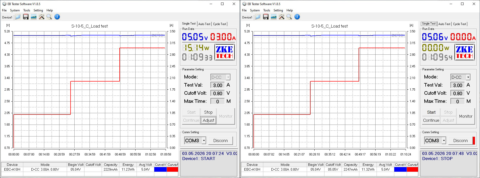
Load testing was carried out in three stages, at currents of 1, 2, and 3 A.
The output voltage barely changes with load, and it barely changes with temperature either. The 10–20 mV of fluctuation is insignificant.
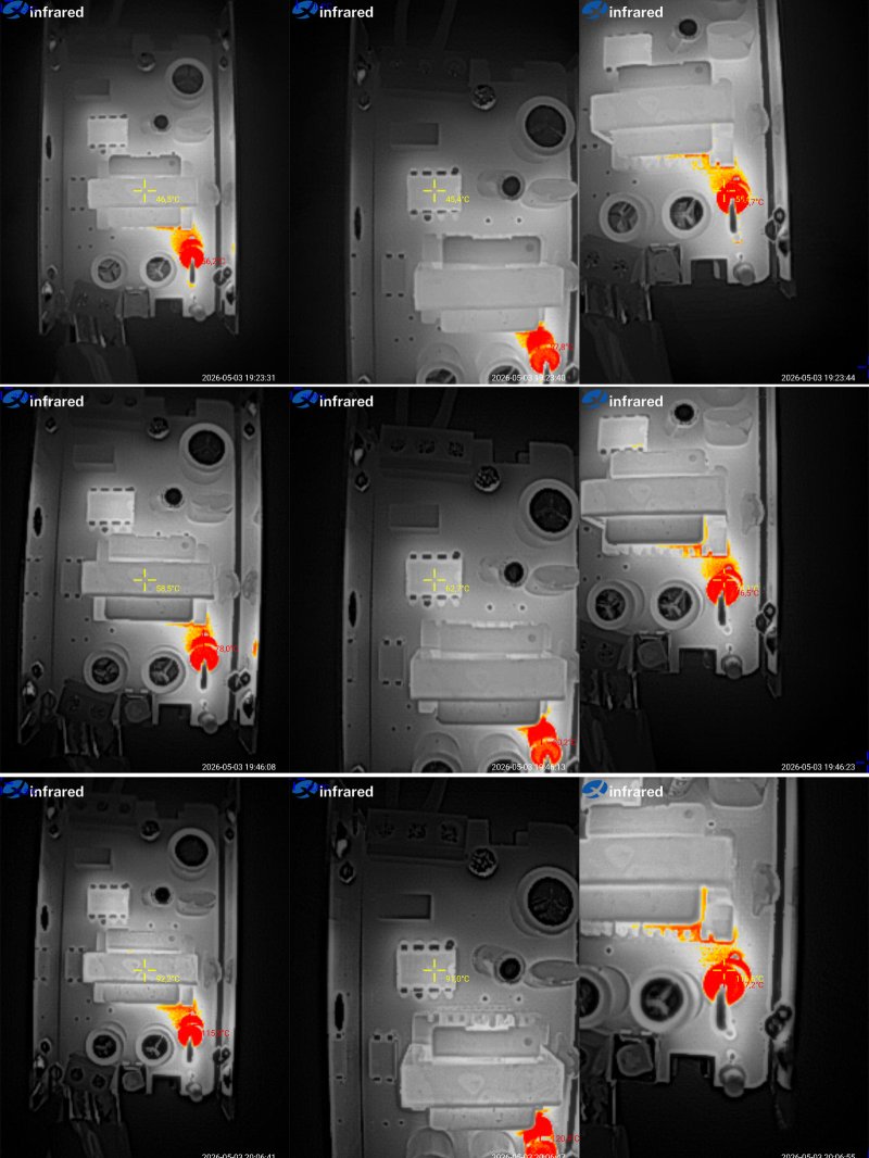
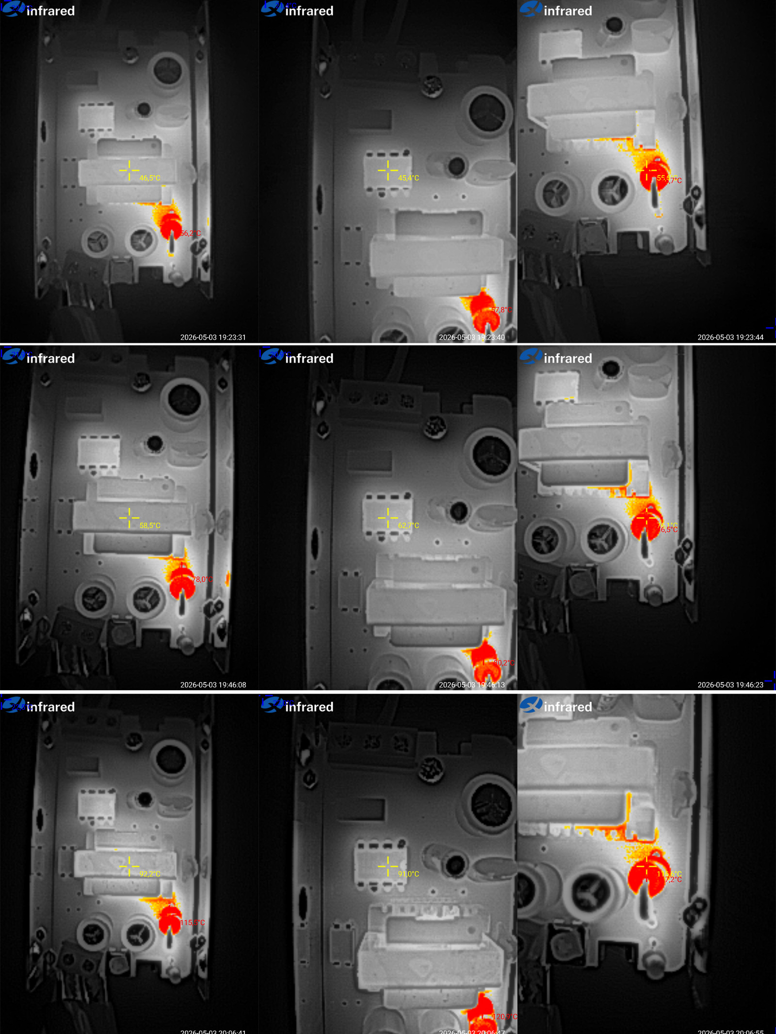
Temperature readings:
1 A — transformer and PWM controller around 45 °C, output diode 56 °C. Excellent.
2 A — transformer 59 °C, PWM controller 63 °C, output diode 76 °C. Also excellent.
3 A — transformer and PWM controller around 92 °C, output diode 117 °C. Just about acceptable, but since this is 150% of the rated load, still excellent.
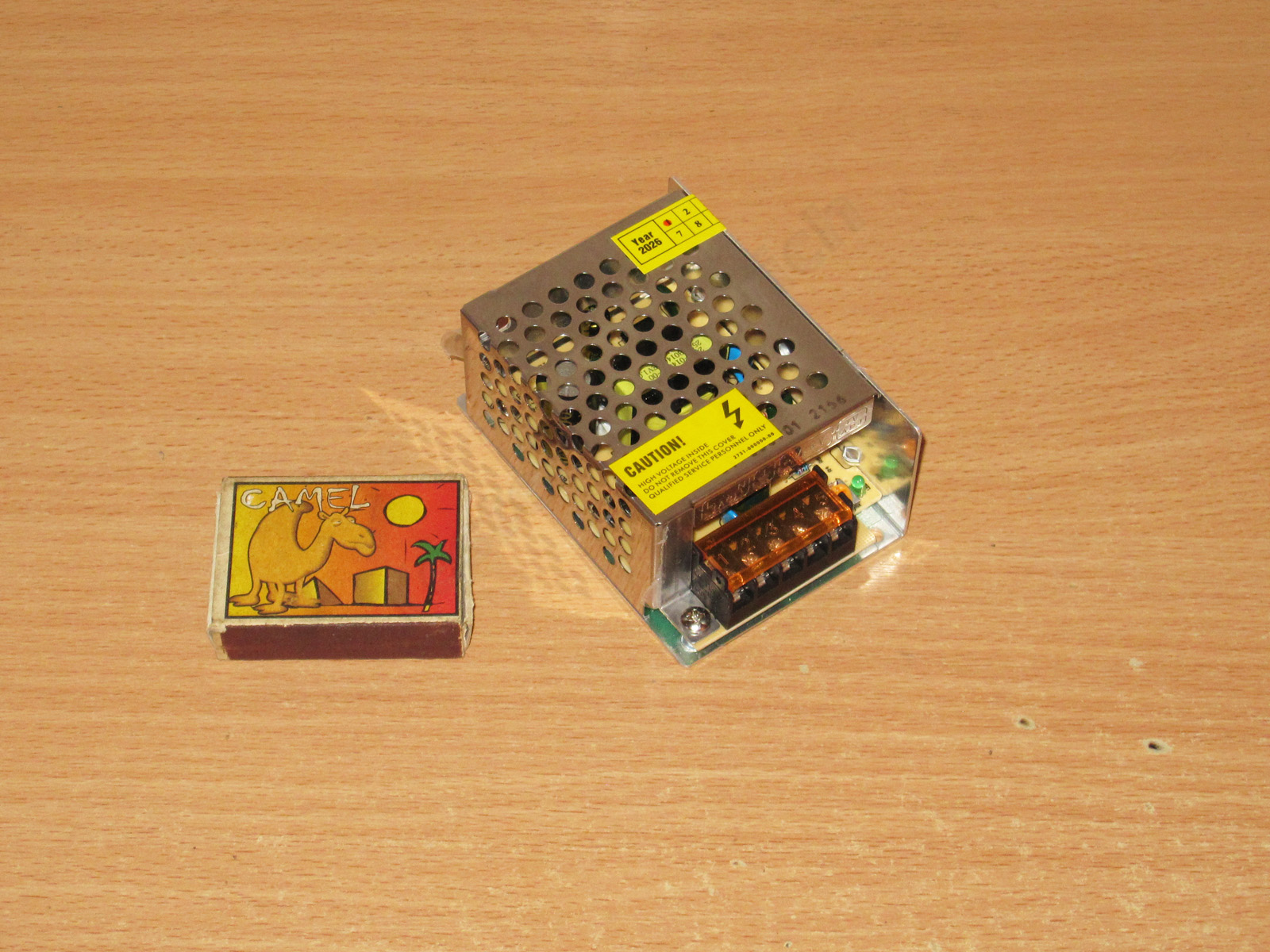
The second model is more powerful, rated at 25 W, and the case format is noticeably different.
Case dimensions: 85 × 58 × 38 mm.
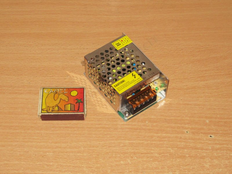
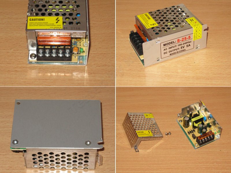
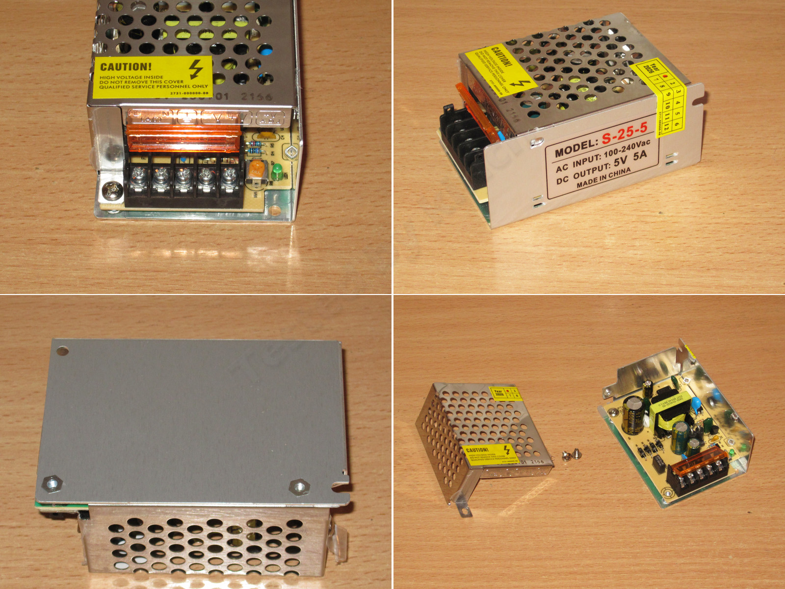
A typical terminal block, adjustment knob, LED, and a very typical way of opening it. Anyone who's ever taken apart one of these power supplies will know the drill.
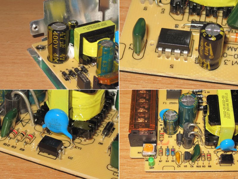
The layout is also typical, with plenty of room for the components, but there's no input filter at all.
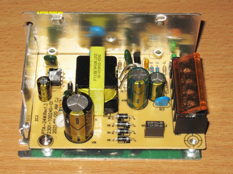
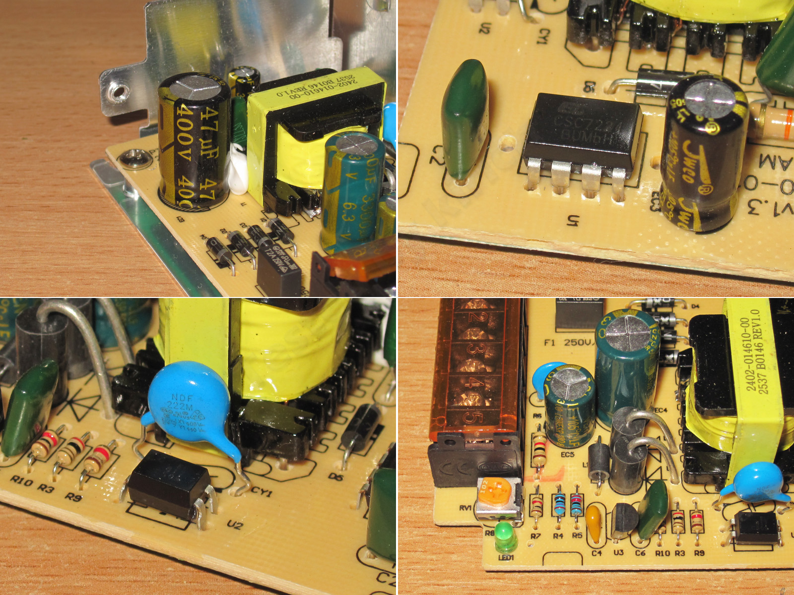
1. The input capacitor is rated at 47 µF, but the unusual font and suspiciously small size for that capacitance made me doubt it.
2. This model is based on the CSC7224 chip, a PWM controller with an integrated high-voltage transistor. It is designed for power supplies rated at up to 18 W over an input range of 85–265 V. With a narrower input range, the power rating should be closer to 24 W, which is near the advertised figure.
3. A Y capacitor is present
4. The output has two diodes in parallel, as well as two capacitors, 3300 µF and 1000 µF, rated at 6.3 V. They even fitted a small inductor.
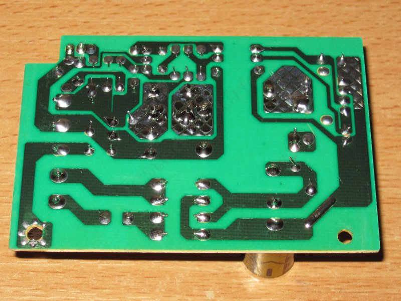
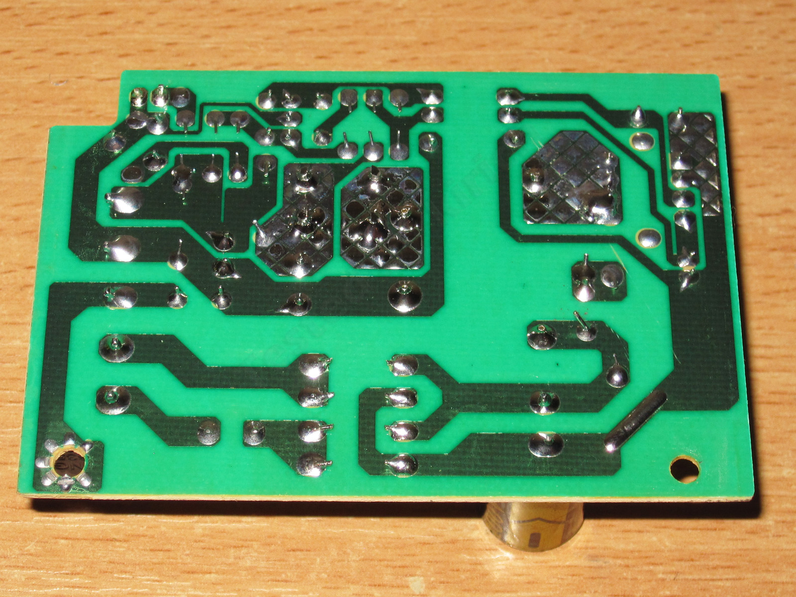
I have no major complaints about the circuit board, although some of the clearances could have been a bit larger.
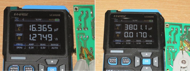
The input capacitor's actual capacitance is about 16 µF, so it's a relabeled 22 µF capacitor. That clears things up.
The output capacitors have a combined capacitance close to 4000 µF, which is quite enough for the advertised 5 A output current.
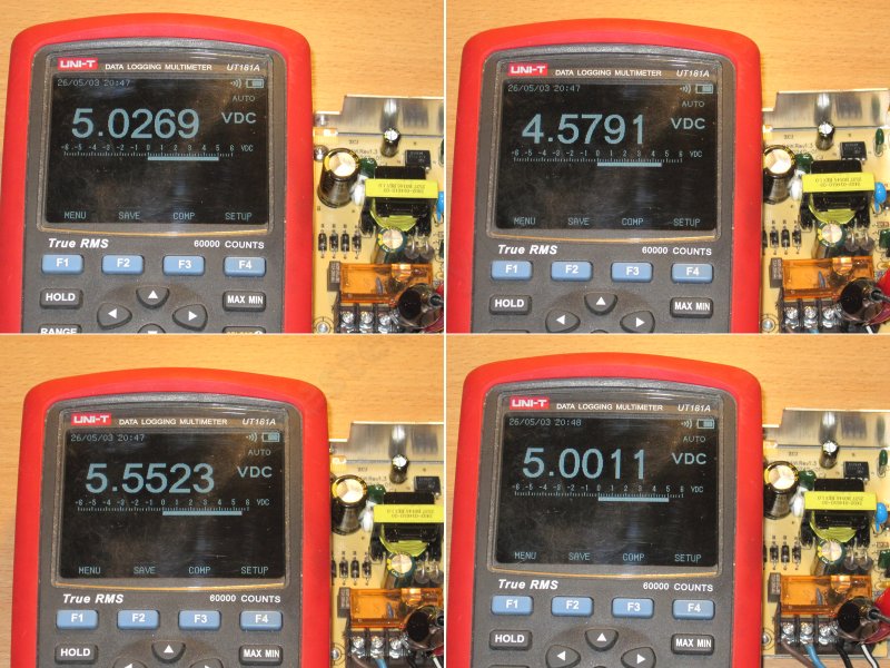
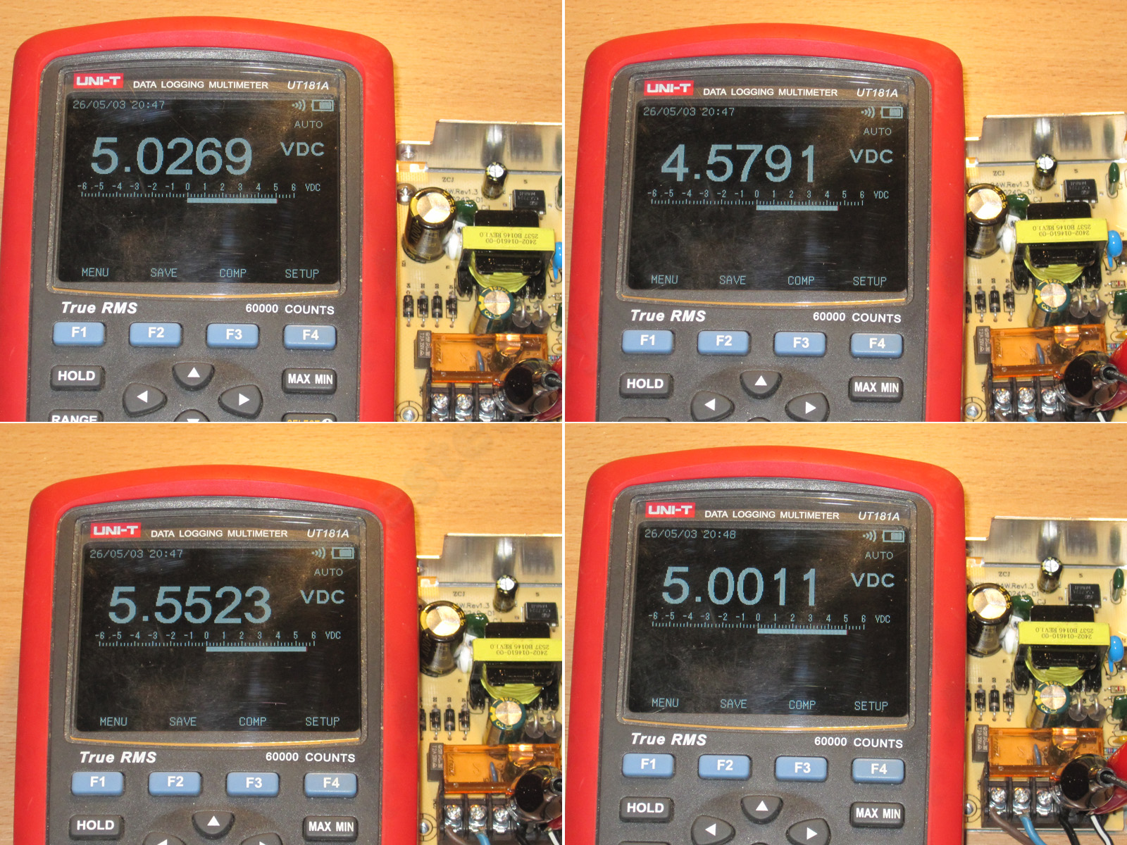
The voltage adjustment works fine here. It was 5.03 V out of the box, and can be adjusted from 4.58 to 5.55 V. I had no trouble setting it to 5.001 V.
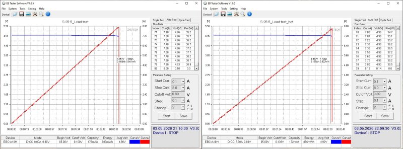
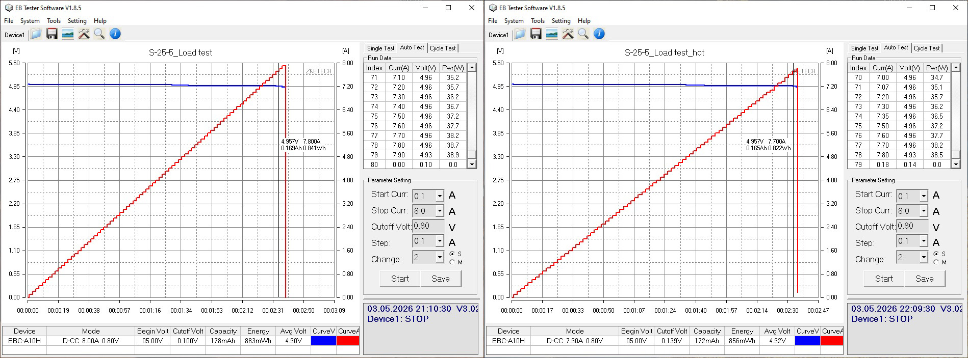
Given the chip they used, I expected the overcurrent protection threshold to be lower. In reality, it trips at 7.8 A when cold and 7.7 A when hot. But that's about 38–39 W, compared with the advertised 25 W, so perhaps it's fine.
The voltage regulation is very good, by the way.
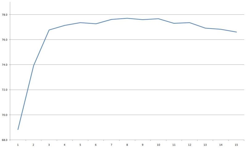
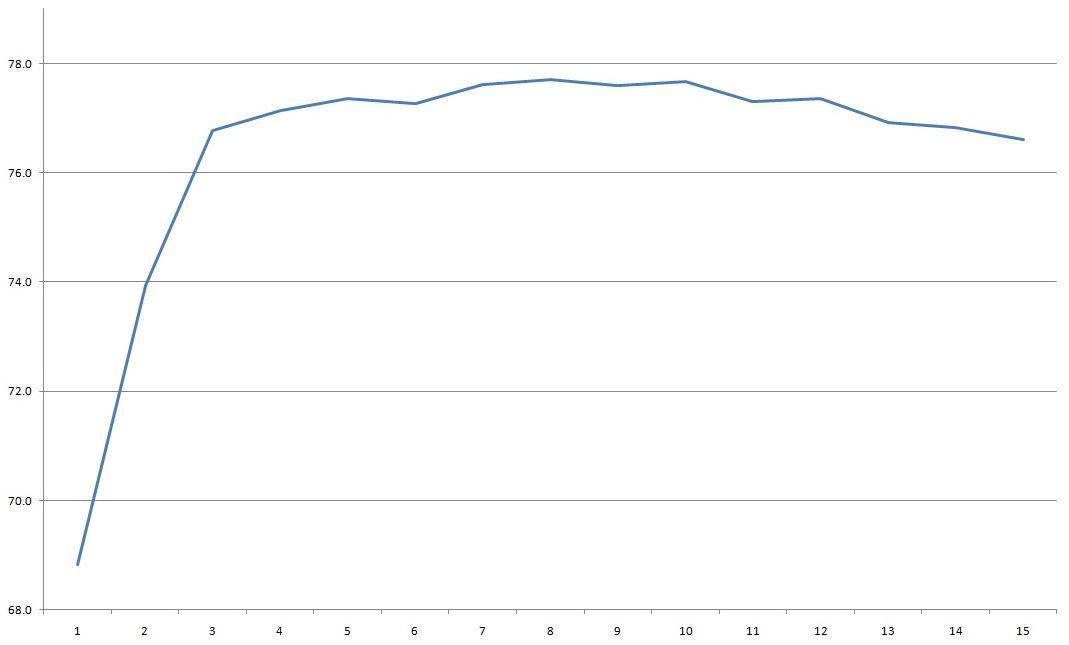
Efficiency measured from 0.4 to 6 A in 0.4 A increments. The result is about the same as for the previous model: it could be better, but it's acceptable.
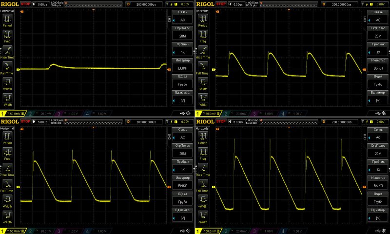
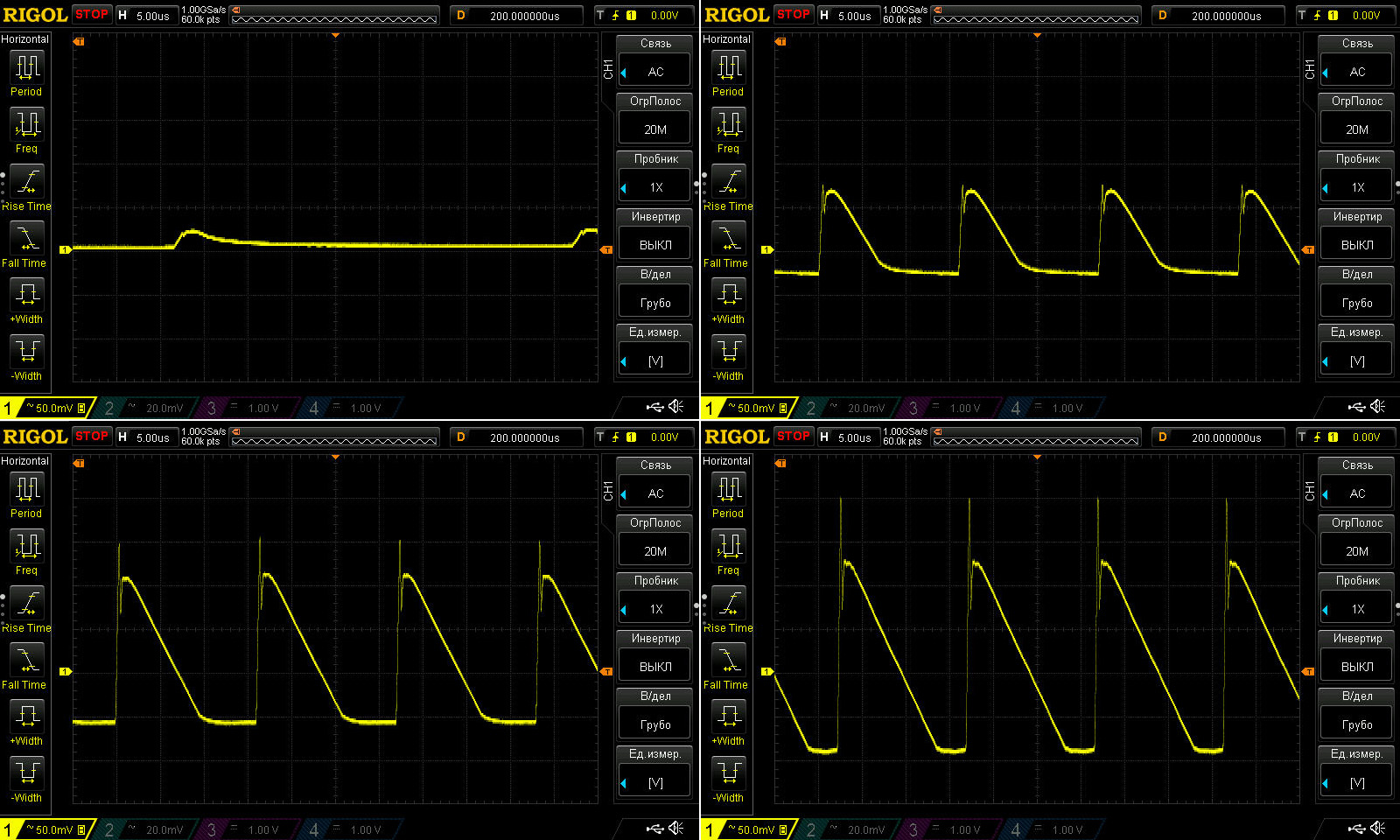
Ripple with no load and at currents of 2, 4, and 6 A.
For a 5 V output, it's rather high: 150/200 mV at 4 A and 220/280 mV at 6 A. It's not exactly a disaster, but considering there's a tiny filter here and the output capacitance is quite substantial, it's still a lot.
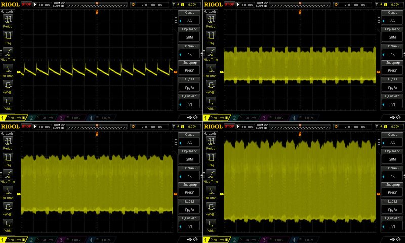
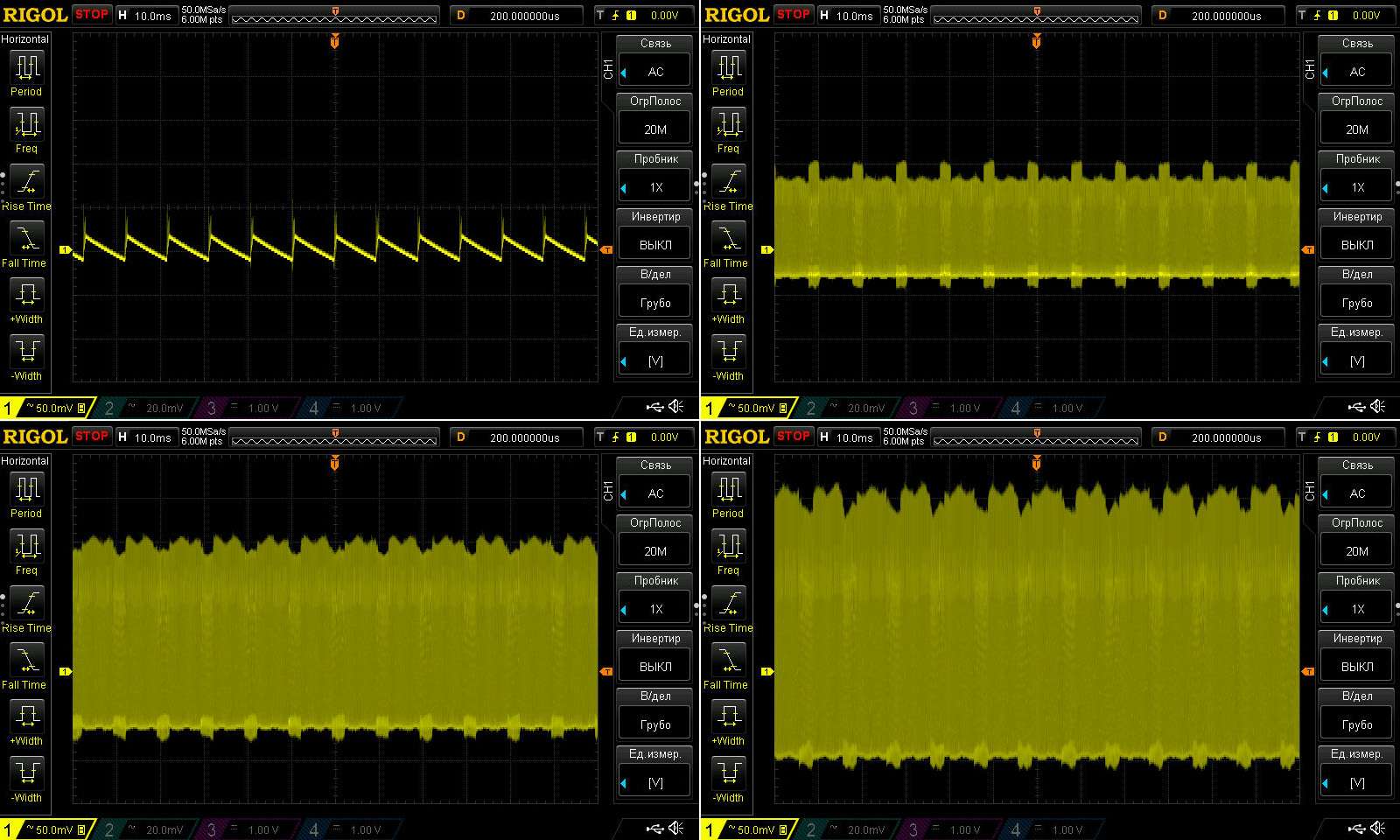
At low frequency, we see the same peak-to-peak amplitude, but the low-frequency ripple is small, so this is OK.
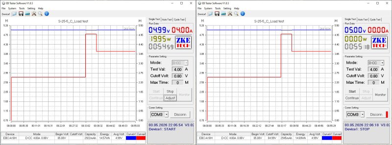
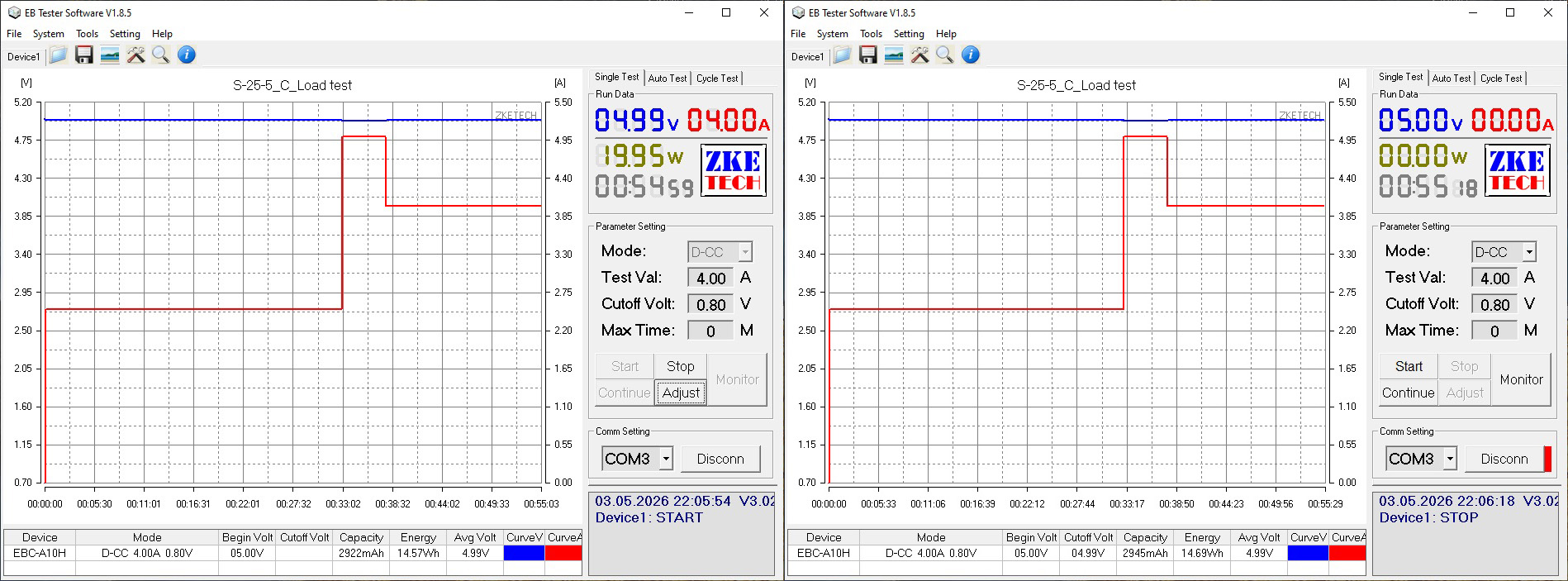
The load test was run at 2.5, 5, and 4 A. You'll understand why later.
I have no complaints at all about voltage stability. By the way, the lower the power supply's output voltage, the more critical this becomes.
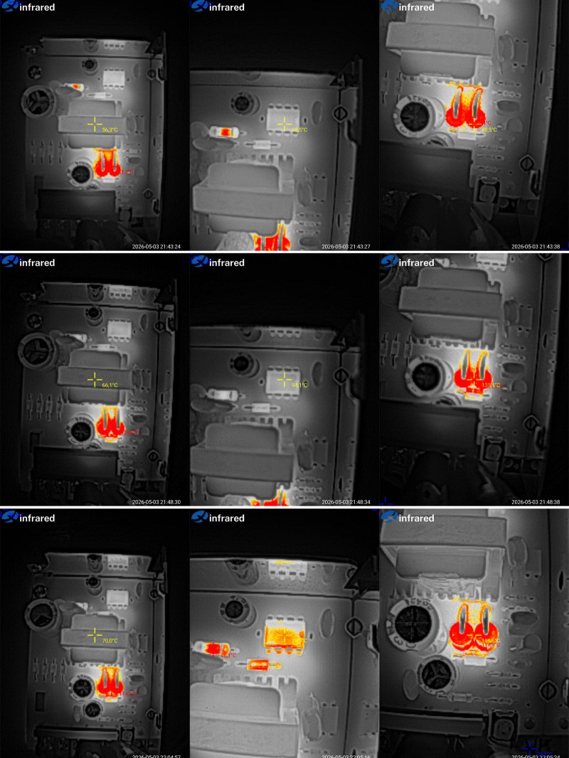
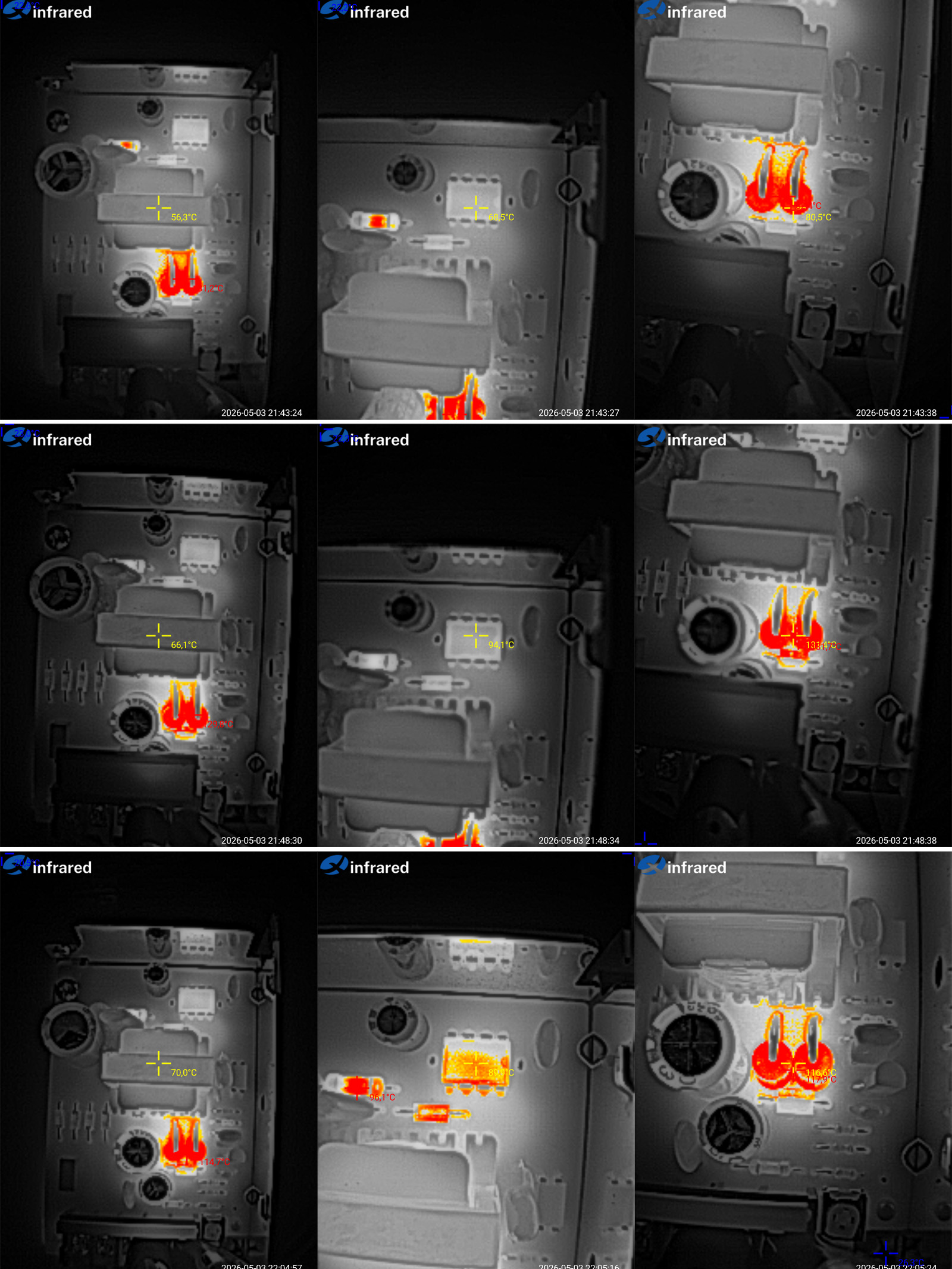
Temperature test.
At 2 A: transformer 56 °C, PWM controller 89 °C, diodes 80 °C. That's rather hot.
At 5 A: transformer 66 °C, PWM controller 94 °C, but the diodes reach 130 °C—far too hot. So I reduced the current to 4 A for the next test.
At 4 A: transformer 70 °C, PWM controller 90 °C, diodes 118 °C.
So the actual maximum continuous current here is no more than 4 A, limited by the output diodes. You might ask why the previous model, with one diode, managed 3 A, while this one reaches the same temperature at 4 A with two diodes—shouldn't it manage 6 A? It's quite simple: although there are two diodes, they're right next to each other and heat one another, so the current rating is only a little higher than the previous model's.
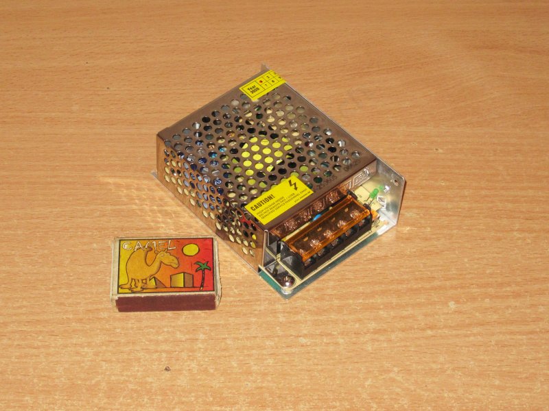
The third test subject: 40 W, 8 A.
It's basically similar to the previous one, but the dimensions are now 110 × 77 × 37 mm.
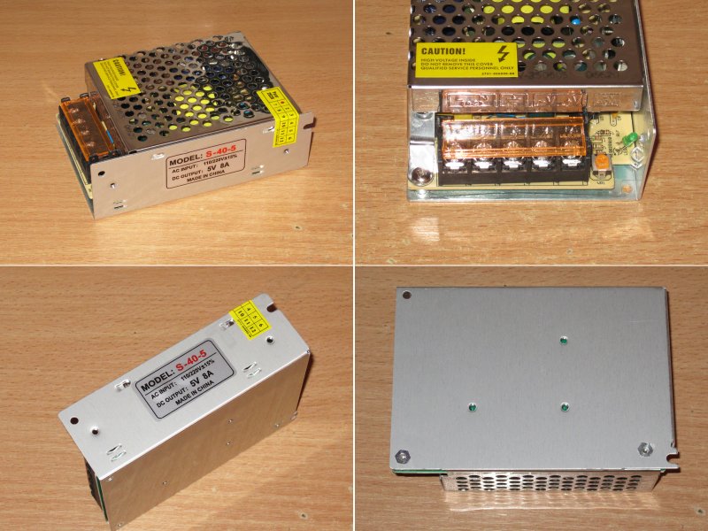
The case, terminal block, and so on are very similar, but this one has extra mounting holes on the bottom, which can sometimes come in handy.
Here are all three models side by side to show the difference in size.
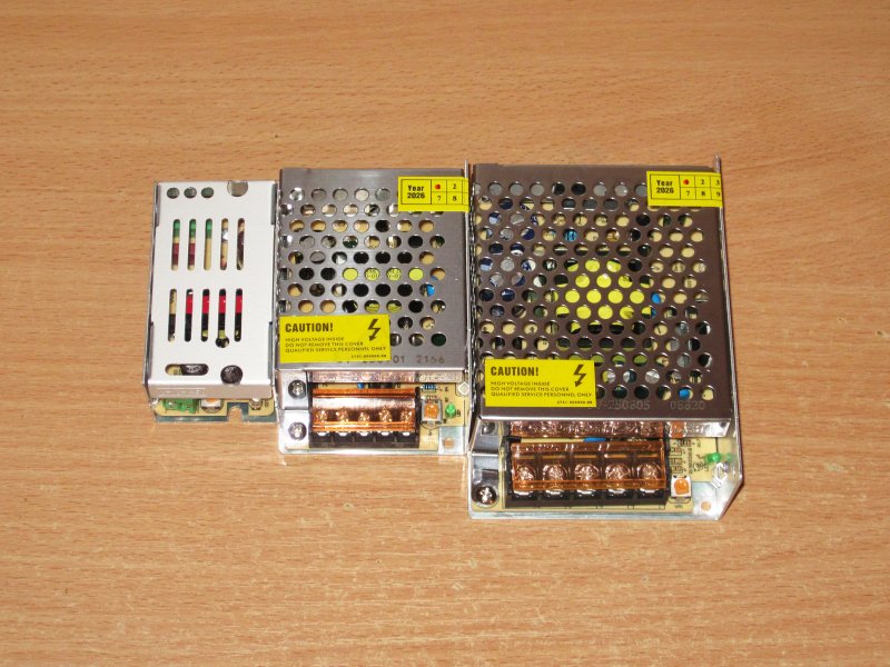
Let's open it up and see what's inside.
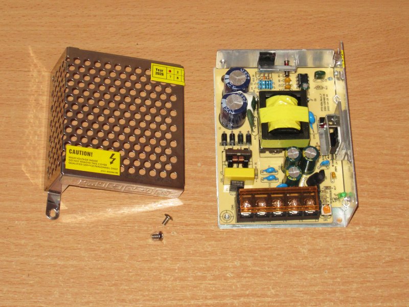
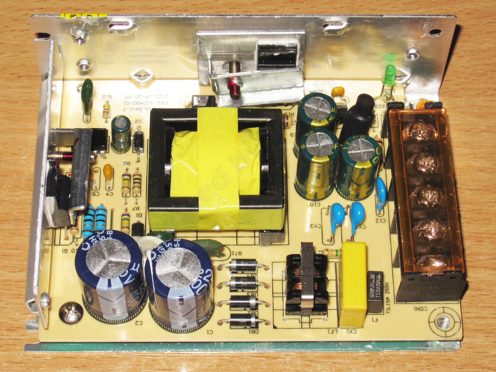
This one is better: a decent-sized transformer, a PWM controller with an external transistor, and the output diode is bolted to the case (no idea what stopped them doing that on the previous model). They even fitted an input filter and a thermistor—now that's luxury :))))
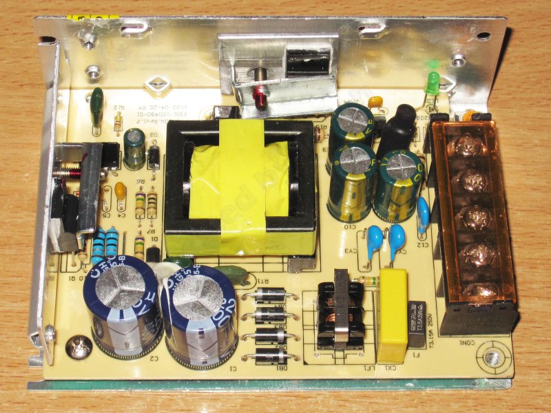
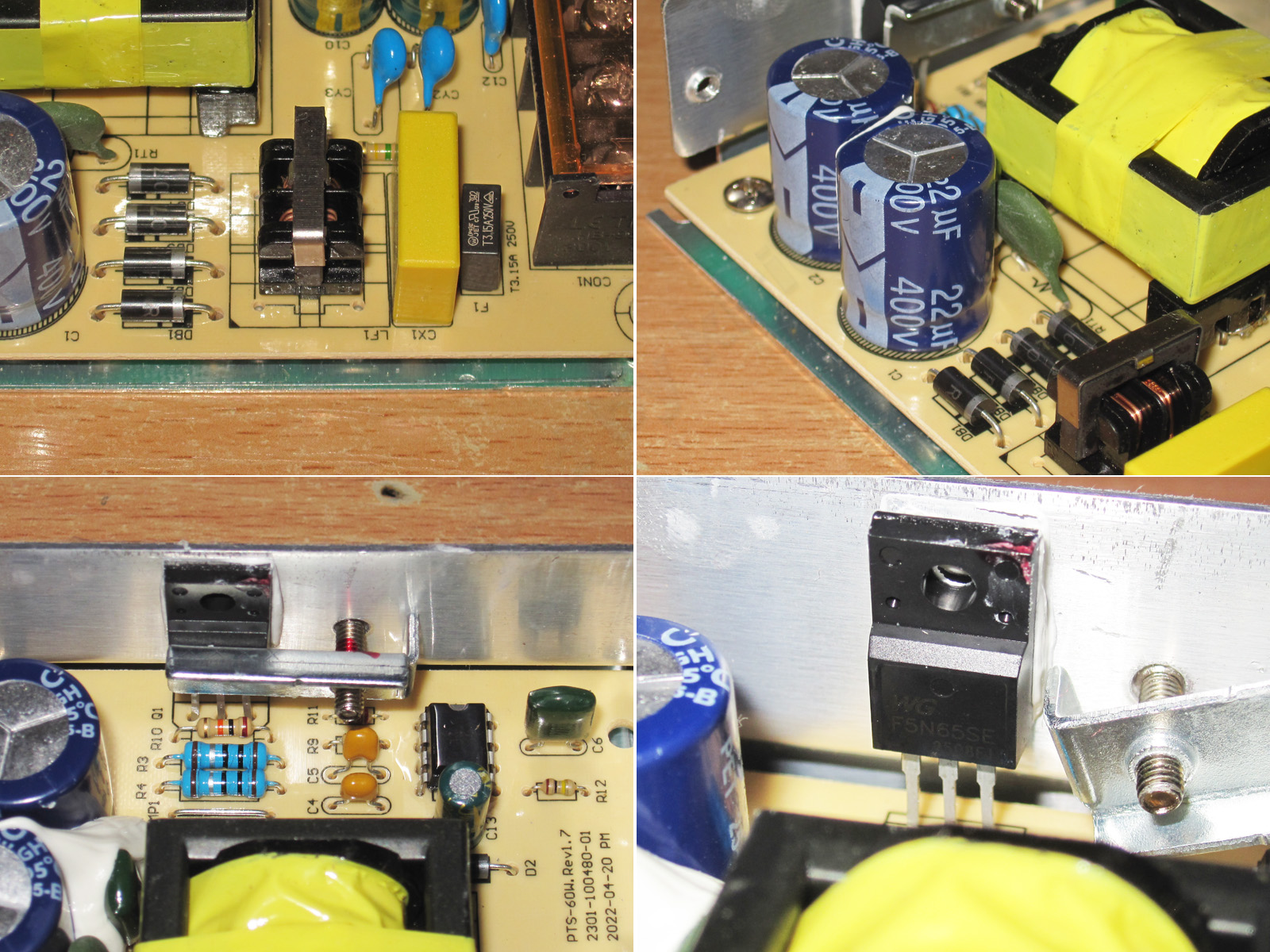
There are two 22 µF capacitors on the input, the PWM controller is coated in lacquer, and the transistor is rated for 5 A and 650 V. Nothing unusual.
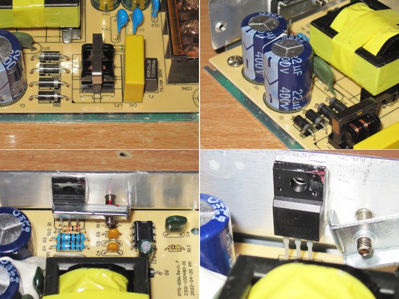
A Y capacitor is present, and the rectifier bridge is rated for 20 A and 45 V—perfectly fine.
There are three 3300 µF, 10 V capacitors on the output, which is quite enough. They also fitted an output inductor to reduce ripple.
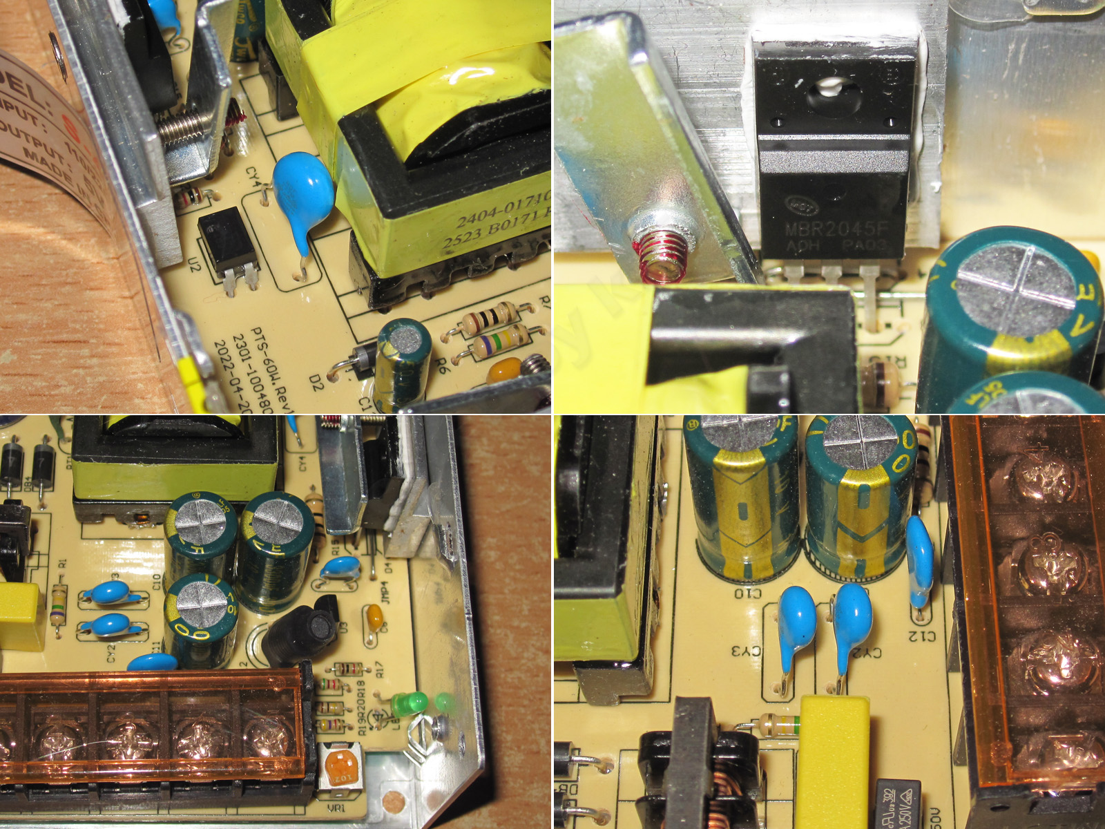
There are additional noise-suppression capacitors too: two Y capacitors and one regular one. That's fine, since the regular one is essentially in series with a Y capacitor.
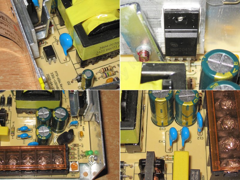
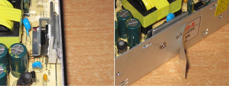
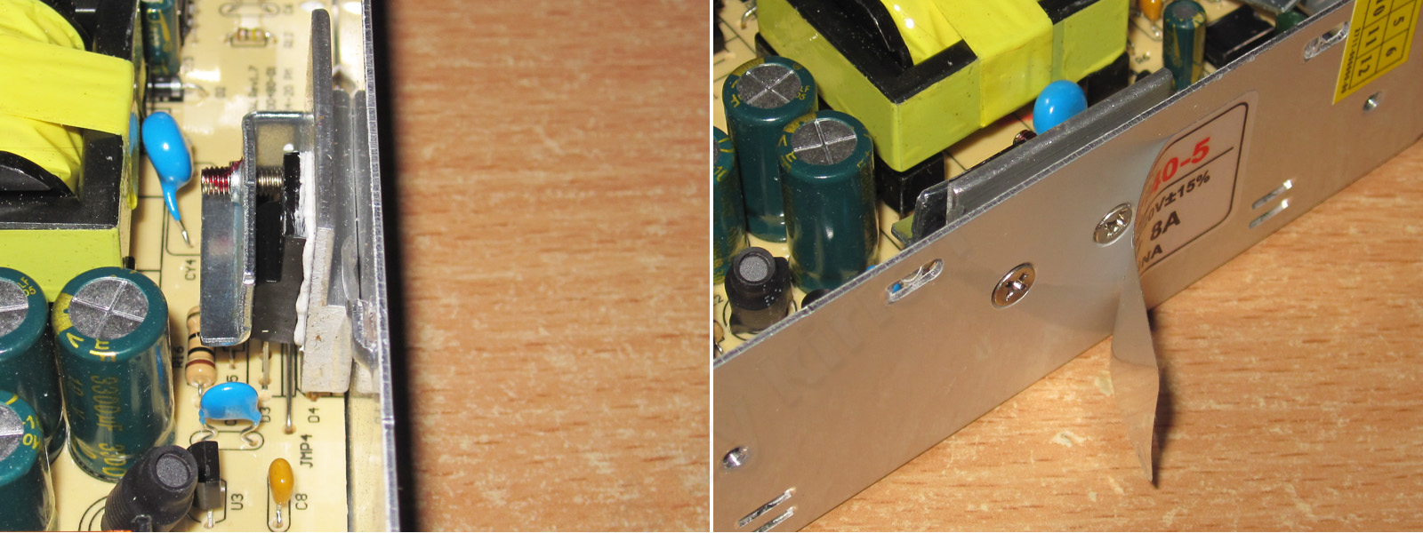
It's interesting that they fitted a heat spreader under the output diode even though the current is relatively low. I don't like these in the "Chinese" style, though, where they try to attach one crooked part to another that's just as crooked—and don't even use thermal paste.
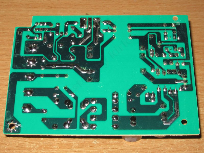
I have no complaints about the board's safety or workmanship.
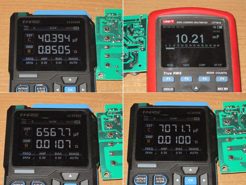
I did all the measurements with my multimeter, using the LCR meter mostly alongside it, but this is where I ran into the first oddity.
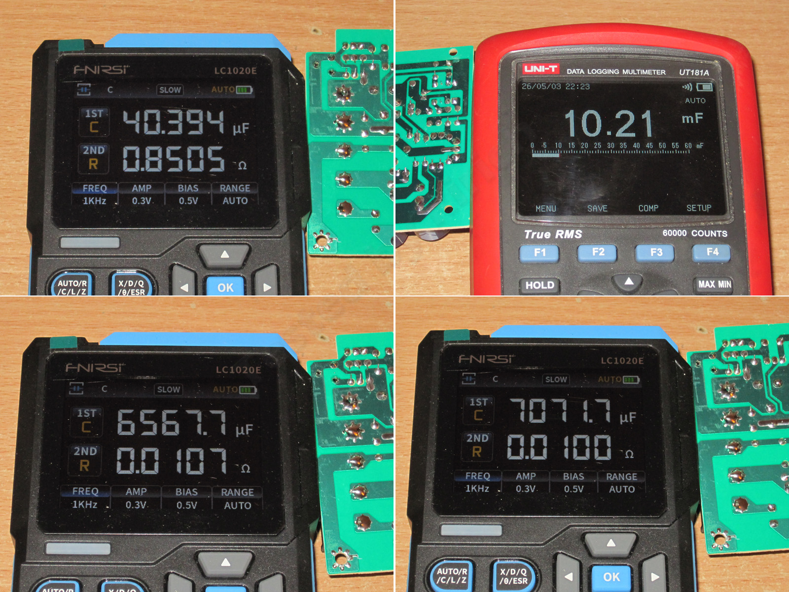
The input capacitors are fine—in fact, excellent. 40 µF for a stated 2 × 22 µF is good.
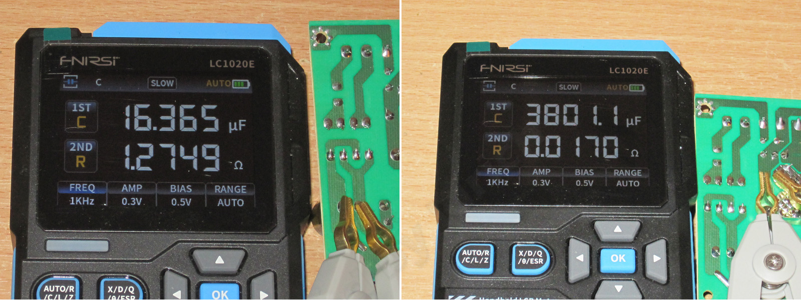
But the output capacitors were puzzling. The calculated value should be around 10000 µF, and the multimeter showed roughly that. Fnirsi, however, not only disagreed completely, but its readings were all over the place, like a sailor after a night at the bar. All in all, I'm more inclined to trust the multimeter here.
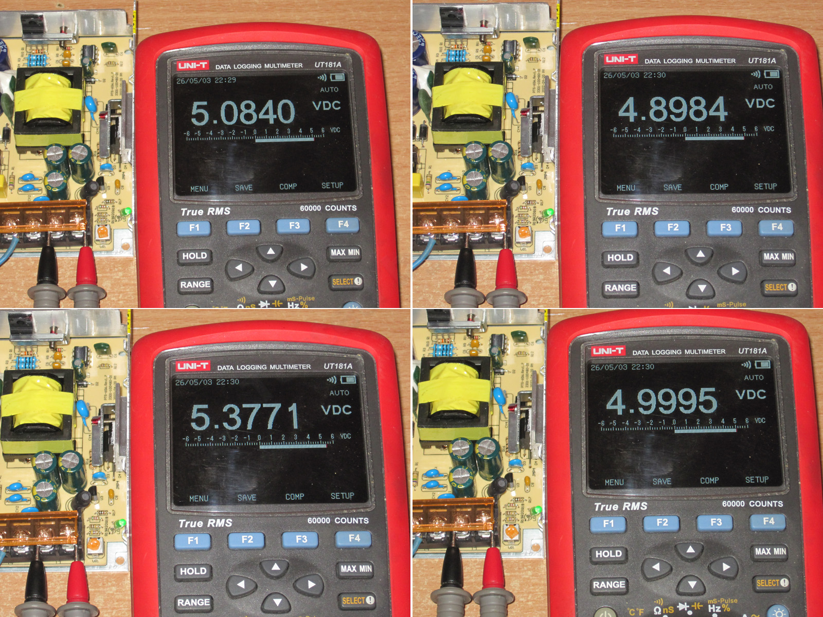
The initial output voltage was 5.08 V. The adjustment range is fairly narrow, from 4.9 to 5.38 V, but since the adjustment was smooth, I had no trouble setting it to almost exactly 5 V.
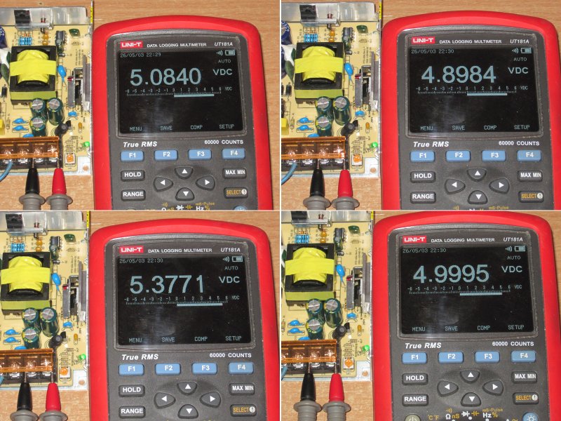
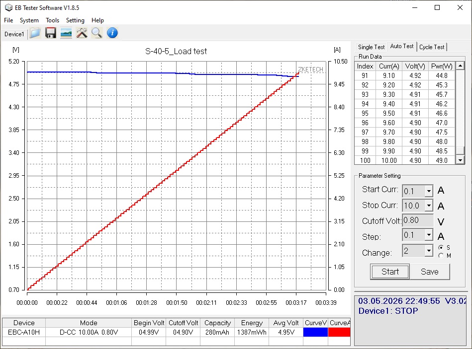
The power supply handled a 10 A load without a fuss, although the output voltage dropped by about 0.09 V—not a major issue, just noticeable.
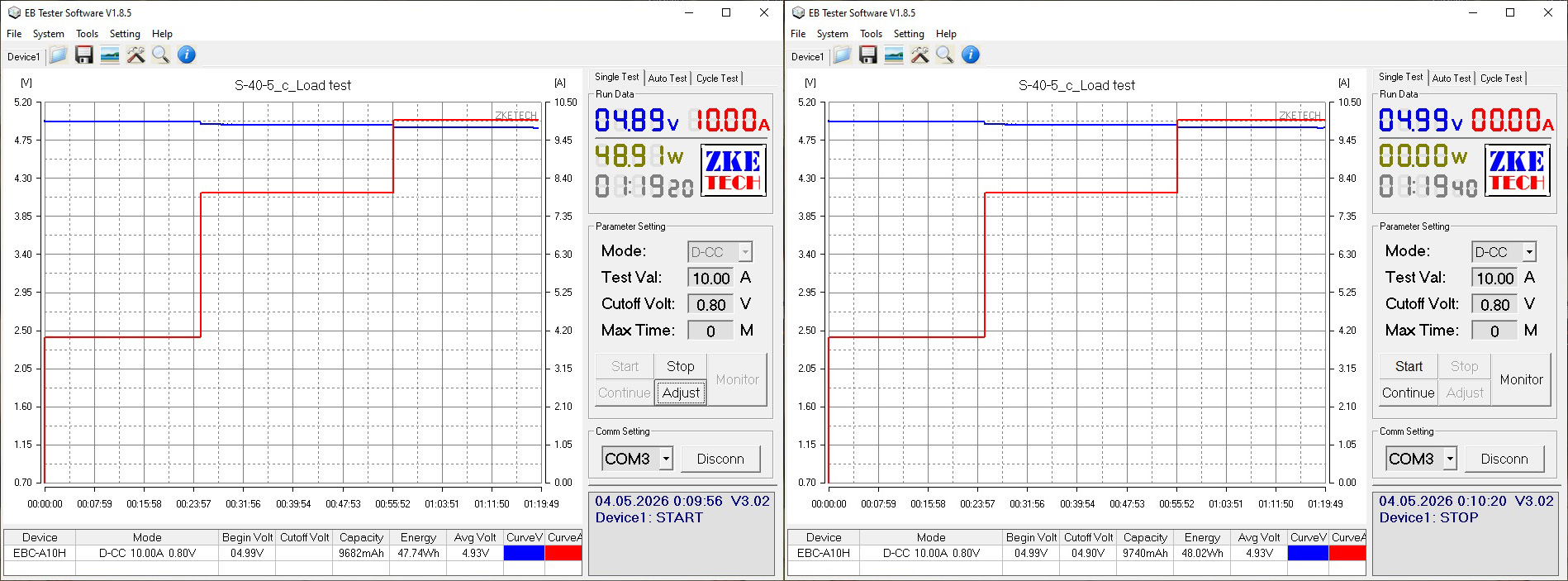
This test was done with a ZKEtech EBC-A10H electronic load, which has a maximum current of 10 A. I wanted to continue testing with an EBC-A40L, but its maximum voltage is 4.7 V, I think. What a shame—it would have been handy for plotting graphs.
I had to connect a more powerful load, which I used for the rest of the tests. The protection kicks in at around 11.5–11.6 A, which is perfectly reasonable for a stated current rating of 8 A.
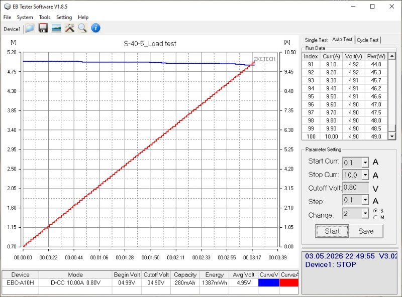
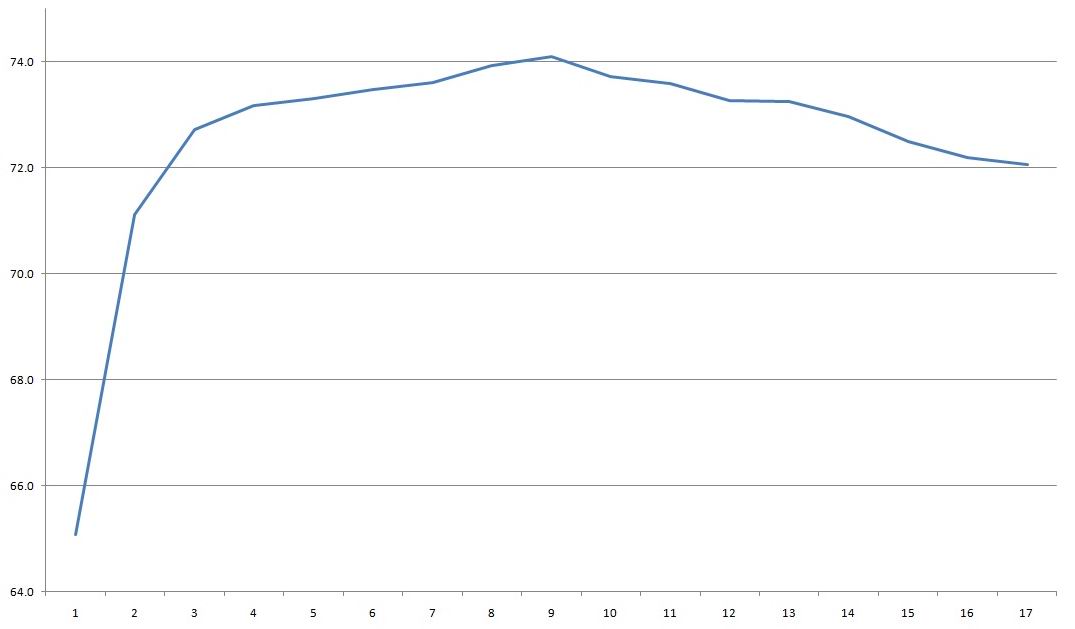
Efficiency was measured from 0.6 to 10 A in 0.6 A increments, with only the final step using 0.4 A increments.
And somehow the result was worse than the previous units: 74% at best, and even that was only at the peak. Otherwise it was lower, closer to 73%.
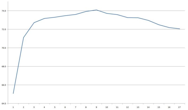
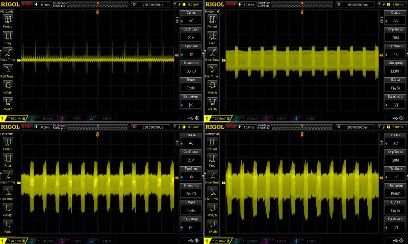
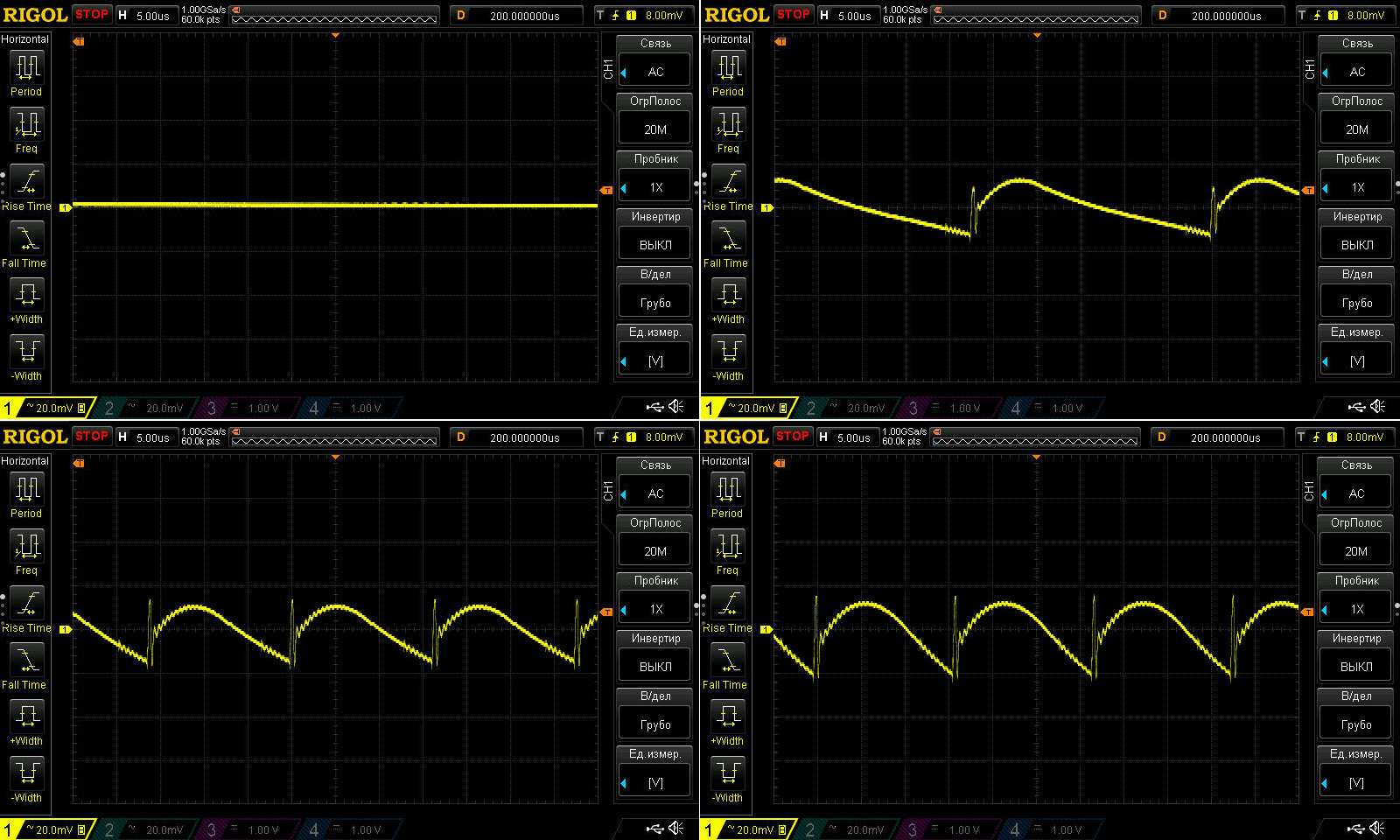
Ripple with no load and at currents of 3, 6, and 9 A.
This is beautiful, though: even at 9 A, ripple is no more than 40 mV, despite the stated maximum current of 8 A.
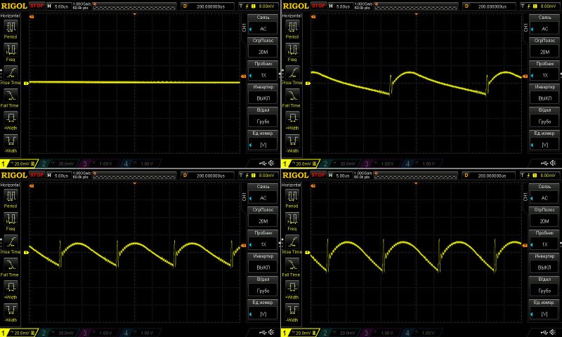
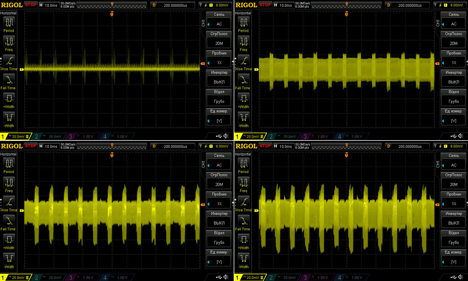
At low frequencies, though, 100 Hz ripple shows up. In absolute terms it's not that large, with a total swing of around 80 mV, but relative to the rest it looks ugly. The input capacitors have enough capacitance for this power level.
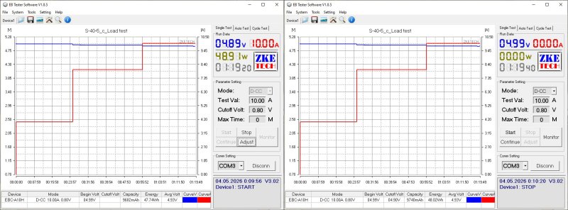
The load test was run in three modes, at 4, 8, and 10 A, for intervals of 20–30 minutes.
The test also showed that the voltage is practically unaffected by temperature, but does vary with load by about 0.1 V. That's within spec, but they could have done better.
Temperatures.
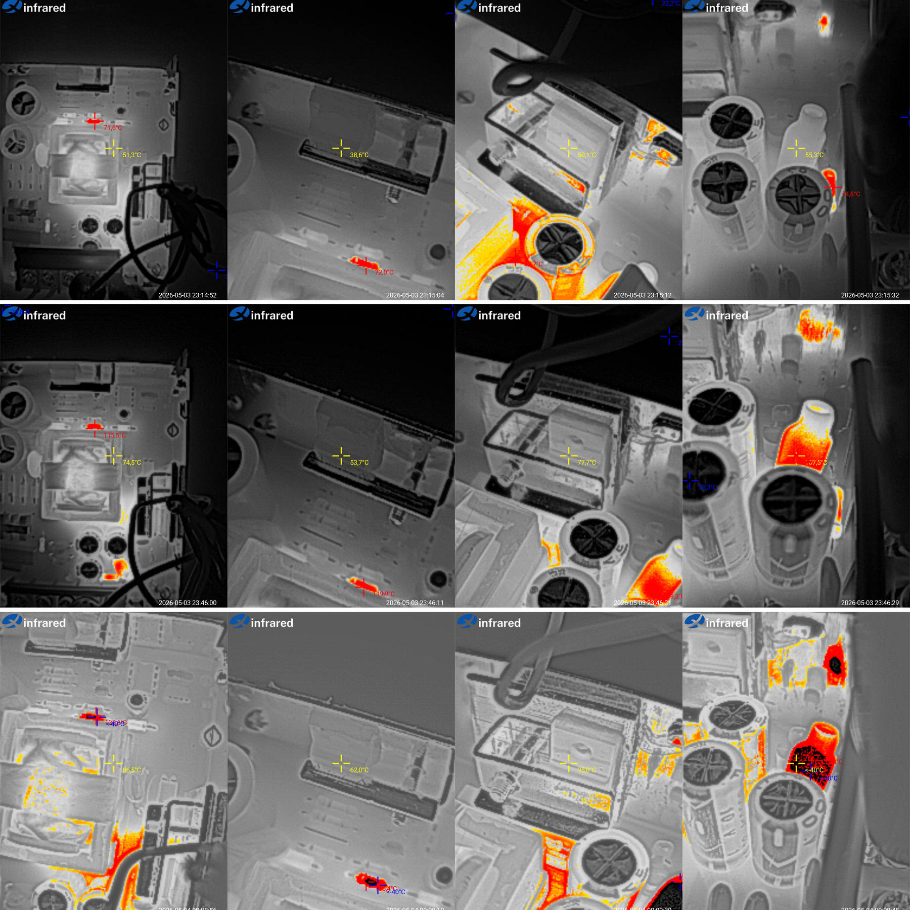
At 4 A: transformer 51 degrees, transistor 39 degrees, output diode 50 degrees, output inductor 55 degrees.
At 8 A: transformer 74.5 degrees, transistor 54 degrees, diode 78 degrees, output inductor 107 degrees. Everything is fine except the inductor.
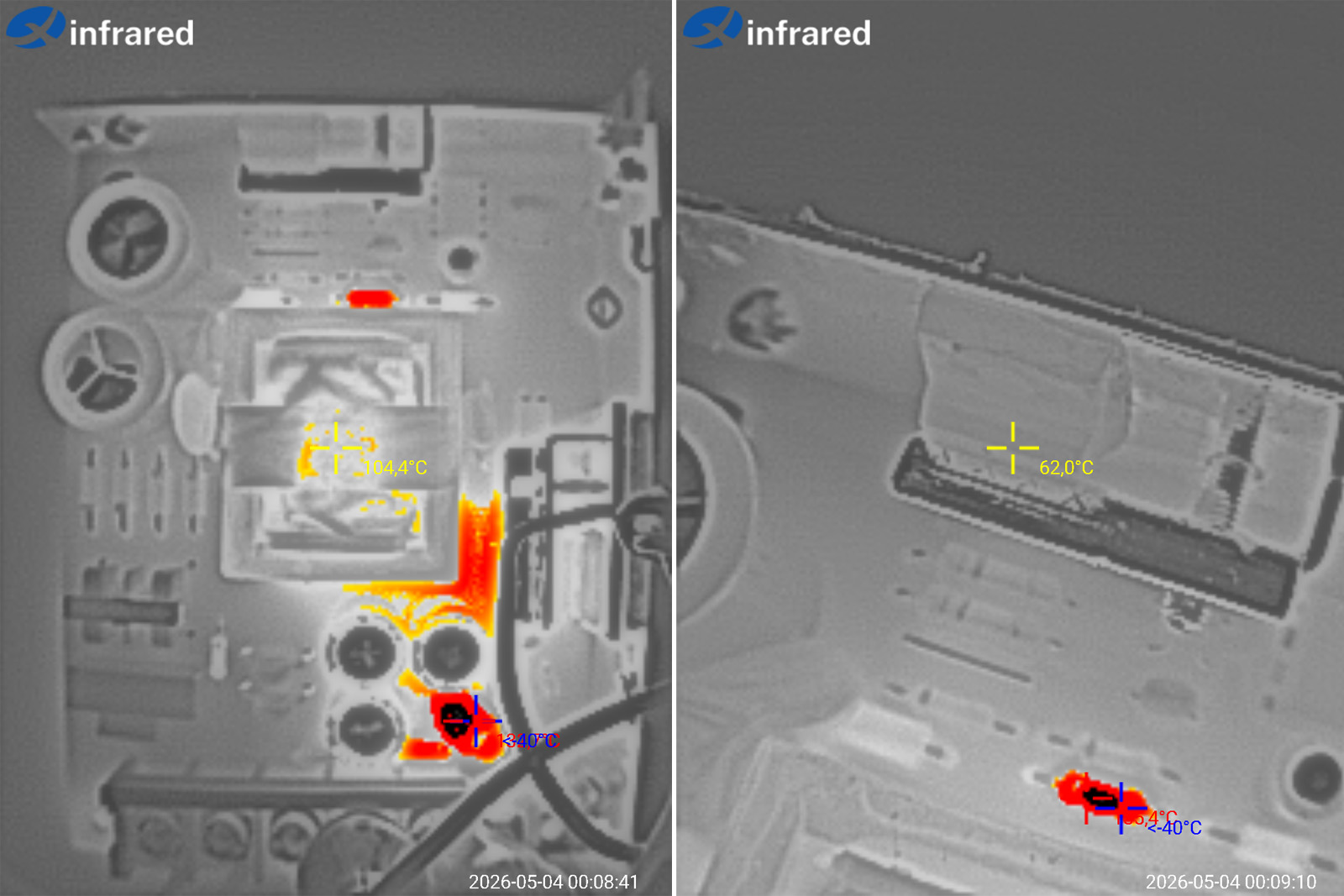
At 10 A: transformer 86.5 degrees, transistor 62 degrees, output diode 95 degrees, inductor temperature exceeded 135 degrees.
Everything is excellent except the inductor. The power supply handles even 10 A with ease, not to mention its rated 8 A, but they could have used an inductor rated for a higher current.
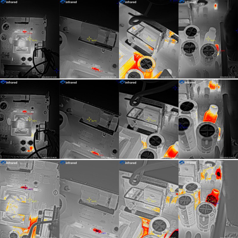
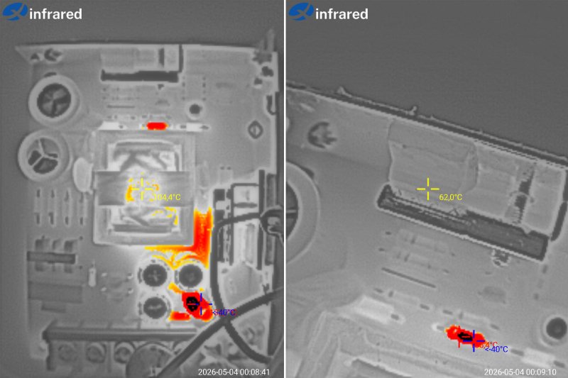
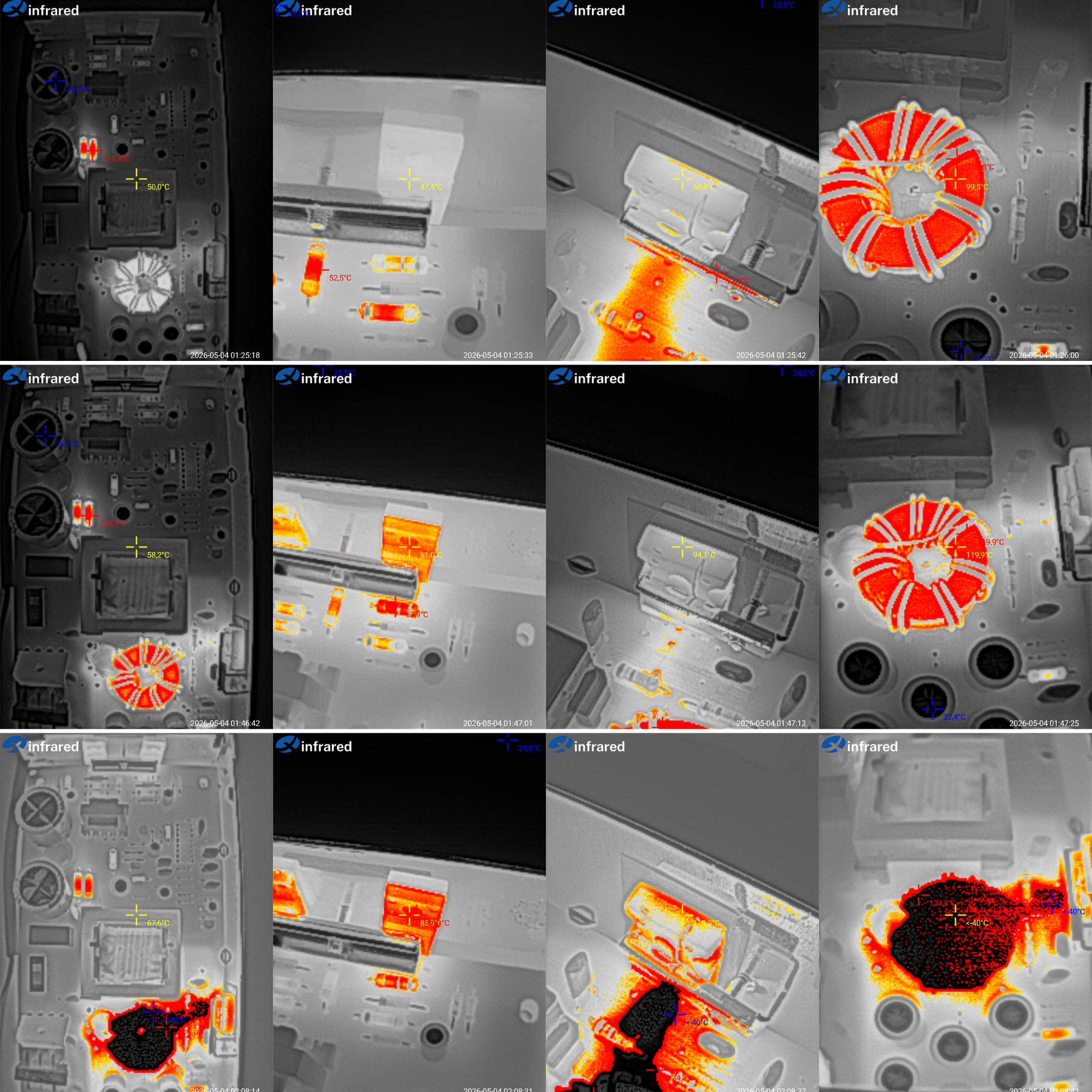
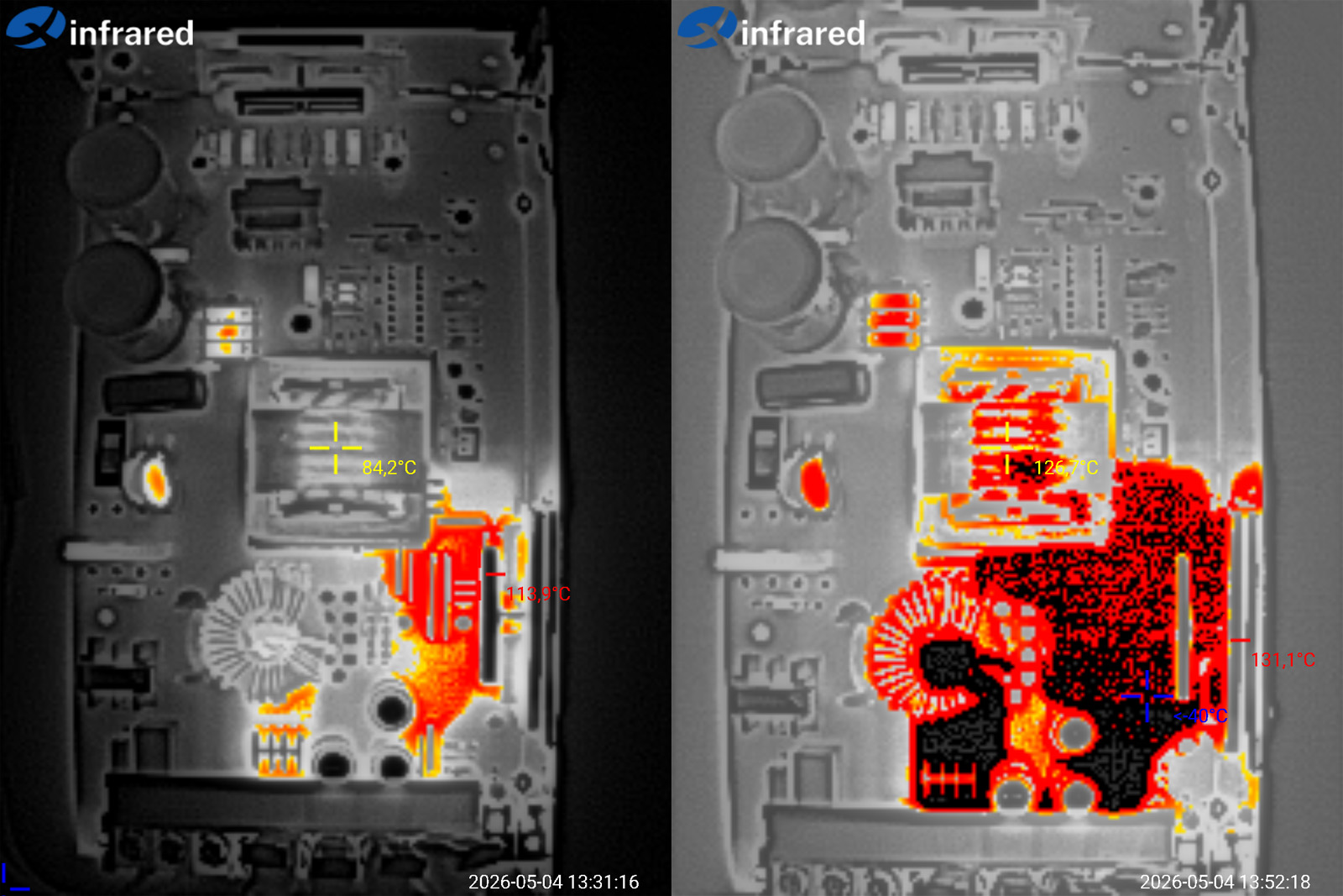
The transformer windings were just over 100 degrees at 10 A, which is normal. But in the screenshot on the right, at the very bottom, you can see a resistor that heats up to over 135 degrees. Apparently it's the snubber resistor, and I would at least use one with a higher power rating.
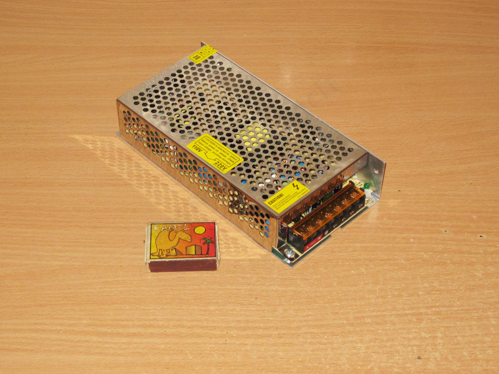
The 100 W model, rated for 20 A.
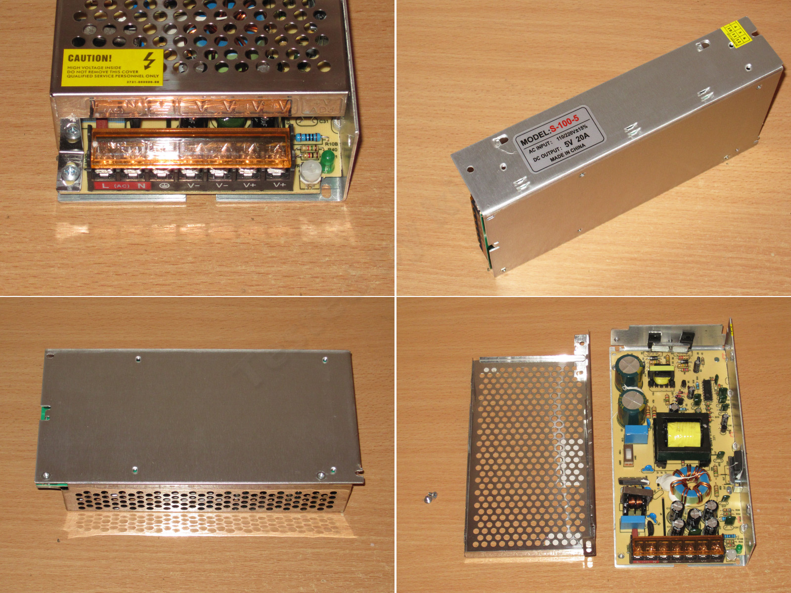
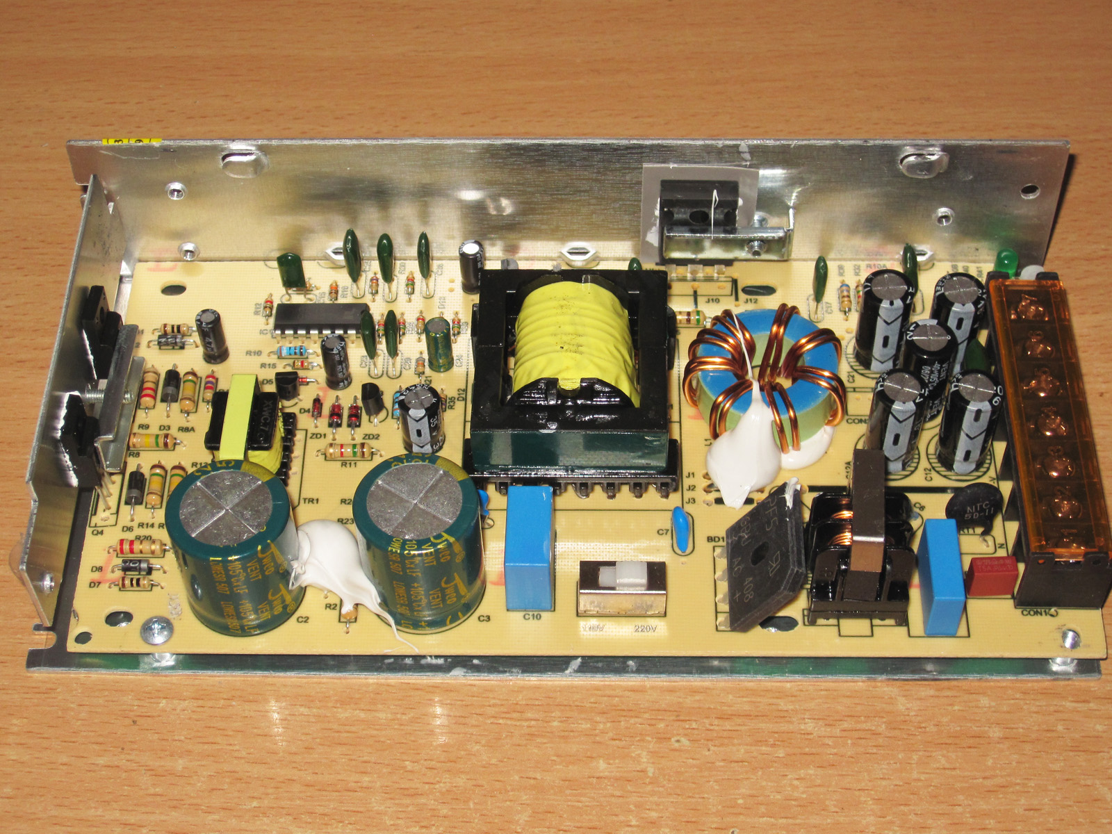
Here we get an even more familiar form factor—pure classic. Dimensions: 199x97x42 mm.
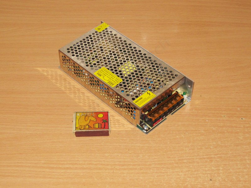
There's not much to comment on here; it's all typical for power supplies like this.
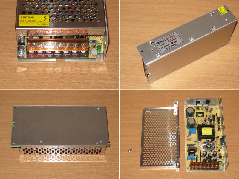
The layout and circuit design are so classic that they make me nostalgic; they immediately bring the early 2000s to mind.
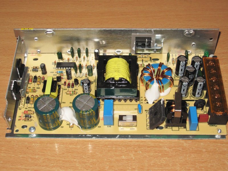
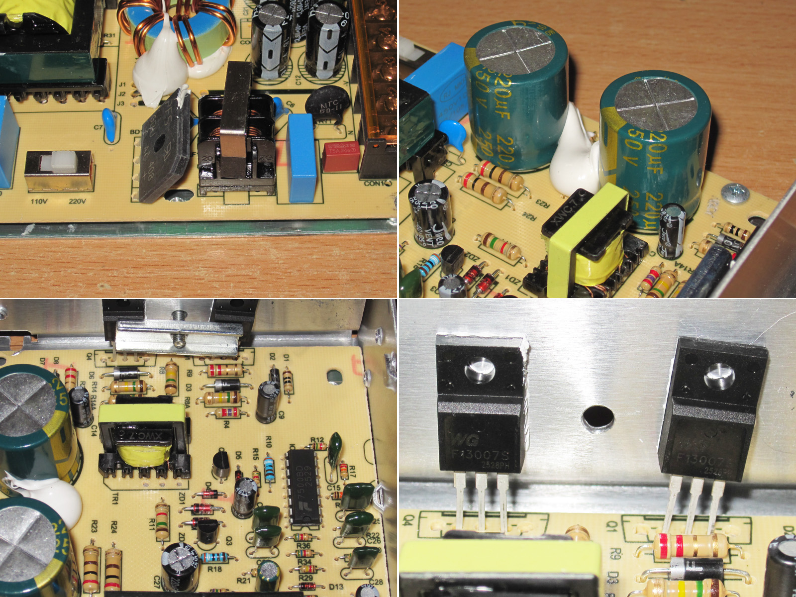
There's an input filter, complete with an inductor, an X capacitor, and a thermistor—in short, all the essentials.
The input capacitors are marked 220 µF, but we'll check that.
The circuit is a familiar design based on the TL494/KA7500 and their many clones.
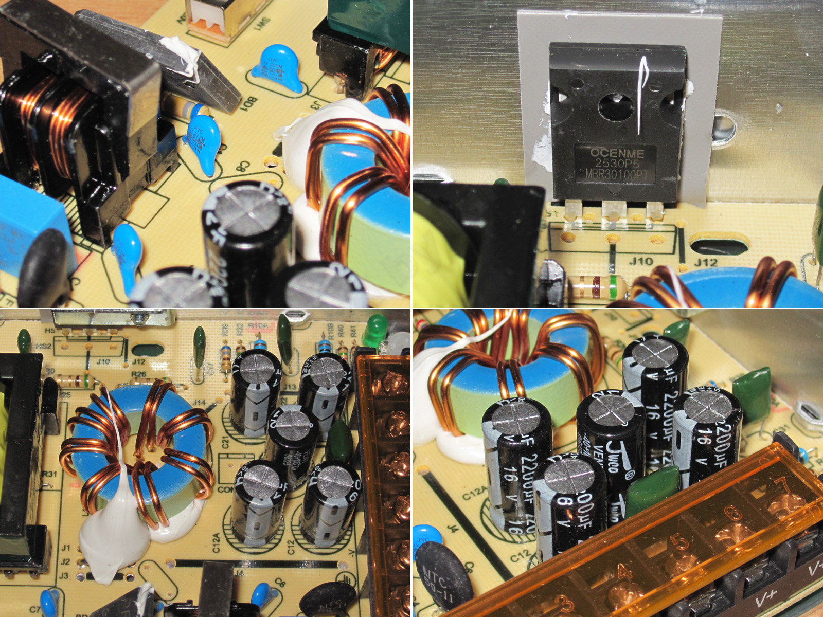
The 13007 transistors are more than adequate for 100 W.
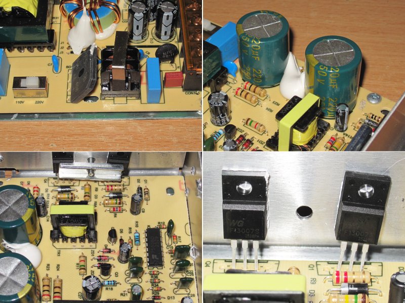
There's also a whole array of Y capacitors, which is a good thing.
The output diode assembly is rated for 30 A and 100 V. I would have used a 40 A, 45 V part instead; it would run cooler.
Because of the topology, there's an output energy-storage inductor, in this case wound on a single powdered-iron core.
The output has five 2200 µF, 16 V capacitors, which is plenty in terms of both capacitance and voltage rating, although 10 V capacitors would have been enough.
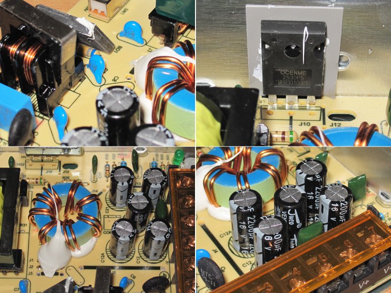
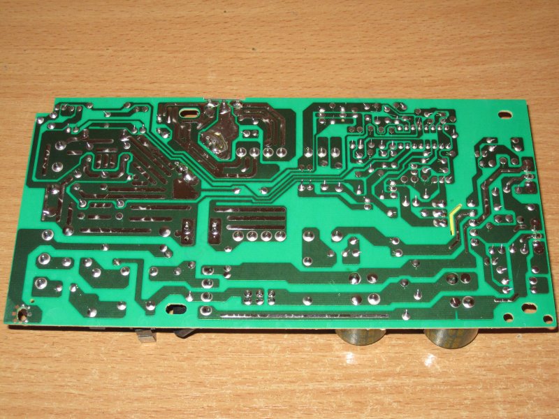
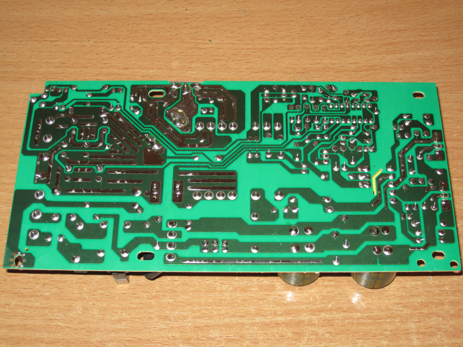
The board is neat and clean; I didn't spot any flaws. It's actually hard to mess this up, but some people still manage it from time to time.
The clearances are adequate here, too, and there's a slot under the galvanic isolation transformer (TGR).
Note that the board has holes aligned with the power supply's mounting holes. That's a thoughtful touch—you won't end up driving a screw into the board.
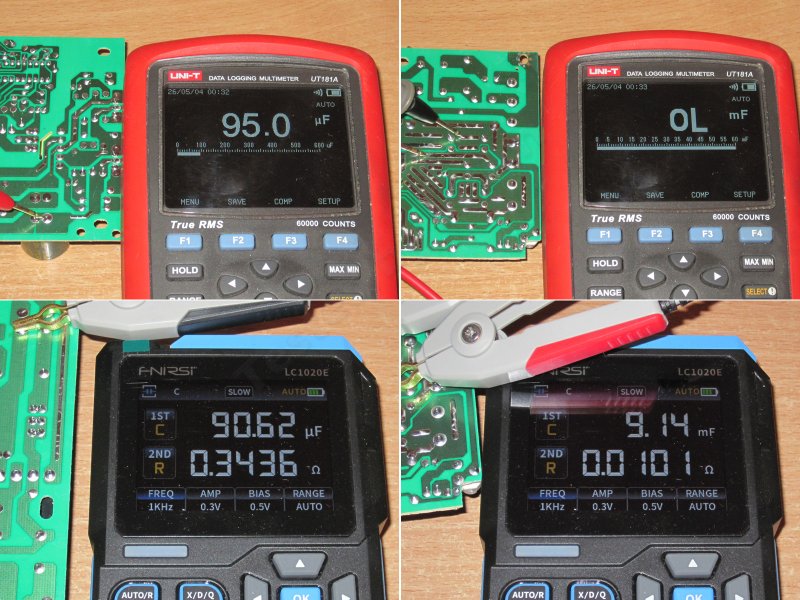
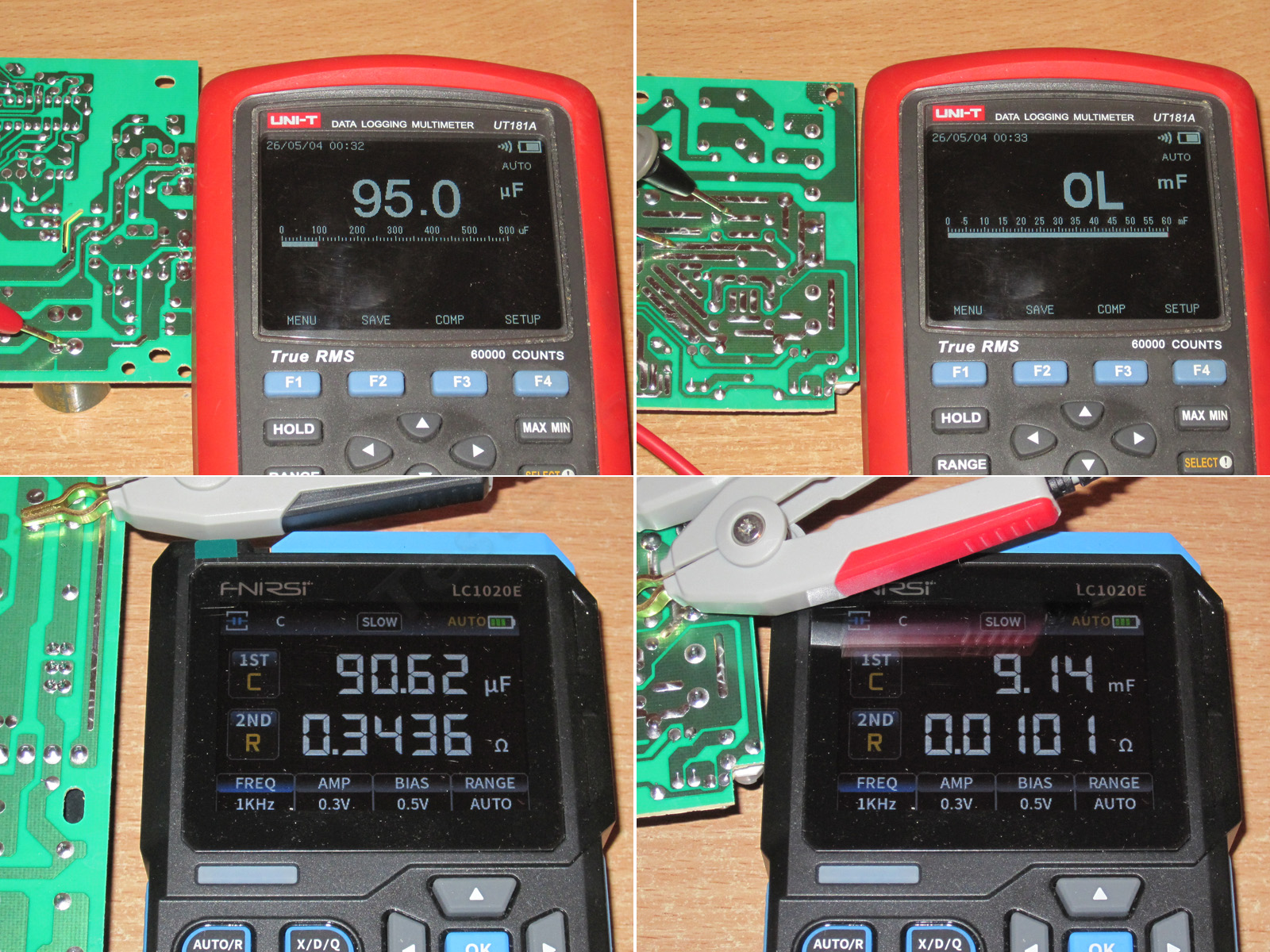
I ran into a problem while measuring capacitance here. The input capacitor was fine: the multimeter read 95 µF. Fnirsi was less optimistic at 90 µF, but that's down to the measurement mode. In any case, the capacitance is close to the stated value (it should be 110 µF) and is normal for a 100 W power supply.
The output capacitors were another story. The multimeter refused to measure them at all, while Fnirsi first gave a much lower reading, and then the readings fluctuated quite a bit. When I disconnected the bias, the reading started jumping all over the place, from zero to 14,000 µF.
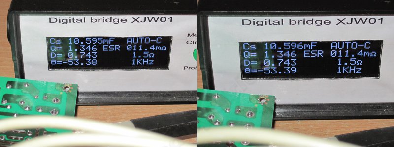
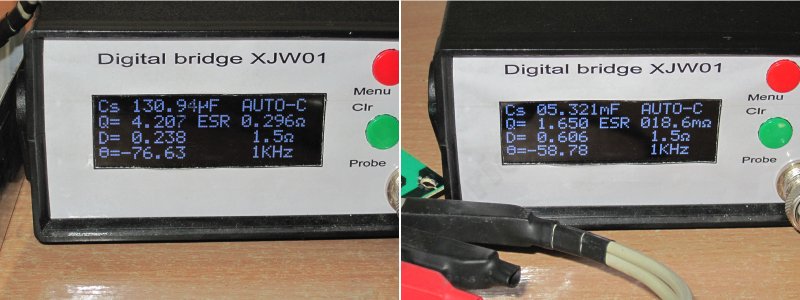
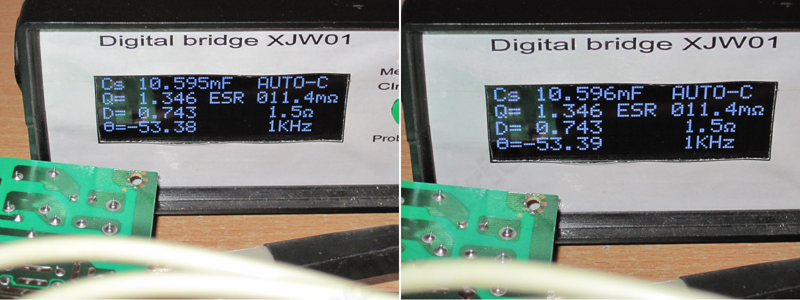
I had to bring out the old XJW01, which showed the youngsters how it's done: 10,600 µF, with the reading staying practically rock-steady. If it fluctuated at all, it was only in the least significant digit. And the measurement result looks realistic, too.
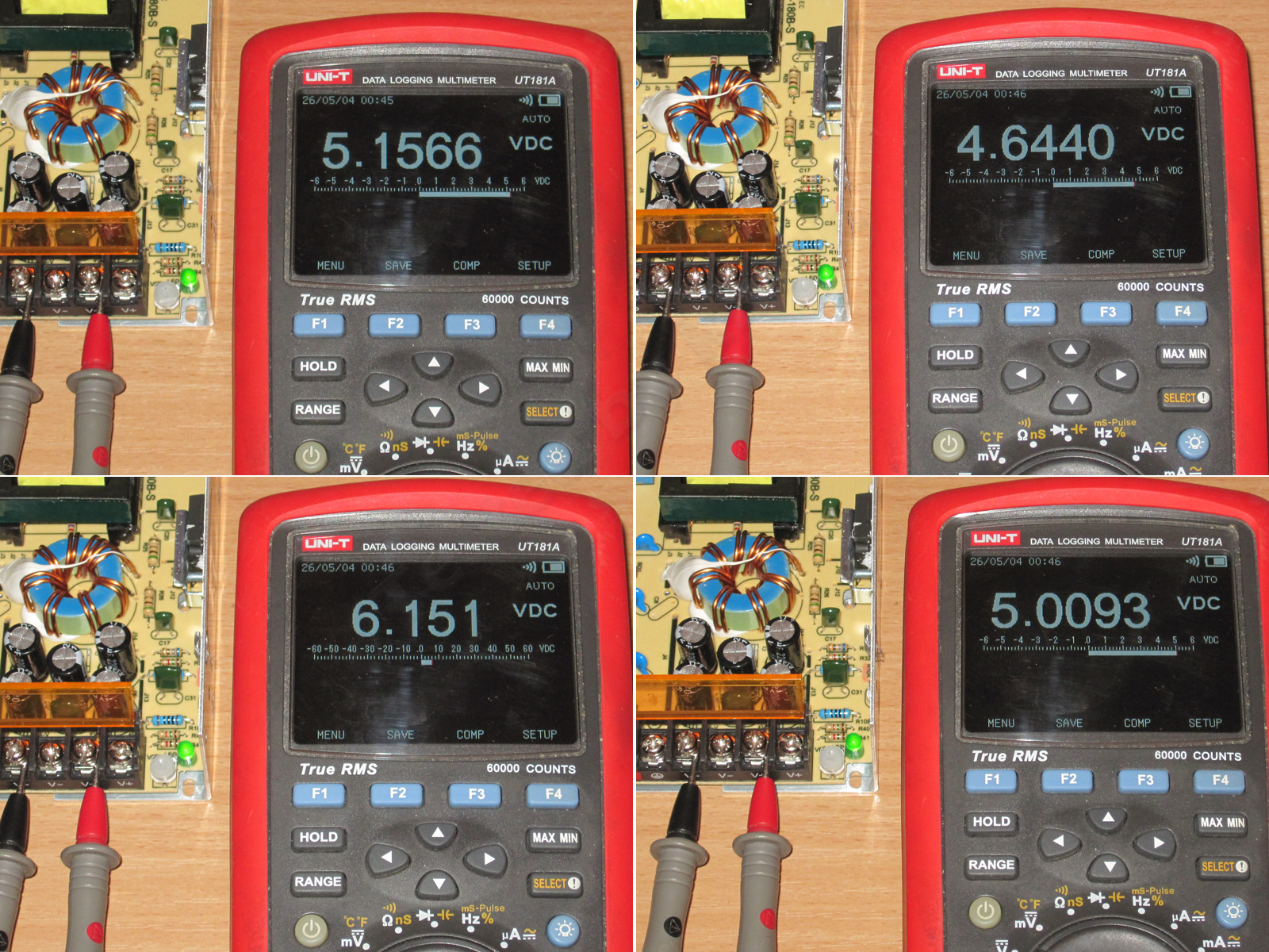
The output was initially 5.16 V. It can be adjusted from 4.64 to 6.15 V; I set it to 5.01 V for the tests. The adjustment is a little coarse.
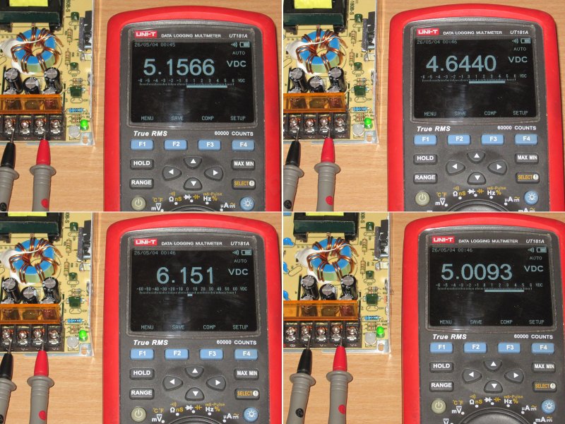
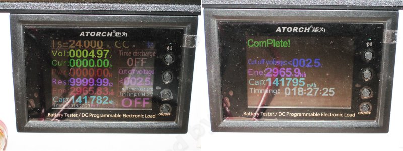
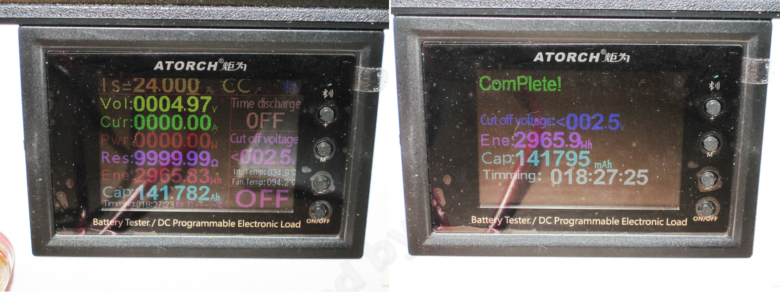
The protection is set to about 24 A, which is perfectly reasonable for a 20 A power supply.
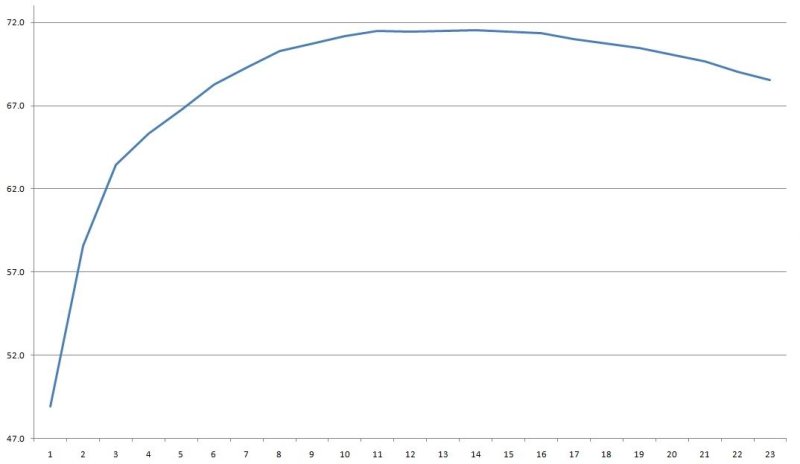
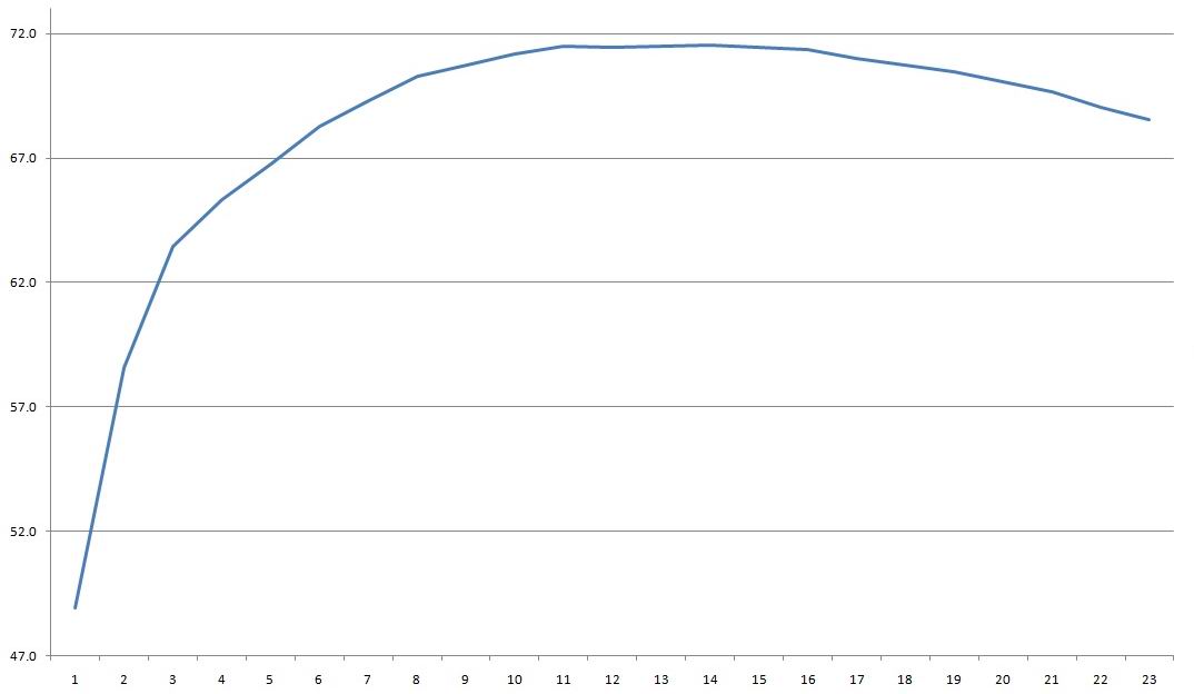
Efficiency from 1 to 23 A, in 1 A increments, came out at about 71–72%, typical for budget models with this topology.
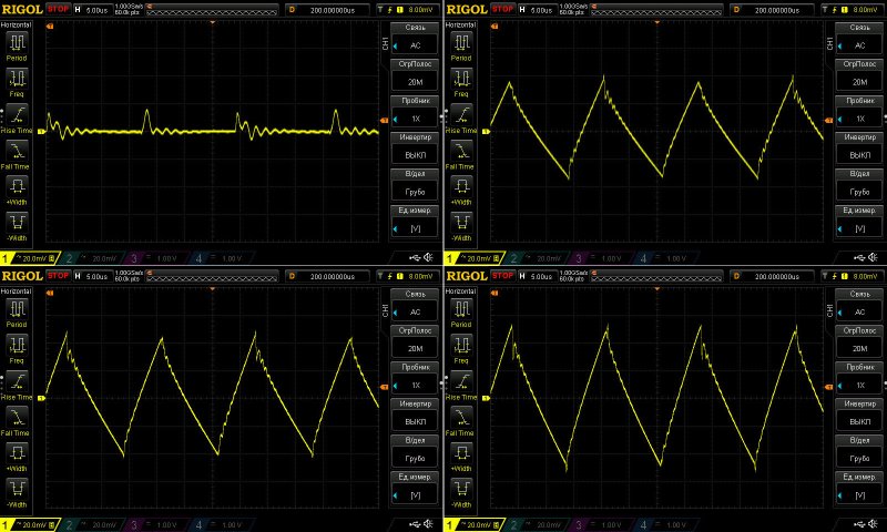
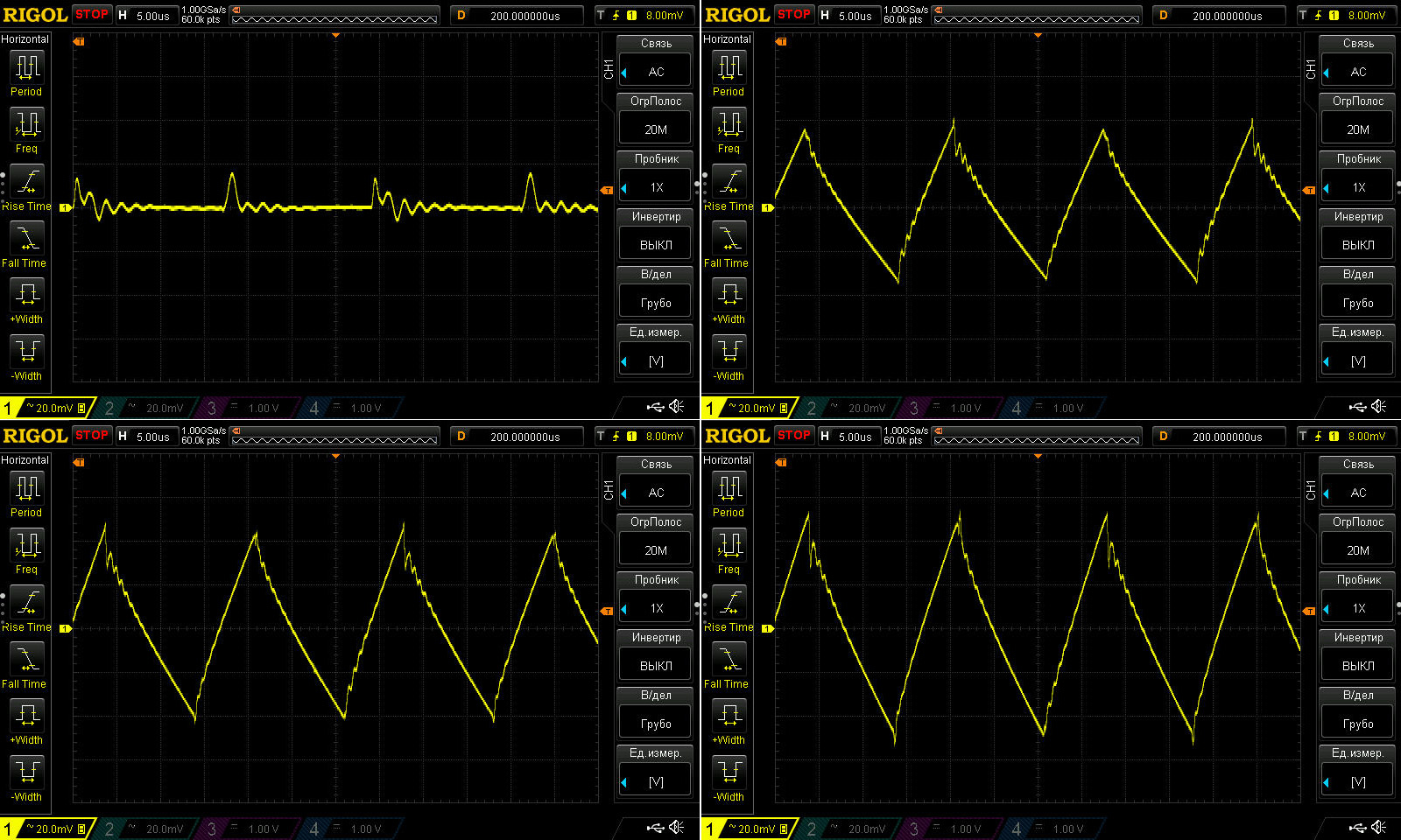
Ripple with no load and at currents of 7, 14, and 21 A.
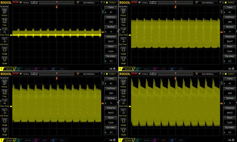
This is quite acceptable overall: 100 mV at the heaviest load. But the ripple doesn't really depend much on the load; at 14 A, it's around 85–90 mV. That's fine considering the fairly high current, and 2% ripple is perfectly normal anyway.
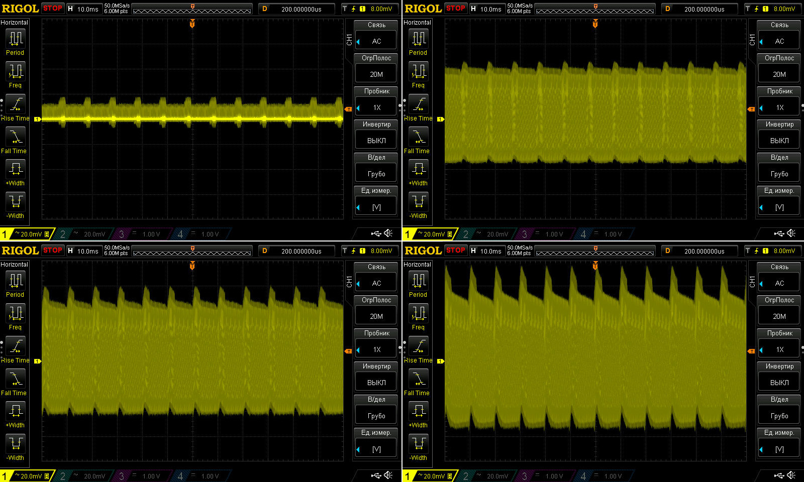
At low frequency and maximum current, peaks at 100 Hz started to become noticeable, but again, everything is within the normal range.
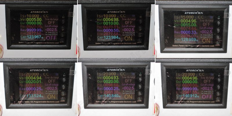
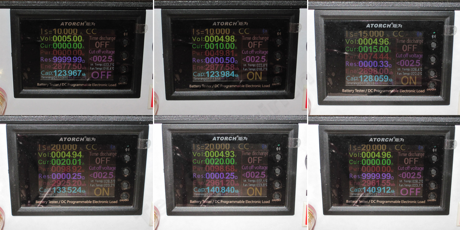
The thermal test was run at currents of 10, 15, and 20 A.
1. Initial no-load voltage: 5 V
2. At 10 A, it sagged slightly to 4.98 V.
3. At 15 A, with the unit already warm, it was 4.96 V
4. At 20 A, once warmed up, it was 4.94 V
5. At 20 A, when hot, it was 4.93 V
6. After removing the load, the voltage rose to 4.96 V.
So, the current causes a drop of about 30–40 mV at 20 A, and temperature causes a drop of about 40 mV. Both effects are negative, but well within the normal range.
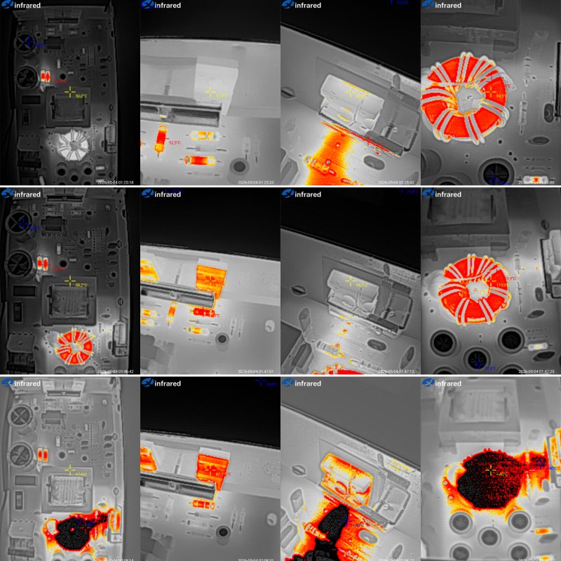
Now for the temperatures.
At 10 A: transformer 50°C, transistors 47.5°C, diode assembly 69°C, and output inductor almost 100°C.
At 15 A: transformer 58°C, transistors 61°C, output diode 94°C, and inductor 120°C. So far, the only concern is the output inductor.
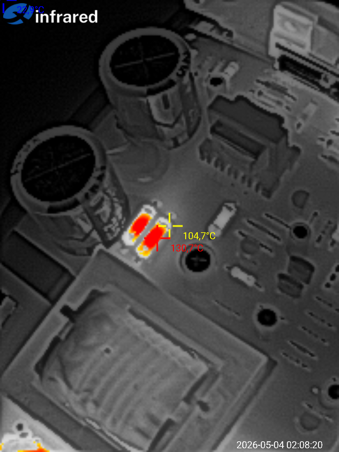
At 20 A: transformer 68°C, transistors 86°C, output diode assembly 120°C. The thermal camera went off the scale on the inductor, so it was definitely above 135°C.
The unit can't handle 20 A; its maximum is 15 A. It would perform better with a more powerful inductor and, at the very least, thermal paste between the diode assembly's heat spreader and the case. Another option is to install a more suitable diode assembly rated for higher current and lower voltage.
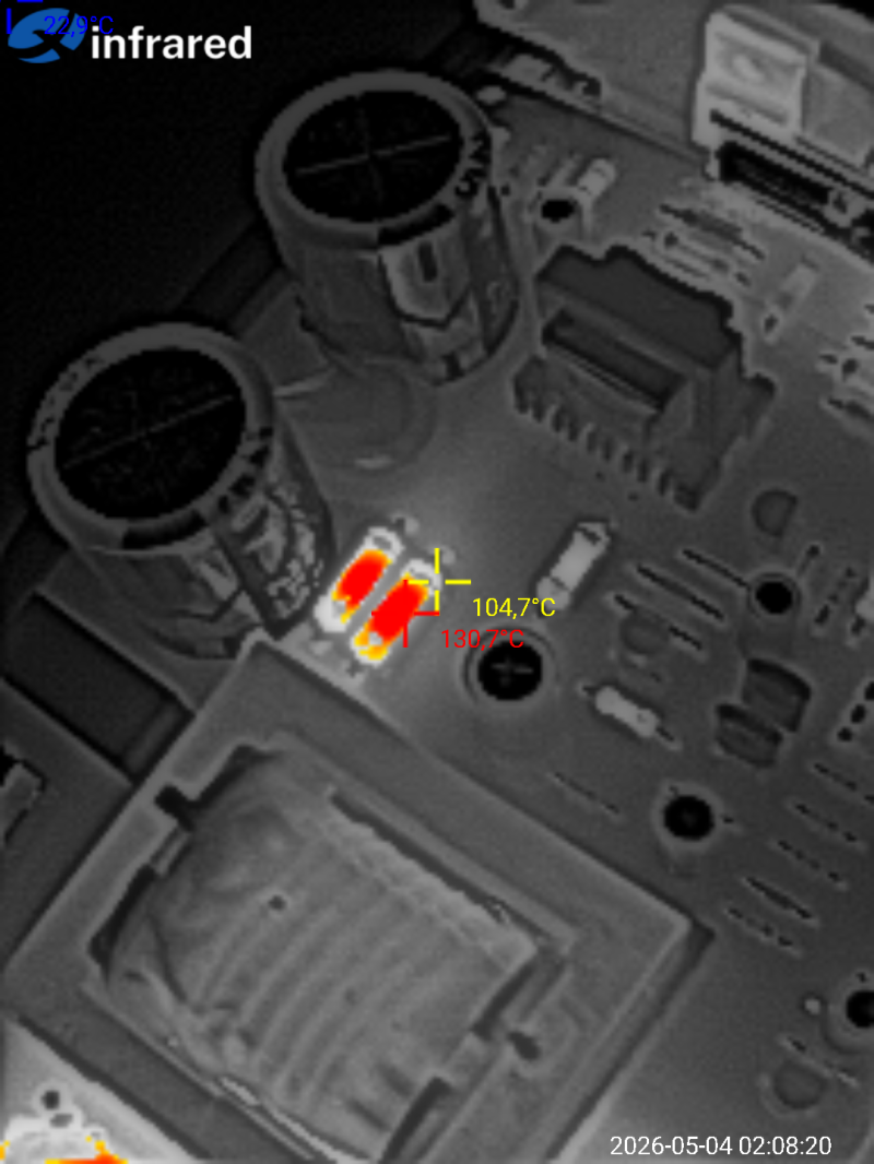
The snubber resistors also got pretty hot, around 131°C, so it would be better to use higher-power ones.
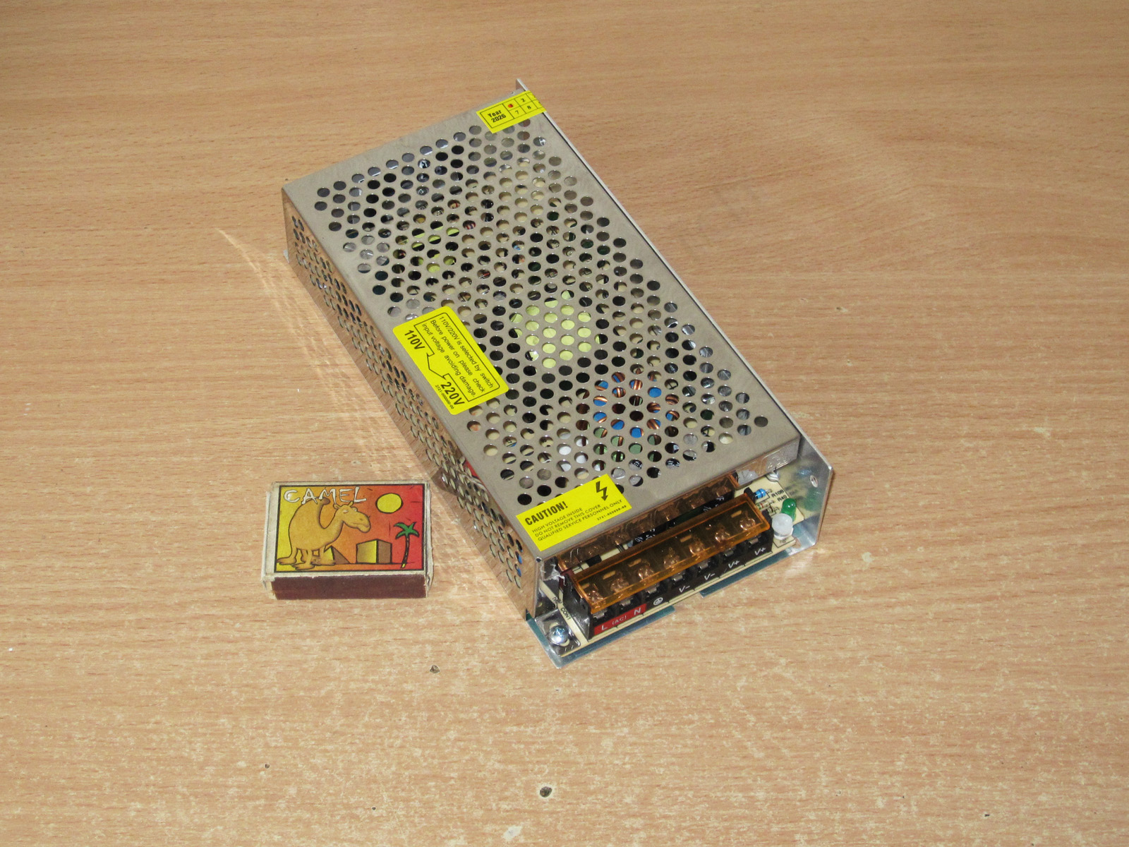
Next model: 150 W, 30 A.
It's the same size as the previous one: 199 × 97 × 42 mm
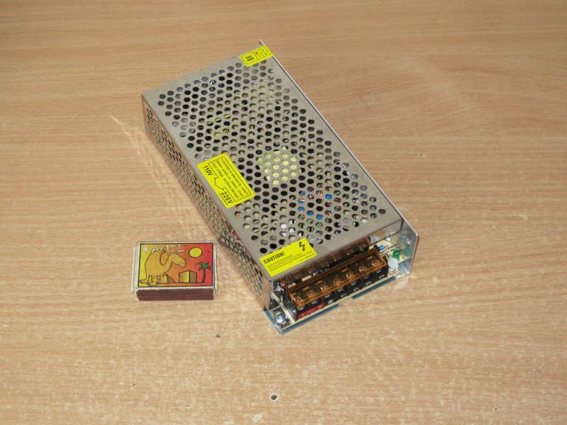
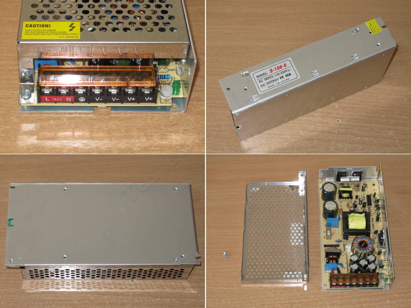
The design is identical to the previous model.
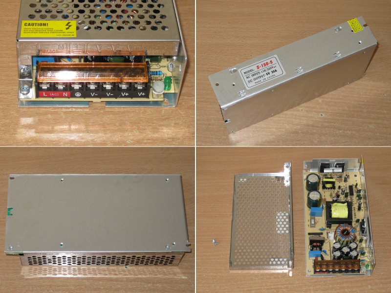
In fact, this is the same model as before, scaled up for higher power by replacing some components. The 100 W version is on the left, the 150 W one on the right, while the board itself is marked 180 W. This is perfectly normal practice; it lets you adjust the price a bit if you don't need the higher power.
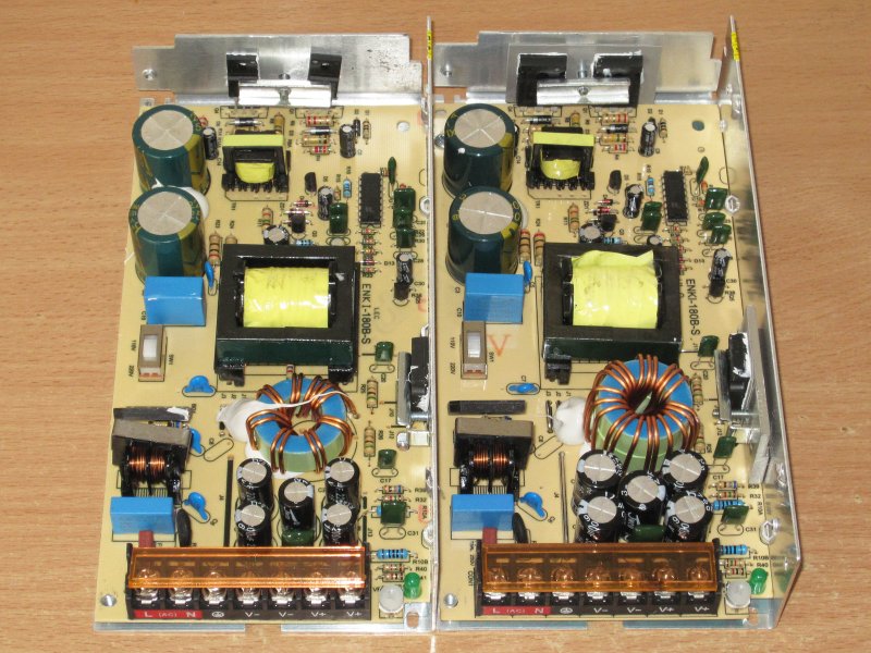
There are a few changes, which I'll list below.
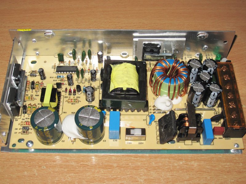
1. The bridge rectifier and input filter are identical
2. The input capacitors are also unchanged, although in this case they would usually use higher-capacitance ones.
3. The transistors have been replaced; these are 13009s now. Damn, I typed their type automatically :)
4. The output diode assembly is rated for 40 A and 45 V. This is what the previous model should have had, and this one could really use two.
5. The inductor is wound on two cores, and the winding now uses three wires instead of two.
6. There are still 5 output capacitors, as before, and they're still rated for 16 V, but now they're 3300 µF.
So far, we can see that almost all the necessary changes have been made, in line with the increase in power.
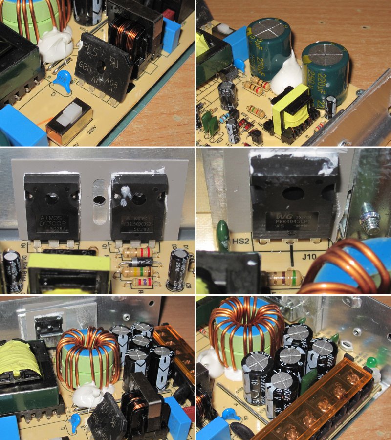
Since the output current is 1.5 times higher, they installed three shunts instead of two. In other words, each shunt corresponds to roughly 11–12 A of output current. Where the previous model had 23–24 A, we can expect around 34–35 A here.
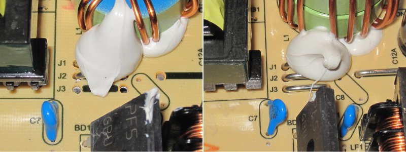
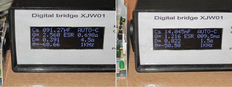
I had trouble measuring capacitance, most likely because of the output ballast resistance, which is usually low at 5 V. So from here on, I took measurements with my old LCR meter.
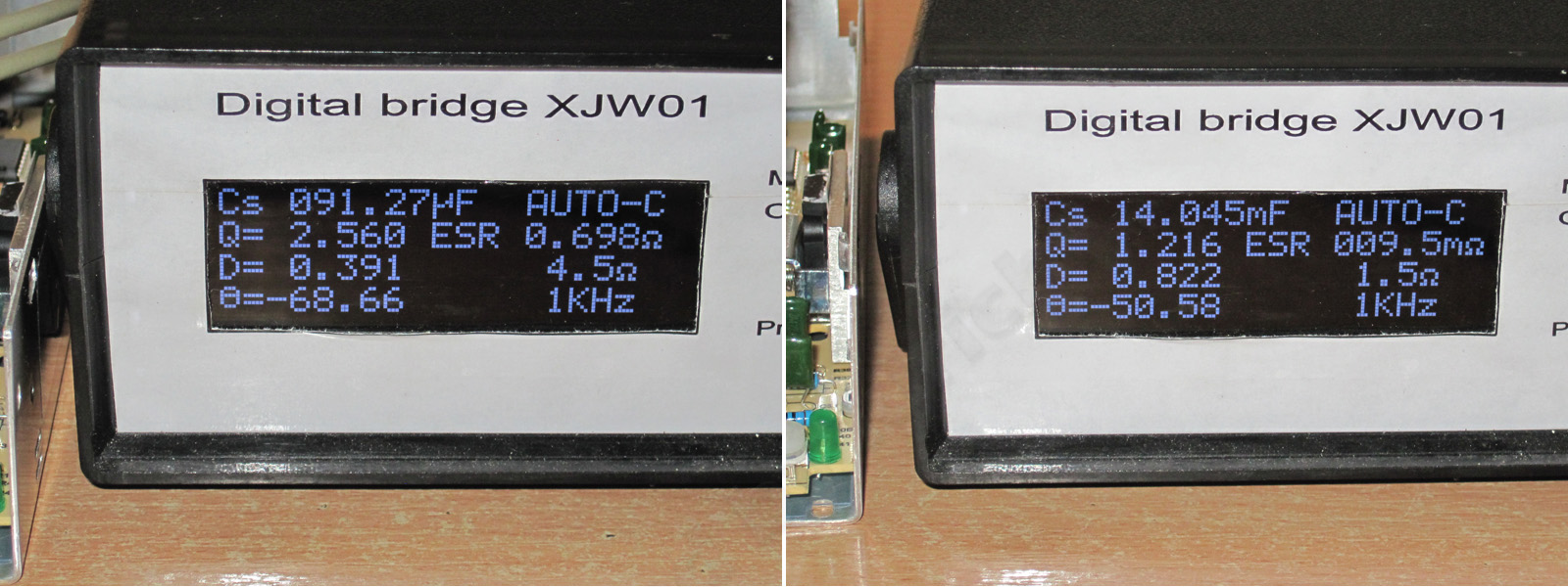
The input capacitance is 91 µF, as before; the output is about 14,000 µF, which is close to the stated value. The ESR is a little high because I measured it at the terminals rather than directly on the board.
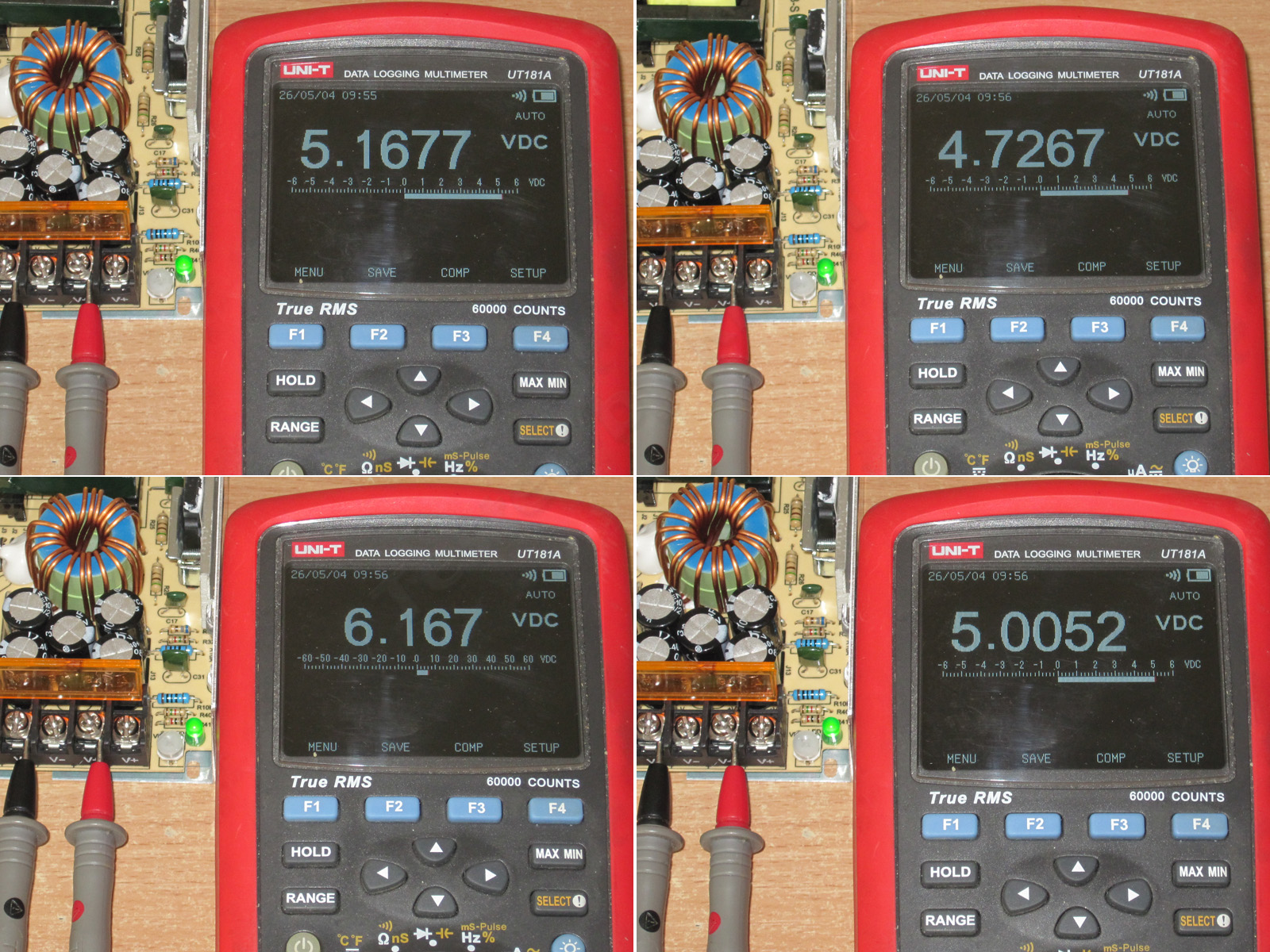
The output was 5.16 V, adjustable from 4.72 to 6.17 V. I set it to about 5 V.
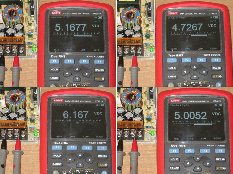
I checked the protection while measuring efficiency. The power supply shuts down at around 34 A, just as I expected.
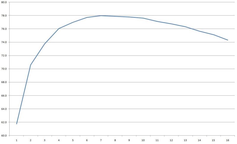
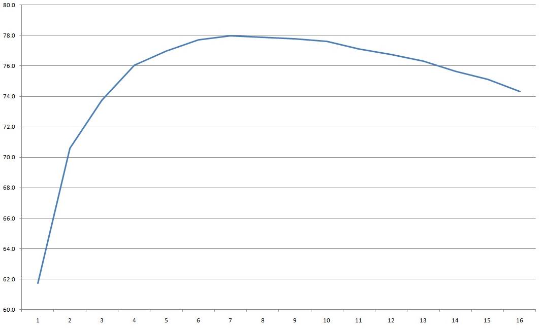
I measured efficiency from 1 to 33 A in 2 A increments, with the final step in 1 A increments.
I got around 76–78%, which is typical for power supplies like this.
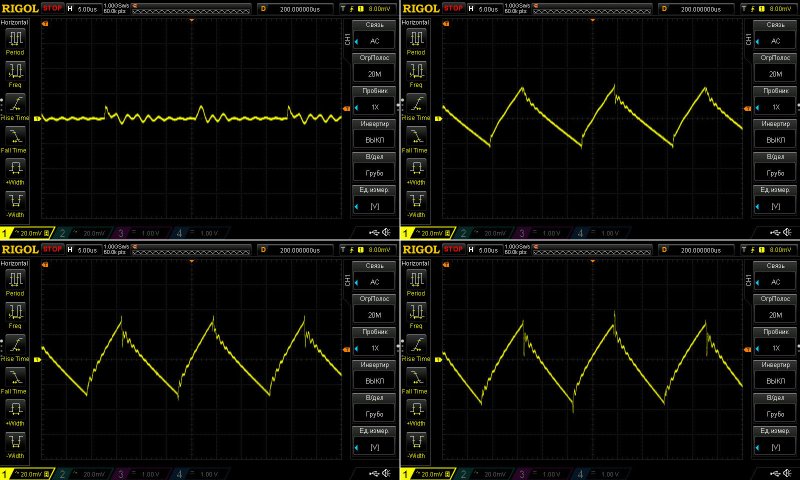
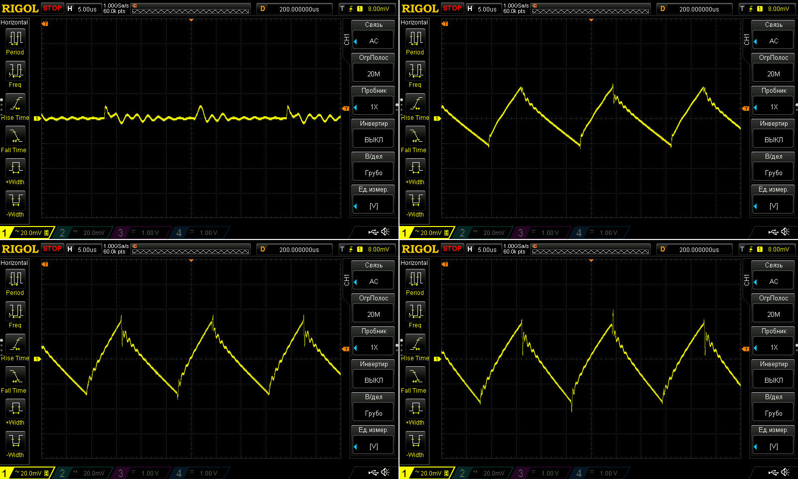
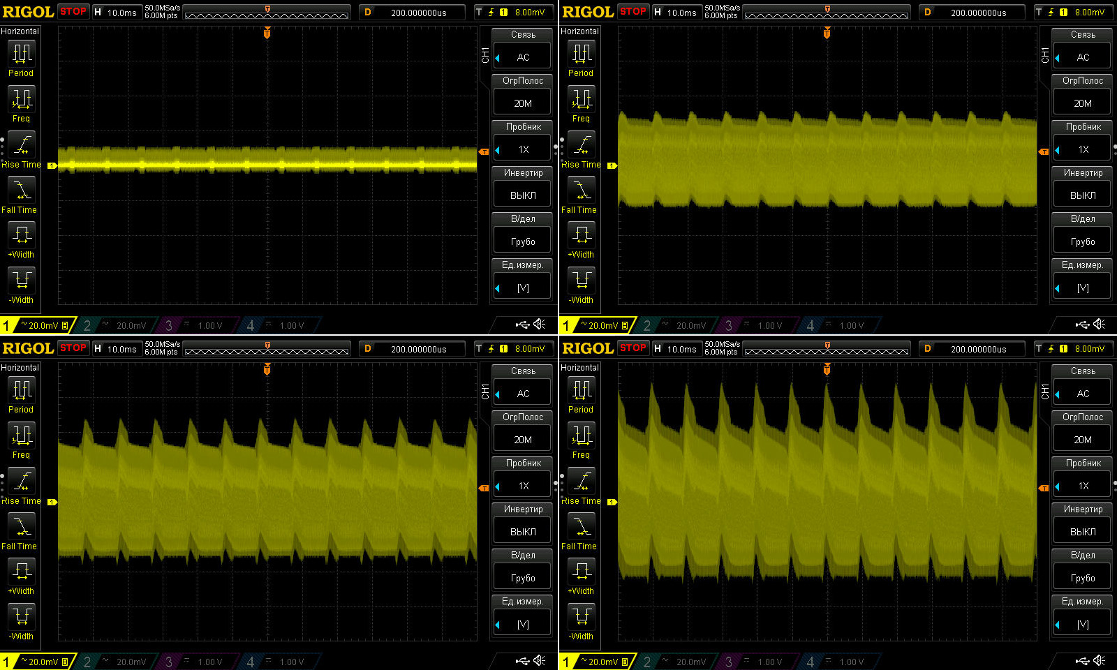
Ripple was measured with no load and at currents of 10, 20, and 30 A.
At maximum current, it was around 65–70 mV, which is actually very good and definitely better than the previous model, which had around 90–100 mV.
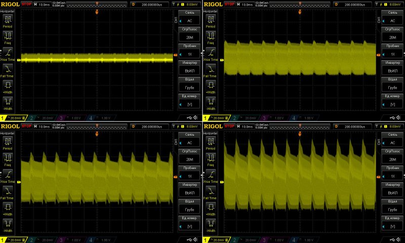
At 100 Hz, the ripple is noticeably higher. The input capacitors are the same as before, after all. Still, I think it's perfectly acceptable, especially since these power supplies are unlikely to be used for audio equipment.
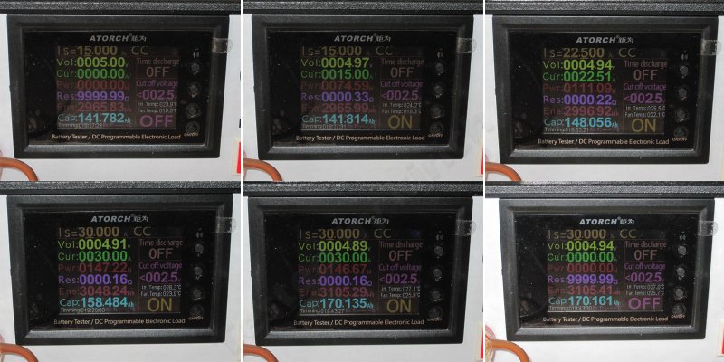
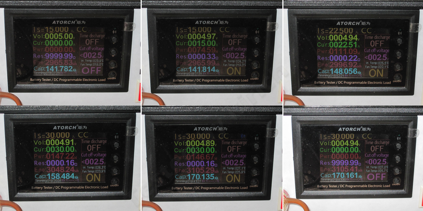
The load test was performed in three modes: 15, 22.5, and 40 A, i.e. 50%, 75%, and 100% load.
1. With no load, the voltage is exactly 5 V
2. At 15 A, it dropped to 4.97 V, much like the previous model.
3. At 22.5 A, with the power supply warm, we get 4.94 V
4. At 40 A, once it had warmed up, I got 4.91 V
5. At the same 40 A, but now hot, we get 4.89 V
6. After removing the load, the voltage rose to 4.94 V.
Here, the effect of current and warm-up is a little greater. I'd even say it scales with the increase in power: 60 mV from heating and 50 mV from the load. But that's perfectly normal; you can simply set the voltage a little higher to begin with, which is what I did here.
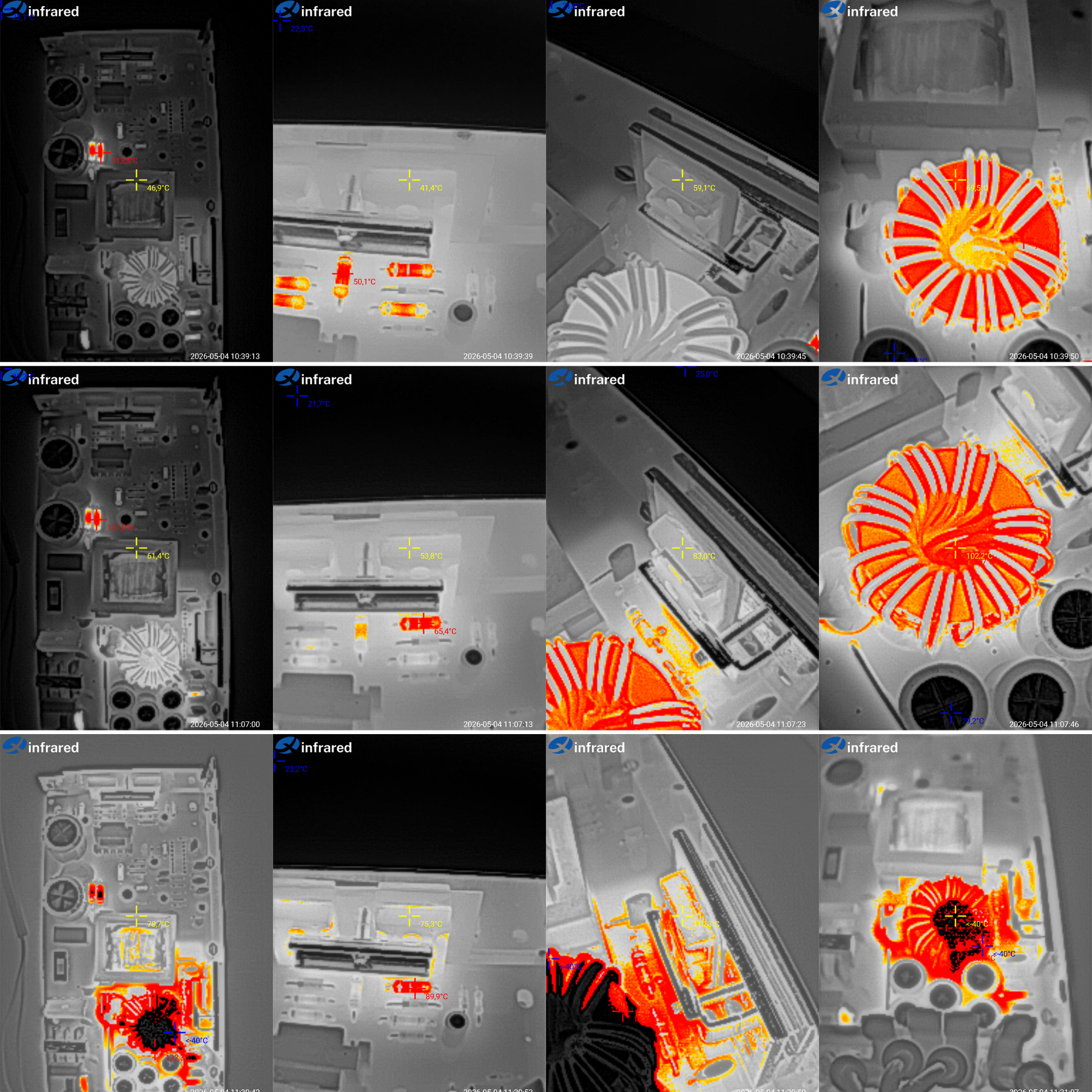
Temperatures.
15 A — transformer 47 degrees, transistors 41 degrees, diode assembly 59 degrees, inductor around 70 degrees.
22.5 A — transformer 61.5 degrees, transistors 54, diode assembly 83, inductor 102 degrees.
40 A — transformer 79, transistors 75, diode assembly 110, inductor over 135 degrees.
The picture is similar to the previous model: the power supply handles 75% power just fine, but overheats at 100%. And once again, the same components are the problem: the diode assembly and the inductor. Basically, I would at least rewind the inductor with thicker wire or more strands and, as I mentioned earlier, install two diode assemblies instead of one.
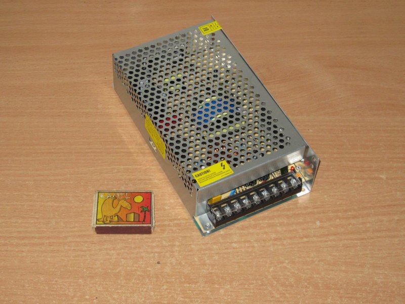
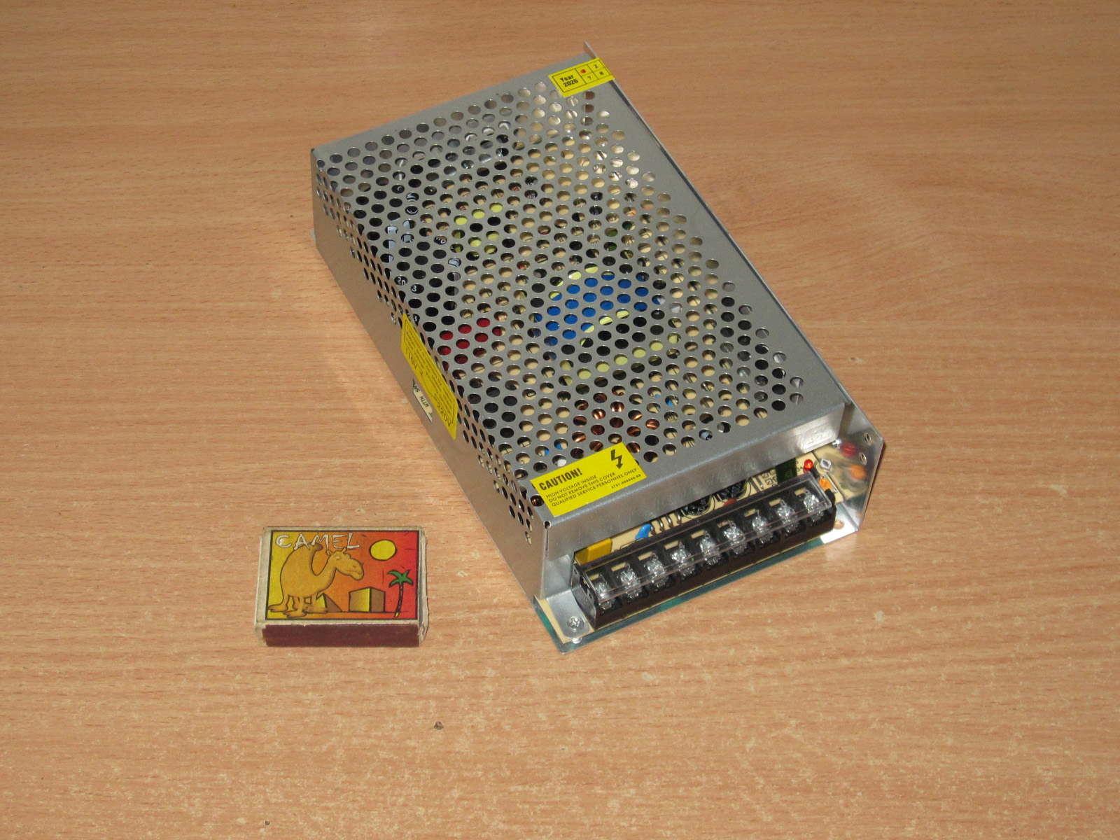
And now the two most powerful power supplies in this lineup: 200 W, 40 A.
Dimensions: 197 × 109 × 50 mm.
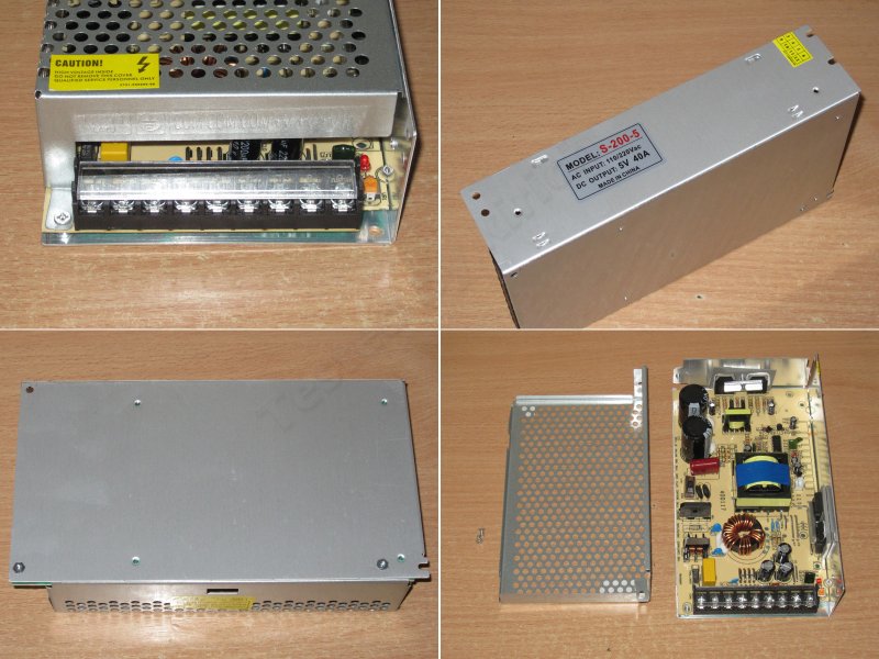
There are two versions, with passive and active cooling. I'll start with the first one.
In terms of design, this is the same power supply as the previous models, just a little larger.
The layout is the same, but there are a few changes. The first thing that catches the eye is that there are two input thermistors, while the output has surprisingly few capacitors.
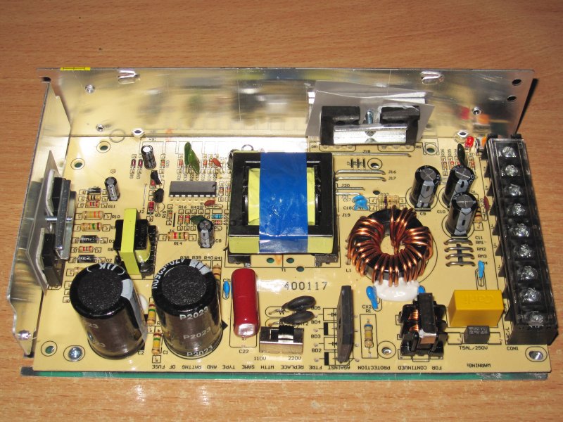
The input capacitors are rated at 470 µF, or 235 µF when connected in series.
The “hot” side is practically identical to the previous models, especially the 150 W version.
The transistors are the same as in the 150 W model: 13009.
There are now two diode assemblies, each rated for 30 A and 45 V.
The output storage inductor is wound with four strands on what is most likely a sendust core. This is more efficient, which is why it uses a single core.
There are three 2,200 µF, 10 V output capacitors. That seems like rather little capacitance for a 40 A output current, in my opinion.
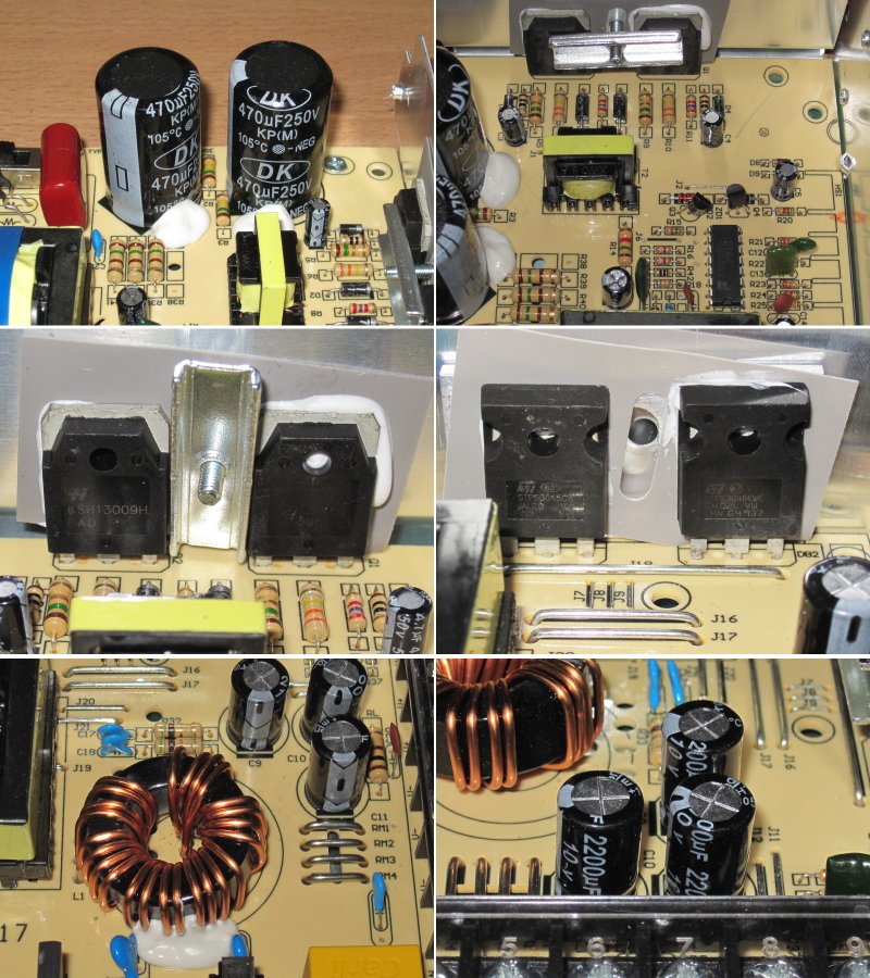
There are four current-sense resistors, in proportion to the increase in current compared with the previous models.
It's interesting that this power supply is so standardized that they even populated the fan power circuit. By the way, you can see the heatsink marking on the board nearby. In my opinion, a heatsink really wouldn't have been out of place here, especially with passive cooling.
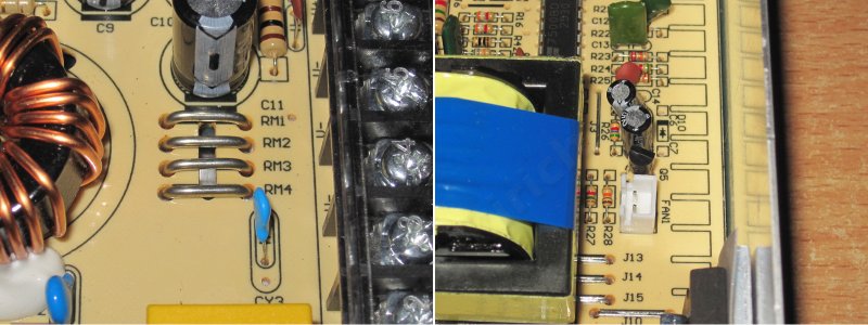
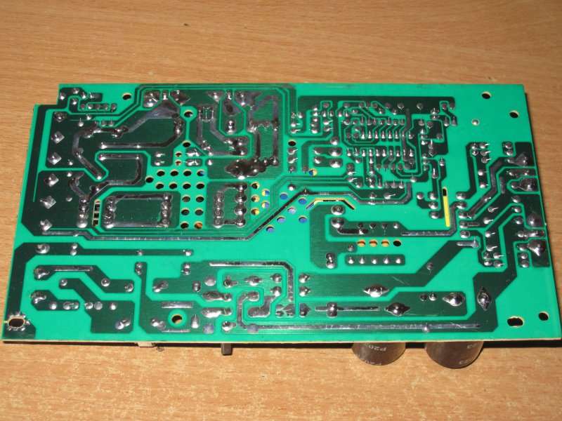
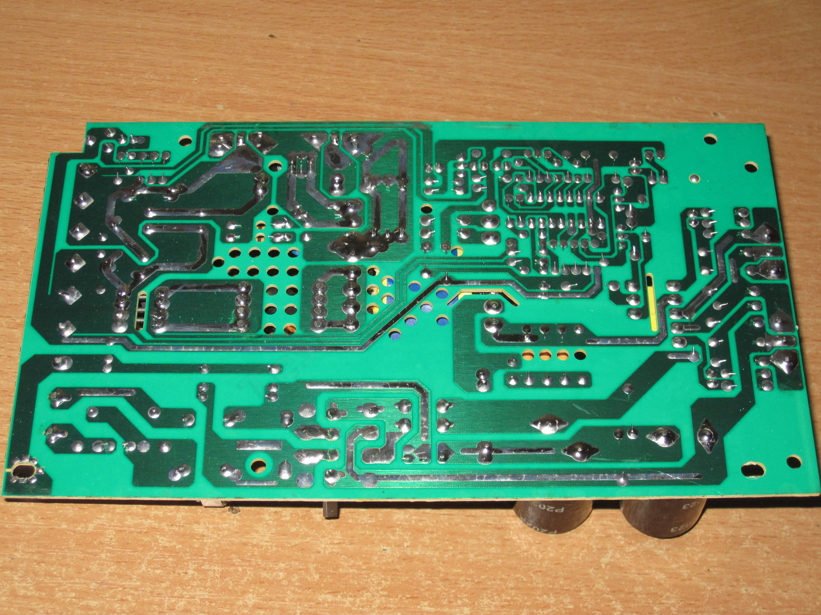
The board has the necessary clearances and slots, but the routing leaves something to be desired: the traces to the capacitors are narrow, which usually has a negative effect on output ripple and radio interference.
The trace width is especially critical here because, although the power supply is only 200 W, it handles 40 A.
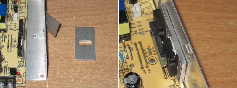
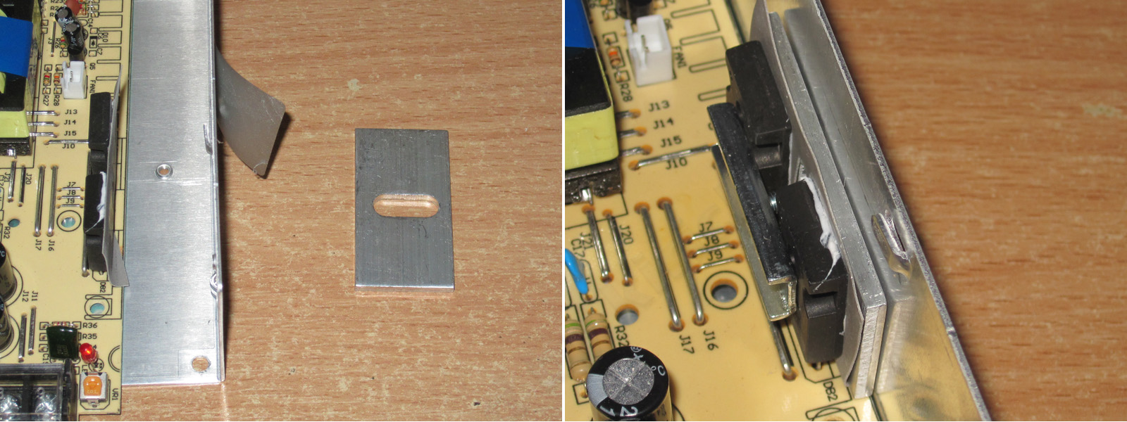
But the traces are a minor issue compared with the heat-spreading plate. First, it has no thermal paste. Second, although I put it back in exactly the same position after taking it apart, there was still a noticeable gap between the case and the plate.
I've written more than once that this is a bad design, both literally and figuratively. There's a very good chance the surfaces won't make proper contact, so heat won't be transferred effectively. The plate should be secured with at least two screws, it should be flat, and there should be thermal paste between it and the case.
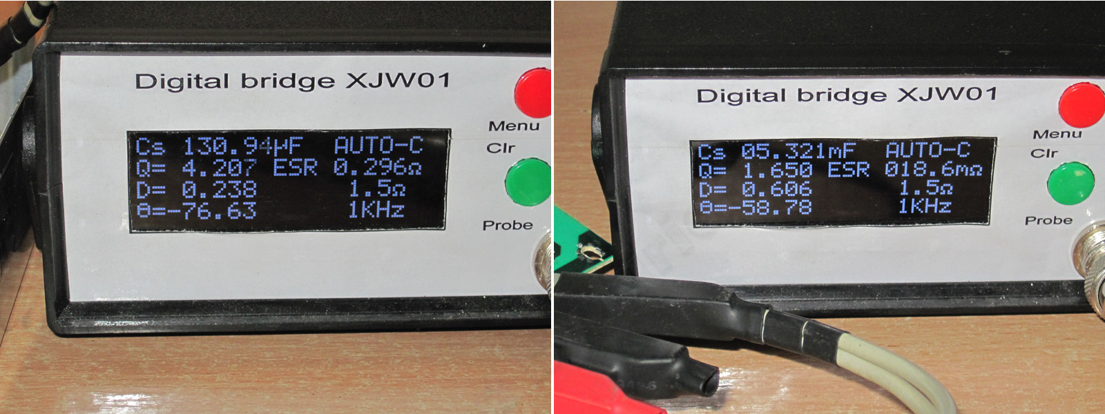
The input filter capacitance is 130 µF, versus the claimed 235 µF. Looks like these are counterfeit capacitors.
The output capacitance is also a little below spec, but not critically so. The ESR, though, is 18 mΩ, which is clearly too high for a current of 40 A.
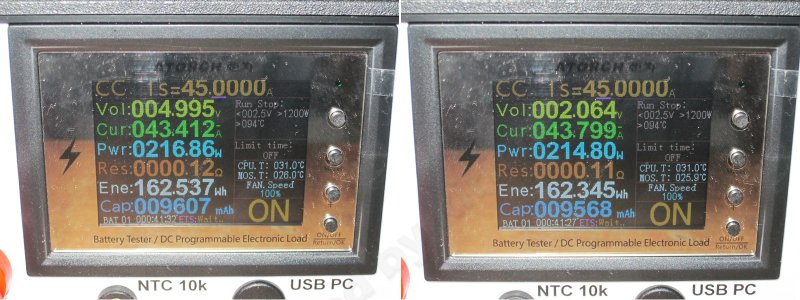
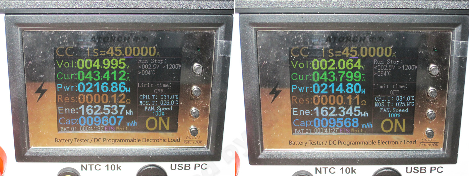
The protection trips at around 43.5 A. That's a little below the calculated value based on the number of shunts, but that's perfectly normal: the scaling doesn't always increase in exact multiples as you add shunts.
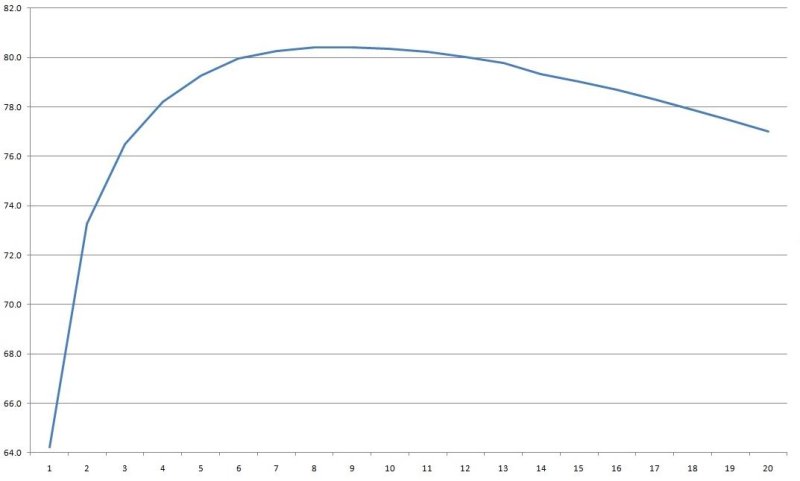
Efficiency from 2 to 40 A, in 2 A increments. Here I even got over 80%, though only over a narrow range. Still, the output inductor's core type deserves a lot of the credit, as does using two output diodes instead of one.
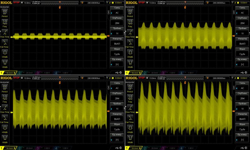
Ripple with no load and at currents of 13, 26, and 40 A.
Well, yes, it's a bit high: 150–170 mV at 40 A. But that was expected, since the output filter's ESR is quite high. I also didn't like the ugly comb-like pattern on the waveforms. Some of that may be due to slightly sloppy PCB routing, but of course I'm not going to check :)
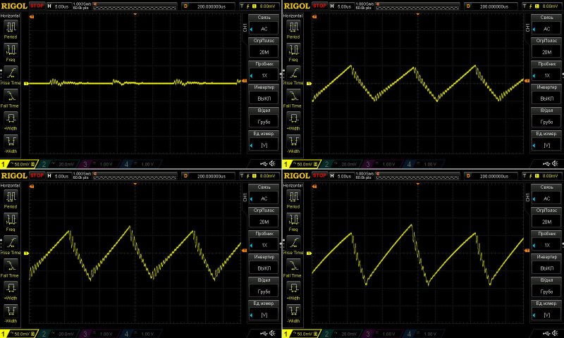
At 100 Hz, the waveform looks pretty unpleasant: there's a lot of ripple at this frequency, and it looks quite ugly.
No, it doesn't usually have much of an effect, but it's still unpleasant. This is probably partly due to the input filter's lower-than-specified capacitance, which may also shorten the capacitors' service life, and partly due to the low capacitance of the output capacitors, the PCB routing, and other parameters of the components themselves.
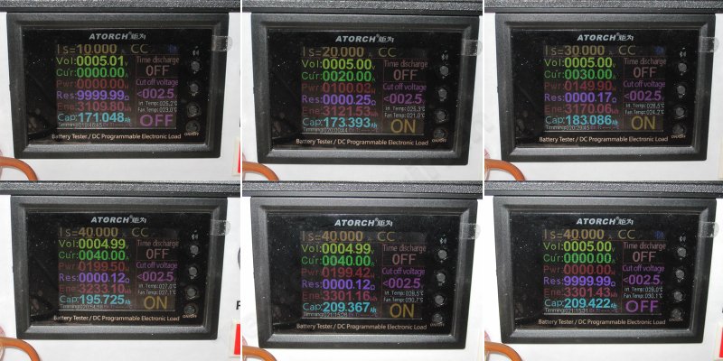
The load test originally went 10-20-30-40 A, but I left the 10 A result out of the photo because it was just a check to see whether the thermal contact of the output diode assemblies was acceptable or needed reworking.
1. No load: 5.1 V
2. At 20 A: exactly volts
3. At 30 A, with the power supply warm: the same 5 V
4. At 40 A, with the power supply already warmed up, there's a slight drop to 4.99 V.
5. Hot, at 40 A: still 4.99 V
6. After removing the load, it's back to 5 V.
Overall, voltage regulation is excellent. The voltage varies by just 10 mV with current, and even then only at the maximum load. A solid 5 out of 5 here.
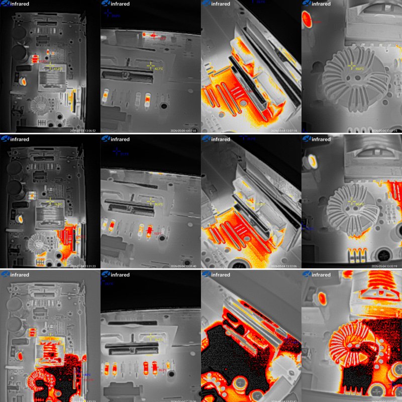
And now, component temperatures in different operating modes.
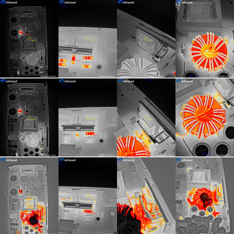
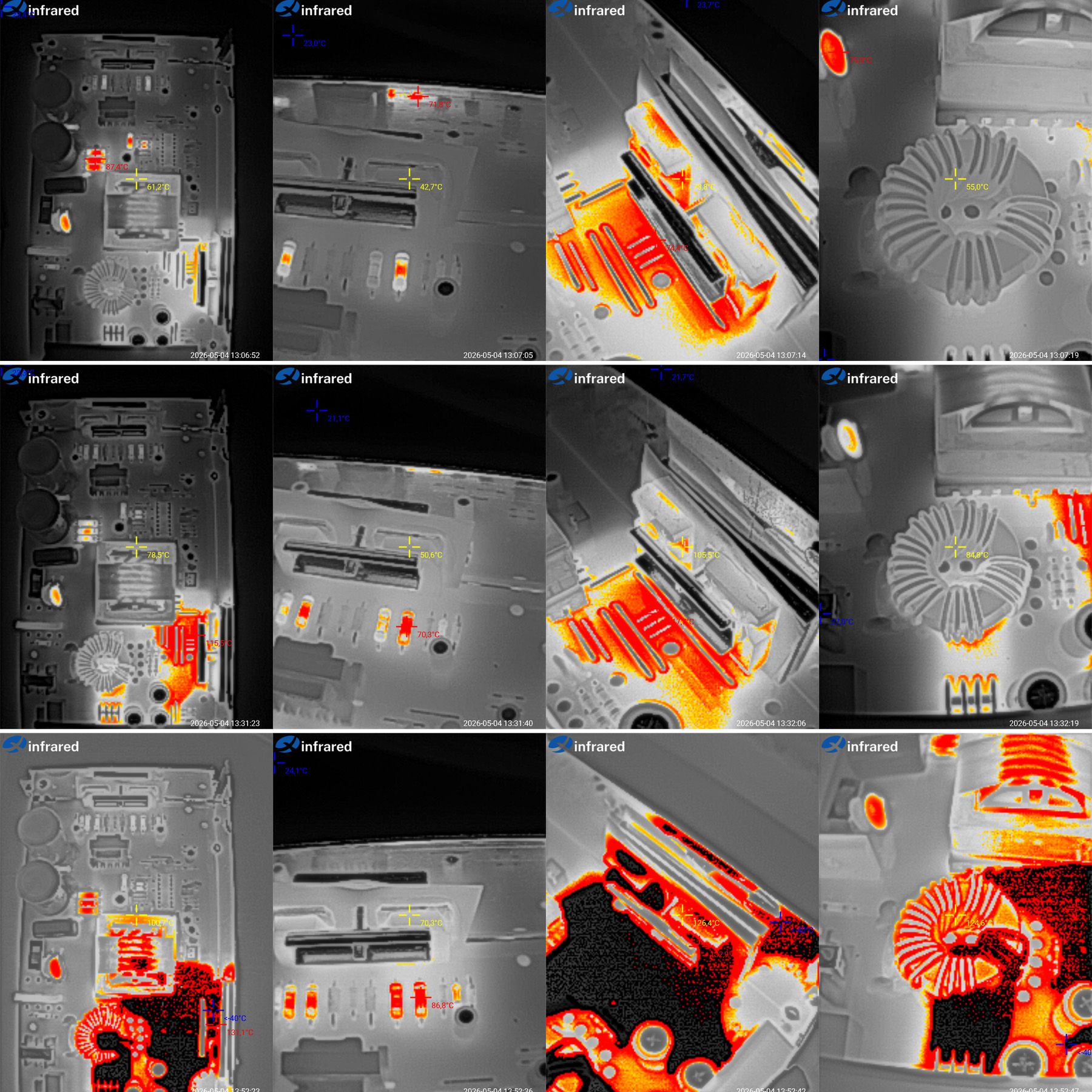
20 A — transformer 61 °C, transistors 43 °C, diodes 74 °C, inductor 55 °C. Almost perfect, if not for the diodes.
30 A — transformer 79 °C, transistors 51 °C, diodes 105 °C, and inductor 85 °C. Once again, the diode assemblies run hotter than the other components.
40 A — transformer 101 °C, transistors 70 °C, diode assemblies 126 °C, inductor 125 °C.
So once again, we have a power supply whose long-term maximum is 75% of its rated output. At maximum current, only the transistors stay at a reasonable temperature. Everything else overheats: the transformer, diodes, inductor, even the circuit board, which gets hotter than 135 degrees. The last part was predictable, as I mentioned.
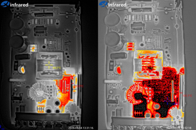
 .
The winding temperature rises sharply with current. At 30 A, everything is fine at 84 degrees, but at 40 A it shoots up to a crazy 127 degrees. Inside the winding, it must be even hotter.
So, the problem with the poor heat-spreading plate was effectively overshadowed by the overheating of other components.
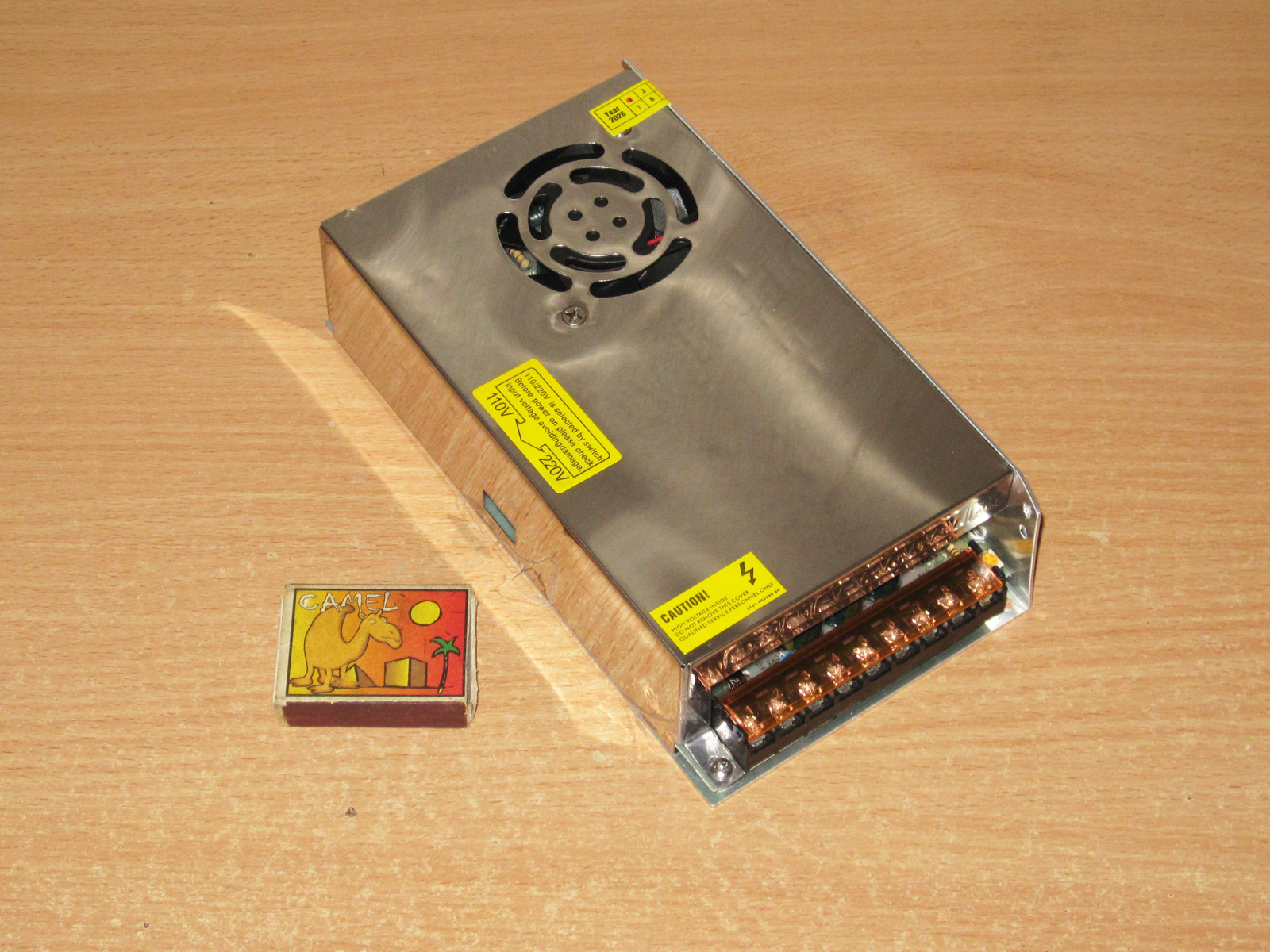
And the last power supply for today: the same 200 W, 40 A, but with active cooling.
The dimensions are the same: 197×109×50 mm.
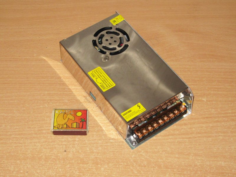
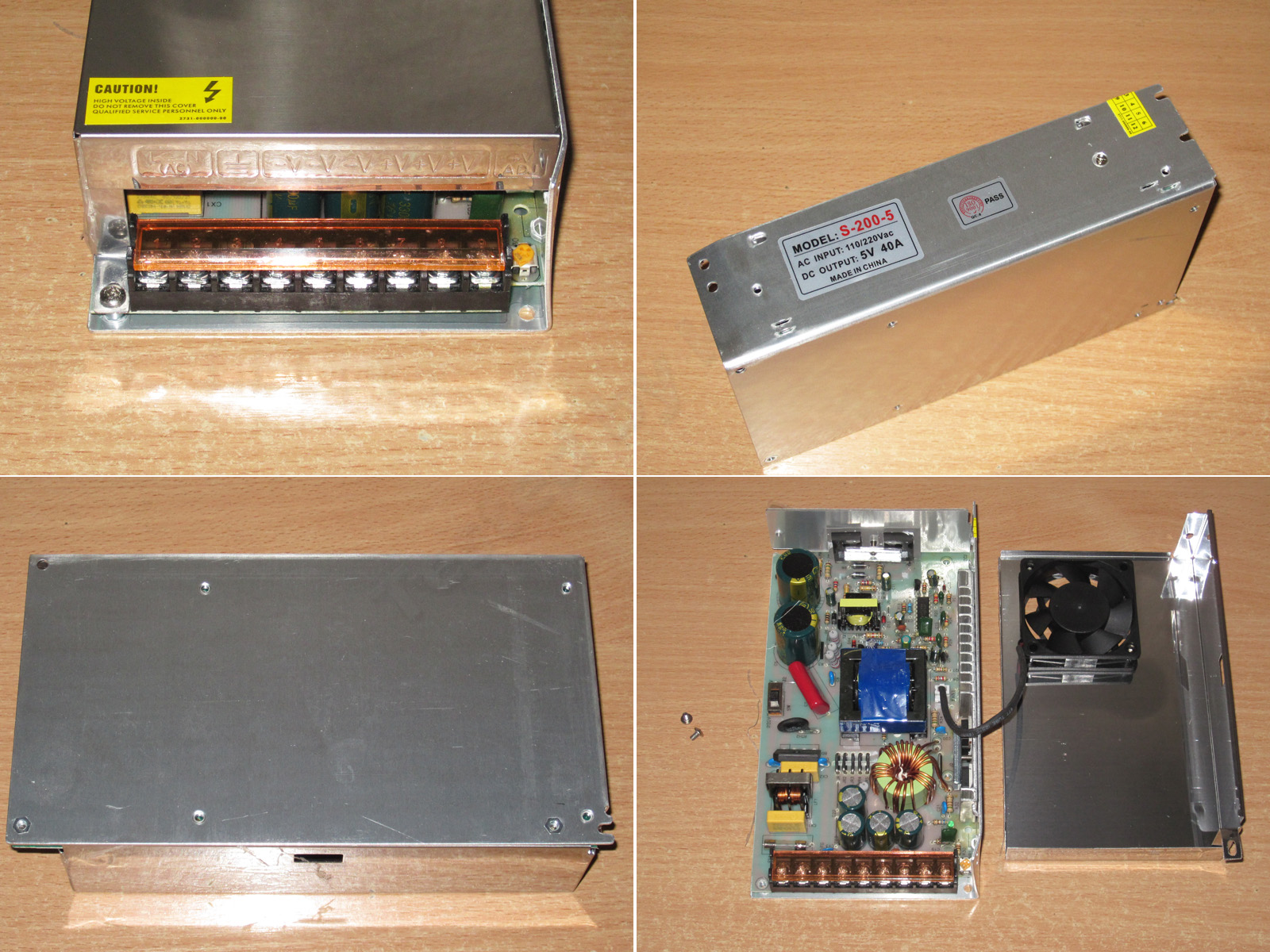
At first glance, it looks much the same, but the cover has no holes, and a potential source of trouble has been screwed onto it: a cheap Chinese fan.
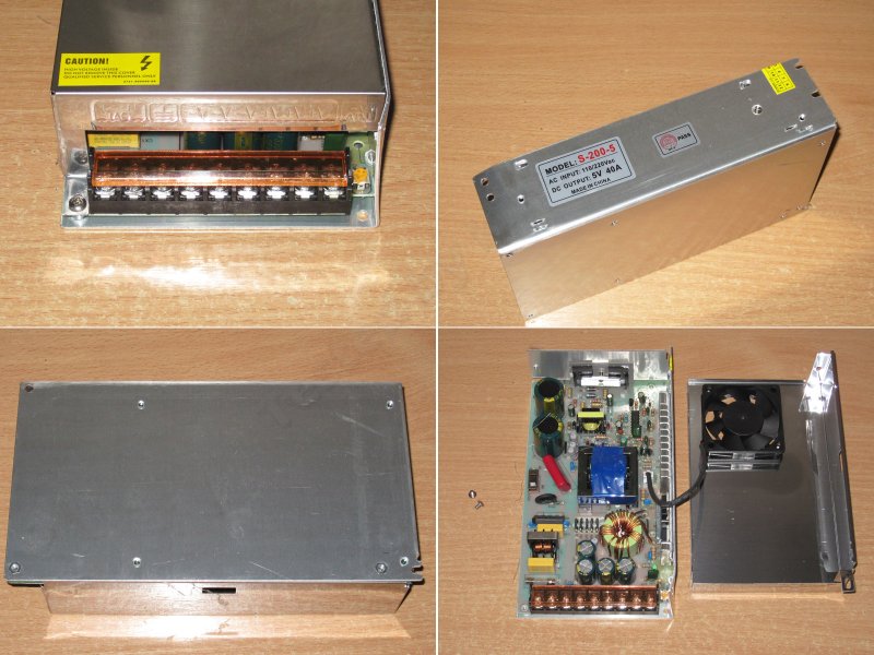
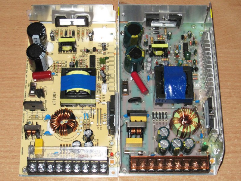
But put the two power supplies side by side, and it becomes clear that they differ in much more than the board color or transformer position.
The input filter has one extra X capacitor.
The snubber resistors are more powerful.
The board is made of fiberglass, not phenolic paper.
The output inductor is actually simpler, though large. That's often how they're made when there's active cooling.
The diodes are mounted on the heatsink I mentioned when discussing the previous 200 W unit.
The output capacitors are beefier, and there are four of them instead of three.
So even from this alone, you can tell this power supply is clearly more powerful than the previous one. With active cooling, it's probably good for more than 200 W.
Subjectively, the board looks better made, mostly because it's fiberglass, which really is better than phenolic paper. Of course, modern phenolic boards, even Chinese ones, are better than the junk with traces that peel off if you so much as bring a soldering iron near them. But they still don't measure up to fiberglass.
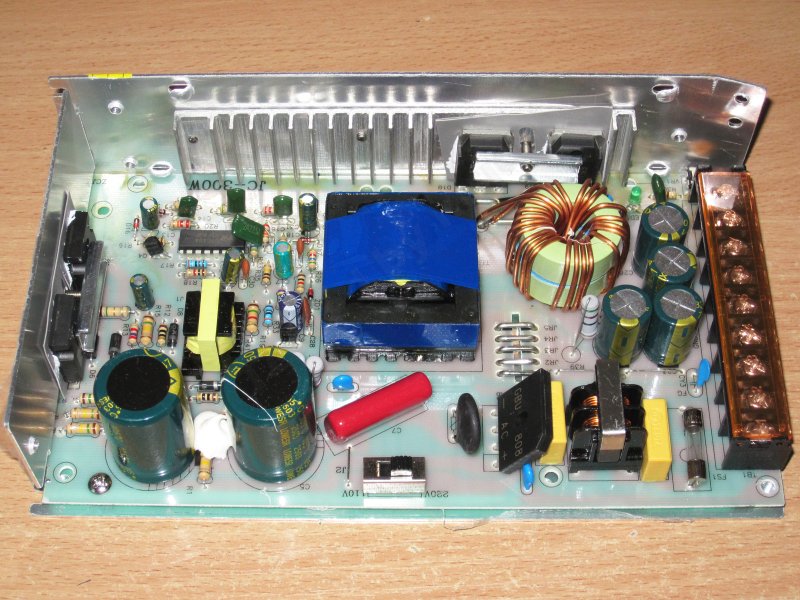
1. The filter and an 8 A bridge rectifier, rather than a 4 A one.
2. The capacitors are also rated at 470 µF (as claimed), but for 250 V instead of 200 V.
3. Even the PWM controller section looks a bit more complete.
4. The transistors are the same 13009s, but there are enough of them here.
5. The diode assemblies are also rated for 45 V, but 40 A instead of 30 A.
6. There are four 3300 µF, 16 V capacitors, rather than three 2200 µF, 10 V ones.
So there's already a substantial difference, even in the small details.
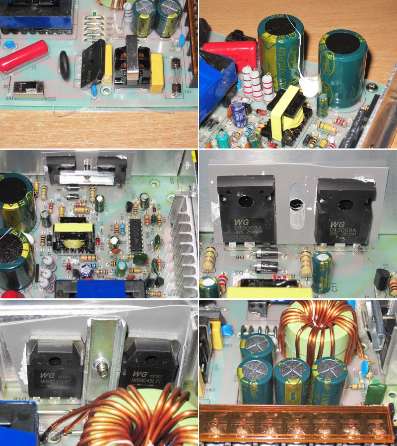
The input capacitors still fall well short of their claimed capacitance, but the previous unit had 260 µF capacitors against a claimed 470 µF. Here they're 290 µF—a small, but real, improvement.
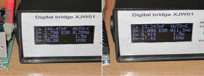
The output capacitance is over 13000 µF, and the ESR is 11 mΩ, even though I measured it at the output terminals here. In reality, it's probably closer to 9–10 mΩ.
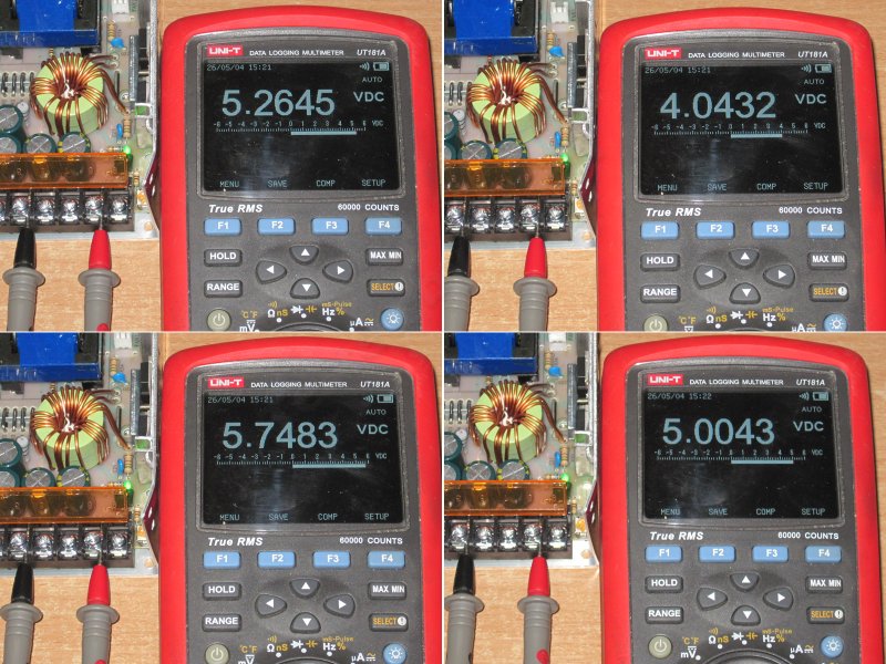
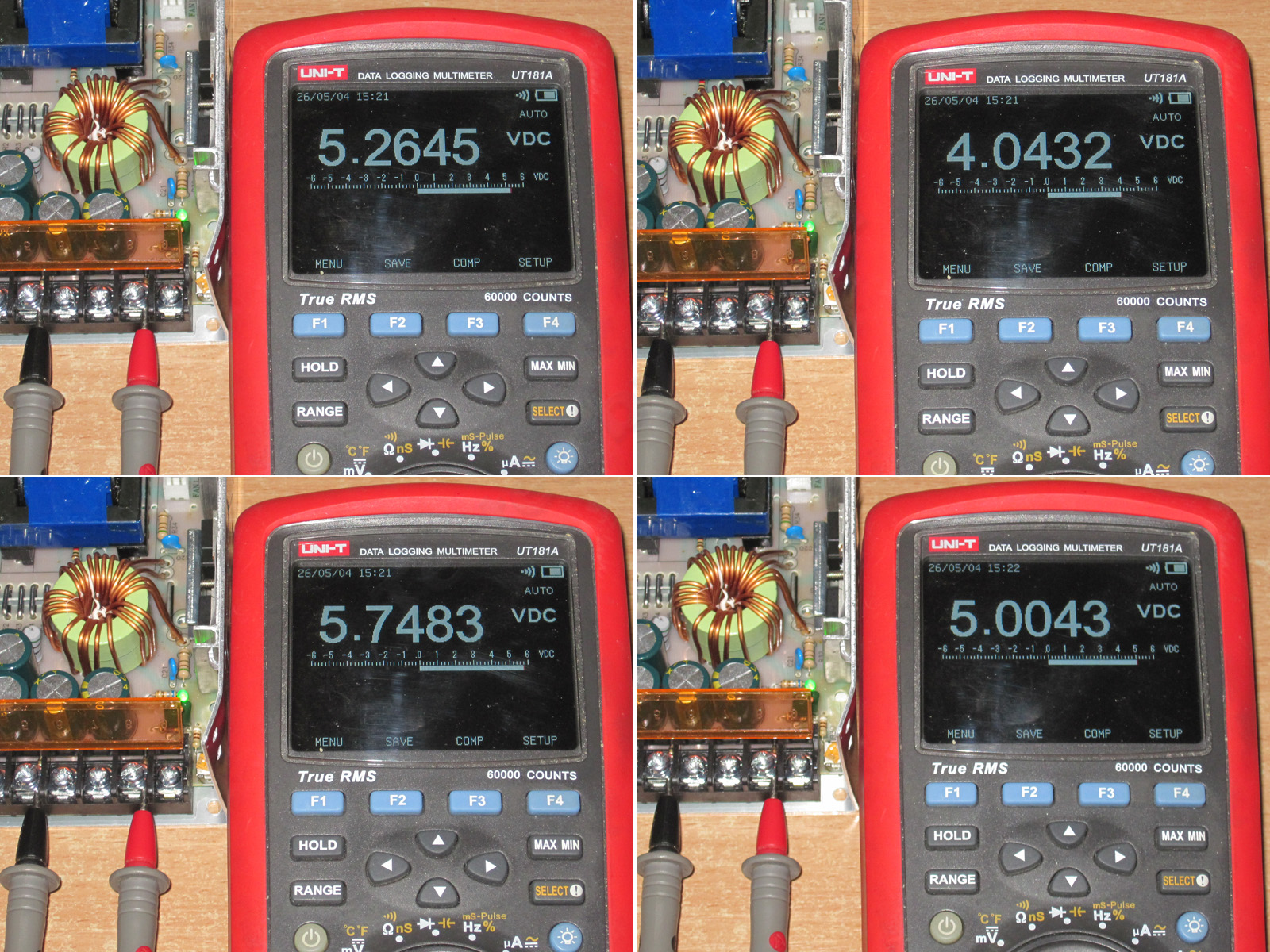
The output voltage was way too high to begin with. The adjustment range is 4.04–5.75 V. Naturally, I then set it as close to 5 V as possible.
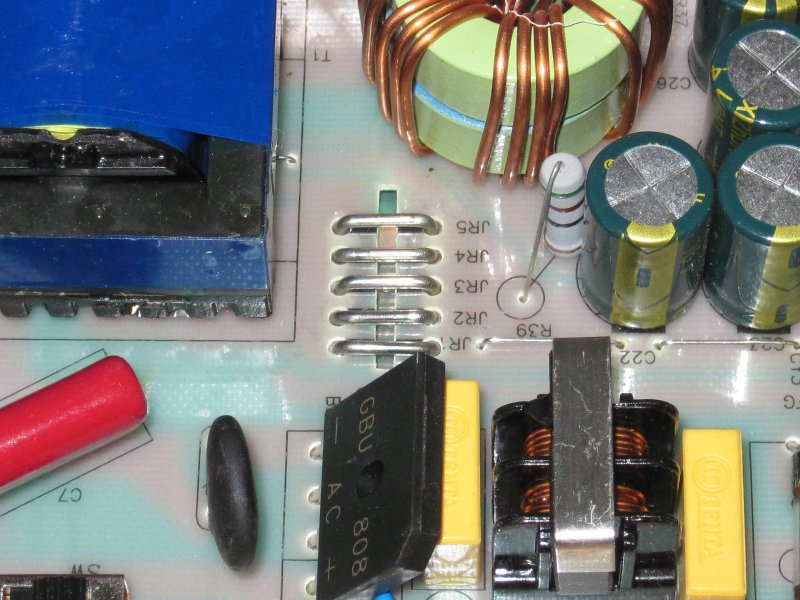
There are even five current-sense resistors here instead of four, so by my calculations the protection should trip at around 50+ A. Wait, did the Chinese take a 50 A unit and label it as 40 A?
For testing the protection, I used a 50 A load. I could have used a 120 A one, of course, but it would have been very inconvenient. I had a feeling 50 A wouldn't be enough, but it worked out.
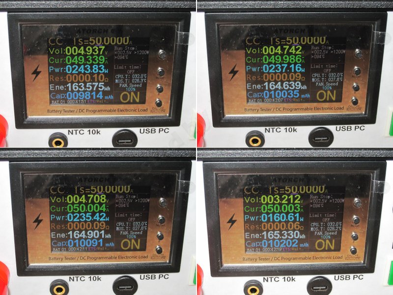
You can see in the photo how the load current rises. It increases gradually here: the current reached its maximum of 50 A, and only then did the output voltage start to drop.
I suspect I caught it right on the threshold. The current was higher when cold, but dropped as the current-sense resistors warmed up. So the actual current here was probably around 49–49.5 A. That puts this power supply closer to 225 W than 200 W.
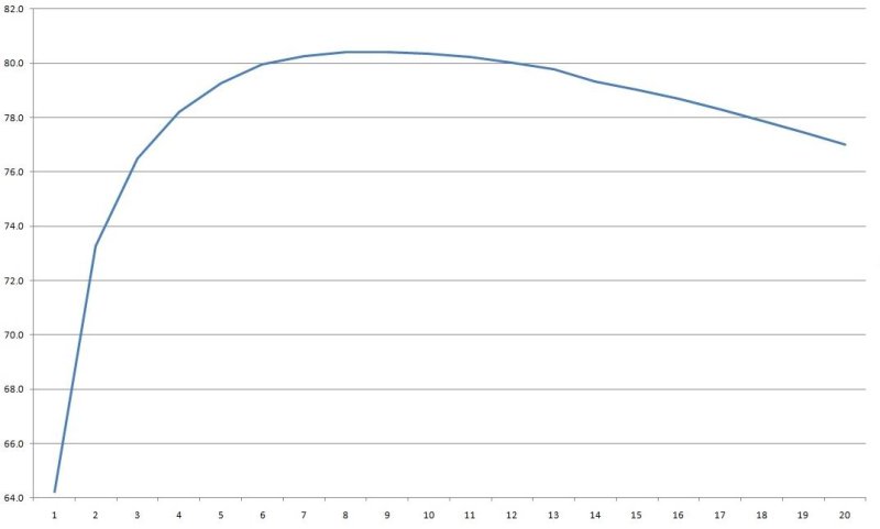
But the efficiency is downright disappointing. I measured it from 2 to 40 A in 2 A increments. At low power levels, I got as little as 56%, though that was probably due to the fan. But even in the middle of the range, efficiency was only 77.5%, compared with 80% for the previous unit—possibly because of the inductor and the fan.
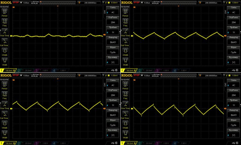
Ripple with no load and at currents of 13, 26, and 40 A.
The results here are clearly better than with the previous unit—noticeably so. Even at 40 A, ripple is around 60–70 mV, versus 160–170 mV on the previous one. The capacitors’ lower ESR makes a big difference.
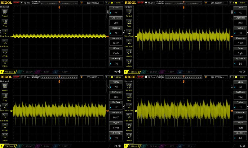
Ripple is noticeably lower even at 100 Hz. Its shape has changed too, but the 100 Hz spikes—and the overall ripple level—are both much lower.
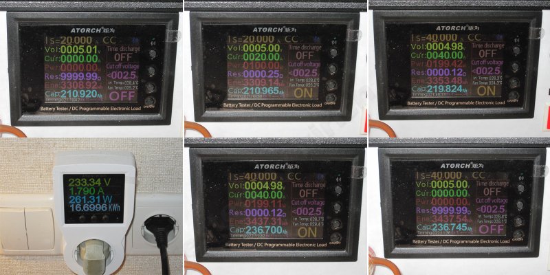
I used a somewhat simplified program for the thermal test here,
First I loaded it to 20 A, then ran it at 40 A for almost half an hour.
1. No load: 5.01 V
2. At 20 A, it dropped to 5 V
3. With the unit warmed up and running at 40 A, it dropped to 4.98 V.
4. It drew 261 W from the mains.
5. With the unit hot and running at 40 A, the output was 4.98 V. After removing the load, the voltage rose to 5 V.
The results are again close to ideal: we lose 10 mV as the unit warms up, and another 20 mV due to the load.
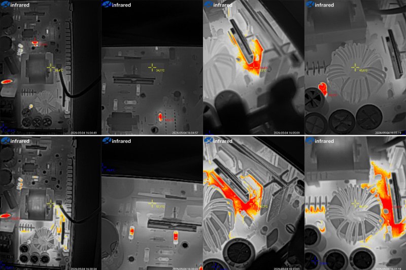
Temperatures.
At 20 A: transformer 40°C, transistors 34°C, diodes 54°C, and inductor 46°C—simply ideal.
At 40 A: transformer 57°C, transistors 57°C, diodes 102°C, inductor 80°C.
The only real criticism here is the diodes. To be fair, the case wasn’t fully closed, since I had to remove the cover during the test. Even so, the temperatures are much better than on the previous unit, which is why I think this is more like a 225 W, 45 A power supply than a 200 W, 40 A one.
Conclusions
10 W - Surprisingly good power supply. It really delivers up to 15 W, has decent components, and is neatly assembled. It could use a lower protection current and an output filter, but it’s perfectly usable as is.
25 W - I’d say it’s decent overall, but in practice it’s good for 4 A continuous at most. Beyond that, the diodes overheat.
40 W - Very good. It has adequate input capacitance, the main components don’t overheat, it easily handles 10 A, and the protection kicks in at 11.5 A, which is fine. Ripple is low too. A more capable output inductor would make it excellent; then it could handle 10 A continuously.
100 W - A decent 75 W power supply, both in terms of build quality and test results, but it can’t deliver 100 W. The output inductor overheats, and the heat-spreader design isn’t great either.
150 W - The results are essentially similar to the 100 W model: actual power is 75% of the rated value, and ripple is fine, but the inductor overheats again, and the output diode assembly gets noticeably hot. I suspect the diode assembly was heating up mainly because of the poor design.
200 W passive - Déjà vu: the same 75% of rated power, but now everything heats up at 100%—the transformer, diode assemblies, and inductor. In other words, the power supply simply can’t handle its rated power, and there’s no way to fix it with a few simple tweaks. Add a heatsink and increase the inductor size, and the transformer will still overheat, so an upgrade isn’t worth it. Ripple is mediocre too, so you’d also have to replace the capacitors, both on the input and output. The one thing I did like was the excellent voltage regulation.
200 W active - This one is a completely different story. It easily handles its rated 200 W, and I think it could deliver more—225–230 W, for example. Ripple and temperatures are both fine, and the construction is better too: instead of a heat-spreader plate, it has a proper heatsink. But they skimped on the input capacitors, so increasing their capacitance would make sense. And the thing I dislike most is the fan—or rather, the cheap Chinese fan. If it had a Sunon fan, I wouldn’t have a word to say, apart from the dust issue. As it is, it’s a mixed bag and suitable only for clean environments.
In short, only the 10 W, 40 W, and actively cooled 200 W models passed the tests completely. The 25 W model has overheating diodes; the 100 W, 150 W, and passively cooled 200 W models deliver only 75% of their rated power. There are also issues with the design and components. That said, all the units are assembled quite neatly.
That’s all for today. Thanks for reading. I really hope you found this useful, and thanks to Vitaly for sending the samples for testing.
These power supplies are often used to power addressable LED strips, LED displays, and similar things, but there’s nothing stopping you from using them for other purposes too.
To keep up with new posts on the blog, I recommend following me on Instagram. I’ll post notifications about new articles there and maybe write about something interesting too - link to my account
You can also follow updates and new articles on the Telegram channel - https://t.me/KirichBlog Note that the channel is open for discussions about reviews and articles, as well as just chatting. I recommend it.
There are a lot of power supplies here. I could have done seven separate reviews, of course, but since they’re all from the same manufacturer, have the same output voltage, and arrived together, I decided to cover them all at once. So this is going to be a long review.
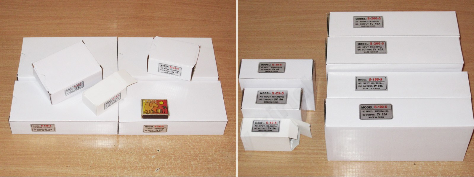
As always, I’ll go from the smallest to the largest, starting with the 10 W model. Here’s the little guy.
Case dimensions: 70 × 39 × 30 mm
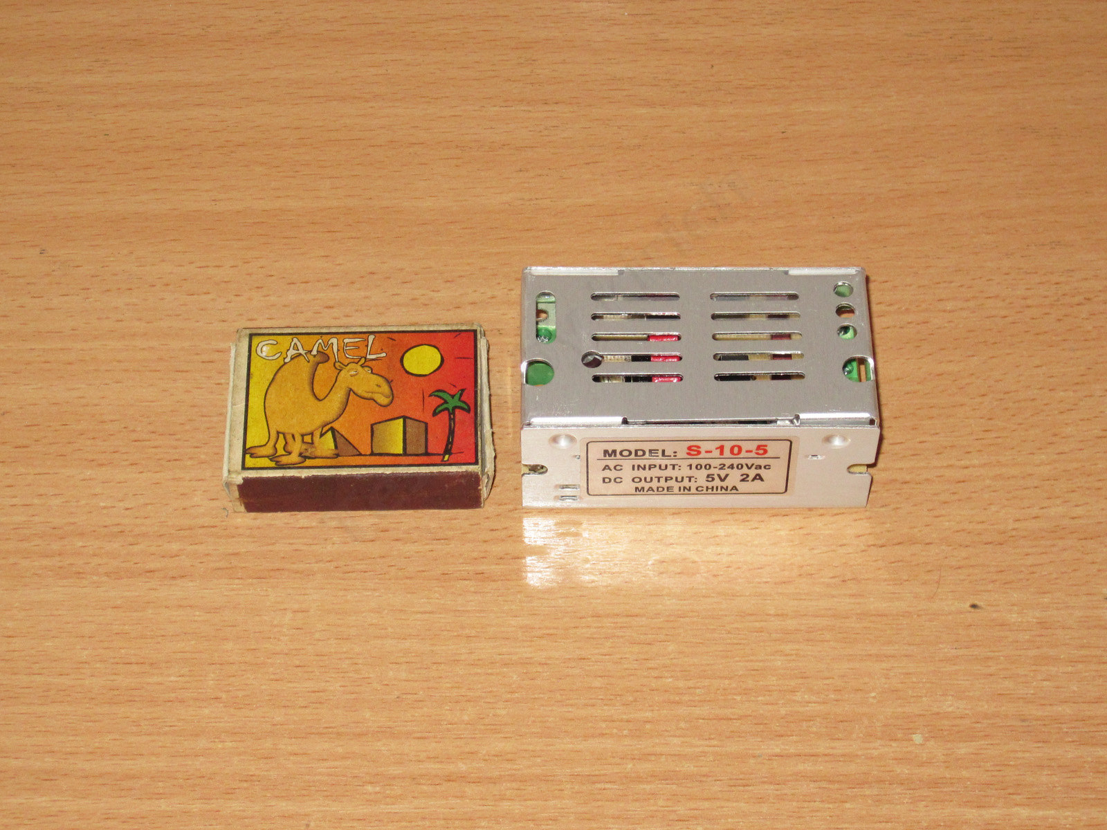
It has an output voltage adjustment and a standard terminal block. Interestingly, even this little guy has a ground terminal.
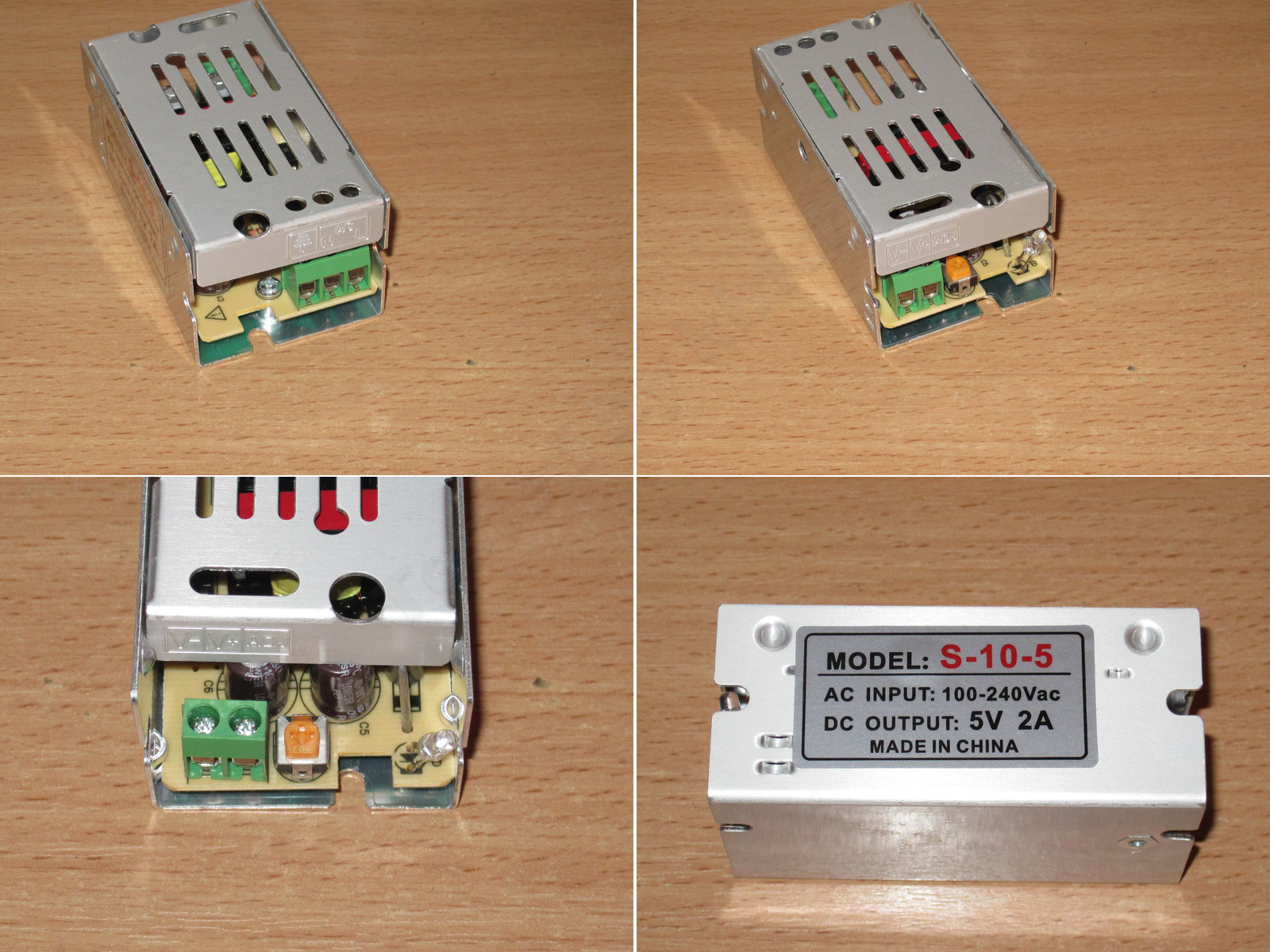
The top cover doesn’t even have any fasteners; it’s basically held in place by the case’s protrusions.
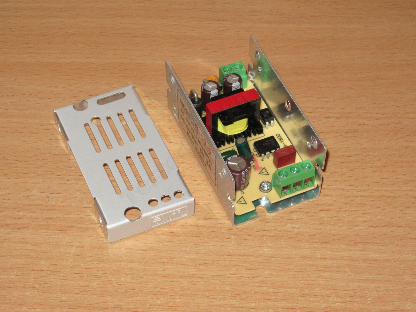
There’s no filter, just a fuse. The input capacitor is made by Aishi, but this is probably the only one of the seven power supplies with branded capacitors.
The output capacitance is 2 × 470 µF, but rated for 16 V, which is massive overkill for 5 V.
The output diode looks like a 5 A part, although diodes in this package are more often rated for 3 A. That seems a bit low for an output current of 2 A, but the tests will tell.
The power supply is built around a dedicated dk1203 PWM controller rated for 12/18 W.
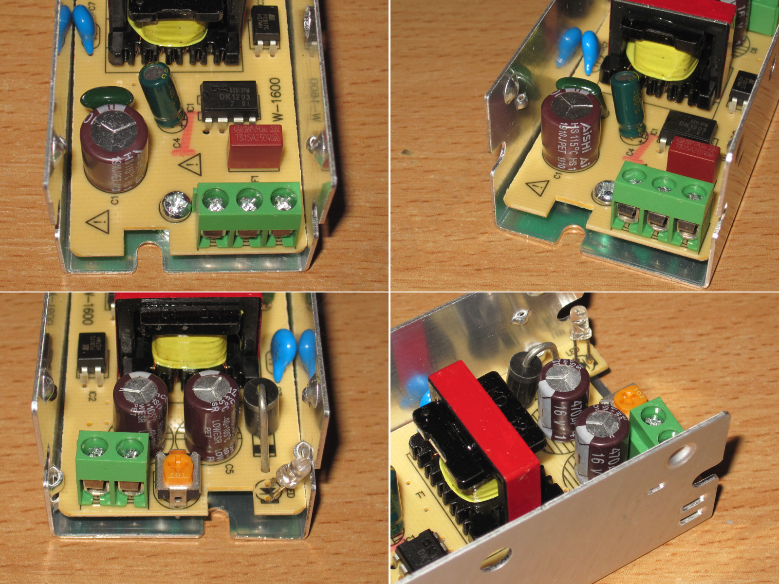
Undo one screw and you can get to the circuit board. It’s a pleasure to take apart :)
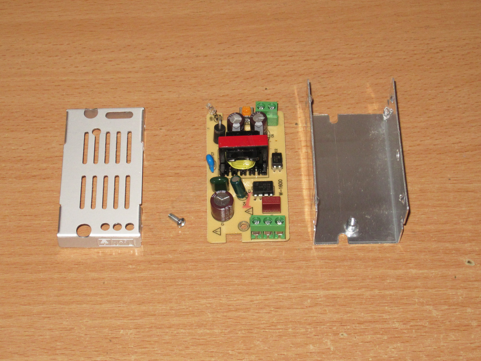
The input capacitor is 10 µF, and there’s a Y capacitor.
By the way, about Y capacitors. I mention them often in my reviews, and I’m very critical when unscrupulous manufacturers use ordinary high-voltage capacitors instead.
The point of a Y capacitor is that it’s safe and extremely difficult to make it fail short. Here are a few details.
The standard strictly prohibits a Y capacitor from failing short, because a short circuit would instantly put dangerous mains voltage (220 V) on the device’s metal case. If the outlet has no ground connection, or the ground wire is broken, touching the case could be fatal.
That’s why, according to manufacturers’ specifications (for example, Knowles, Kemet, and Vishay), certified Y capacitors are designed to fail in a controlled way—open circuit only. The device will stop filtering high-frequency interference, but it will remain completely safe for the user.
That’s why, according to manufacturers’ specifications (for example, Knowles, Kemet, and Vishay), certified Y capacitors are designed to fail in a controlled way—open circuit only. The device will stop filtering high-frequency interference, but it will remain completely safe for the user.
What physically causes them to fail open?
Most modern mains filters use metallized-film or specialized ceramic components as Y capacitors.
There are two ways they can fail open:
Self-healing of the metallized film: When a critical voltage pulse is applied, a microscopic electrical arc forms at the dielectric defect. The extremely thin metal coating (electrode) around that point vaporizes instantly from the heat, in a fraction of a microsecond. The breakdown site is isolated, the short disappears, and the capacitor’s overall capacitance decreases only slightly. After multiple severe breakdowns, enough of the coating evaporates that the capacitor loses its capacitance completely, becoming an open circuit.
Segmented electrodes: The internal plates of Y capacitors are divided into dozens of isolated segments connected by thin metal links (microfuses). If a severe breakdown occurs in one segment, the current rises sharply and the link blows instantly, physically disconnecting the damaged section from the rest of the circuit.
What happens if you use a regular high-voltage capacitor in its place? First, even a Class Y1 capacitor must withstand impulse overvoltages of up to 8 kV, and a Y2 capacitor up to 5 kV. So if you install a regular one, often rated for just 1 kV, the chance of it breaking down is even higher.
This can lead to several problems. First, you could get an electric shock. Second, if the power supply's output side is grounded (which makes a breakdown even more likely), it could cause a short circuit and a fire.
Here's a typical example of this kind of failure (photo from here). Judging by the photo, I can assume that:
1. This is a regular high-voltage capacitor. A characteristic feature of Y capacitors is that their leads are spaced noticeably farther apart and often extend beyond the body, unlike regular capacitors, whose leads are arranged as in this photo.
2. The capacitor is installed between the cold and hot sides of the power supply. The slots in the circuit board also support this conclusion.
But we can also see that the space is designed specifically for a regular capacitor; a Y-type one simply won't fit. The power supply is clearly made in Russia, and most likely designed there too. Perhaps it was designed by students, or perhaps a qualified engineer deliberately came up with this as a way to reduce the population :)
In short, I can live with the quality of the other components, overheating, under-rated power, and so on, but I absolutely do not approve of power supplies that use a regular capacitor instead of a Y-type one.
The underside of the board is clean and tidy, with adequate clearances. No complaints.
The measured capacitance is 8.5 µF for the input capacitor and 810 µF for the output capacitors, though there may be some measurement error.
When I first turned on the power supply, I was surprised to see about 5.5 V at the output, which is clearly too high. Then I was even more surprised: the adjustment simply won't let you set it below 5.03 V. I've never seen that before.
Anyway, I turned it all the way down and continued testing at that setting.
I usually test load capacity by gradually raising the upper limit, but on the first test the power supply easily exceeded my optimistic 3.7 A, so I had to raise the limit. The protection kicked in at 4.4 A.
The protection current seems a bit high to me, but this unit uses a dedicated controller that also provides thermal protection, so there's no need to worry.
Efficiency was measured from 0.2 to 3 A in 0.2 A increments and came out at about 78%. That's a bit low, but given the low output voltage and the power supply's modest power rating, it's quite acceptable.
Ripple with no load and at currents of 1, 2, and 3 A.
At the rated 2 A, the ripple is just about acceptable: 200/300 mV. At 3 A it's a little higher, but still tolerable in principle. If I were the manufacturer, though, I'd add at least a basic filter or replace these two capacitors with a single polymer capacitor. The cost would be about the same, with lower ripple and a longer service life.
No complaints about the low-frequency ripple.
Load testing was carried out in three stages, at currents of 1, 2, and 3 A.
The output voltage barely changes with load, and it barely changes with temperature either. The 10–20 mV of fluctuation is insignificant.
Temperature readings:
1 A — transformer and PWM controller around 45 °C, output diode 56 °C. Excellent.
2 A — transformer 59 °C, PWM controller 63 °C, output diode 76 °C. Also excellent.
3 A — transformer and PWM controller around 92 °C, output diode 117 °C. Just about acceptable, but since this is 150% of the rated load, still excellent.
The second model is more powerful, rated at 25 W, and the case format is noticeably different.
Case dimensions: 85 × 58 × 38 mm.
A typical terminal block, adjustment knob, LED, and a very typical way of opening it. Anyone who's ever taken apart one of these power supplies will know the drill.
The layout is also typical, with plenty of room for the components, but there's no input filter at all.
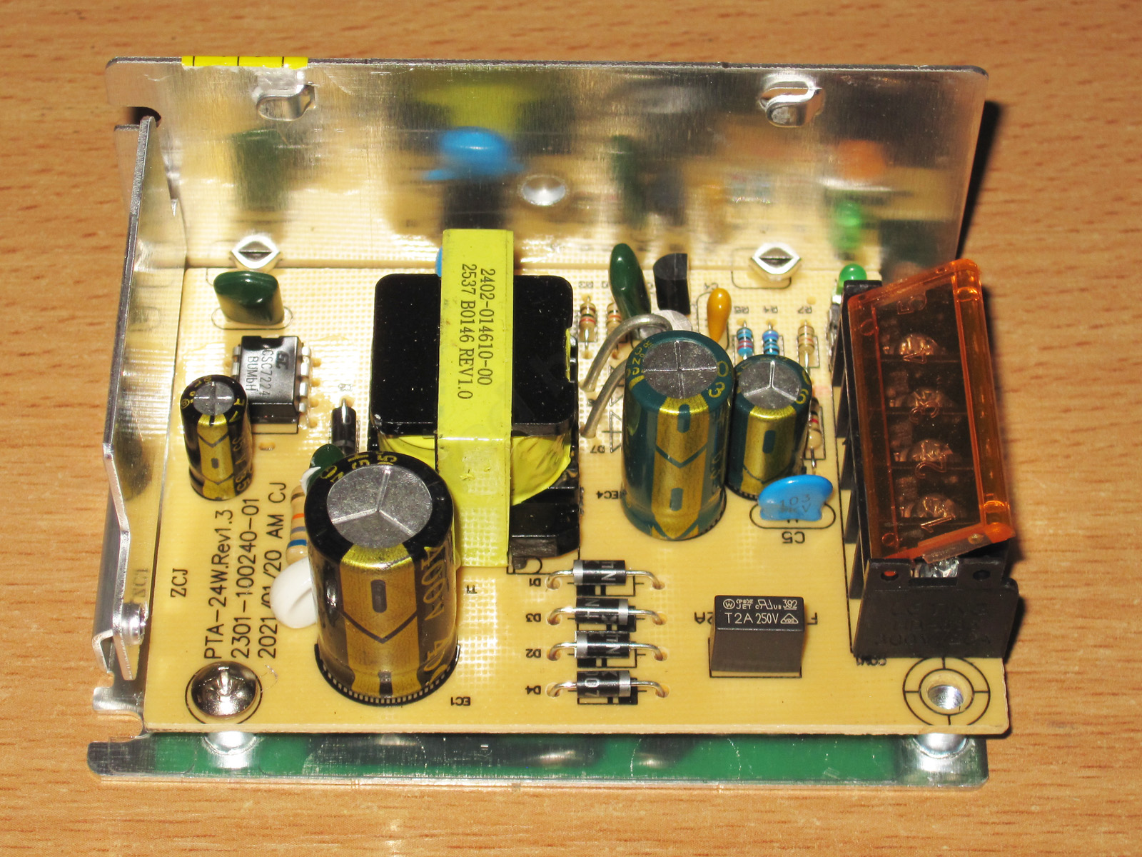
1. The input capacitor is rated at 47 µF, but the unusual font and suspiciously small size for that capacitance made me doubt it.
2. This model is based on the CSC7224 chip, a PWM controller with an integrated high-voltage transistor. It is designed for power supplies rated at up to 18 W over an input range of 85–265 V. With a narrower input range, the power rating should be closer to 24 W, which is near the advertised figure.
3. A Y capacitor is present
4. The output has two diodes in parallel, as well as two capacitors, 3300 µF and 1000 µF, rated at 6.3 V. They even fitted a small inductor.
I have no major complaints about the circuit board, although some of the clearances could have been a bit larger.
The input capacitor's actual capacitance is about 16 µF, so it's a relabeled 22 µF capacitor. That clears things up.
The output capacitors have a combined capacitance close to 4000 µF, which is quite enough for the advertised 5 A output current.
The voltage adjustment works fine here. It was 5.03 V out of the box, and can be adjusted from 4.58 to 5.55 V. I had no trouble setting it to 5.001 V.
Given the chip they used, I expected the overcurrent protection threshold to be lower. In reality, it trips at 7.8 A when cold and 7.7 A when hot. But that's about 38–39 W, compared with the advertised 25 W, so perhaps it's fine.
The voltage regulation is very good, by the way.
Efficiency measured from 0.4 to 6 A in 0.4 A increments. The result is about the same as for the previous model: it could be better, but it's acceptable.
Ripple with no load and at currents of 2, 4, and 6 A.
For a 5 V output, it's rather high: 150/200 mV at 4 A and 220/280 mV at 6 A. It's not exactly a disaster, but considering there's a tiny filter here and the output capacitance is quite substantial, it's still a lot.
At low frequency, we see the same peak-to-peak amplitude, but the low-frequency ripple is small, so this is OK.
The load test was run at 2.5, 5, and 4 A. You'll understand why later.
I have no complaints at all about voltage stability. By the way, the lower the power supply's output voltage, the more critical this becomes.
Temperature test.
At 2 A: transformer 56 °C, PWM controller 89 °C, diodes 80 °C. That's rather hot.
At 5 A: transformer 66 °C, PWM controller 94 °C, but the diodes reach 130 °C—far too hot. So I reduced the current to 4 A for the next test.
At 4 A: transformer 70 °C, PWM controller 90 °C, diodes 118 °C.
So the actual maximum continuous current here is no more than 4 A, limited by the output diodes. You might ask why the previous model, with one diode, managed 3 A, while this one reaches the same temperature at 4 A with two diodes—shouldn't it manage 6 A? It's quite simple: although there are two diodes, they're right next to each other and heat one another, so the current rating is only a little higher than the previous model's.
The third test subject: 40 W, 8 A.
It's basically similar to the previous one, but the dimensions are now 110 × 77 × 37 mm.
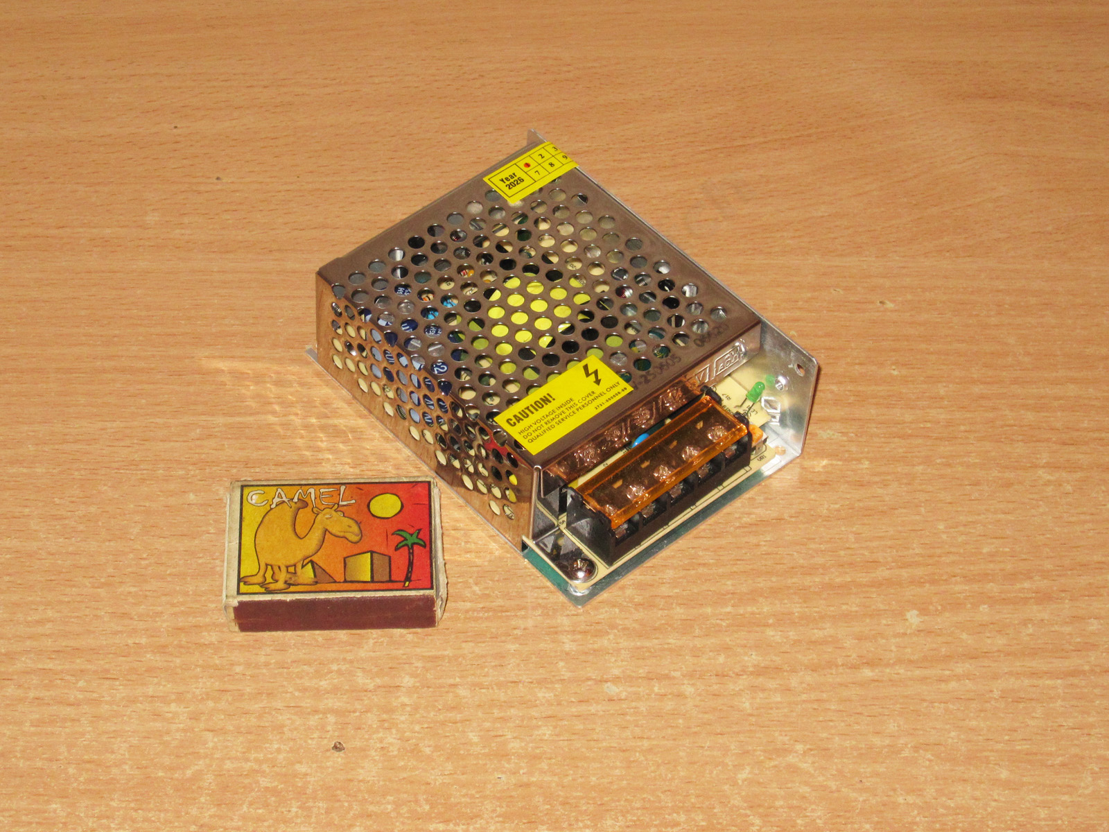
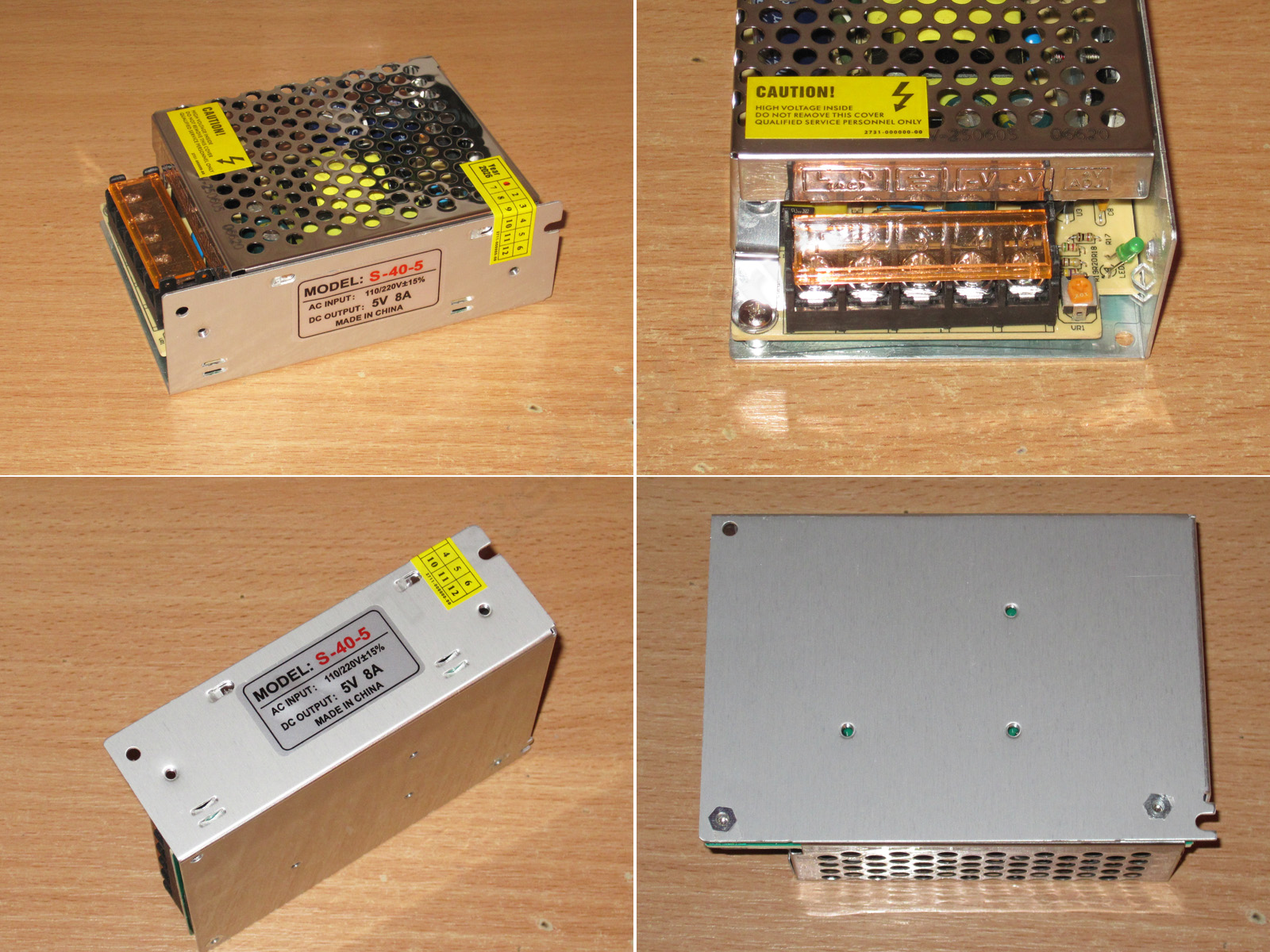
The case, terminal block, and so on are very similar, but this one has extra mounting holes on the bottom, which can sometimes come in handy.
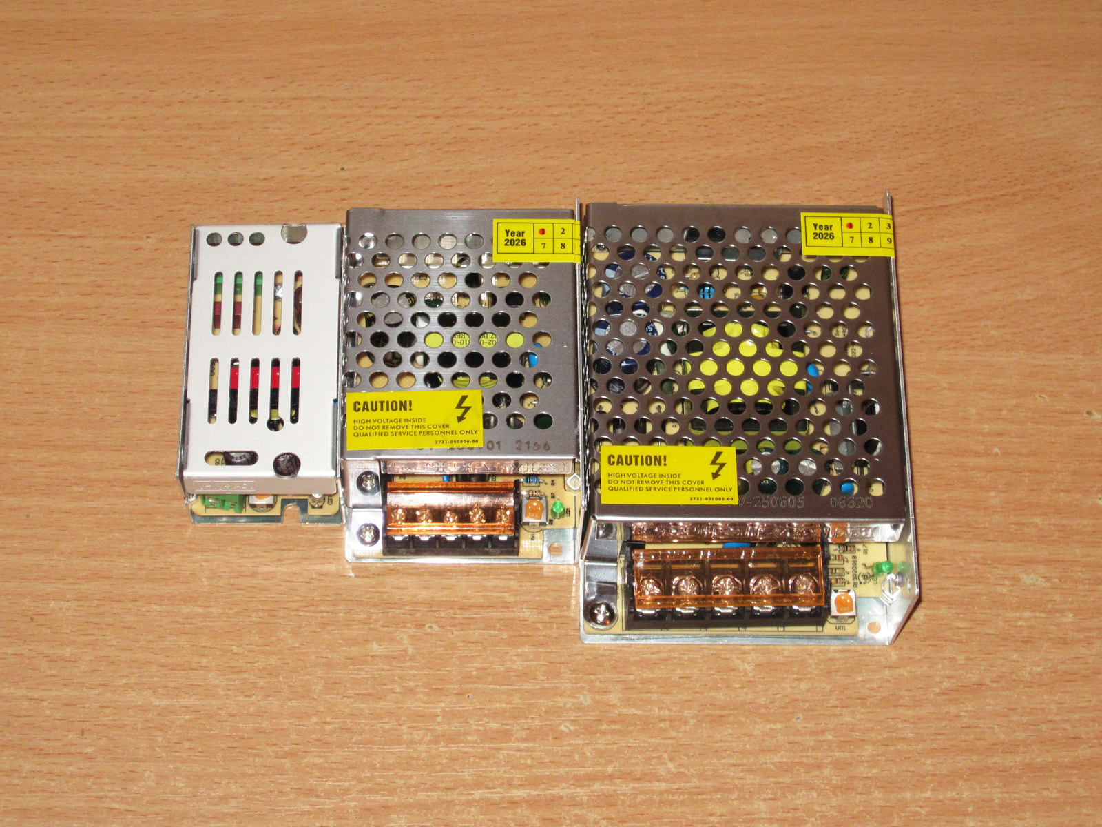
Here are all three models side by side to show the difference in size.
Let's open it up and see what's inside.
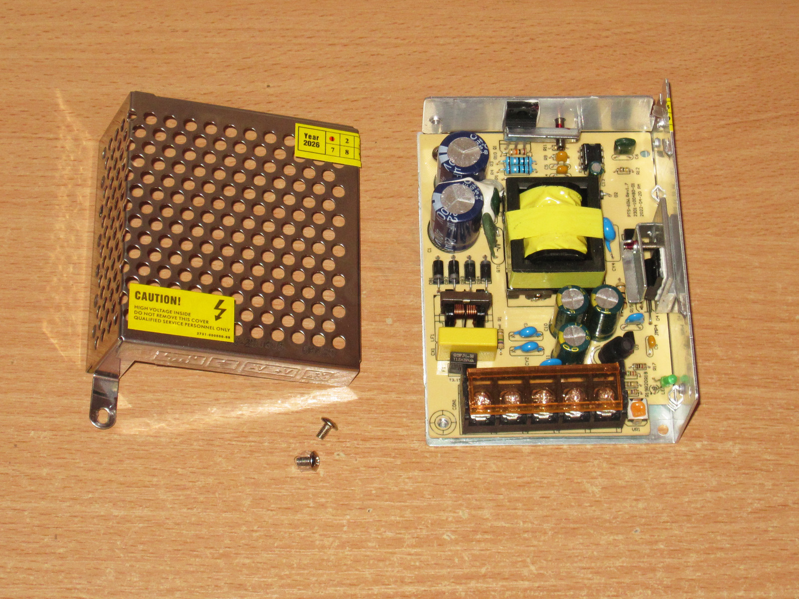
This one is better: a decent-sized transformer, a PWM controller with an external transistor, and the output diode is bolted to the case (no idea what stopped them doing that on the previous model). They even fitted an input filter and a thermistor—now that's luxury :))))
There are two 22 µF capacitors on the input, the PWM controller is coated in lacquer, and the transistor is rated for 5 A and 650 V. Nothing unusual.
A Y capacitor is present, and the rectifier bridge is rated for 20 A and 45 V—perfectly fine.
There are three 3300 µF, 10 V capacitors on the output, which is quite enough. They also fitted an output inductor to reduce ripple.
There are additional noise-suppression capacitors too: two Y capacitors and one regular one. That's fine, since the regular one is essentially in series with a Y capacitor.
It's interesting that they fitted a heat spreader under the output diode even though the current is relatively low. I don't like these in the "Chinese" style, though, where they try to attach one crooked part to another that's just as crooked—and don't even use thermal paste.
I have no complaints about the board's safety or workmanship.
I did all the measurements with my multimeter, using the LCR meter mostly alongside it, but this is where I ran into the first oddity.
The input capacitors are fine—in fact, excellent. 40 µF for a stated 2 × 22 µF is good.
But the output capacitors were puzzling. The calculated value should be around 10000 µF, and the multimeter showed roughly that. Fnirsi, however, not only disagreed completely, but its readings were all over the place, like a sailor after a night at the bar. All in all, I'm more inclined to trust the multimeter here.
The initial output voltage was 5.08 V. The adjustment range is fairly narrow, from 4.9 to 5.38 V, but since the adjustment was smooth, I had no trouble setting it to almost exactly 5 V.
The power supply handled a 10 A load without a fuss, although the output voltage dropped by about 0.09 V—not a major issue, just noticeable.
This test was done with a ZKEtech EBC-A10H electronic load, which has a maximum current of 10 A. I wanted to continue testing with an EBC-A40L, but its maximum voltage is 4.7 V, I think. What a shame—it would have been handy for plotting graphs.
I had to connect a more powerful load, which I used for the rest of the tests. The protection kicks in at around 11.5–11.6 A, which is perfectly reasonable for a stated current rating of 8 A.
Efficiency was measured from 0.6 to 10 A in 0.6 A increments, with only the final step using 0.4 A increments.
And somehow the result was worse than the previous units: 74% at best, and even that was only at the peak. Otherwise it was lower, closer to 73%.
Ripple with no load and at currents of 3, 6, and 9 A.
This is beautiful, though: even at 9 A, ripple is no more than 40 mV, despite the stated maximum current of 8 A.
At low frequencies, though, 100 Hz ripple shows up. In absolute terms it's not that large, with a total swing of around 80 mV, but relative to the rest it looks ugly. The input capacitors have enough capacitance for this power level.
The load test was run in three modes, at 4, 8, and 10 A, for intervals of 20–30 minutes.
The test also showed that the voltage is practically unaffected by temperature, but does vary with load by about 0.1 V. That's within spec, but they could have done better.
Temperatures.
At 4 A: transformer 51 degrees, transistor 39 degrees, output diode 50 degrees, output inductor 55 degrees.
At 8 A: transformer 74.5 degrees, transistor 54 degrees, diode 78 degrees, output inductor 107 degrees. Everything is fine except the inductor.
At 10 A: transformer 86.5 degrees, transistor 62 degrees, output diode 95 degrees, inductor temperature exceeded 135 degrees.
Everything is excellent except the inductor. The power supply handles even 10 A with ease, not to mention its rated 8 A, but they could have used an inductor rated for a higher current.
The transformer windings were just over 100 degrees at 10 A, which is normal. But in the screenshot on the right, at the very bottom, you can see a resistor that heats up to over 135 degrees. Apparently it's the snubber resistor, and I would at least use one with a higher power rating.
The 100 W model, rated for 20 A.
Here we get an even more familiar form factor—pure classic. Dimensions: 199x97x42 mm.
There's not much to comment on here; it's all typical for power supplies like this.
The layout and circuit design are so classic that they make me nostalgic; they immediately bring the early 2000s to mind.
There's an input filter, complete with an inductor, an X capacitor, and a thermistor—in short, all the essentials.
The input capacitors are marked 220 µF, but we'll check that.
The circuit is a familiar design based on the TL494/KA7500 and their many clones.
The 13007 transistors are more than adequate for 100 W.
There's also a whole array of Y capacitors, which is a good thing.
The output diode assembly is rated for 30 A and 100 V. I would have used a 40 A, 45 V part instead; it would run cooler.
Because of the topology, there's an output energy-storage inductor, in this case wound on a single powdered-iron core.
The output has five 2200 µF, 16 V capacitors, which is plenty in terms of both capacitance and voltage rating, although 10 V capacitors would have been enough.
The board is neat and clean; I didn't spot any flaws. It's actually hard to mess this up, but some people still manage it from time to time.
The clearances are adequate here, too, and there's a slot under the galvanic isolation transformer (TGR).
Note that the board has holes aligned with the power supply's mounting holes. That's a thoughtful touch—you won't end up driving a screw into the board.
I ran into a problem while measuring capacitance here. The input capacitor was fine: the multimeter read 95 µF. Fnirsi was less optimistic at 90 µF, but that's down to the measurement mode. In any case, the capacitance is close to the stated value (it should be 110 µF) and is normal for a 100 W power supply.
The output capacitors were another story. The multimeter refused to measure them at all, while Fnirsi first gave a much lower reading, and then the readings fluctuated quite a bit. When I disconnected the bias, the reading started jumping all over the place, from zero to 14,000 µF.
I had to bring out the old XJW01, which showed the youngsters how it's done: 10,600 µF, with the reading staying practically rock-steady. If it fluctuated at all, it was only in the least significant digit. And the measurement result looks realistic, too.
The output was initially 5.16 V. It can be adjusted from 4.64 to 6.15 V; I set it to 5.01 V for the tests. The adjustment is a little coarse.
The protection is set to about 24 A, which is perfectly reasonable for a 20 A power supply.
Efficiency from 1 to 23 A, in 1 A increments, came out at about 71–72%, typical for budget models with this topology.
Ripple with no load and at currents of 7, 14, and 21 A.
This is quite acceptable overall: 100 mV at the heaviest load. But the ripple doesn't really depend much on the load; at 14 A, it's around 85–90 mV. That's fine considering the fairly high current, and 2% ripple is perfectly normal anyway.
At low frequency and maximum current, peaks at 100 Hz started to become noticeable, but again, everything is within the normal range.
The thermal test was run at currents of 10, 15, and 20 A.
1. Initial no-load voltage: 5 V
2. At 10 A, it sagged slightly to 4.98 V.
3. At 15 A, with the unit already warm, it was 4.96 V
4. At 20 A, once warmed up, it was 4.94 V
5. At 20 A, when hot, it was 4.93 V
6. After removing the load, the voltage rose to 4.96 V.
So, the current causes a drop of about 30–40 mV at 20 A, and temperature causes a drop of about 40 mV. Both effects are negative, but well within the normal range.
Now for the temperatures.
At 10 A: transformer 50°C, transistors 47.5°C, diode assembly 69°C, and output inductor almost 100°C.
At 15 A: transformer 58°C, transistors 61°C, output diode 94°C, and inductor 120°C. So far, the only concern is the output inductor.
At 20 A: transformer 68°C, transistors 86°C, output diode assembly 120°C. The thermal camera went off the scale on the inductor, so it was definitely above 135°C.
The unit can't handle 20 A; its maximum is 15 A. It would perform better with a more powerful inductor and, at the very least, thermal paste between the diode assembly's heat spreader and the case. Another option is to install a more suitable diode assembly rated for higher current and lower voltage.
The snubber resistors also got pretty hot, around 131°C, so it would be better to use higher-power ones.
Next model: 150 W, 30 A.
It's the same size as the previous one: 199 × 97 × 42 mm
The design is identical to the previous model.
In fact, this is the same model as before, scaled up for higher power by replacing some components. The 100 W version is on the left, the 150 W one on the right, while the board itself is marked 180 W. This is perfectly normal practice; it lets you adjust the price a bit if you don't need the higher power.
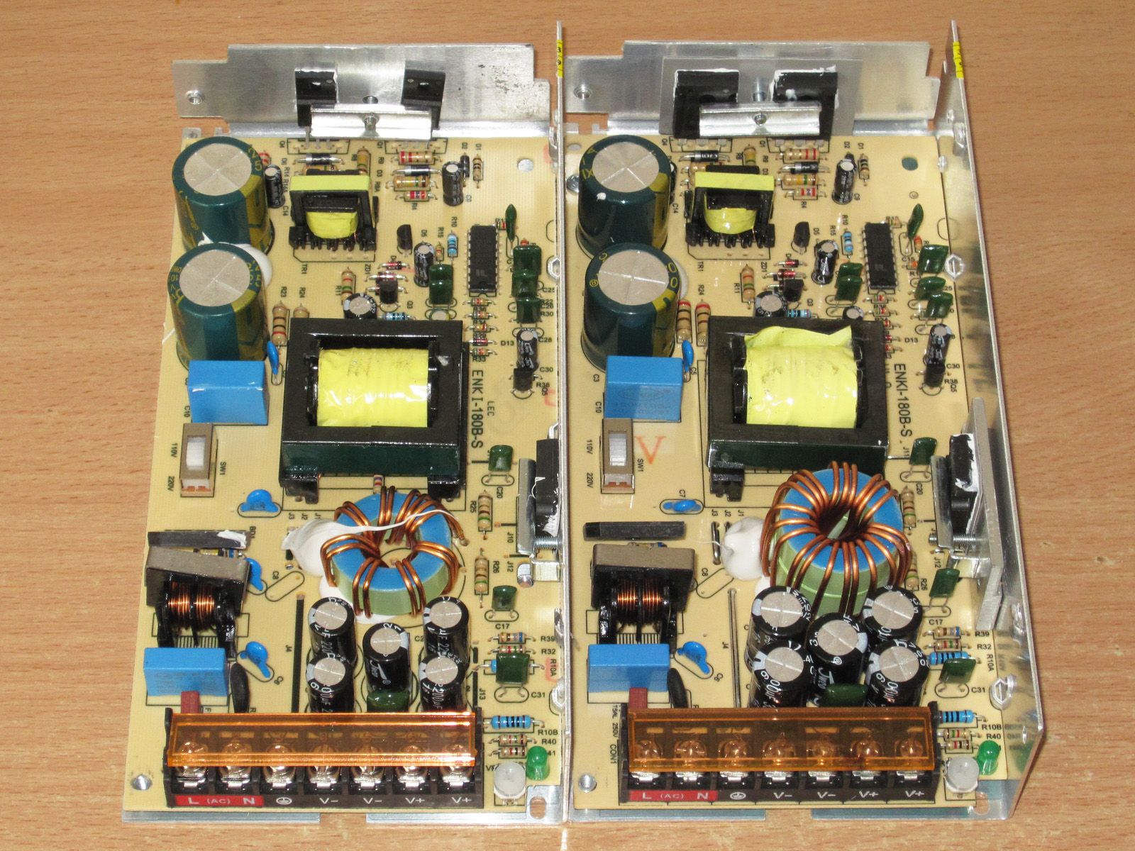
There are a few changes, which I'll list below.
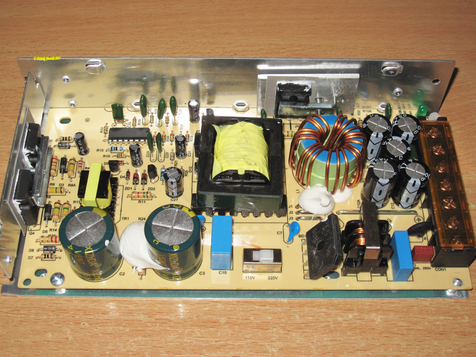
1. The bridge rectifier and input filter are identical
2. The input capacitors are also unchanged, although in this case they would usually use higher-capacitance ones.
3. The transistors have been replaced; these are 13009s now. Damn, I typed their type automatically :)
4. The output diode assembly is rated for 40 A and 45 V. This is what the previous model should have had, and this one could really use two.
5. The inductor is wound on two cores, and the winding now uses three wires instead of two.
6. There are still 5 output capacitors, as before, and they're still rated for 16 V, but now they're 3300 µF.
So far, we can see that almost all the necessary changes have been made, in line with the increase in power.
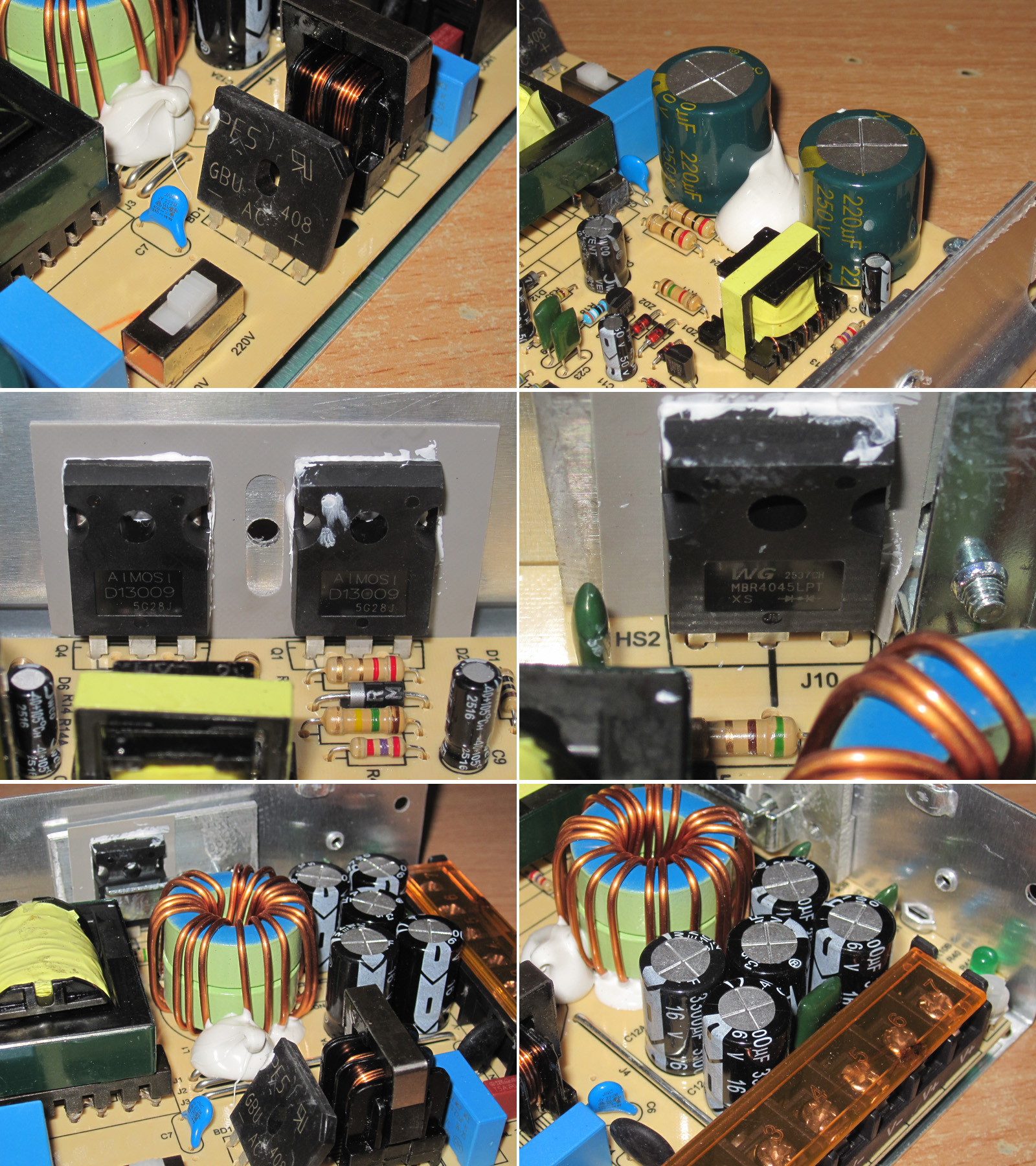
Since the output current is 1.5 times higher, they installed three shunts instead of two. In other words, each shunt corresponds to roughly 11–12 A of output current. Where the previous model had 23–24 A, we can expect around 34–35 A here.
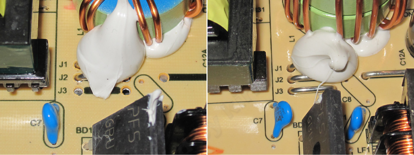
I had trouble measuring capacitance, most likely because of the output ballast resistance, which is usually low at 5 V. So from here on, I took measurements with my old LCR meter.
The input capacitance is 91 µF, as before; the output is about 14,000 µF, which is close to the stated value. The ESR is a little high because I measured it at the terminals rather than directly on the board.
The output was 5.16 V, adjustable from 4.72 to 6.17 V. I set it to about 5 V.
I checked the protection while measuring efficiency. The power supply shuts down at around 34 A, just as I expected.
I measured efficiency from 1 to 33 A in 2 A increments, with the final step in 1 A increments.
I got around 76–78%, which is typical for power supplies like this.
Ripple was measured with no load and at currents of 10, 20, and 30 A.
At maximum current, it was around 65–70 mV, which is actually very good and definitely better than the previous model, which had around 90–100 mV.
At 100 Hz, the ripple is noticeably higher. The input capacitors are the same as before, after all. Still, I think it's perfectly acceptable, especially since these power supplies are unlikely to be used for audio equipment.
The load test was performed in three modes: 15, 22.5, and 40 A, i.e. 50%, 75%, and 100% load.
1. With no load, the voltage is exactly 5 V
2. At 15 A, it dropped to 4.97 V, much like the previous model.
3. At 22.5 A, with the power supply warm, we get 4.94 V
4. At 40 A, once it had warmed up, I got 4.91 V
5. At the same 40 A, but now hot, we get 4.89 V
6. After removing the load, the voltage rose to 4.94 V.
Here, the effect of current and warm-up is a little greater. I'd even say it scales with the increase in power: 60 mV from heating and 50 mV from the load. But that's perfectly normal; you can simply set the voltage a little higher to begin with, which is what I did here.
Temperatures.
15 A — transformer 47 degrees, transistors 41 degrees, diode assembly 59 degrees, inductor around 70 degrees.
22.5 A — transformer 61.5 degrees, transistors 54, diode assembly 83, inductor 102 degrees.
40 A — transformer 79, transistors 75, diode assembly 110, inductor over 135 degrees.
The picture is similar to the previous model: the power supply handles 75% power just fine, but overheats at 100%. And once again, the same components are the problem: the diode assembly and the inductor. Basically, I would at least rewind the inductor with thicker wire or more strands and, as I mentioned earlier, install two diode assemblies instead of one.
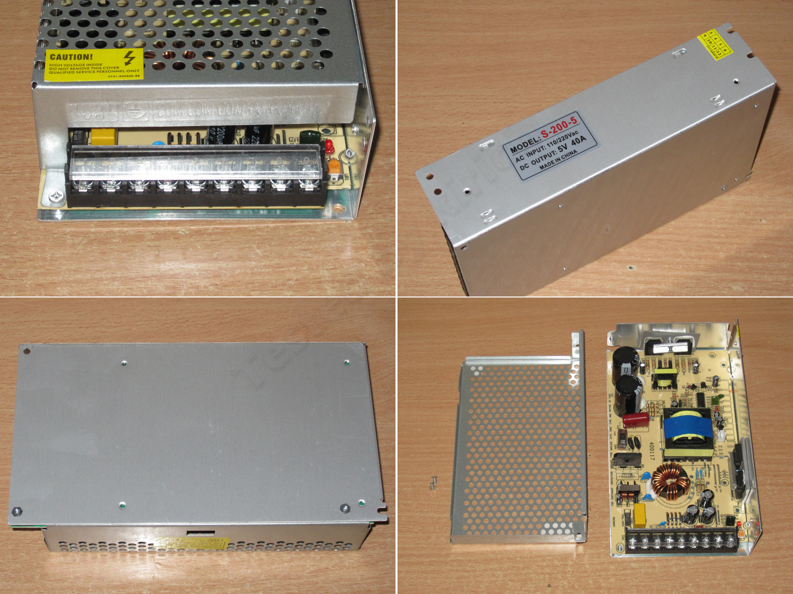
And now the two most powerful power supplies in this lineup: 200 W, 40 A.
Dimensions: 197 × 109 × 50 mm.
There are two versions, with passive and active cooling. I'll start with the first one.
In terms of design, this is the same power supply as the previous models, just a little larger.
The layout is the same, but there are a few changes. The first thing that catches the eye is that there are two input thermistors, while the output has surprisingly few capacitors.
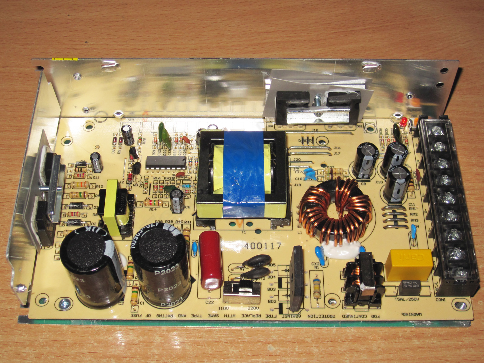
The input capacitors are rated at 470 µF, or 235 µF when connected in series.
The “hot” side is practically identical to the previous models, especially the 150 W version.
The transistors are the same as in the 150 W model: 13009.
There are now two diode assemblies, each rated for 30 A and 45 V.
The output storage inductor is wound with four strands on what is most likely a sendust core. This is more efficient, which is why it uses a single core.
There are three 2,200 µF, 10 V output capacitors. That seems like rather little capacitance for a 40 A output current, in my opinion.
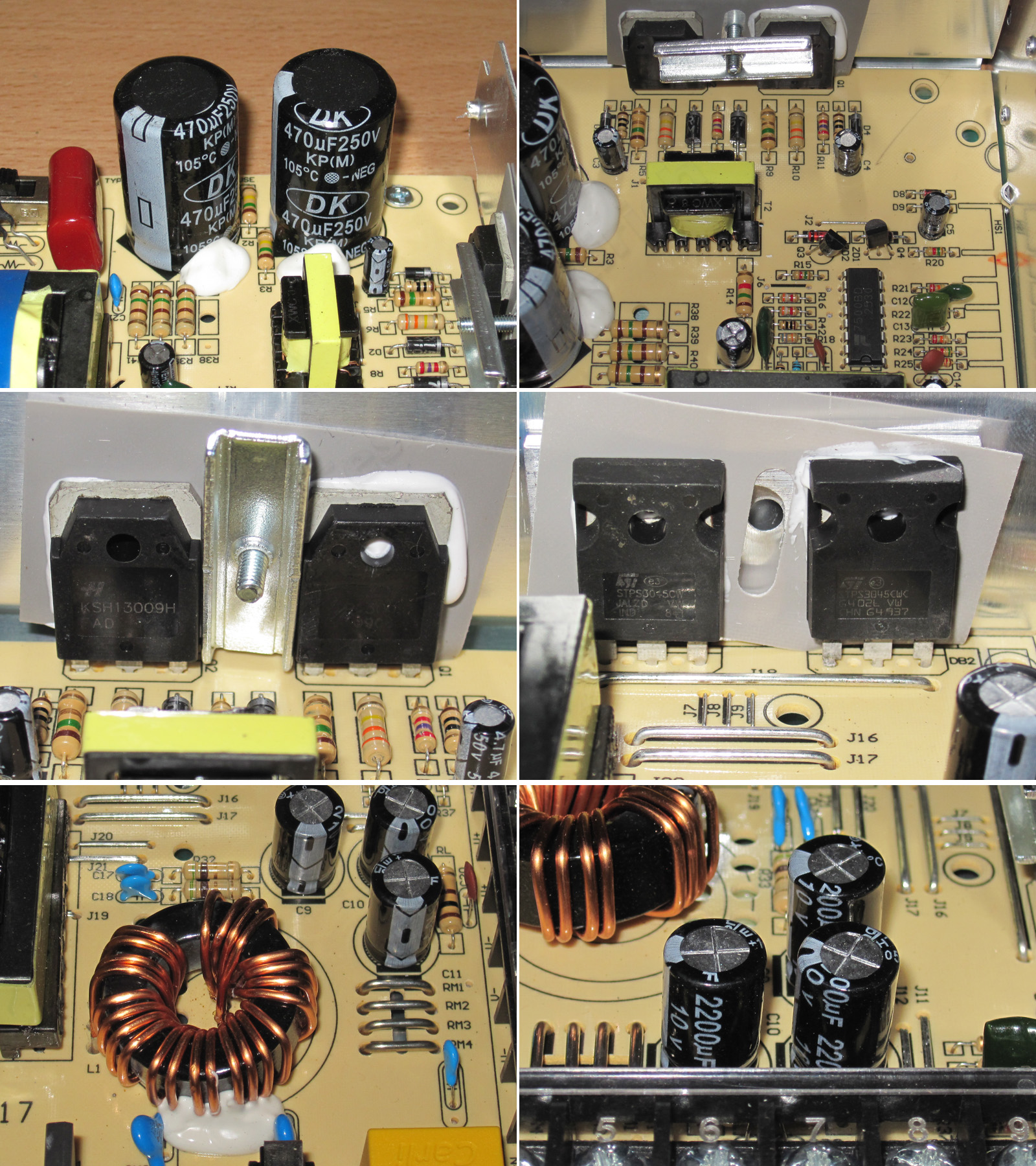
There are four current-sense resistors, in proportion to the increase in current compared with the previous models.
It's interesting that this power supply is so standardized that they even populated the fan power circuit. By the way, you can see the heatsink marking on the board nearby. In my opinion, a heatsink really wouldn't have been out of place here, especially with passive cooling.
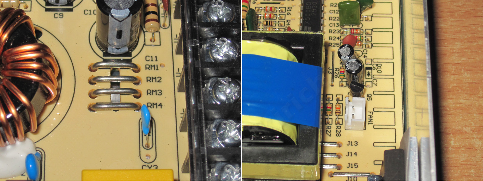
The board has the necessary clearances and slots, but the routing leaves something to be desired: the traces to the capacitors are narrow, which usually has a negative effect on output ripple and radio interference.
The trace width is especially critical here because, although the power supply is only 200 W, it handles 40 A.
But the traces are a minor issue compared with the heat-spreading plate. First, it has no thermal paste. Second, although I put it back in exactly the same position after taking it apart, there was still a noticeable gap between the case and the plate.
I've written more than once that this is a bad design, both literally and figuratively. There's a very good chance the surfaces won't make proper contact, so heat won't be transferred effectively. The plate should be secured with at least two screws, it should be flat, and there should be thermal paste between it and the case.
The input filter capacitance is 130 µF, versus the claimed 235 µF. Looks like these are counterfeit capacitors.
The output capacitance is also a little below spec, but not critically so. The ESR, though, is 18 mΩ, which is clearly too high for a current of 40 A.
The protection trips at around 43.5 A. That's a little below the calculated value based on the number of shunts, but that's perfectly normal: the scaling doesn't always increase in exact multiples as you add shunts.
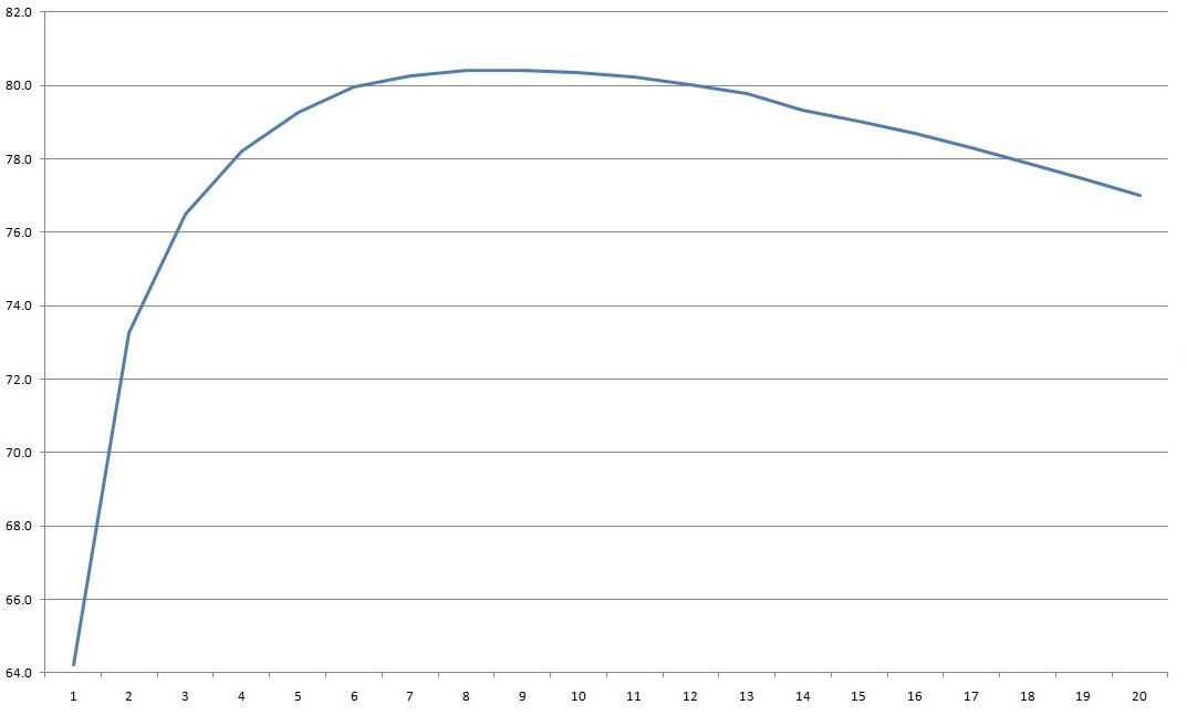
Efficiency from 2 to 40 A, in 2 A increments. Here I even got over 80%, though only over a narrow range. Still, the output inductor's core type deserves a lot of the credit, as does using two output diodes instead of one.
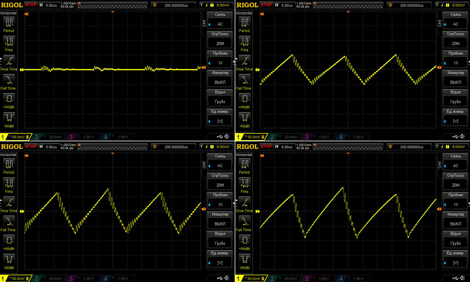
Ripple with no load and at currents of 13, 26, and 40 A.
Well, yes, it's a bit high: 150–170 mV at 40 A. But that was expected, since the output filter's ESR is quite high. I also didn't like the ugly comb-like pattern on the waveforms. Some of that may be due to slightly sloppy PCB routing, but of course I'm not going to check :)
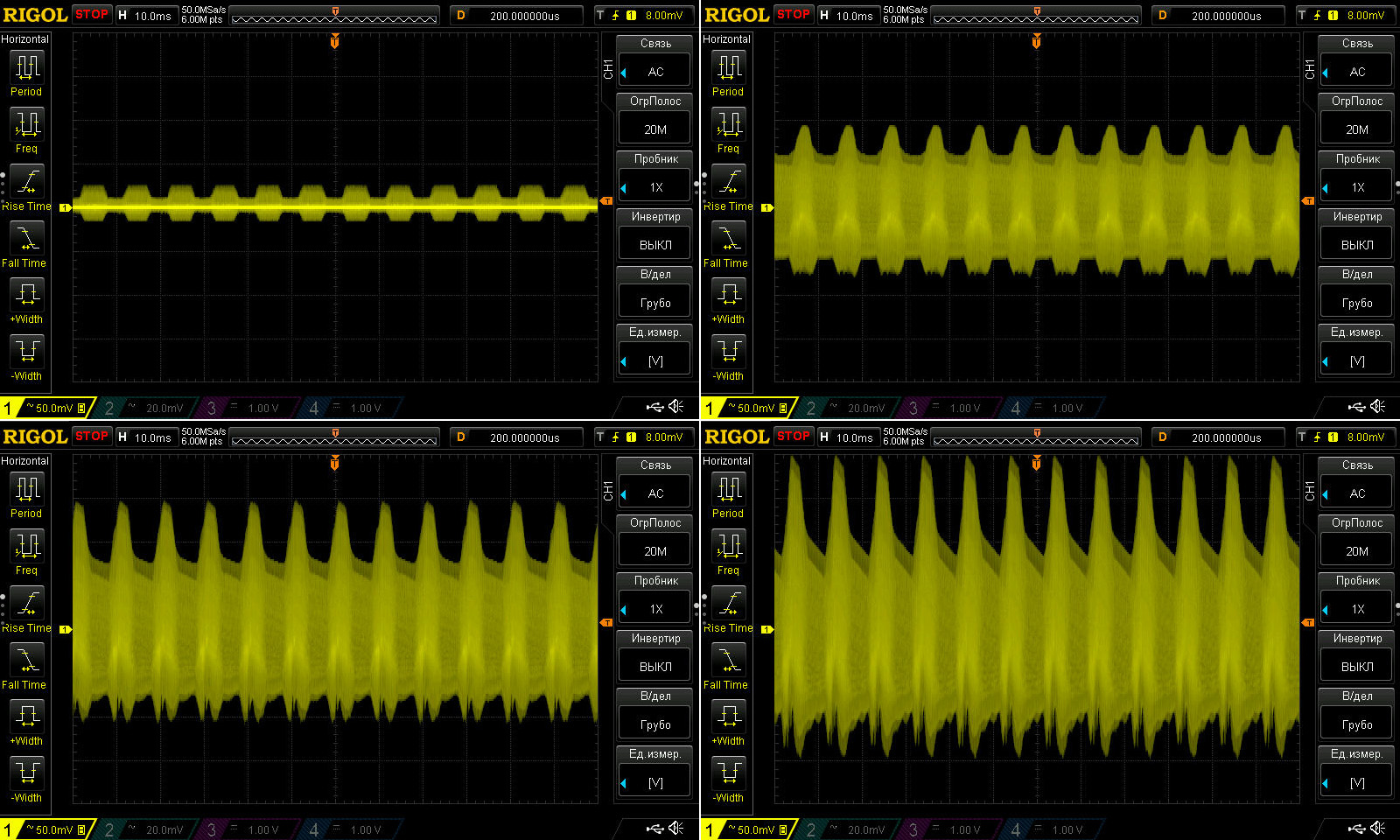
At 100 Hz, the waveform looks pretty unpleasant: there's a lot of ripple at this frequency, and it looks quite ugly.
No, it doesn't usually have much of an effect, but it's still unpleasant. This is probably partly due to the input filter's lower-than-specified capacitance, which may also shorten the capacitors' service life, and partly due to the low capacitance of the output capacitors, the PCB routing, and other parameters of the components themselves.
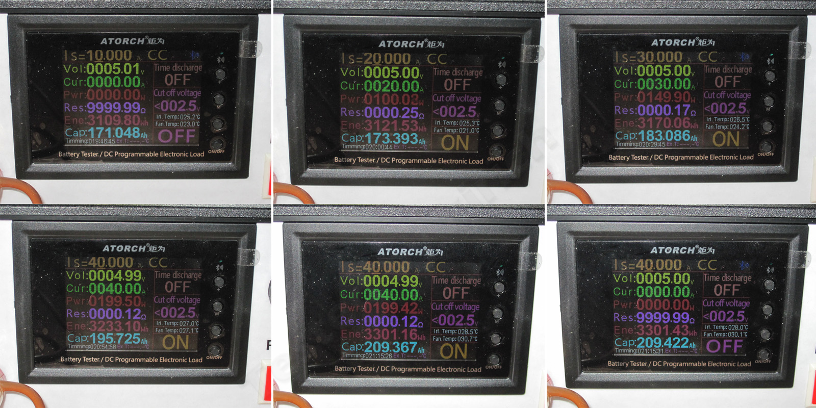
The load test originally went 10-20-30-40 A, but I left the 10 A result out of the photo because it was just a check to see whether the thermal contact of the output diode assemblies was acceptable or needed reworking.
1. No load: 5.1 V
2. At 20 A: exactly volts
3. At 30 A, with the power supply warm: the same 5 V
4. At 40 A, with the power supply already warmed up, there's a slight drop to 4.99 V.
5. Hot, at 40 A: still 4.99 V
6. After removing the load, it's back to 5 V.
Overall, voltage regulation is excellent. The voltage varies by just 10 mV with current, and even then only at the maximum load. A solid 5 out of 5 here.
And now, component temperatures in different operating modes.
20 A — transformer 61 °C, transistors 43 °C, diodes 74 °C, inductor 55 °C. Almost perfect, if not for the diodes.
30 A — transformer 79 °C, transistors 51 °C, diodes 105 °C, and inductor 85 °C. Once again, the diode assemblies run hotter than the other components.
40 A — transformer 101 °C, transistors 70 °C, diode assemblies 126 °C, inductor 125 °C.
So once again, we have a power supply whose long-term maximum is 75% of its rated output. At maximum current, only the transistors stay at a reasonable temperature. Everything else overheats: the transformer, diodes, inductor, even the circuit board, which gets hotter than 135 degrees. The last part was predictable, as I mentioned.
 .
The winding temperature rises sharply with current. At 30 A, everything is fine at 84 degrees, but at 40 A it shoots up to a crazy 127 degrees. Inside the winding, it must be even hotter.
So, the problem with the poor heat-spreading plate was effectively overshadowed by the overheating of other components.
And the last power supply for today: the same 200 W, 40 A, but with active cooling.
The dimensions are the same: 197×109×50 mm.
At first glance, it looks much the same, but the cover has no holes, and a potential source of trouble has been screwed onto it: a cheap Chinese fan.
But put the two power supplies side by side, and it becomes clear that they differ in much more than the board color or transformer position.
The input filter has one extra X capacitor.
The snubber resistors are more powerful.
The board is made of fiberglass, not phenolic paper.
The output inductor is actually simpler, though large. That's often how they're made when there's active cooling.
The diodes are mounted on the heatsink I mentioned when discussing the previous 200 W unit.
The output capacitors are beefier, and there are four of them instead of three.
So even from this alone, you can tell this power supply is clearly more powerful than the previous one. With active cooling, it's probably good for more than 200 W.
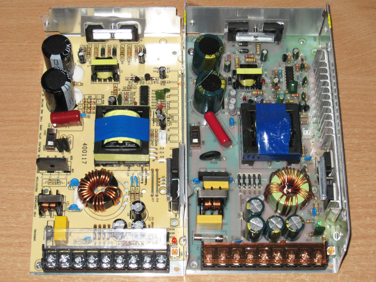
Subjectively, the board looks better made, mostly because it's fiberglass, which really is better than phenolic paper. Of course, modern phenolic boards, even Chinese ones, are better than the junk with traces that peel off if you so much as bring a soldering iron near them. But they still don't measure up to fiberglass.
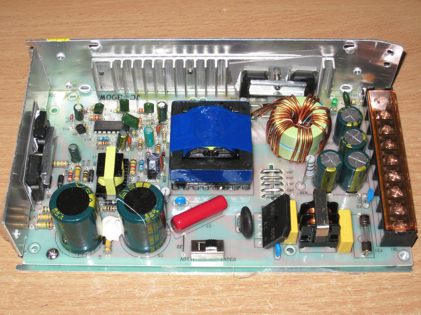
1. The filter and an 8 A bridge rectifier, rather than a 4 A one.
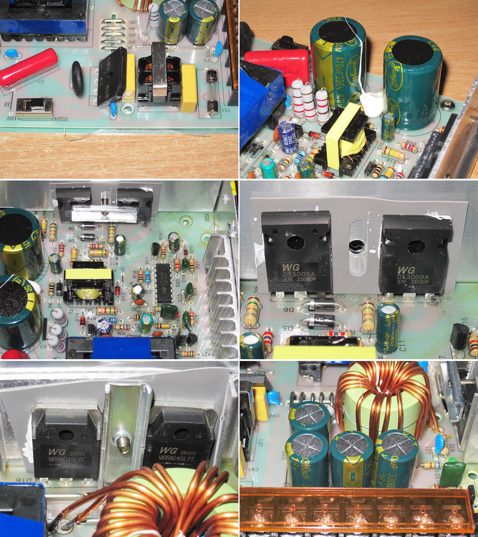
2. The capacitors are also rated at 470 µF (as claimed), but for 250 V instead of 200 V.
3. Even the PWM controller section looks a bit more complete.
4. The transistors are the same 13009s, but there are enough of them here.
5. The diode assemblies are also rated for 45 V, but 40 A instead of 30 A.
6. There are four 3300 µF, 16 V capacitors, rather than three 2200 µF, 10 V ones.
So there's already a substantial difference, even in the small details.
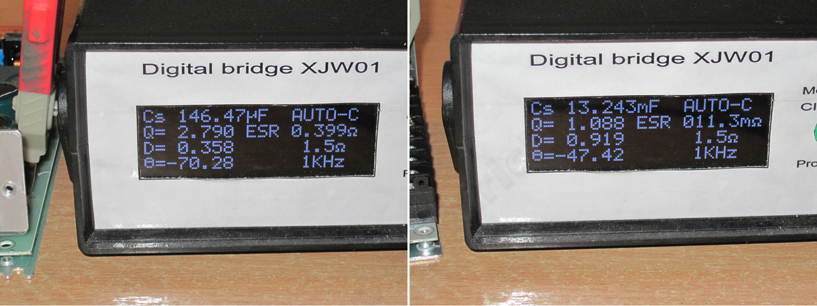
The input capacitors still fall well short of their claimed capacitance, but the previous unit had 260 µF capacitors against a claimed 470 µF. Here they're 290 µF—a small, but real, improvement.
The output capacitance is over 13000 µF, and the ESR is 11 mΩ, even though I measured it at the output terminals here. In reality, it's probably closer to 9–10 mΩ.
The output voltage was way too high to begin with. The adjustment range is 4.04–5.75 V. Naturally, I then set it as close to 5 V as possible.
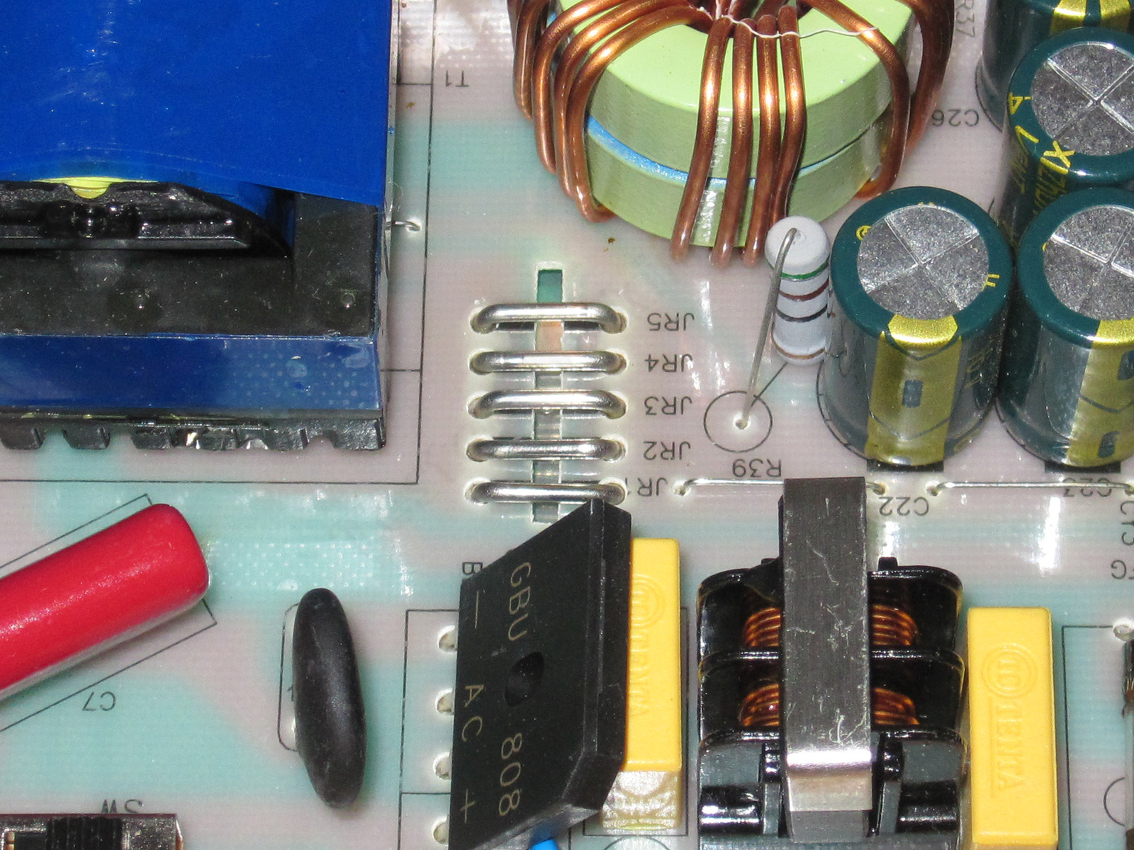
There are even five current-sense resistors here instead of four, so by my calculations the protection should trip at around 50+ A. Wait, did the Chinese take a 50 A unit and label it as 40 A?
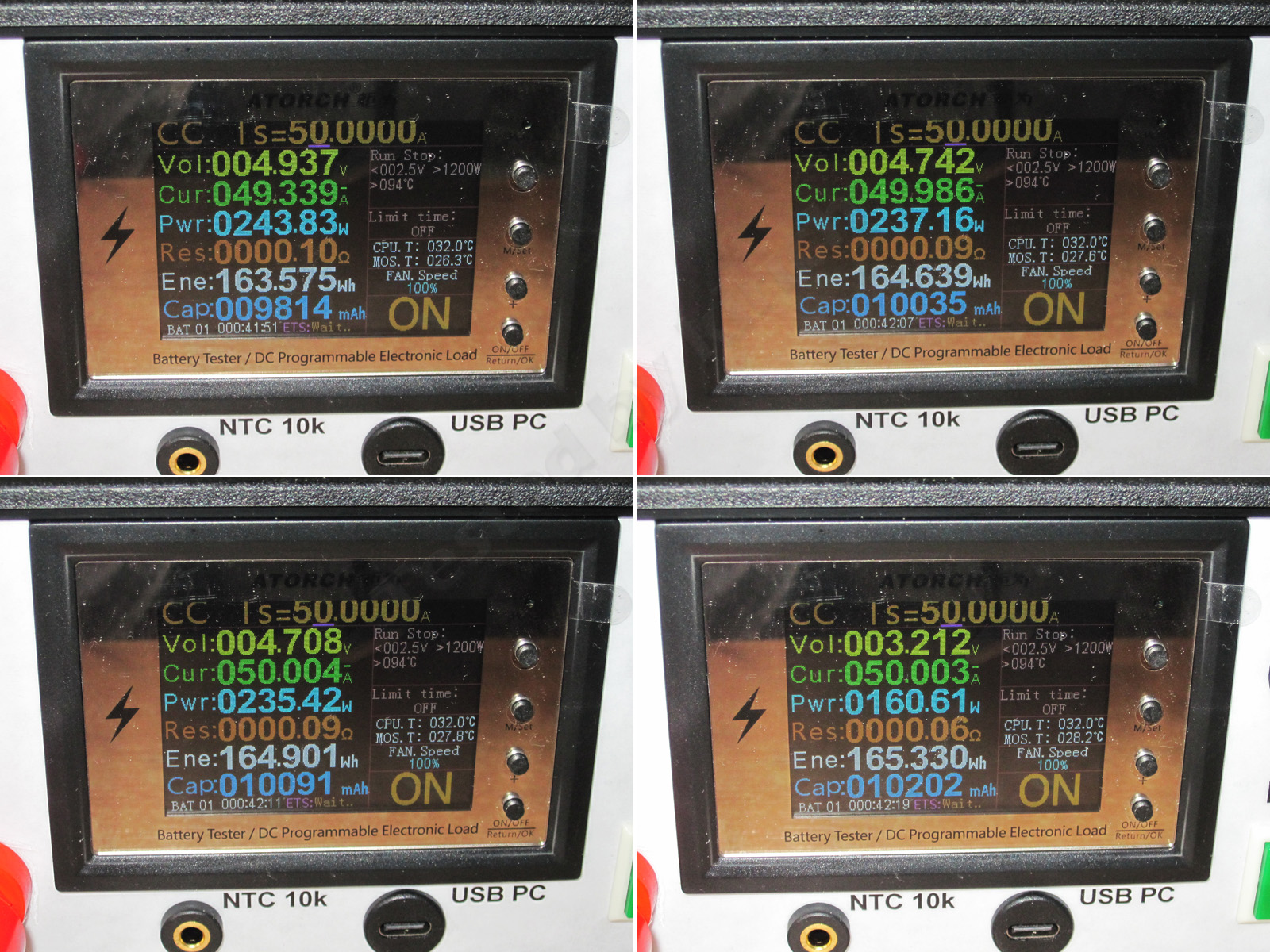
For testing the protection, I used a 50 A load. I could have used a 120 A one, of course, but it would have been very inconvenient. I had a feeling 50 A wouldn't be enough, but it worked out.
You can see in the photo how the load current rises. It increases gradually here: the current reached its maximum of 50 A, and only then did the output voltage start to drop.
I suspect I caught it right on the threshold. The current was higher when cold, but dropped as the current-sense resistors warmed up. So the actual current here was probably around 49–49.5 A. That puts this power supply closer to 225 W than 200 W.
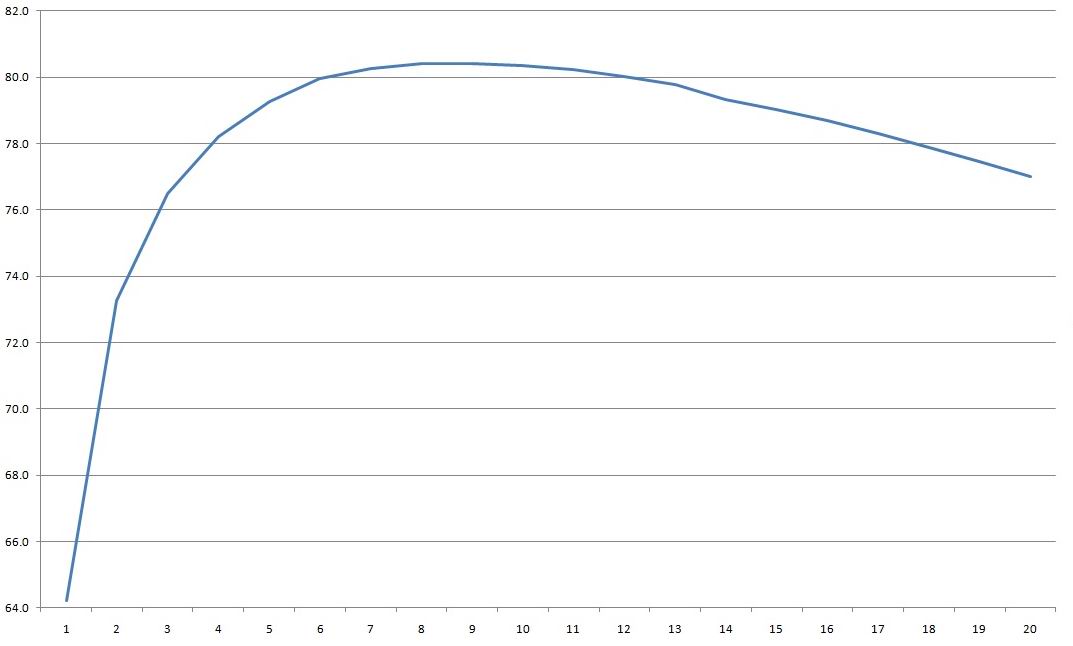
But the efficiency is downright disappointing. I measured it from 2 to 40 A in 2 A increments. At low power levels, I got as little as 56%, though that was probably due to the fan. But even in the middle of the range, efficiency was only 77.5%, compared with 80% for the previous unit—possibly because of the inductor and the fan.
Ripple with no load and at currents of 13, 26, and 40 A.
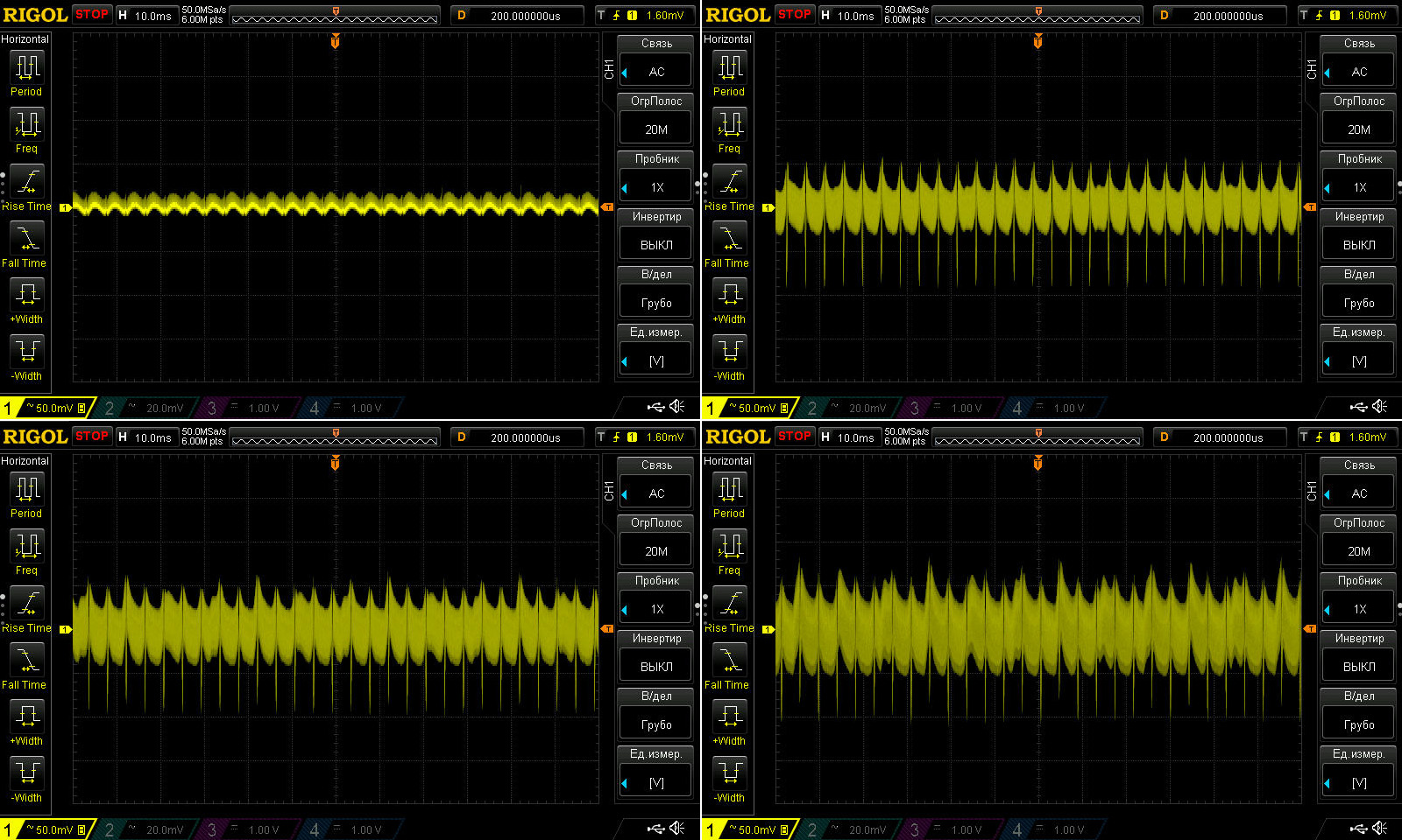
The results here are clearly better than with the previous unit—noticeably so. Even at 40 A, ripple is around 60–70 mV, versus 160–170 mV on the previous one. The capacitors’ lower ESR makes a big difference.
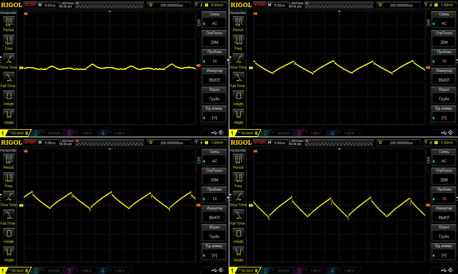
Ripple is noticeably lower even at 100 Hz. Its shape has changed too, but the 100 Hz spikes—and the overall ripple level—are both much lower.
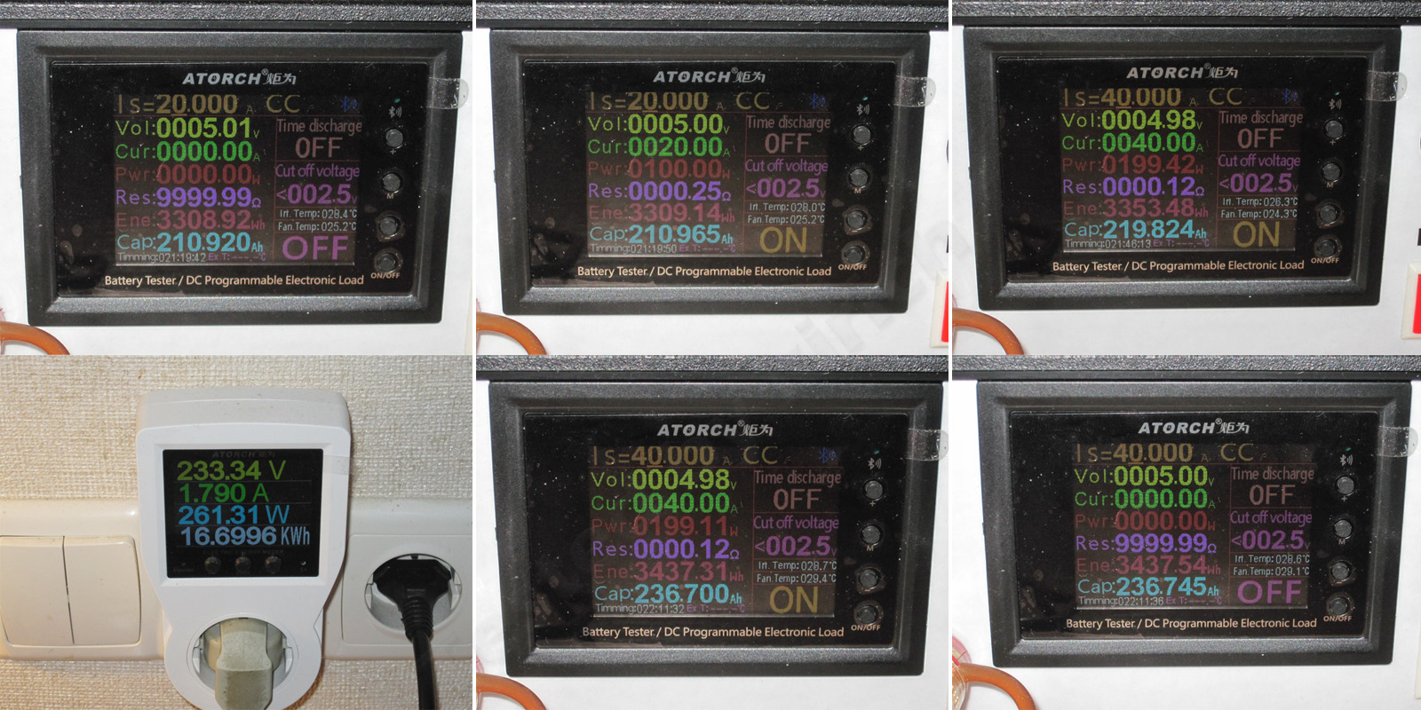
I used a somewhat simplified program for the thermal test here,
First I loaded it to 20 A, then ran it at 40 A for almost half an hour.
1. No load: 5.01 V
2. At 20 A, it dropped to 5 V
3. With the unit warmed up and running at 40 A, it dropped to 4.98 V.
4. It drew 261 W from the mains.
5. With the unit hot and running at 40 A, the output was 4.98 V. After removing the load, the voltage rose to 5 V.
The results are again close to ideal: we lose 10 mV as the unit warms up, and another 20 mV due to the load.
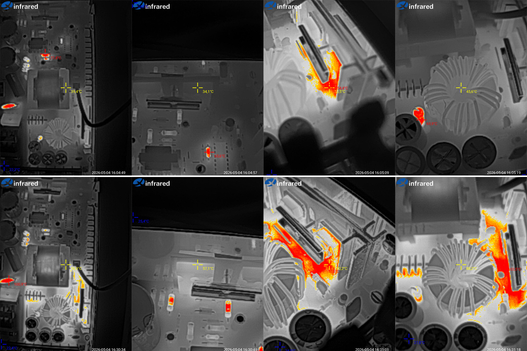
Temperatures.
At 20 A: transformer 40°C, transistors 34°C, diodes 54°C, and inductor 46°C—simply ideal.
At 40 A: transformer 57°C, transistors 57°C, diodes 102°C, inductor 80°C.
The only real criticism here is the diodes. To be fair, the case wasn’t fully closed, since I had to remove the cover during the test. Even so, the temperatures are much better than on the previous unit, which is why I think this is more like a 225 W, 45 A power supply than a 200 W, 40 A one.
Conclusions
10 W - Surprisingly good power supply. It really delivers up to 15 W, has decent components, and is neatly assembled. It could use a lower protection current and an output filter, but it’s perfectly usable as is.
25 W - I’d say it’s decent overall, but in practice it’s good for 4 A continuous at most. Beyond that, the diodes overheat.
40 W - Very good. It has adequate input capacitance, the main components don’t overheat, it easily handles 10 A, and the protection kicks in at 11.5 A, which is fine. Ripple is low too. A more capable output inductor would make it excellent; then it could handle 10 A continuously.
100 W - A decent 75 W power supply, both in terms of build quality and test results, but it can’t deliver 100 W. The output inductor overheats, and the heat-spreader design isn’t great either.
150 W - The results are essentially similar to the 100 W model: actual power is 75% of the rated value, and ripple is fine, but the inductor overheats again, and the output diode assembly gets noticeably hot. I suspect the diode assembly was heating up mainly because of the poor design.
200 W passive - Déjà vu: the same 75% of rated power, but now everything heats up at 100%—the transformer, diode assemblies, and inductor. In other words, the power supply simply can’t handle its rated power, and there’s no way to fix it with a few simple tweaks. Add a heatsink and increase the inductor size, and the transformer will still overheat, so an upgrade isn’t worth it. Ripple is mediocre too, so you’d also have to replace the capacitors, both on the input and output. The one thing I did like was the excellent voltage regulation.
200 W active - This one is a completely different story. It easily handles its rated 200 W, and I think it could deliver more—225–230 W, for example. Ripple and temperatures are both fine, and the construction is better too: instead of a heat-spreader plate, it has a proper heatsink. But they skimped on the input capacitors, so increasing their capacitance would make sense. And the thing I dislike most is the fan—or rather, the cheap Chinese fan. If it had a Sunon fan, I wouldn’t have a word to say, apart from the dust issue. As it is, it’s a mixed bag and suitable only for clean environments.
In short, only the 10 W, 40 W, and actively cooled 200 W models passed the tests completely. The 25 W model has overheating diodes; the 100 W, 150 W, and passively cooled 200 W models deliver only 75% of their rated power. There are also issues with the design and components. That said, all the units are assembled quite neatly.
That’s all for today. Thanks for reading. I really hope you found this useful, and thanks to Vitaly for sending the samples for testing.
This page was found when searching for:
усилитель двухполярный
усилитель двухполярный
This model is included in the summary table: Comparison of power supplies: ripple, efficiency, and temperature rise
The figures from this review are in the measurement database: Power supplies
Calculate manuallyAll calculators
Discounted products
You may be interested in


Discounted products
Support the project
All the content on the site and the advice are free, but we’d be grateful for your support of the project and the channel!
Comments9
Discuss on the forumHave a question or some experience to share? Discuss the article with the author and readers: the forum is a convenient place to share schematics and photos.
Go to the forumOnly registered readers can comment. It takes a minute to sign up, and you can log in with the same account you use on the forum.
Log inRegister
Comments are published in their original language.