
Comprehensive review of 14 power supplies from the new revision
I've written several times that we're not just trying to find decent power supplies among all the Chinese junk—we also send the factory recommendations for improvements when a power supply has no critical issues and is reasonably priced.
Most of the models here today are, in fact, ones sent after being modified to meet our requests.
A reminder: to keep up with new blog posts, I recommend following me on Instagram. I'll post notifications about all new posts there, and might also write about something interesting from time to time: link to my account
You can also subscribe to updates and new articles on the Telegram channel - https://t.me/KirichBlog Just a note: discussion of reviews and articles is enabled on the channel, and you can also just chat. I recommend it.
Just to put things in perspective, there are several ways to get something of decent quality at a reasonable price.
1. Search through dozens of factories and hundreds of power supplies.
2. Find a few factories willing to make power supplies according to our improvement recommendations.
3. Design and manufacture the power supplies ourselves.
The first option is mostly a dead end: first, it's a lot of work, and second, manufacturers like these often change the internals on the fly.
The second option is much more worthwhile, especially if the factory is genuinely interested in working with us and has competent engineers.
The third option is more expensive, but even more predictable. It's still under consideration.
To get ahead of myself, this review turned out to be very long as it is, so I didn't measure efficiency. But I'll say that this was one of the parameters we were trying to improve. The point is that efficiency is directly related to heat generation, which I think is obvious.
But what affects efficiency? A whole lot of things.
The input capacitor's capacitance—not much, but it still matters.
The combination of the PWM controller and high-voltage transistor.
The snubber circuit design and transformer quality; sometimes a poor design can undo all the improvements.
The output diode—ideally, a synchronous rectifier. This can give a noticeable increase in efficiency.
The output capacitors. ESR is the main factor here. I experimented with this once, and yes, replacing regular capacitors with polymer ones also increases efficiency a little, while reducing ripple and improving reliability.
The output inductor that filters ripple. It's best to choose one with plenty of current headroom, so its DC resistance has less effect.
We experimented with many of these things.
Today's review covers 4 24 V power supplies and 10 12 V power supplies.
I'll start with the 24 V versions. These are also pre-production samples, but I hadn't seen them before, so I'll send the manufacturer a report on them.
Two power supplies are marked 24 V, 2 A, in the "adapter" form factor, and two are desktop models. There are three in the first photo because I initially thought the two adapters were identical.
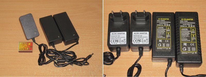
1. The model marked 24 V, 2 A. The case is held together with clips, which is nice. In fact, all the power supplies in this review have clip-together cases.
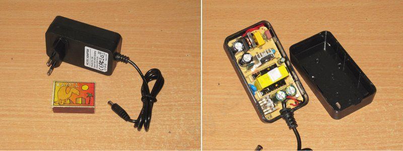
It looks pretty good: heatsinks on the transistor and diode assembly, an input filter, and a small output inductor. Overall, quite acceptable.
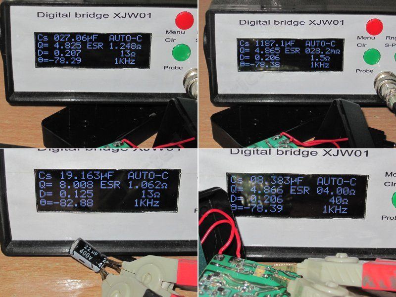
The only odd thing I noticed right away was that there are two input capacitors, 10 and 22 µF, but both are rated for 400 V and are exactly the same size...
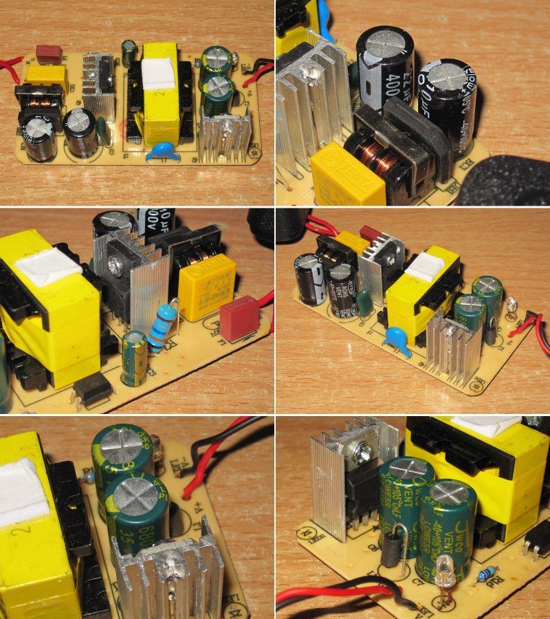
No concerns about electrical safety: the clearance between the primary and secondary sides is sufficient, there's a Y-rated capacitor between the windings, and there are spark gaps under the input inductor.
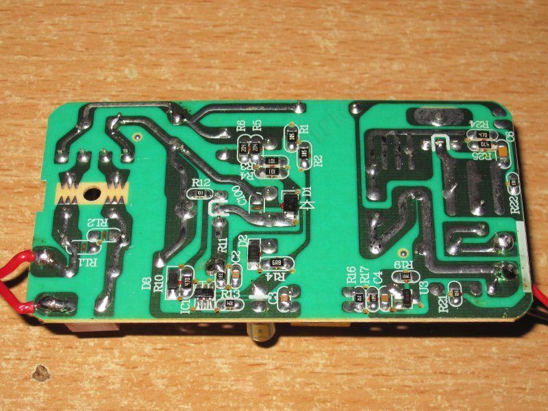
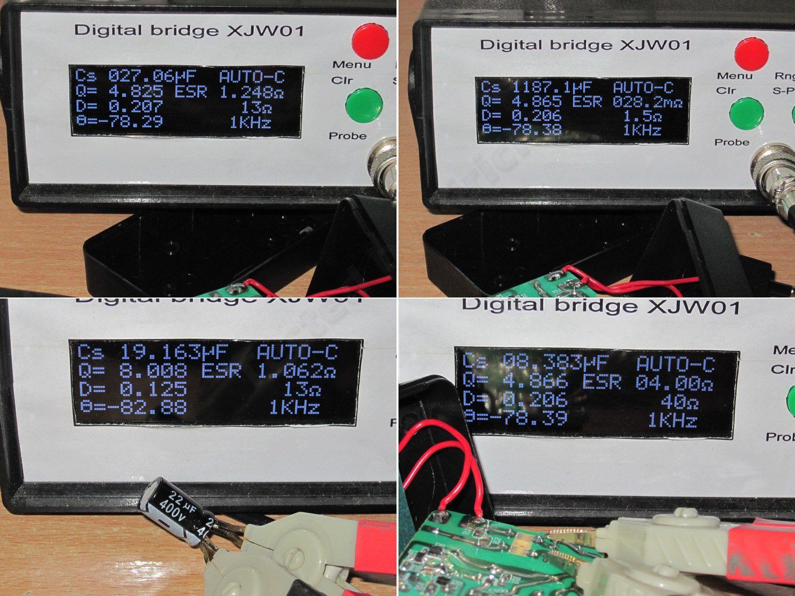
The input capacitors have a total capacitance of 27 µF, which is a bit low for 48 W. On the output there are two 680 µF, 35 V capacitors; their measured combined capacitance is about 1200 µF, which is acceptable.
Remember I mentioned the odd input capacitors? I suspected they might actually be a pair of 15 µF capacitors with different markings, but no—the capacitance of one really is close to 22 µF and the other's close to 10 µF, despite them being the same size. I have doubts that the 22 µF capacitor is actually rated for 400 V, so we'll follow up on this with the factory.
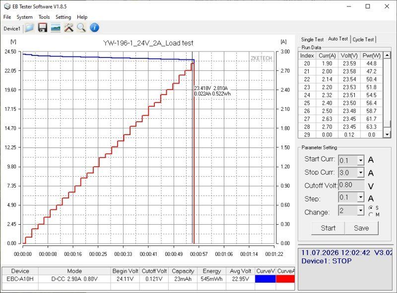
The protection trips at around 2.8 A, which is far too high for this power supply. It's entirely possible to load it to 2.5 A and have it fail from overheating. We'll address this too.
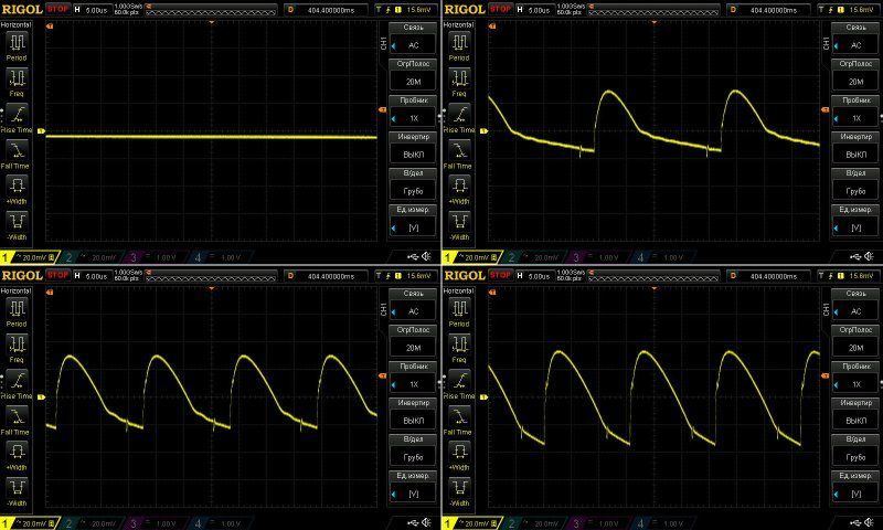
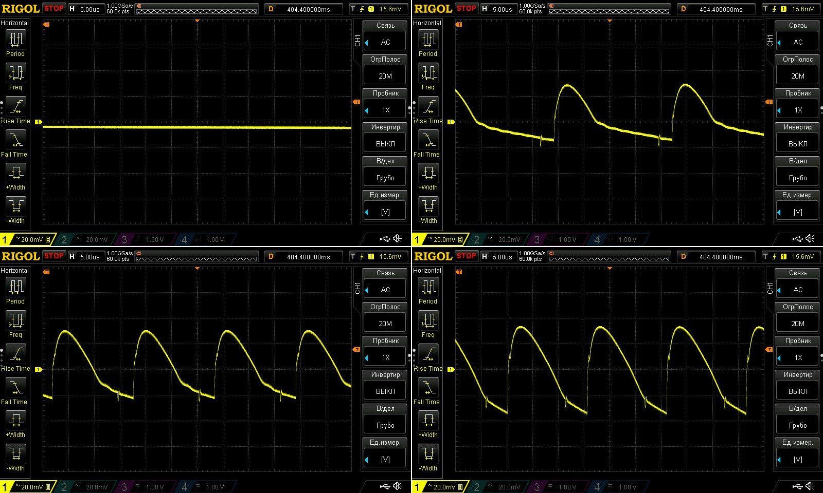
Ripple is pretty good: around 70 mV at high frequency. That's especially good considering this is a 24 V power supply.
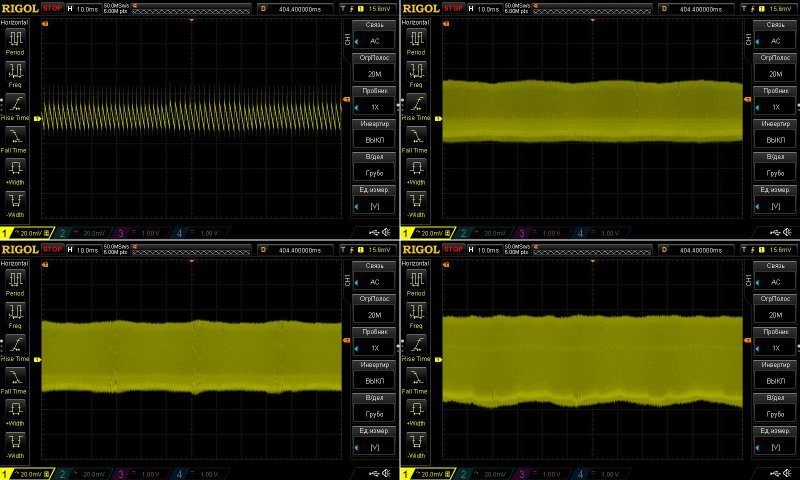
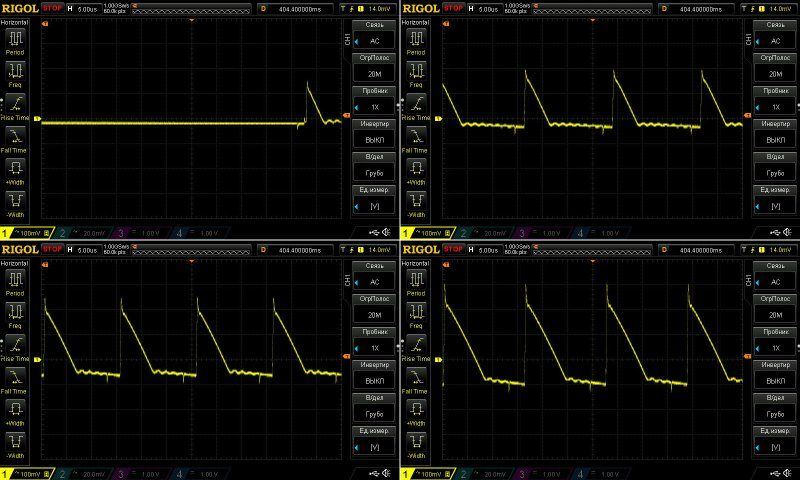
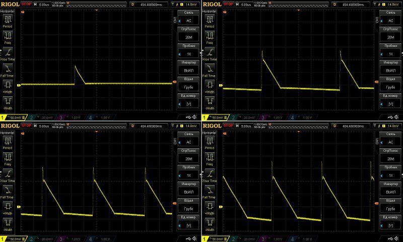
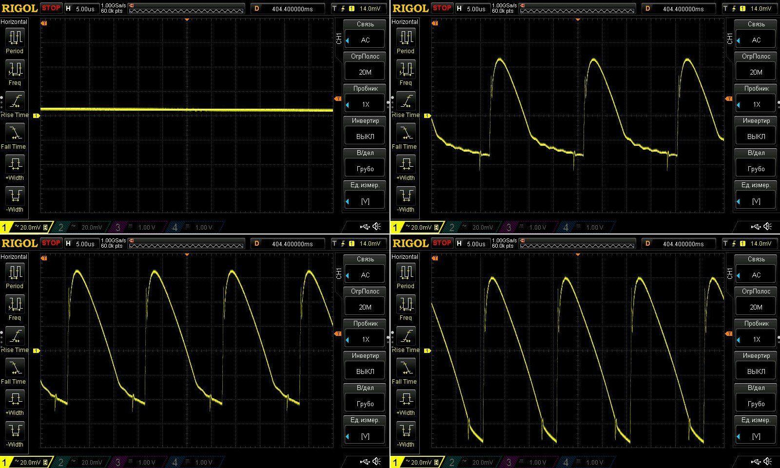
Here and below, ripple is measured under these conditions: no load, then at 33, 66, and 100% load; the probe input has two capacitors in parallel, 1 and 0.1 µF; measurements are taken directly at the PCB output pads, i.e. Most of the high-frequency ripple won't make it to the load.
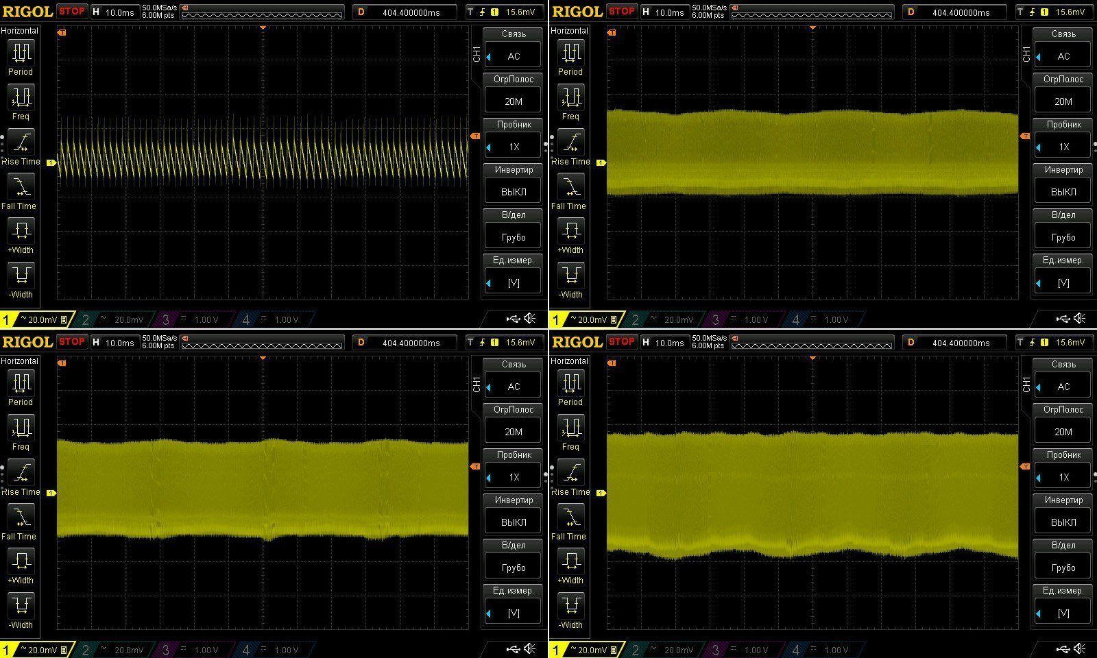
I also have no complaints about the 100 Hz ripple, especially considering that the input capacitors are below their rated capacitance.
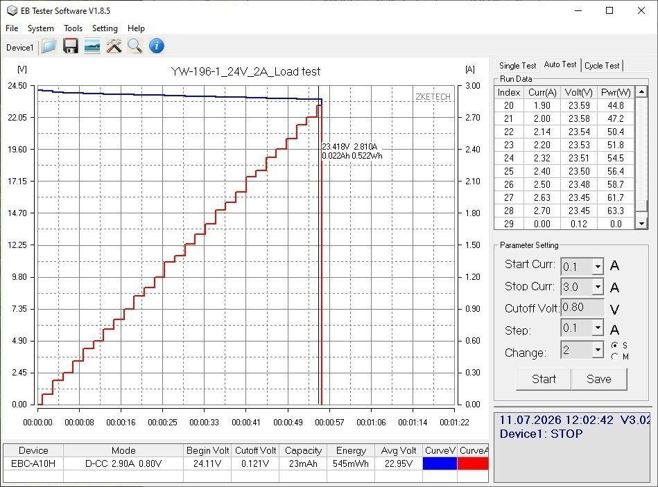
The thermal test was carried out in three stages, at load currents of 1, 1.5, and 2 A. Even though the voltage was measured after the output cable, it remained quite stable.
The voltage has a slight positive temperature coefficient. At the bottom of the screenshot on the right is the no-load voltage at the start of the test: 24.11 V. At the top right is the no-load voltage after warm-up: 24.15 V.
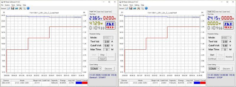
And now for the most important part: the temperatures.
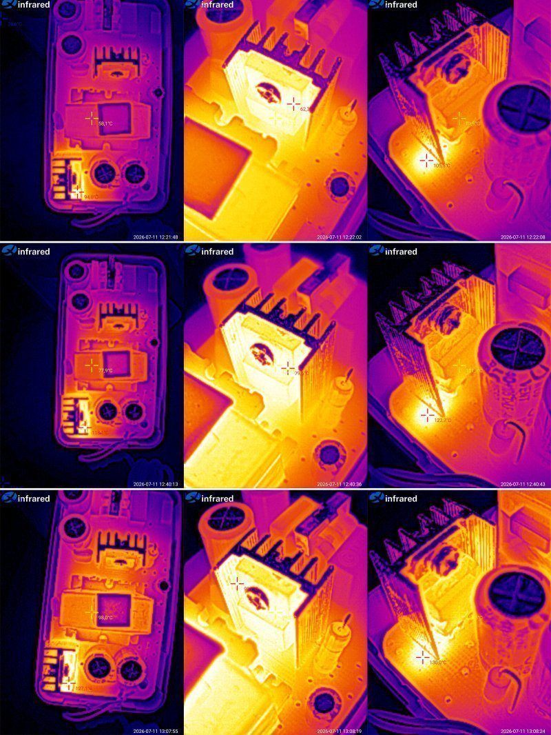
At 1 A: transformer 58°C, transistor 62°C, output diode assembly 82°C.
At 1.5 A: transformer 78°C, transistor 80°C, diode assembly 101°C.
At 2 A: transformer 98°C, transistor 99°C, diode assembly 116°C.
Personally, I think that in its current form, the continuous output current should be no more than 1.5 A (36 W). Beyond that, the output diode assembly overheats. The transformer and transistor can handle an output current of 2 A, but with very little headroom.
I should also point out that the snubber under the output diode assembly gets noticeably hot. You can see that the board in this area heats up to 130°C. I think that if this issue is addressed (by recalculating the snubber values and moving it a little farther away), the diode assembly temperature will drop.
Logically, this should be the more powerful version, but there's a catch.
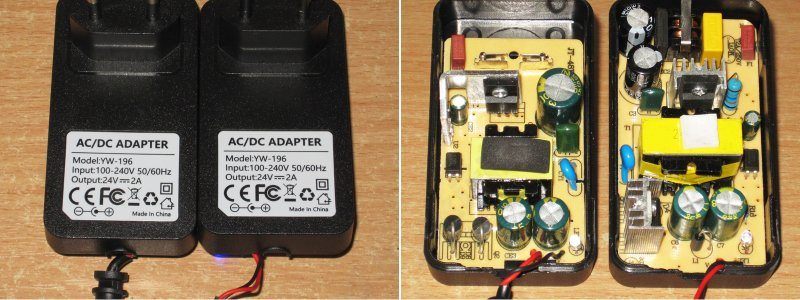
In the photo above, I showed that I received two power supplies that looked absolutely identical, and even thought the manufacturer had simply sent two units for testing. What's more, I asked Vitaly about it—he's the one who sent me all these power supplies.
But in the end, taking them apart cleared things up: the power supplies are identical only on the outside; inside, they're completely different.
The second test unit is on the left; the one I showed above is on the right.
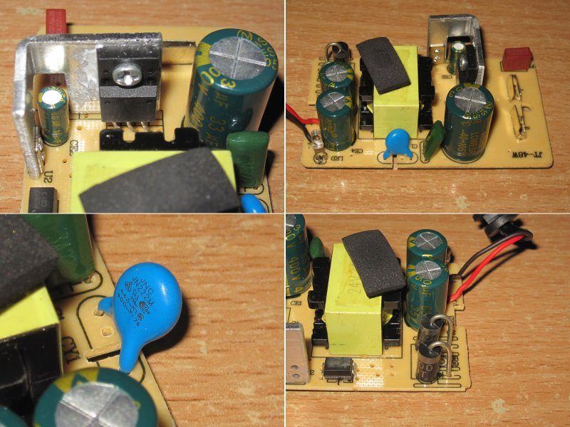
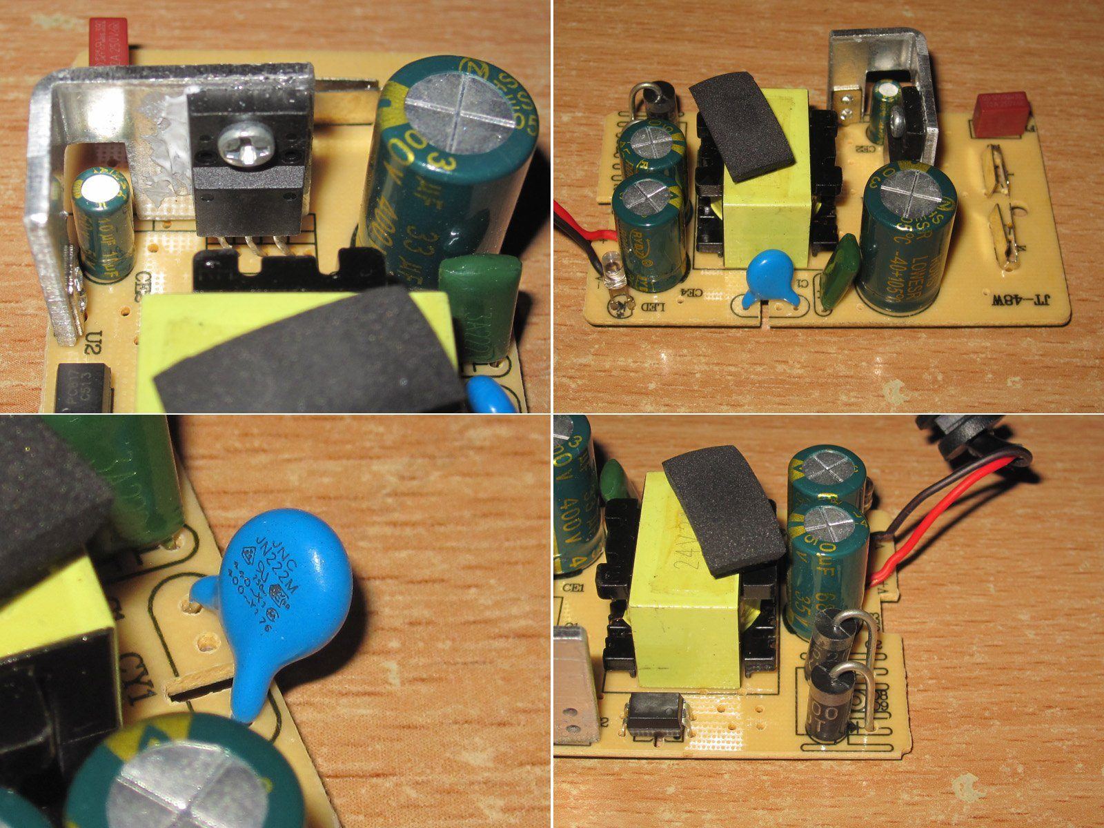
The cost-cutting is impossible to miss; it's coming out of every seam. There's no input filter, the transformer is about half the size, and the output diodes are standard ones rather than an assembly mounted on a heatsink.
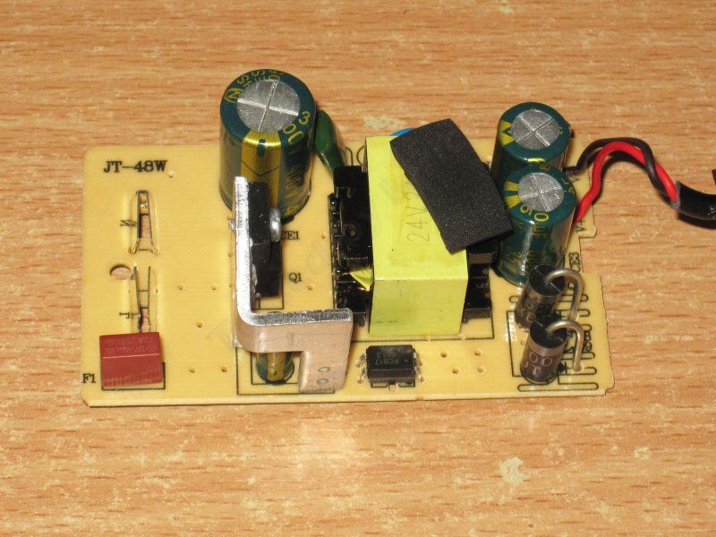
The transistor is installed at an odd angle, and the PWM controller capacitor is right up against the heatsink. The input capacitor is at least 33 µF, so that's just about acceptable.
They used the correct interwinding capacitor and even cut a slot underneath it. On the output side, as with the previous model, there are a couple of 680 µF, 35 V capacitors.
So, basically, it already looks like a budget version of a decent power supply. You can tell right away that it definitely won't deliver as much power as the previous one.
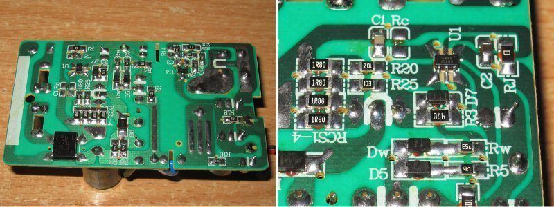
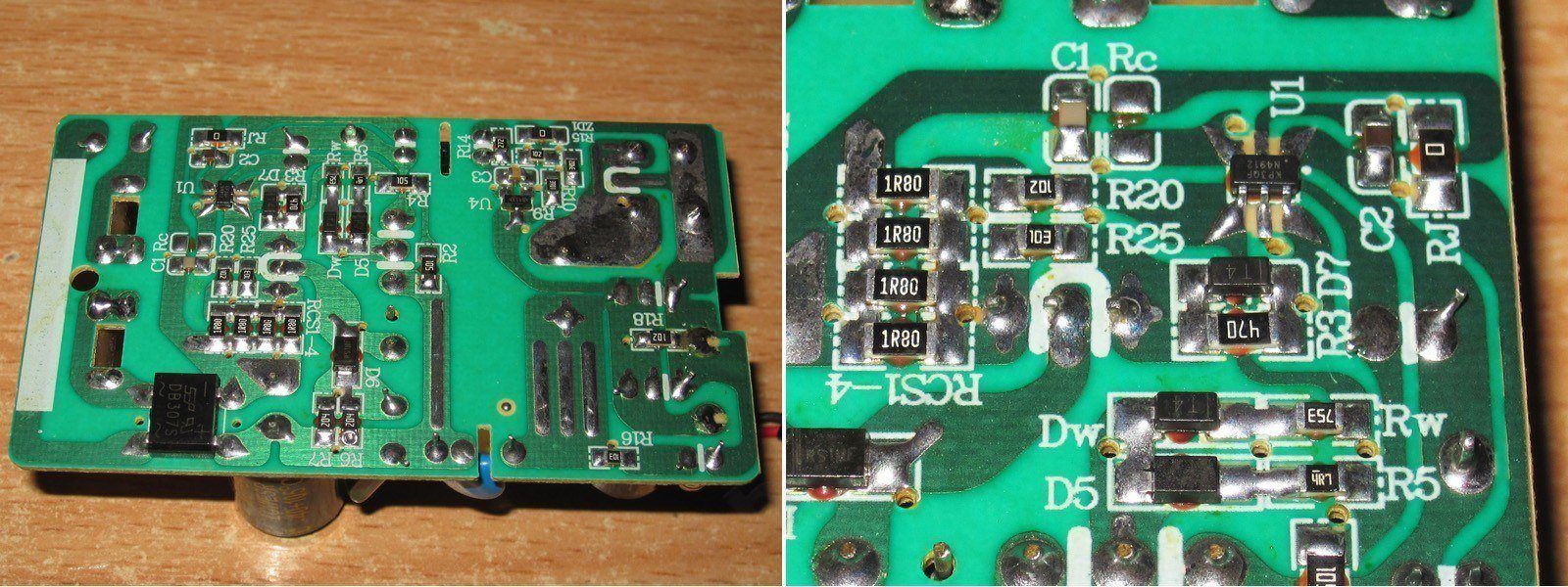
That said, I have no complaints about the circuit board. The soldering is neat, and there are safety slots.
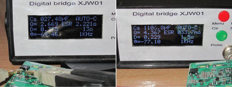
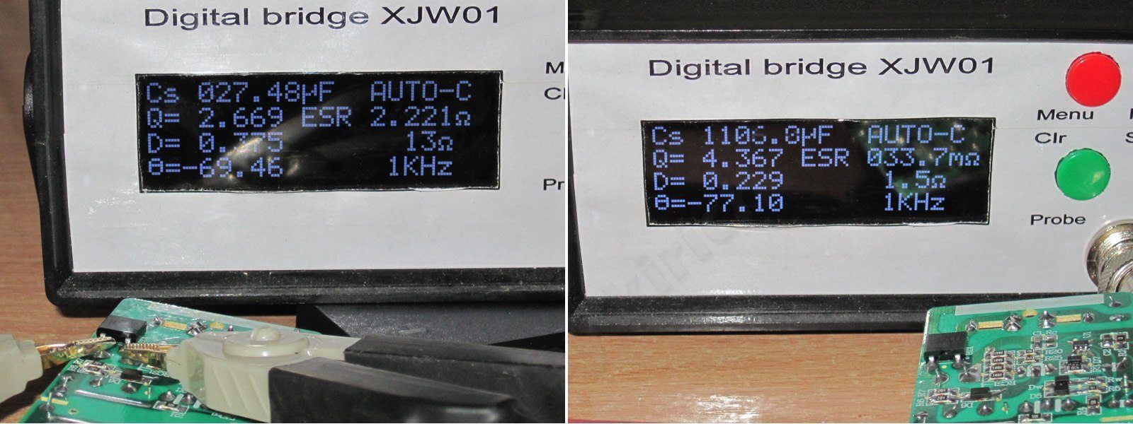
The input and output capacitances are more or less the same as on the previous model.
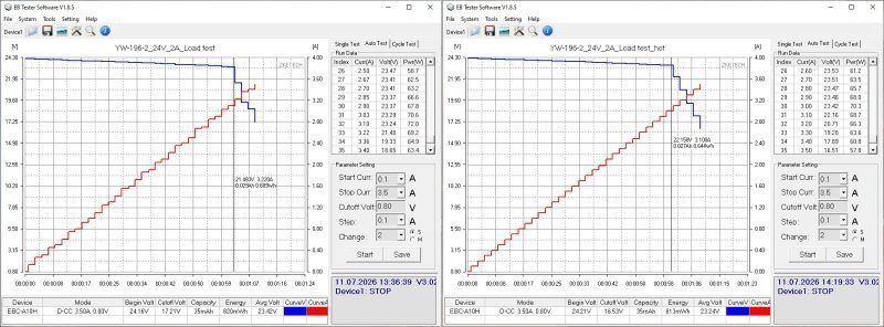
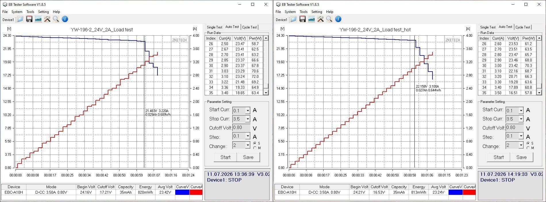
But the overcurrent protection is set to a ridiculous 3.2 A when cold and 3.1 A when hot. Since this power supply is clearly weaker than the previous one, even from the outside, the protection current should be cut roughly in half right away.
The high-frequency ripple is about the same as on the previous unit, around 75–80 mV, not counting the spikes.
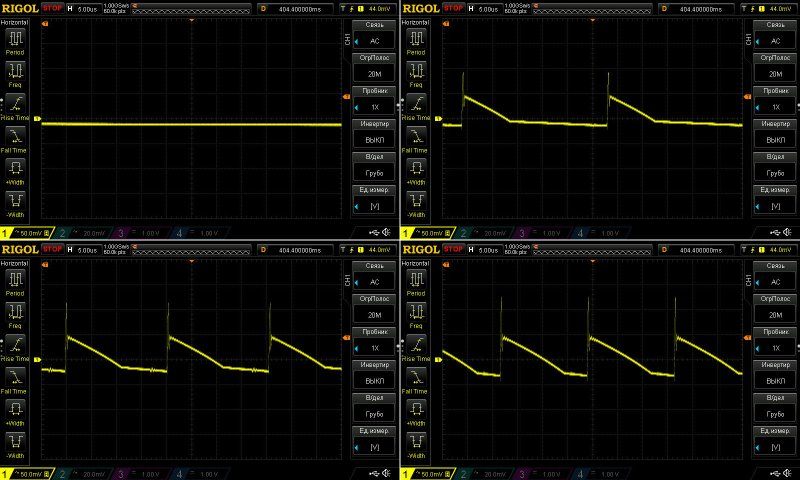
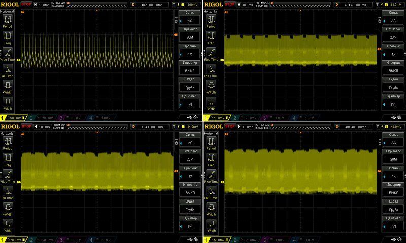
I don't really have any complaints about the 100 Hz ripple, especially considering how clearly budget-oriented this unit is.
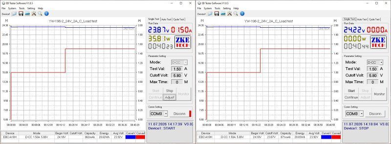
The test was carried out in just two modes, at 1 A and 1.5 A. I think you've already guessed why.
The voltage has a slight positive temperature coefficient, but it's negligible. I also had no complaints about voltage regulation: the entire voltage drop under load was across the output cable.
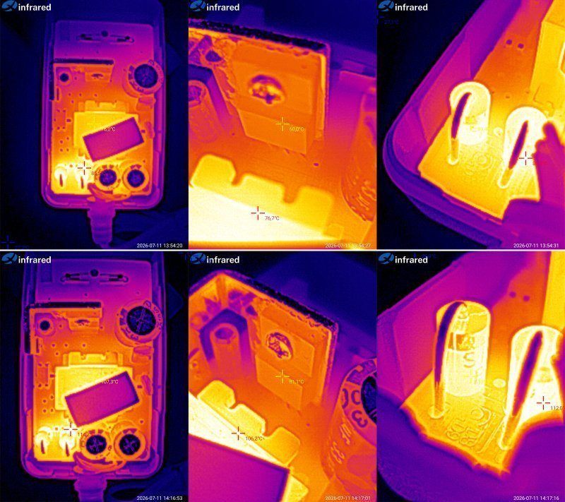
And now for the temperatures.
At 1 A: transformer 76°C, transistor 60°C, output diodes 85°C.
At 1.5 A: transformer 107°C, transistor 81°C, diodes 112°C.
As you can see, the transformer is the weak point. At just 1.5 A, its temperature has already gone over 100°C, which is far too high. I think the power supply's actual output current is 1 A. It can probably handle 1.2 A, but even 1.5 A is too much.
My guess is that this was originally a 2 A power supply, and they simply happened to use a case from the 24 V, 2 A model for the sample. Let's take a closer look.
The third power supply is also 24 V and 2 A, but in a desktop form factor. Cooling is usually better in this type, simply because the case is larger, though there are some caveats.
The thing is, if the cases are the same size, the adapter-style version (the kind that plugs directly into the wall) cools better because it essentially hangs in the air. A desktop unit cools less effectively because it sits on a surface, which restricts airflow. But that's when the cases are roughly the same size.
This case is clearly larger, which should make up for the factors mentioned above.
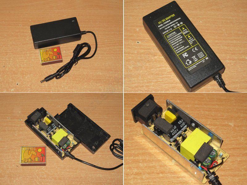
It has an input filter, a thermistor, and a Y capacitor. On the output, though, for some reason there are two 470 µF, 35 V capacitors; the previous units had 680 µF ones. There's also a small inductor to reduce ripple, though one like this is more likely to suppress very short spikes.
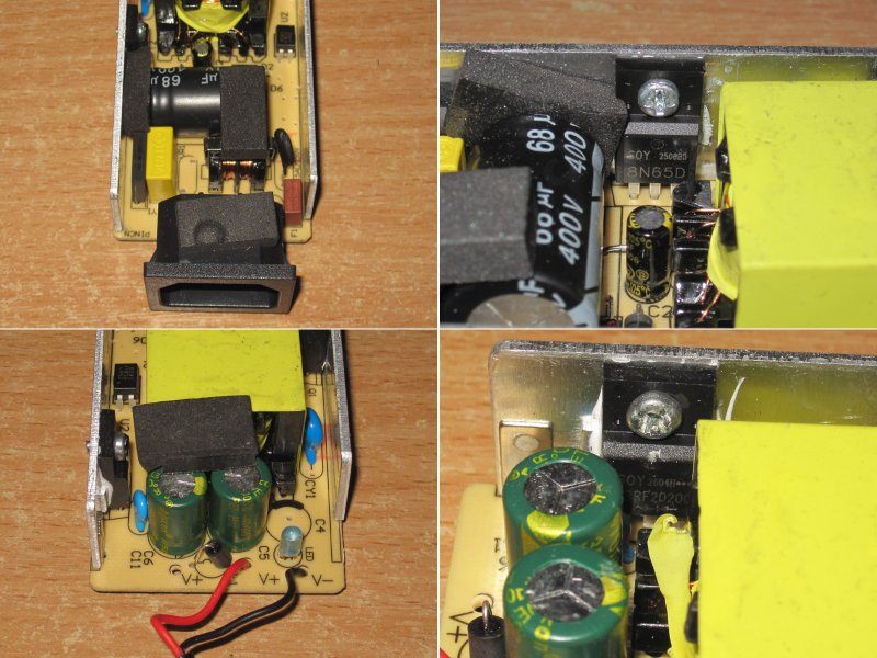
Overall, I have no complaints about the board. The clearance between the primary and secondary sides is sufficient, and the soldering is neat too—well, almost.
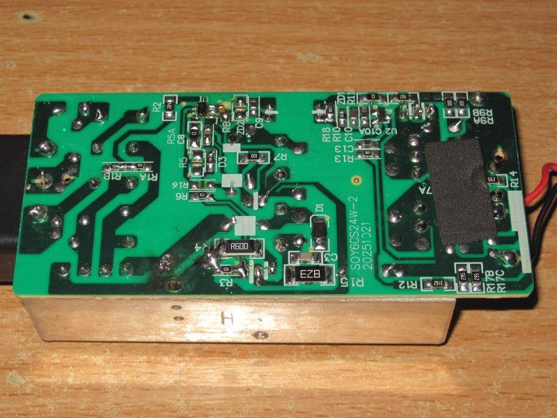
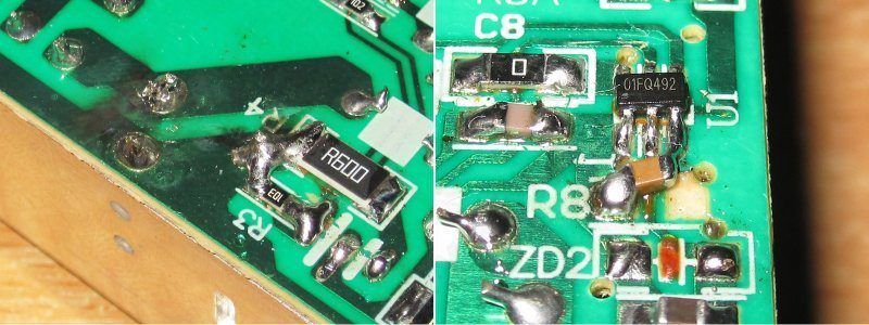
But then I noticed a few oddities: messy soldering on the shunt, soot around the capacitor leads, and a capacitor near the PWM controller soldered on crooked.
But actually, that's normal. The soot probably came from shorting the input capacitor, and the shunt was being adjusted to find the right value—in other words, this is clearly a prototype. None of this will be present in the production version.
And yes, you can tell the factory made a test sample specifically, rather than just grabbing the first suitable unit they could find.
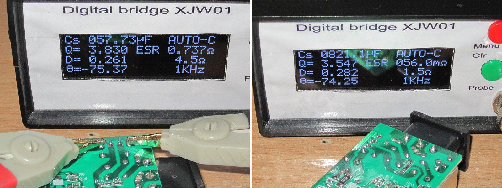
About 58 µF on the input, which is excellent for 48 W. The output has 820 µF; I'd have liked to see more, at least as much as in the previous units, which had two 680 µF capacitors.
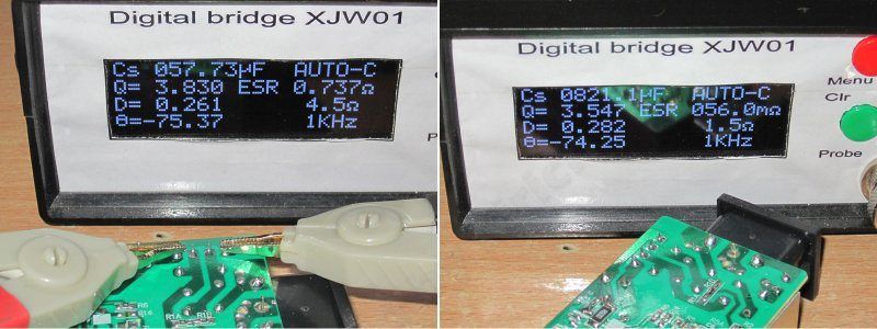
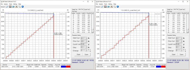
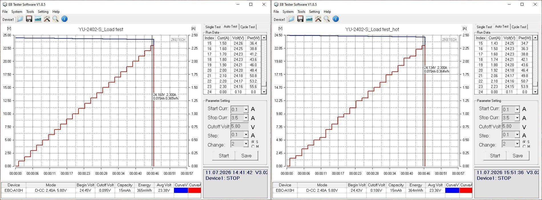
The protection is set correctly, at 2.3 A, and here too you can see that they were experimenting with the shunt.
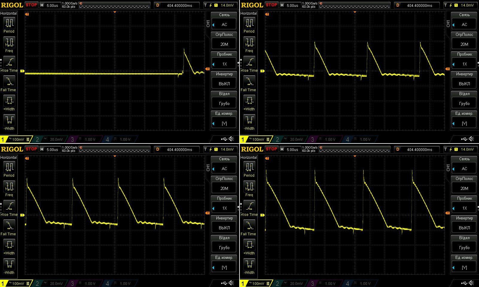
The ripple, though, isn't great. At high frequency and full power, it's around 300–400 mV—not a complete disaster, but I think replacing the output capacitors with higher-capacitance ones and fitting an inductor with higher inductance could cut it by a factor of two. Let's write down the recommendations, then check again.
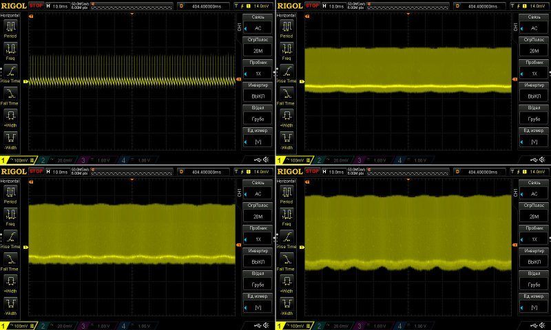
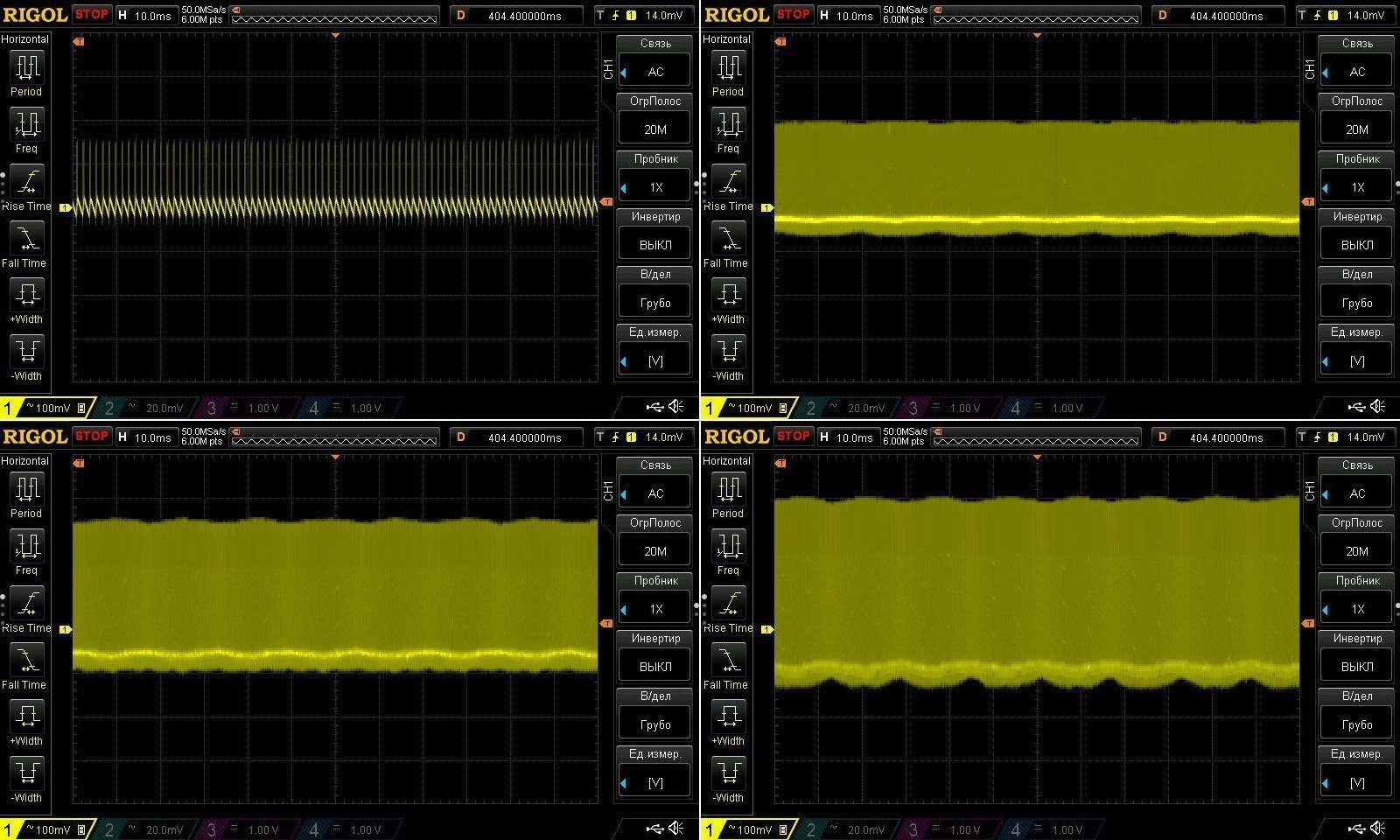
At 100 Hz, everything looks fine, apart from the generally high level.
The test was run at currents of 1, 1.5 and amps. I have no complaints here: the voltage drops under load, but not critically. And as a reminder, this is essentially the voltage drop across the cable. There is some dependence on warm-up, but it is very small, around 30 mV.
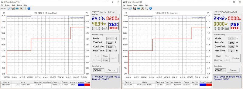
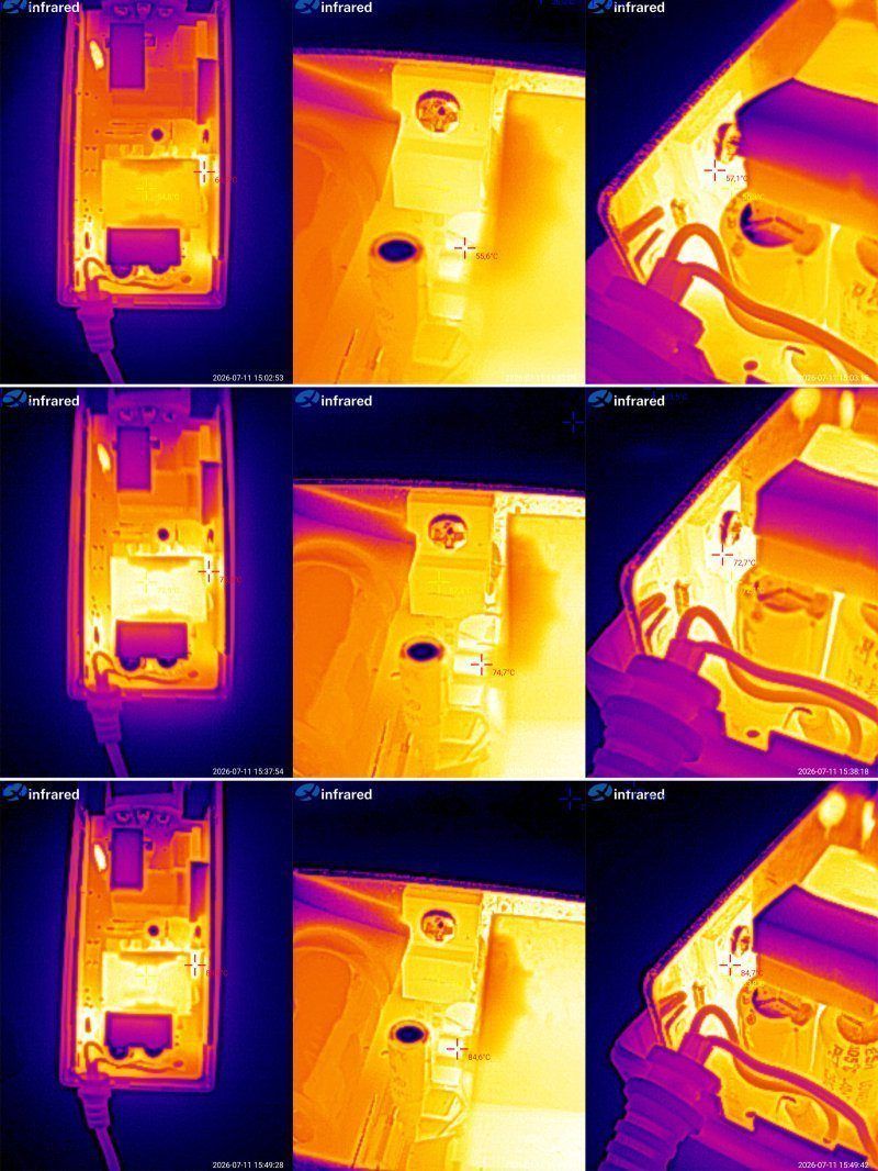
Now for the temperatures.
1 A — transformer 55, transistor 55, diode assembly 57 degrees
1.5 A — transformer 74, transistor 67, diode assembly 73 degrees
2 A — transformer 82 degrees, transistor 78 degrees, diode assembly 85 degrees.
The thermal camera picked out other spots as the hottest objects, while the readings in the center blend into the background and may not be visible. But trust me, they are correct.
In my opinion, these are excellent results. The only real complaint about this power supply is the elevated ripple, but that is relatively easy to fix.
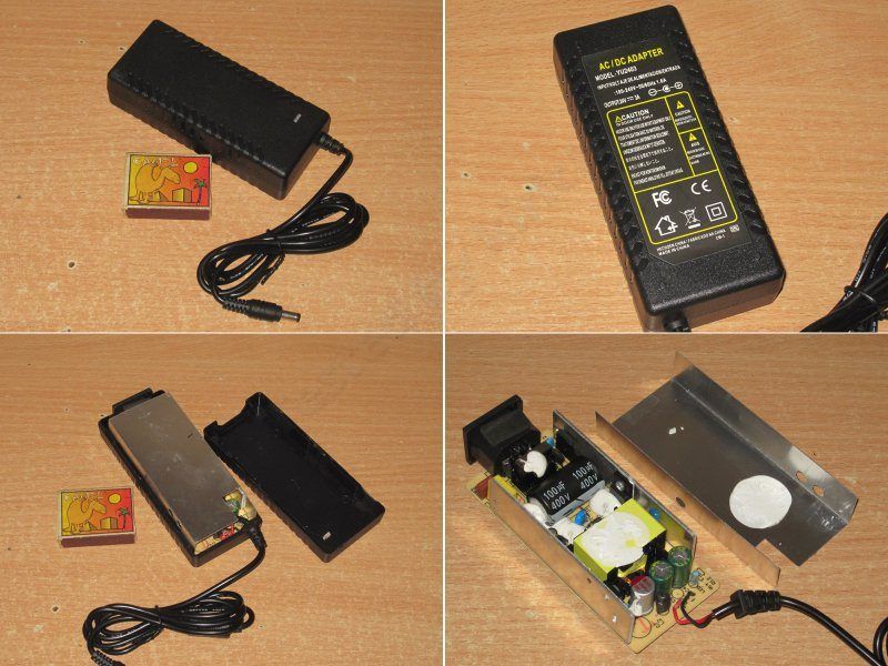
The fourth model is 24 V, 3 A. In my opinion, this one is a little more interesting, especially in terms of its “internals.”
At a glance, it is a standard power supply, but it is worth noting that 24 V at 3 A is 72 W. In terms of the 12 V models, that would be 6 A, which is already quite a lot.
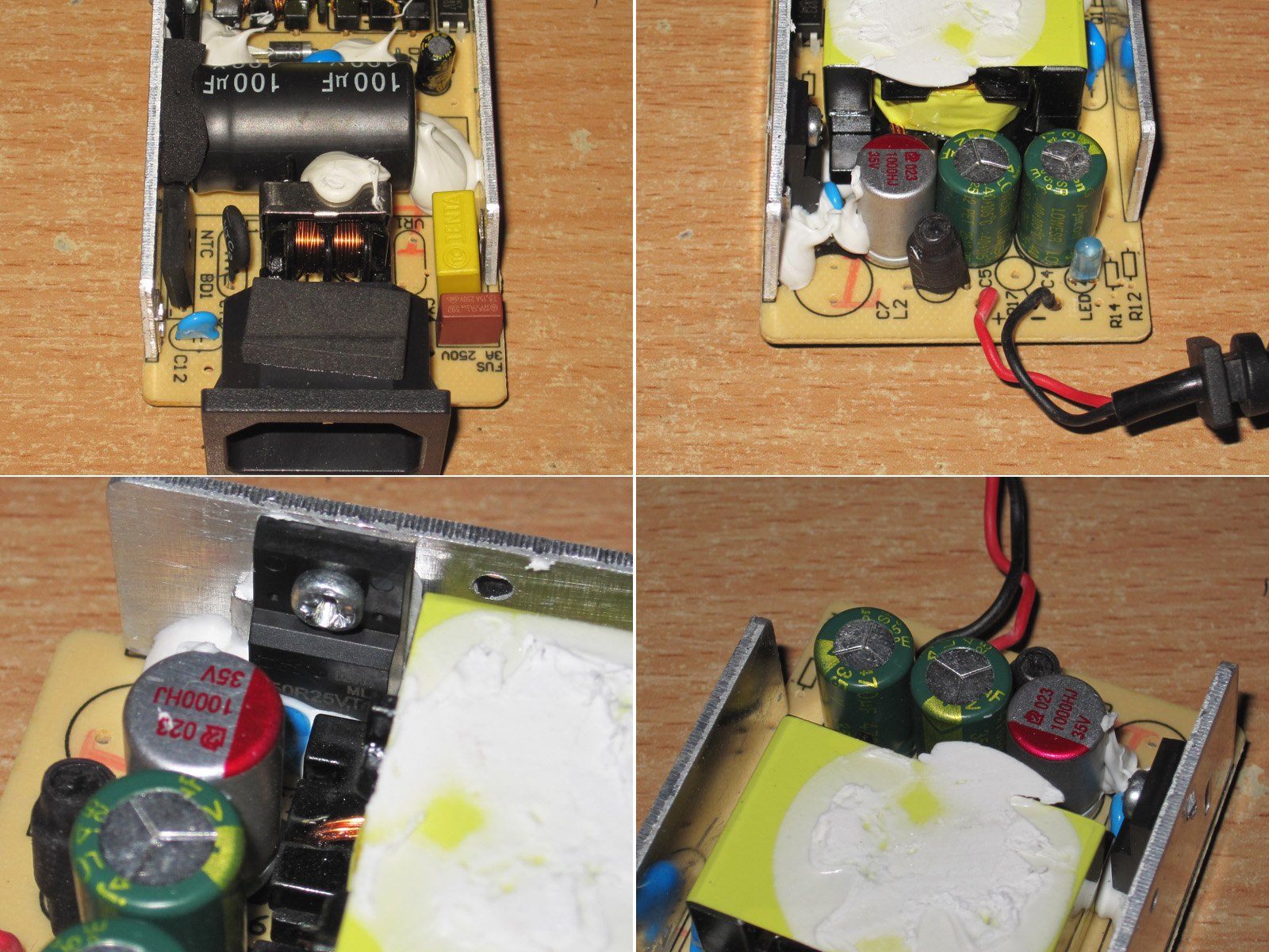
Inside the case there is a steel cover glued to the transformer, which should improve its cooling somewhat. I had to remove it for inspection, though, so the test results may be slightly affected.
The layout is fairly compact, and the components are secured with sealant.
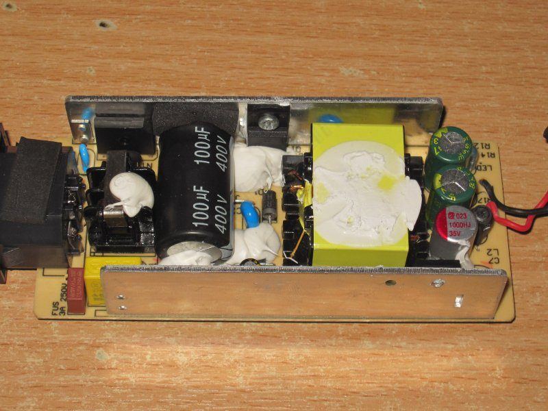
On the input side, there is a filter, a thermistor and a 100 µF capacitor. On the output side, there are three capacitors: one 1000 µF, 35 V polymer capacitor and two standard 470 µF, 35 V capacitors, along with a decent inductor.
As a bonus, they used a synchronous rectifier instead of a diode assembly. I should admit that some time ago I suggested they use chips like these, though that was for the 12 V models. Here, the factory decided to get ahead of the curve, just as it did with the polymer capacitor and inductor.
A Y capacitor is tucked between the transformer and the heatsink.
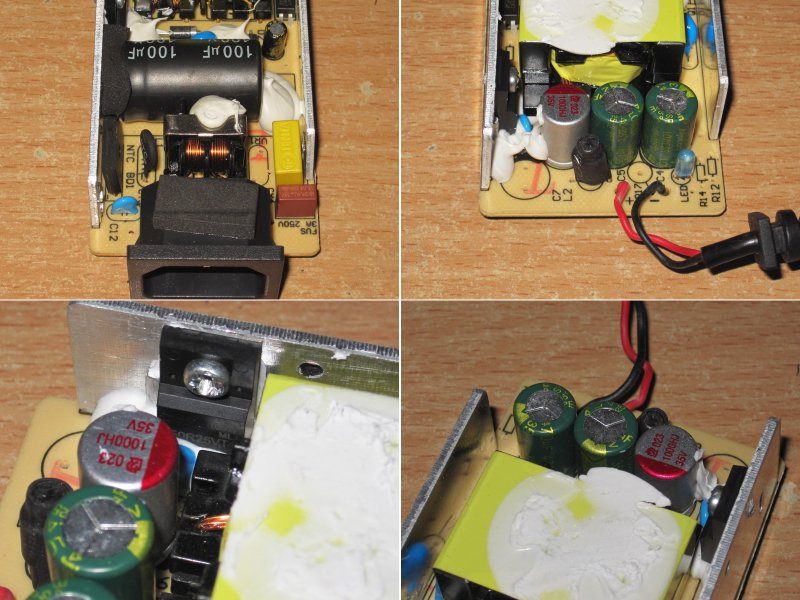
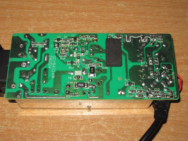
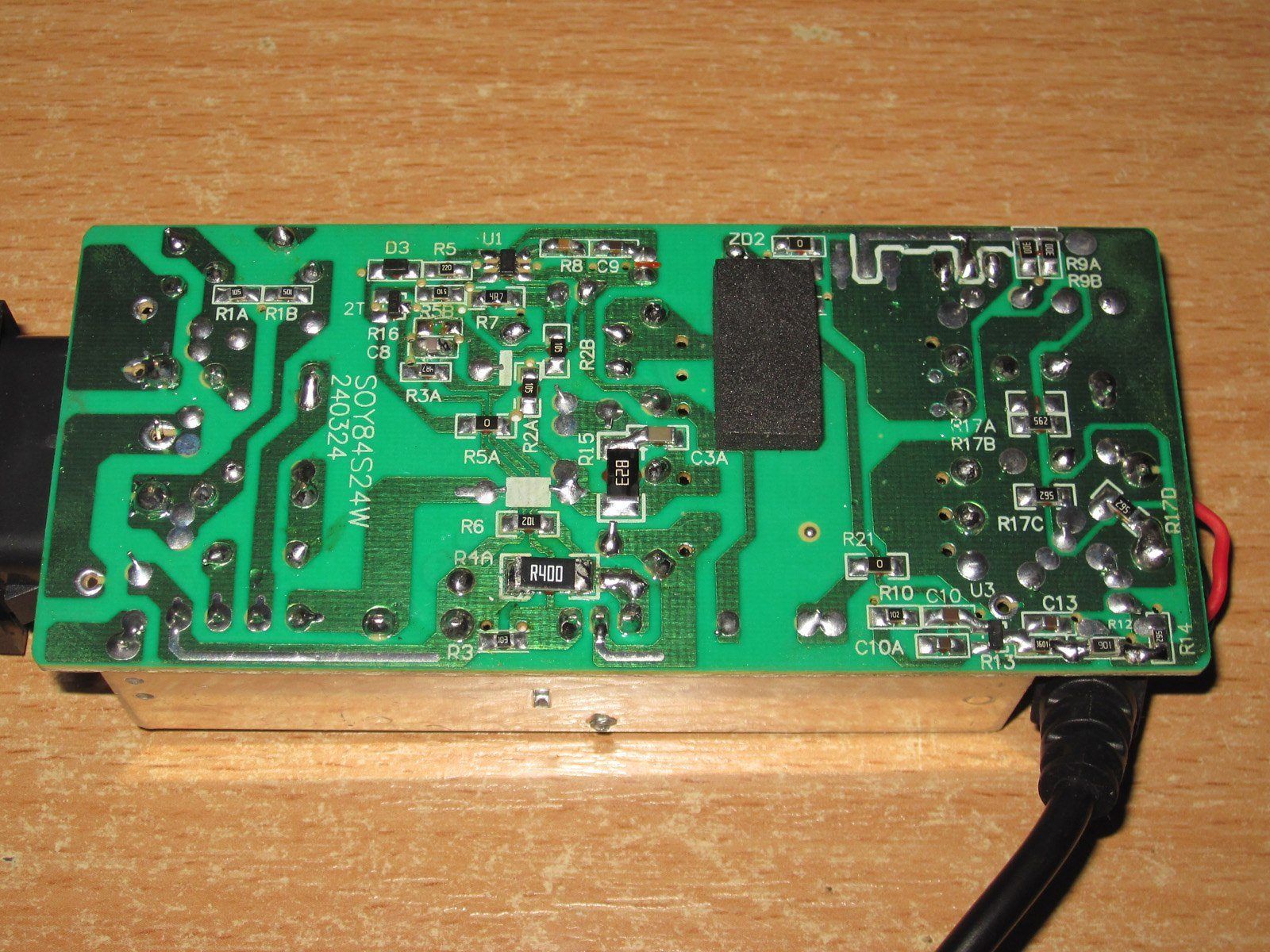
I have no complaints about electrical safety either. I’ll note that the PWM controller’s supply resistors and the discharge resistors are each made up of two resistors in series to improve reliability and safety. The solder points for the heatsink mounts have also been moved farther away from the live traces.
Of course, I still have a few minor comments, but it’s clear that the manufacturer looked at what we recommend for the 12 V models and simply carried those changes over to the 24 V version.
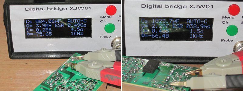
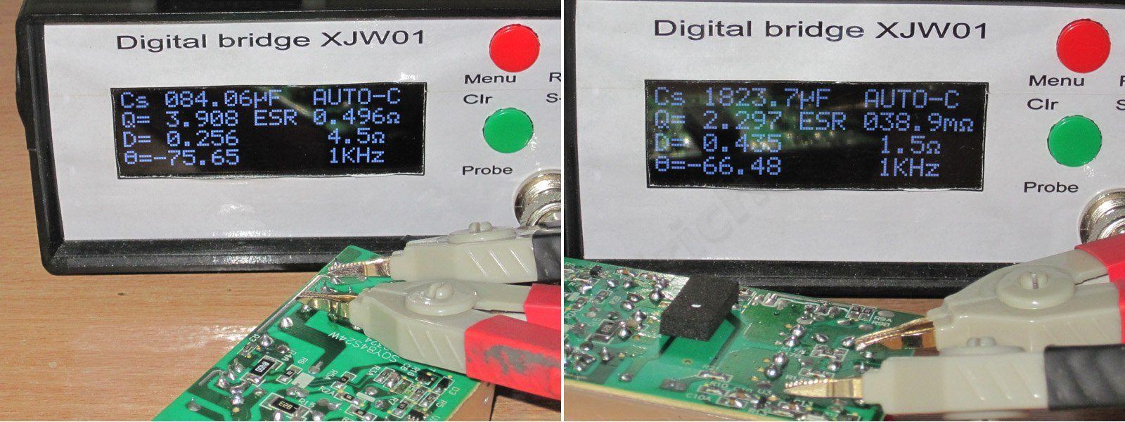
The actual input capacitance is 84 µF, which is still fine for a 72 W power supply. The output capacitance is 1800 µF, though I seem to have chosen the wrong test points, because for some reason the ESR reading came out quite high.
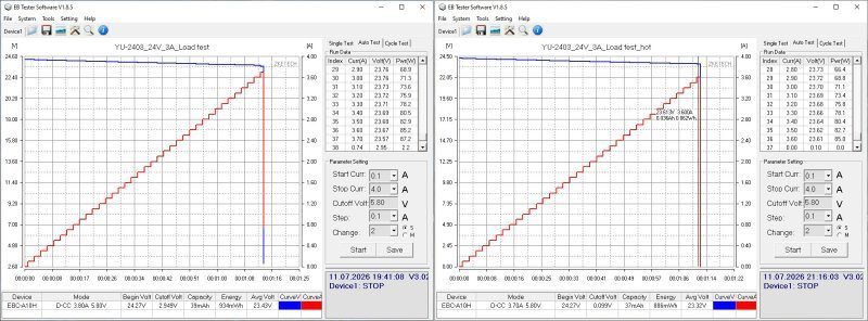
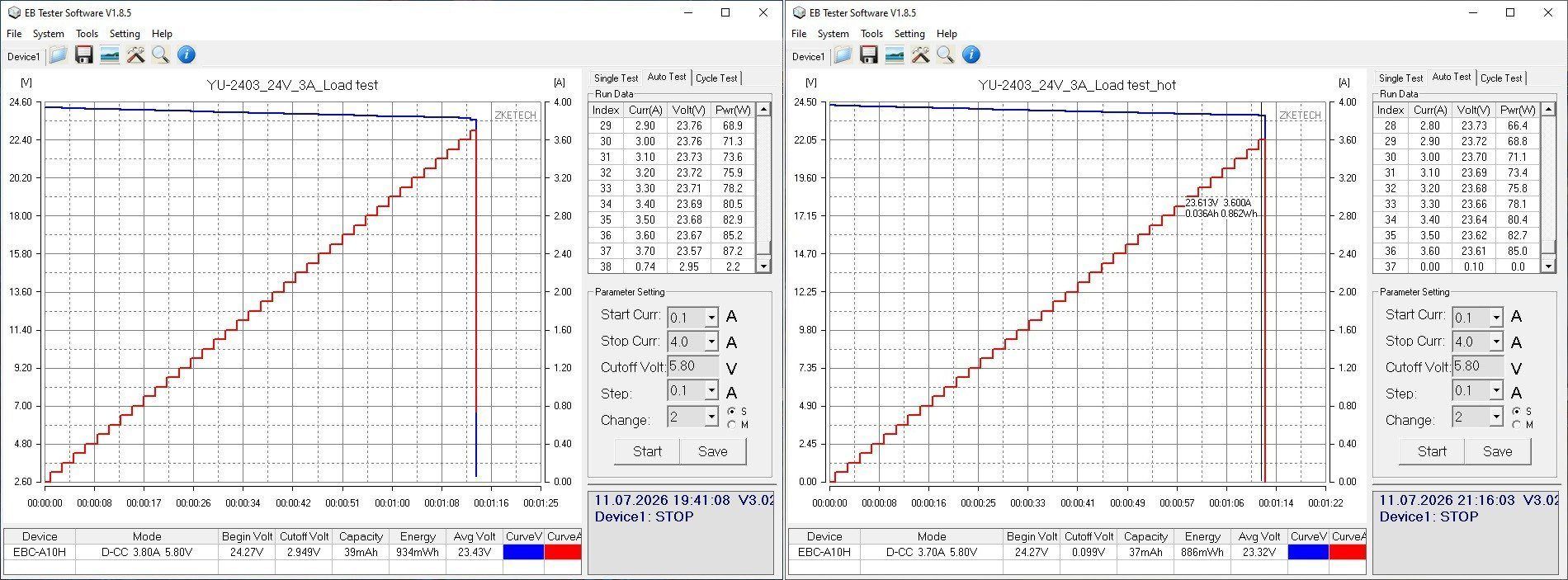
The protection current is set to around 3.7–3.6 A when cold and hot. It could be lowered a little more, but it is acceptable as is.
As expected, ripple is low: even at full power, the main ripple is around 15–20 mV, and no more than 45–50 mV even with the “spikes” included.
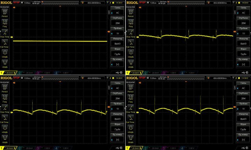
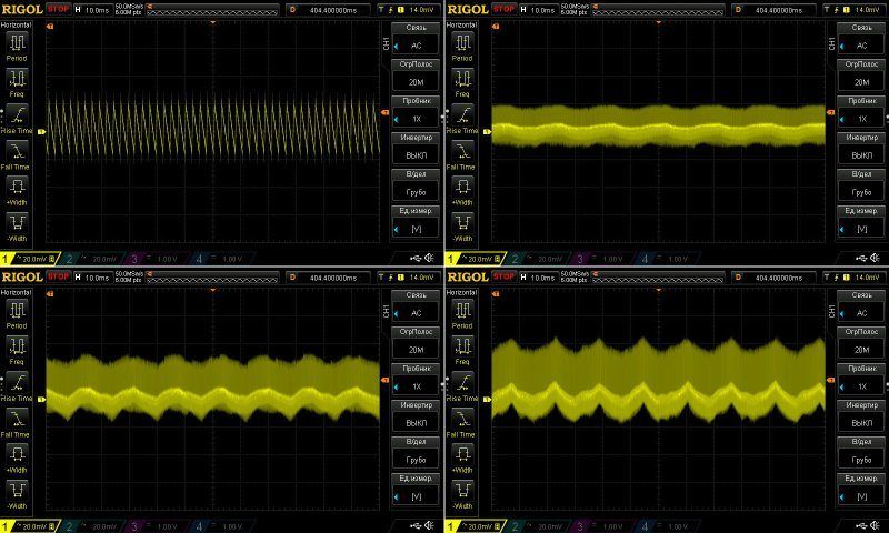
There is a little 100 Hz ripple at low frequencies, but looking at its actual magnitude, it is negligible.
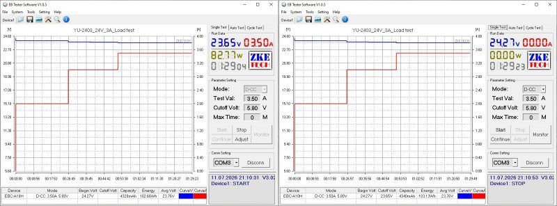
The load test was run at currents of 2, 3 and 3.5 A, i.e. close to the overload shutdown threshold.
There is no change in voltage as the unit warms up—or rather, it is smaller than the electronic load can measure.
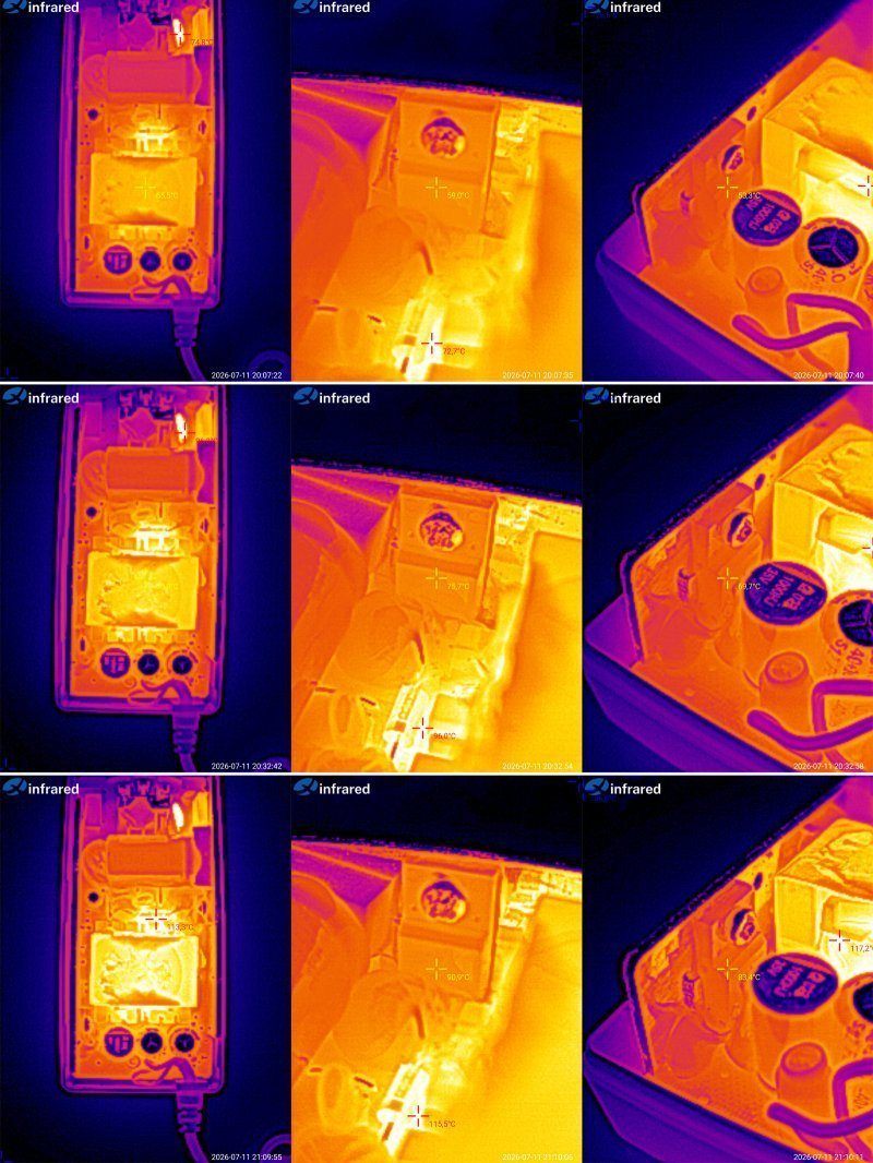
Now for the temperature rise.
At 2 A: transformer 65, transistor 59, rectifier 53 °C
At 3 A: transformer 87 °C, transistor 76, rectifier 70 °C.
At 3.5 A: transformer 109, transistor 91, rectifier 83 °C.
You could say the power supply handles its rated 3 A excellently. In fact, it could handle 3.5 A too, since the only component that started overheating was the transformer—and you may remember that I removed the metal plate that served as its heatsink.
I think this unit would also run at 3.5 A for extended periods in its original form, though I wouldn't recommend it. I'll probably suggest to the manufacturer that they lower the overcurrent protection threshold a little, to around 3.2–3.3 A. That would make overheating this power supply even less likely.
And now we've reached the tests of the 12 V power supplies. There are 10 of them here, but there's a catch: quite a few are essentially the same unit, just with different configurations.
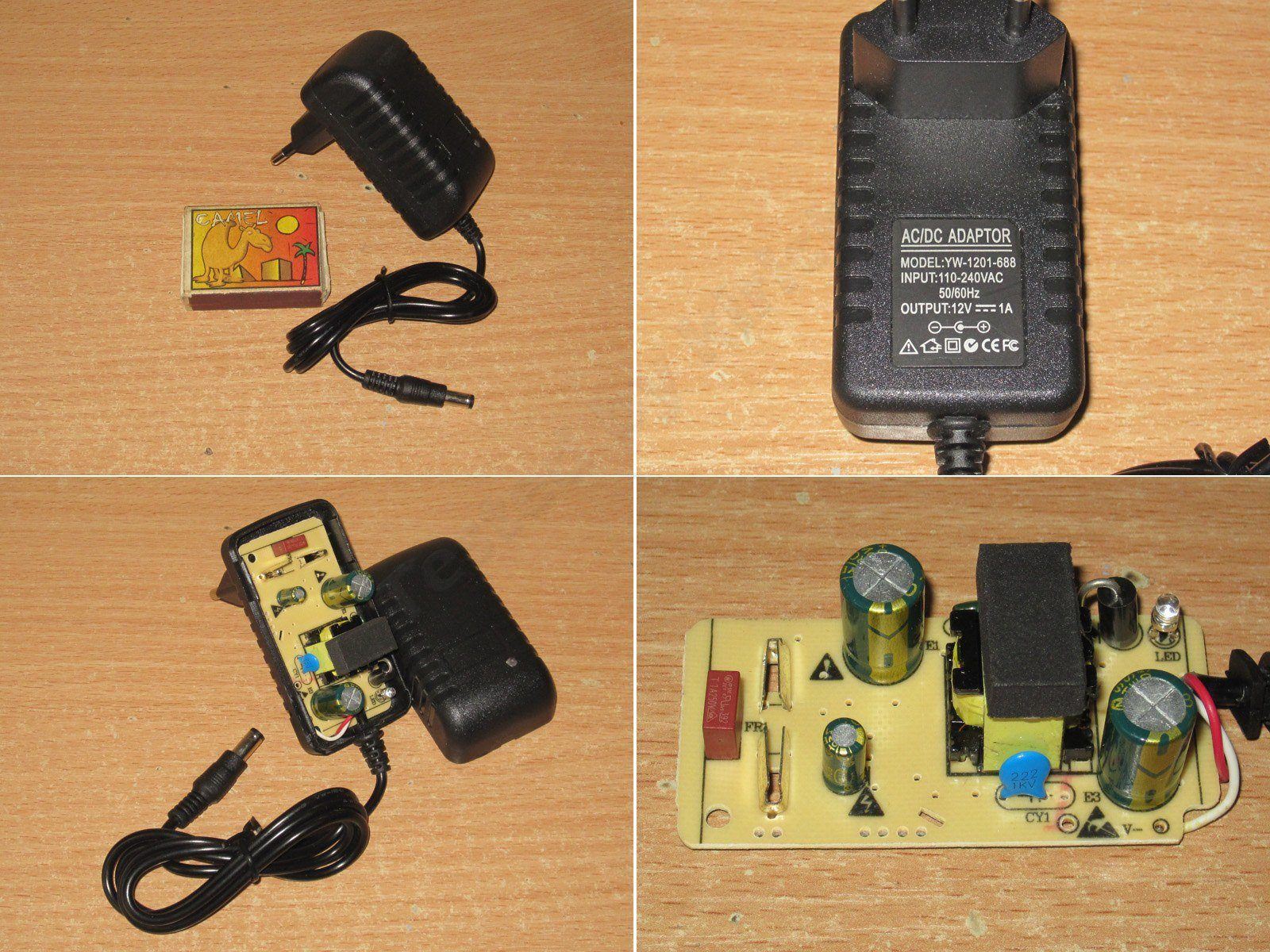
I'll start with the little one: 12 V, 1 A. The case is, of course, an “adapter”; I don't think they make many desktop versions like this.
Right away, we're greeted by some impressive cost-cutting. It looks like they saved on everything. Let's see how it performs. By the way, I don't think I've come across this model—or the next one—in this exact form before, though I've seen very similar, better versions.
One major issue right off the bat: the interwinding capacitor is a standard type, rated for just 1 kV. So this power supply should only be used where people cannot come into contact with any live parts connected to its output. But really, it's easier to install a proper capacitor.
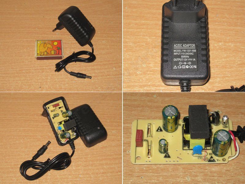
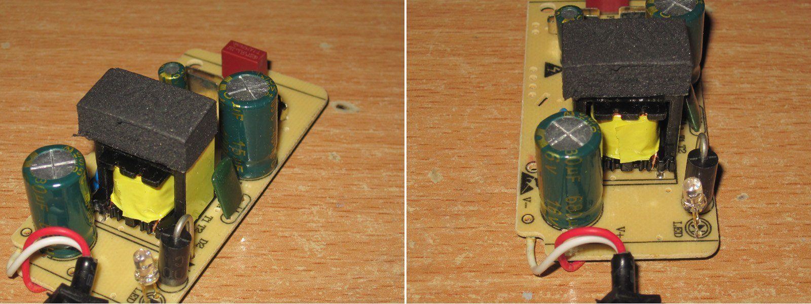
There's a 15 µF capacitor on the input and a 680 µF, 16 V capacitor on the output. The transformer is absolutely tiny.
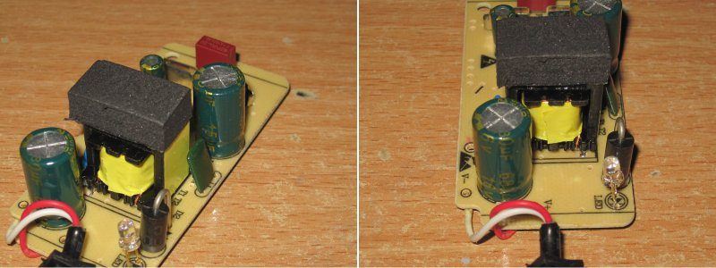
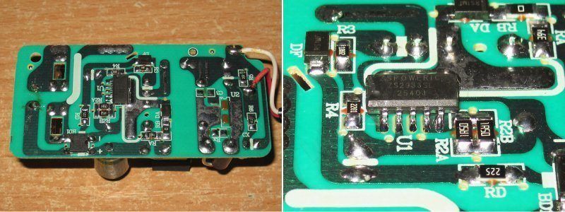
The assembly is generally neat, but I have some concerns about the clearance between the primary and secondary sides: there's a narrow spot.
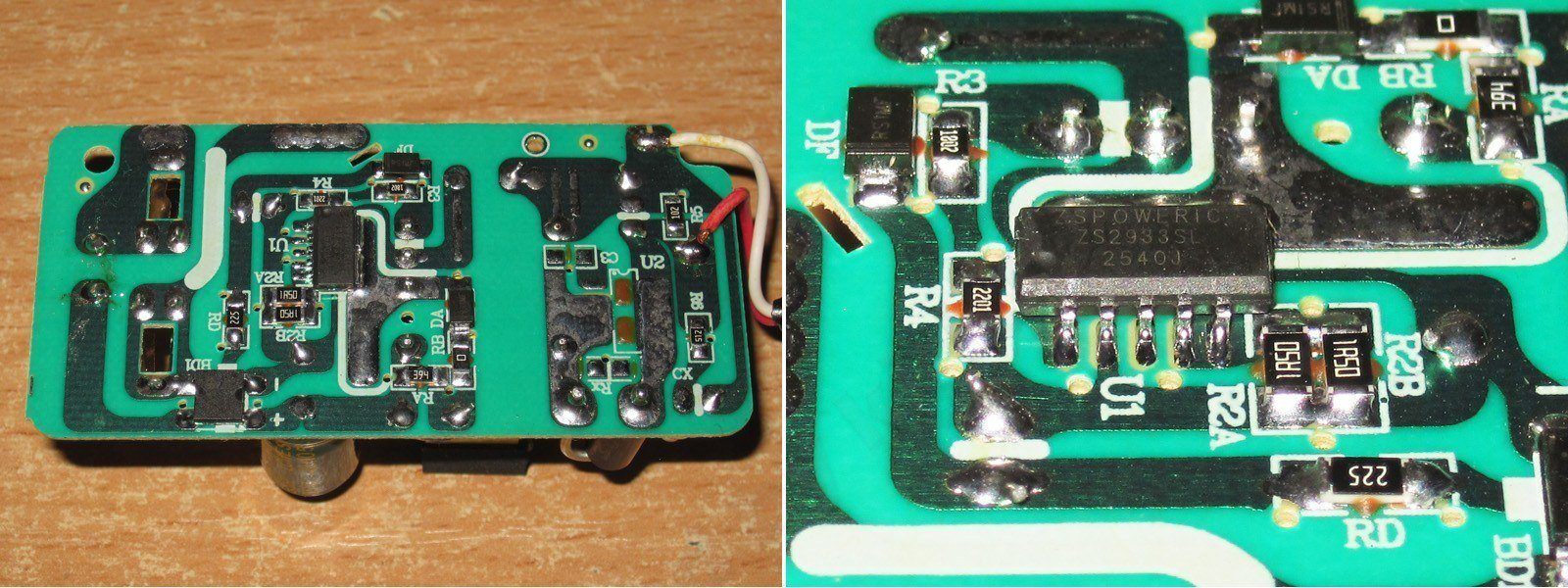
I should note, though, that this uses a dedicated chip with a built-in high-voltage transistor and, very conveniently, an external current-sense resistor.
I remember using a feature of the TOP24x controllers once: you could use a higher-power PWM controller and lower its protection threshold in software, getting slightly better efficiency.
Here, too, you can use a higher-power chip, dial back its protection, and get more reliable operation.
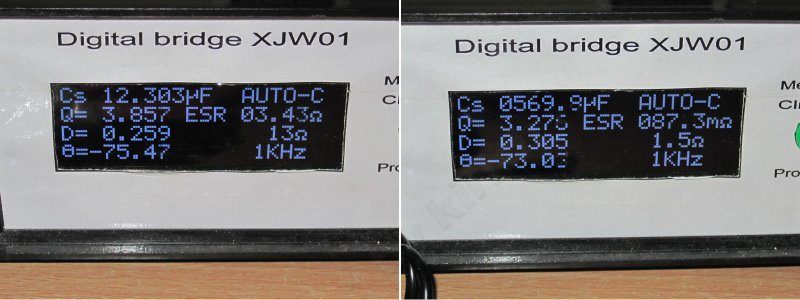
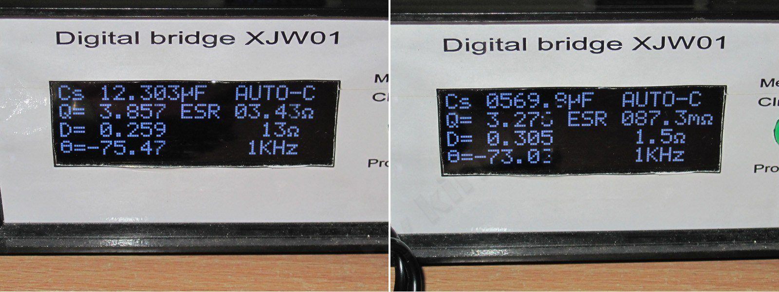
The actual input capacitance is 12 µF, and the output capacitance is 570 µF, but that's fine for a power supply rated at 12 W maximum.
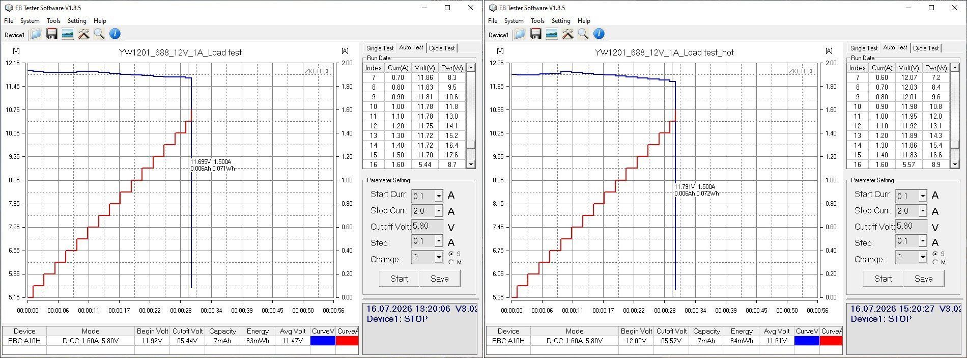
The protection threshold is set to 1.5 A and is almost unaffected by temperature. In my opinion, it should be lowered; around 1.2–1.3 A would be more appropriate.
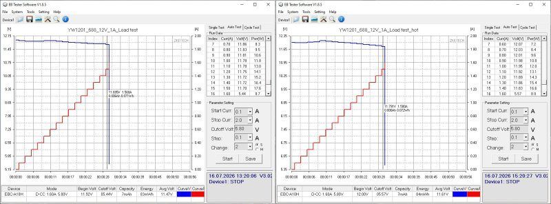
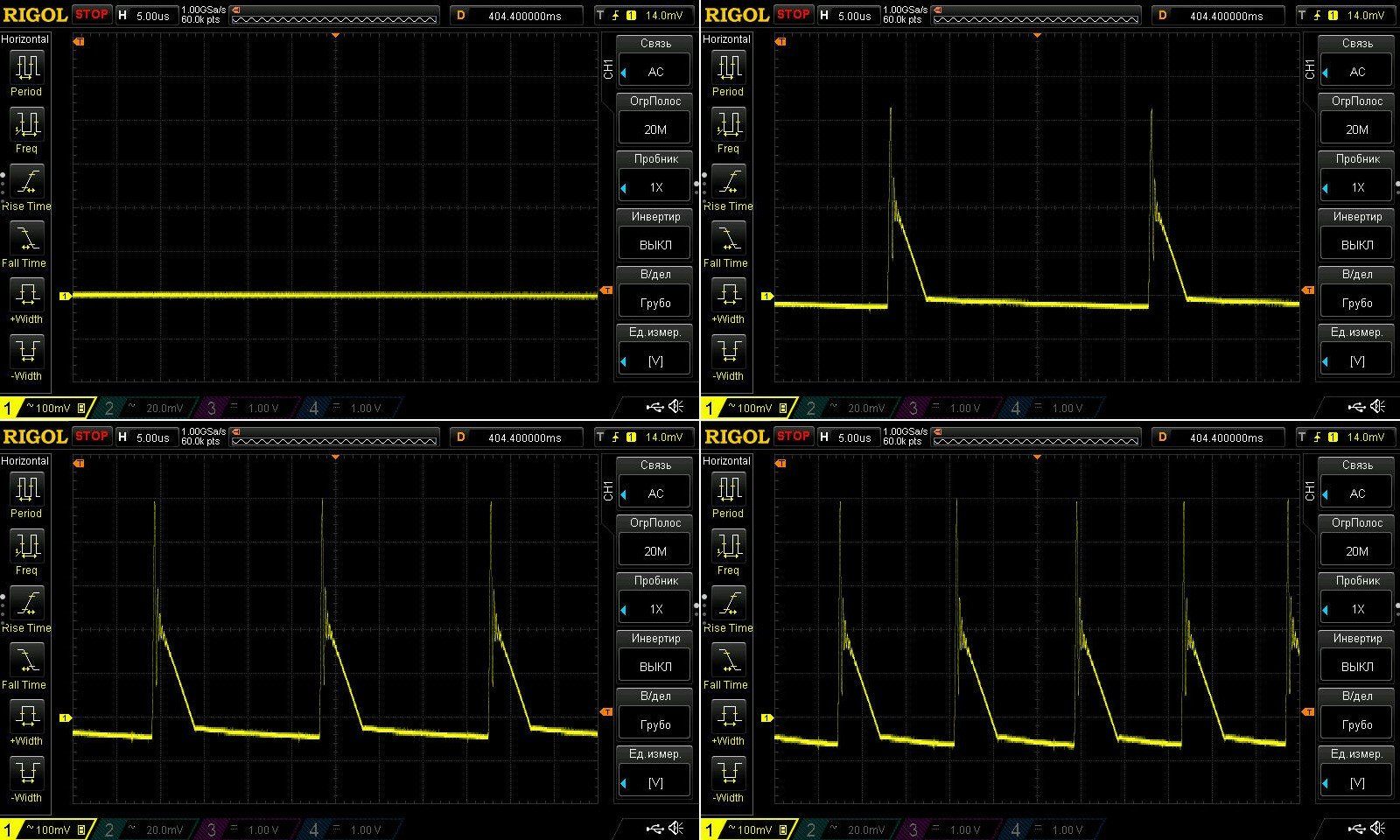
The high-frequency ripple is pretty dismal: the main component is 250–300 mV, and with the “spikes” included, it's 550–600 mV. You can improve things a little by adding a polymer capacitor to the output, without making any other more noticeable changes.
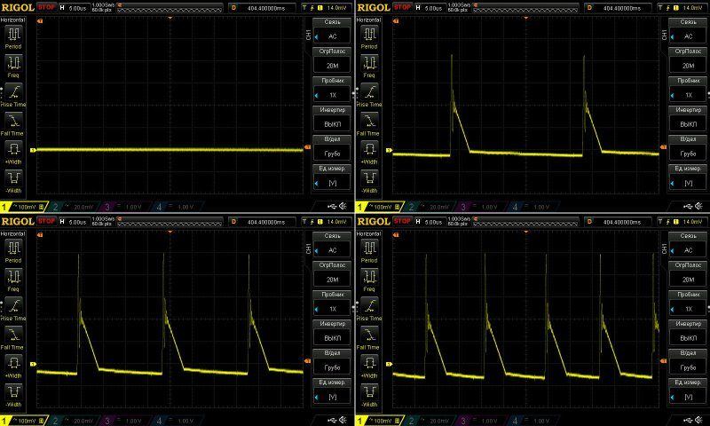
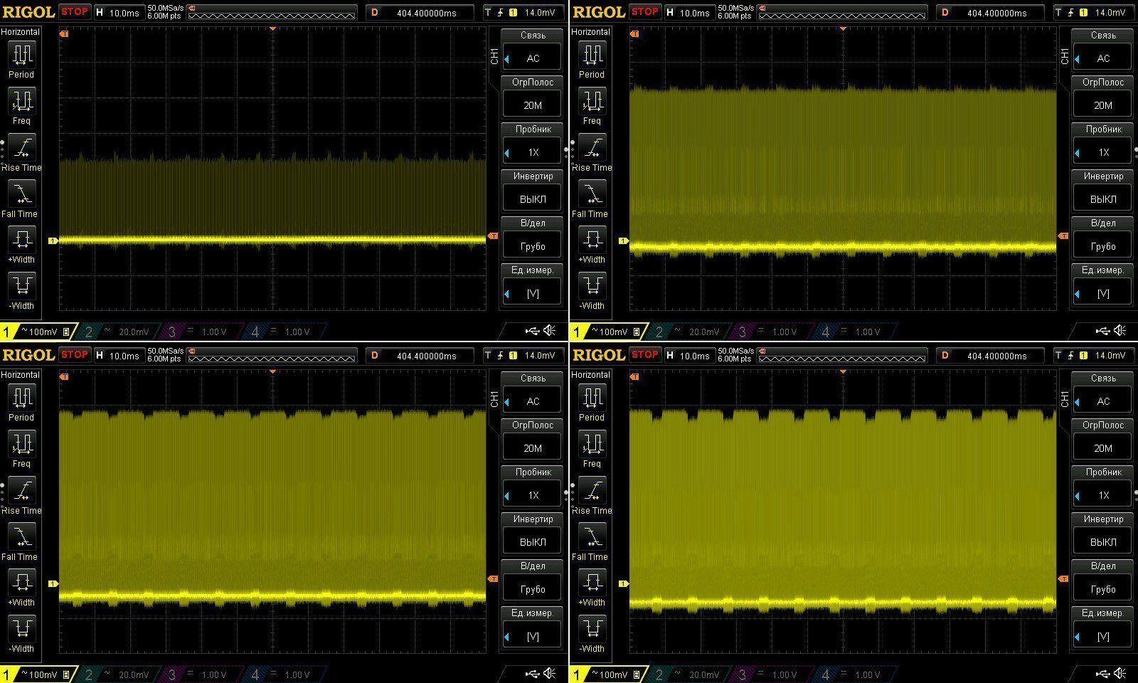
At 100 Hz, everything is more or less as expected: the overall swing is large, but the low-frequency ripple is well within spec.
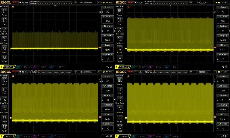
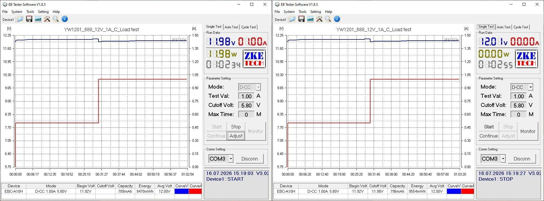
The test was carried out in two stages, at 0.5 and 1 A. Note that the power supply's output voltage changes noticeably as it warms up; this is clear from both the graph and the readings. At the start, the no-load voltage was 11.92 V. After warming up, it rose to 12.01 V. But this is perfectly normal, especially since regulation is done on the primary side.
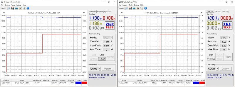
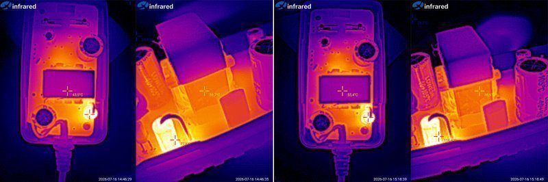
Temperature rise. It was awkward to get to the chip, so check the temperature of the transformer and output diode.
0.5 A — transformer 60, diode 76
1 A — transformer 87 degrees, diode 112.
Well, in principle, the diode does get a bit too hot. You can mitigate that somewhat simply by making its copper area larger. And if you replace the output capacitor with a polymer one, the result will be quite good for a budget unit.
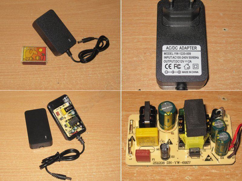
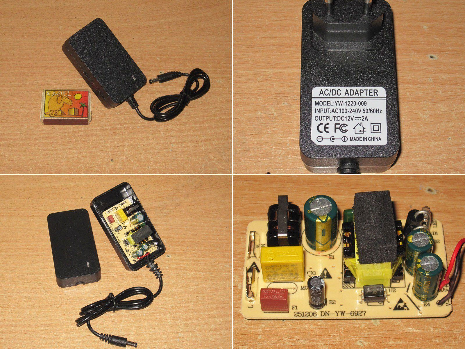
The second 12 V power supply. This one is rated for 2 A; incidentally, its case looks very similar to those used for 24 V, 2 A power supplies.
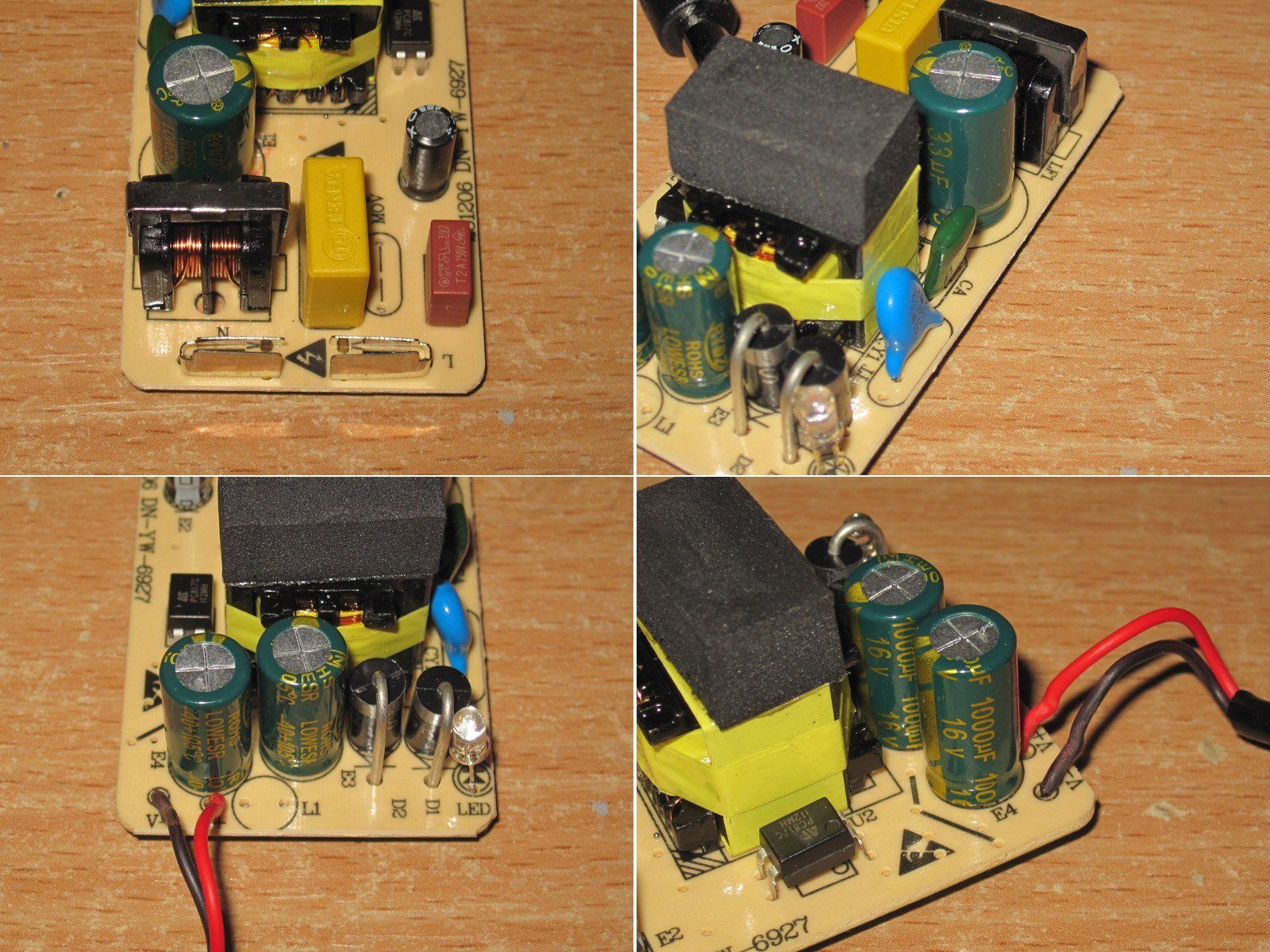
The transformer is also not very large, but the internals are clearly more substantial. It has an input filter, two output capacitors, and an optocoupler.
Overall, everything is much better here. They even fitted a Y capacitor rather than an ordinary one, as in the 1 A version.
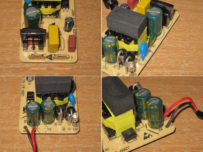
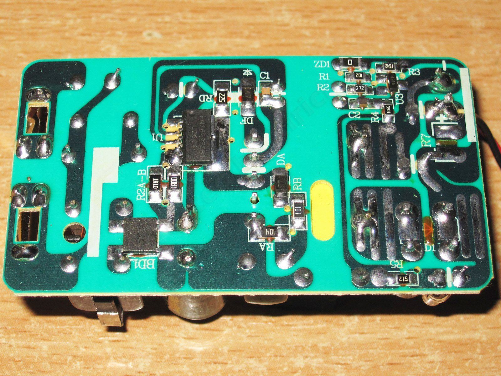
I have no concerns about electrical safety either. This power supply is based on a chip similar to the one in the previous model, so it most likely has overtemperature protection as well.
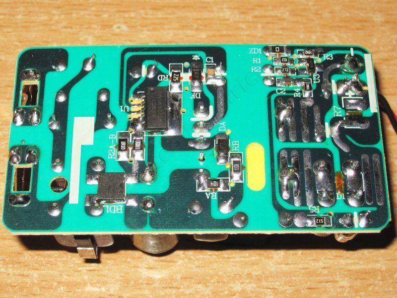
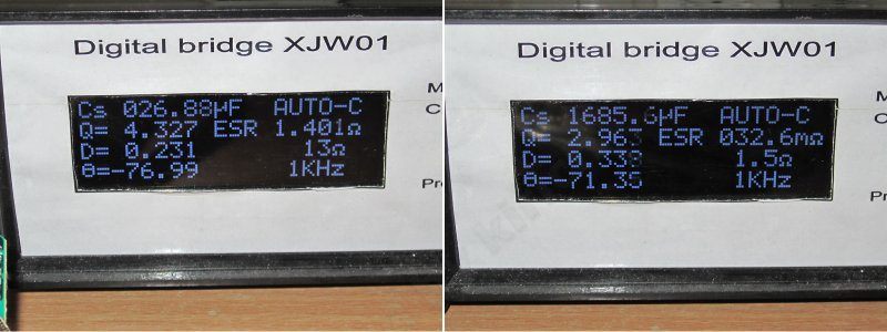
The input capacitor is 27 µF, and the output capacitors total 1700 µF. No complaints.
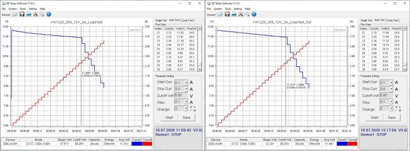
The protection current is set to about 2.3 A. The shutdown isn't abrupt, but fairly gradual; essentially, the power supply just lowers its output voltage. This isn't good or bad—it's simply one type of protection.
Ripple is better here: at maximum current, we get 170/230 mV. That's perfectly normal for a budget power supply, though of course lower is always better. One possible fix, again, is to replace one of the capacitors with a polymer one. I could have run an experiment, but I already have a pretty good idea of the result.
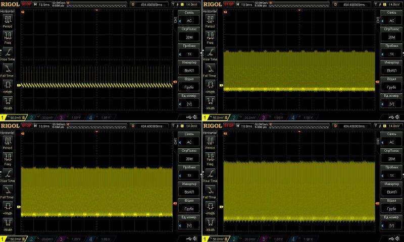
There is practically no ripple at 100 Hz.
Testing was done at 1 A and 2 A, and I let it run for quite a while.
I have no complaints about voltage regulation, and the effect of heating is almost nonexistent—just about 20 mV.
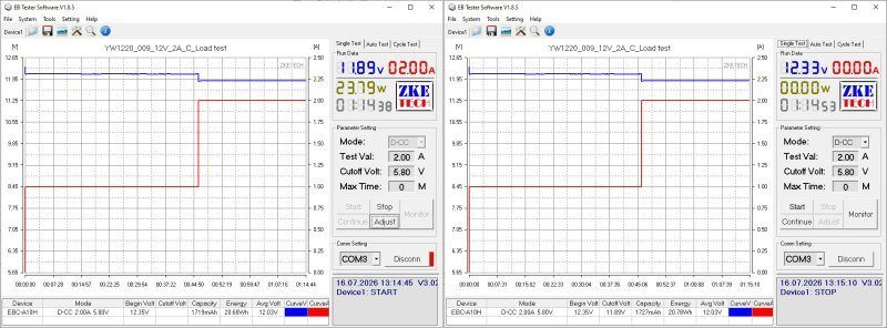
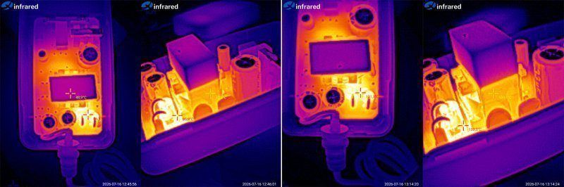
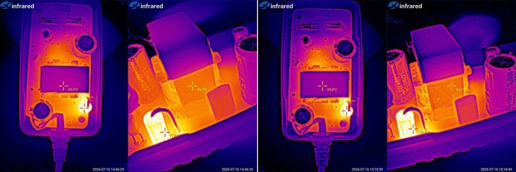
Let's check the temperatures.
1 A — transformer 73, diodes 86 degrees.
2 A — transformer 110, diodes 131 degrees.
Subjectively, the actual continuous current for this power supply is around 1.5 A. At 2 A, it clearly overheats, so either it needs modification or it should be sold as an honest 1.5 A unit.
At last, I've reached the models I've already had through my hands. I don't remember which iteration this is, but some work has clearly been done on this one.
The result is a number of standardized models that caught my eye in the first place, but ultimately needed some time and hands-on work from me.
A 12 V, 3 A model in the “adapter” form factor. This is exactly how it first came to me.
There's an input filter, components with plenty of headroom, and a large transformer.
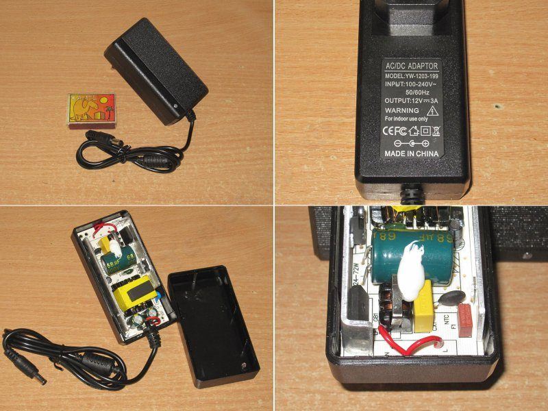
It looks fairly basic on the outside, but I liked that it worked quite well.
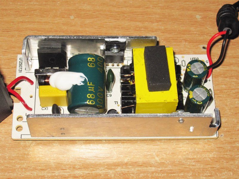
The transistor marking is almost unreadable. I should look for earlier versions; maybe it's legible on those. The output has a pair of 1000 µF capacitors.
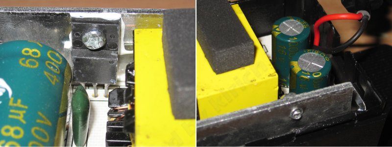
For safety, I'd give it more like 4 points. There are some weak spots, but overall it's reasonably tidy. And, incidentally, the PWM controller's supply resistor is made up of two resistors here as well, which is the right way to do it.
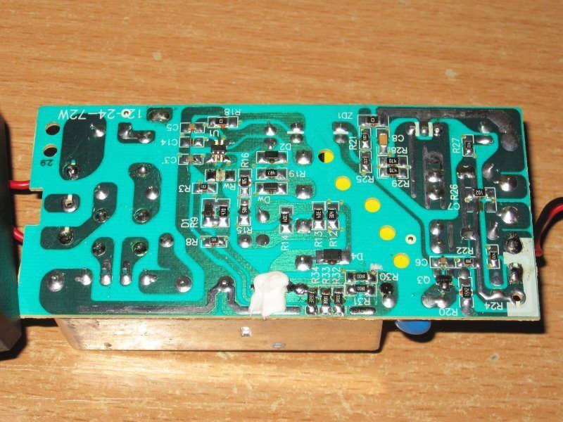
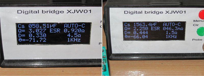
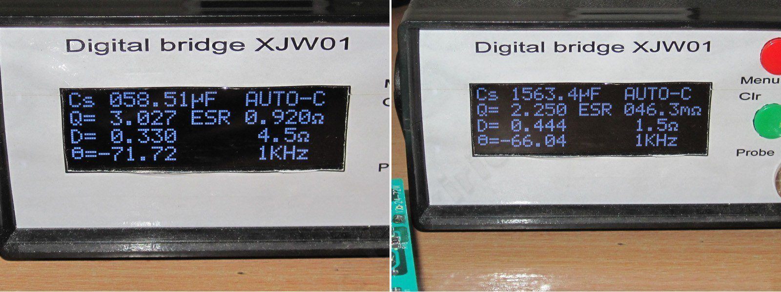
The input capacitance is 58 µF, and the output capacitance is 1560 µF in reality. That's quite reasonable for a 36 W model, and it should work at both 230 V and 115 V.
The protection current here is set in line with our recommendations and the positioning of the specific models.
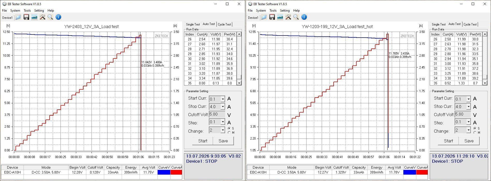
Here, the protection current is set to 3.4 A, i.e. basic 3 A plus a little headroom.
High-frequency ripple at maximum current has a peak-to-peak amplitude of about 130–140 mV, which is roughly 1% of the output voltage and is normal.
A reminder: ripple was measured directly at the board output in every case; it will be lower after the cable.
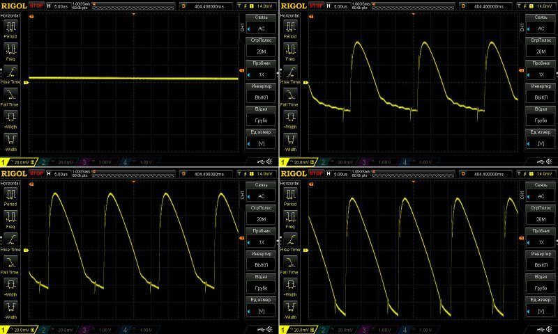
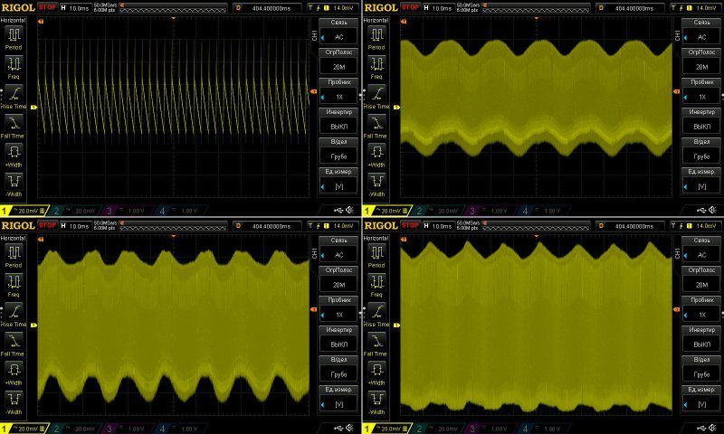
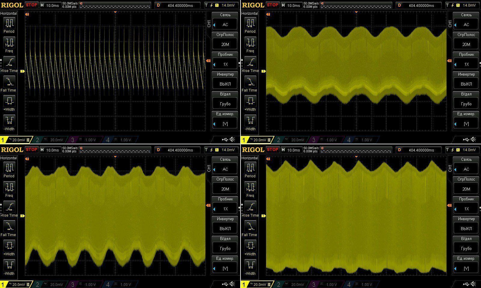
There is some ripple at 100 Hz, but I’d say it’s acceptable.
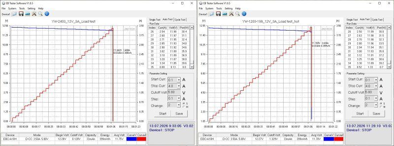
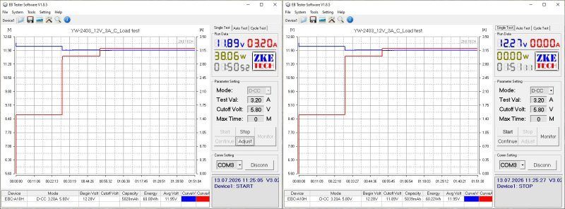
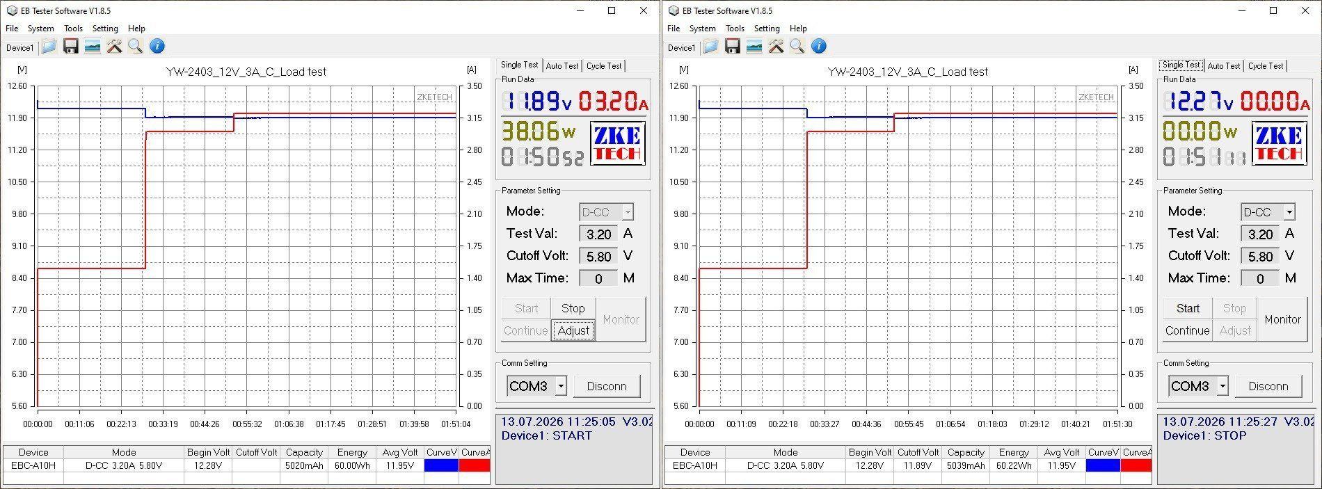
The test was carried out in three stages, at currents of 1.5, 3, and 3.2 A, with the 3.2 A stage being the longest.
The voltage does depend on the load, of course, but that’s voltage drop across the cable. The effect of warming up is practically nonexistent, so I think we can safely ignore those 10 mV :)
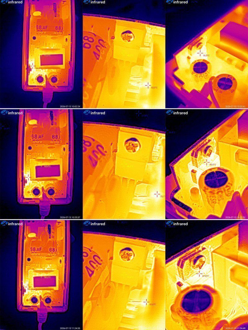
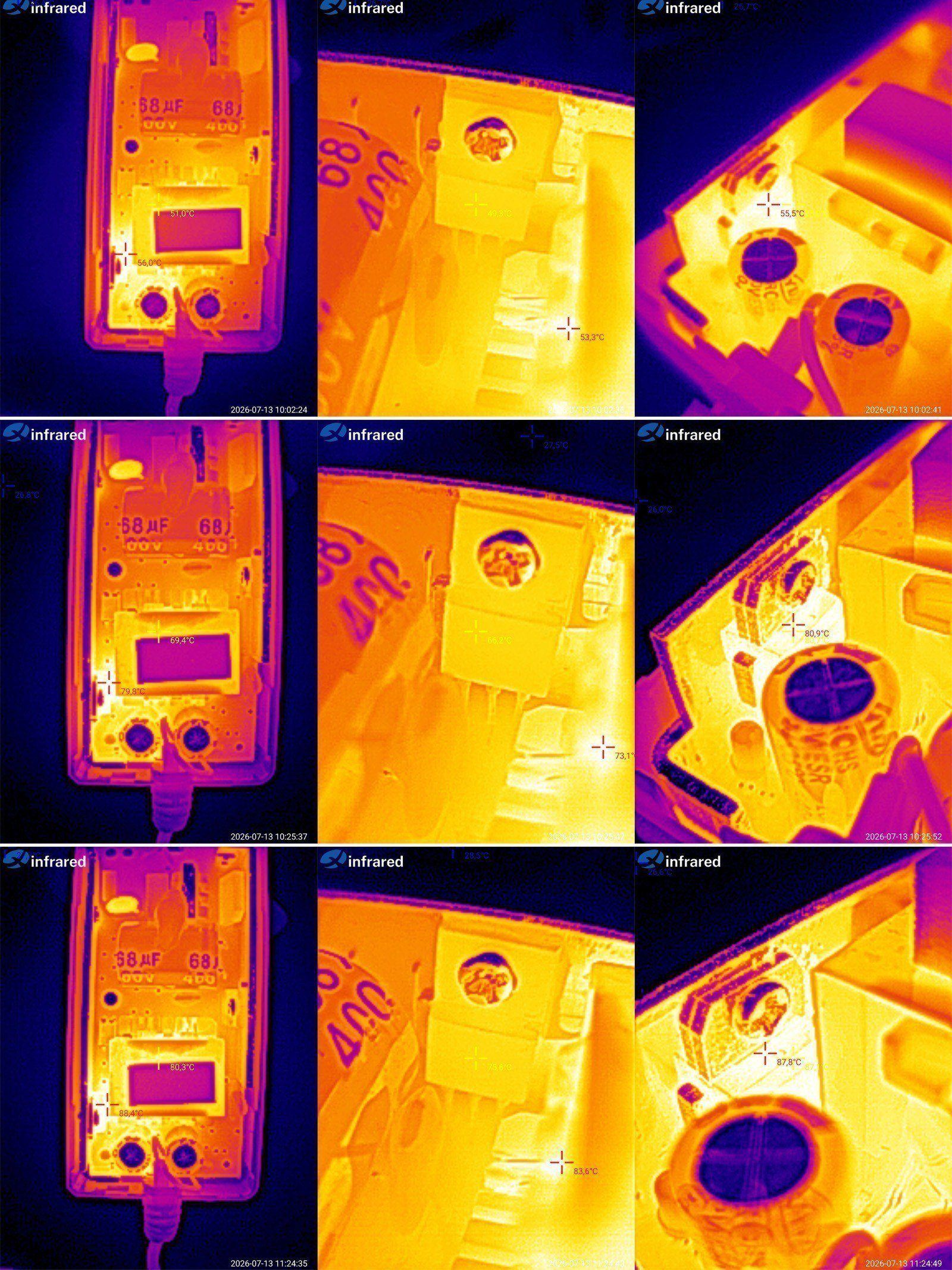
And most importantly, the temperature.
At 1.5 A: transformer 51, transistor 49, and output diode assembly 55 degrees.
At 3 A: transformer 69, transistor 66, diode assembly 81 degrees.
At 3.2 A: transformer 80, transistor 77, diode assembly 88 degrees.
As you can see, nothing is overheating. All the main components are operating with a noticeable margin, so we’ve achieved our goal for now.
The next model has the same specs, 12 V, 3 A, but in a desktop form factor. This was Vitaly’s idea; we work together to push the Chinese manufacturers. Since it doesn’t really make much difference in this case, I had no objections.
This unit doesn’t even have a label; they just wrote on it with a marker and sent it for approval.
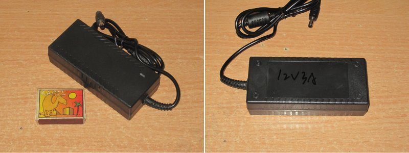
As you can see, it’s essentially exactly the same power supply as the previous one, but in a different enclosure. This model is perfectly viable as a product: not everyone wants a power supply in adapter form, just as not everyone wants a desktop version.
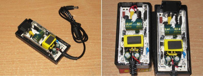
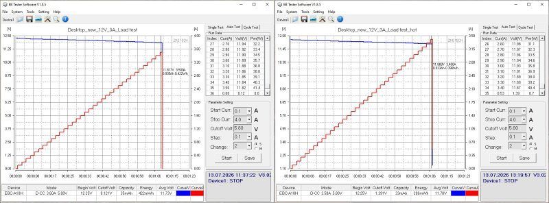
There’s no point inspecting anything or measuring the capacitors, so let’s go straight to testing the protection current.
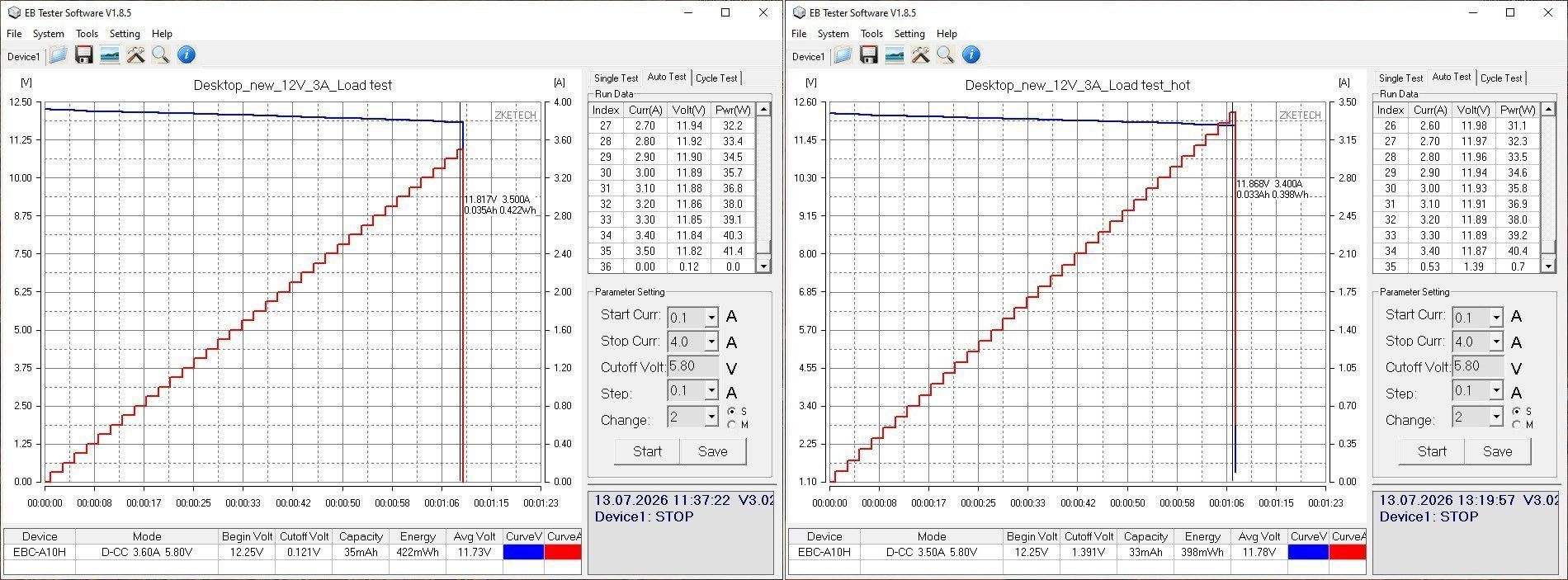
We get the same 3.4–3.5 A, just as we wanted.
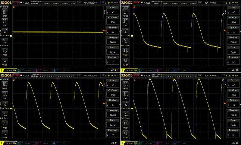
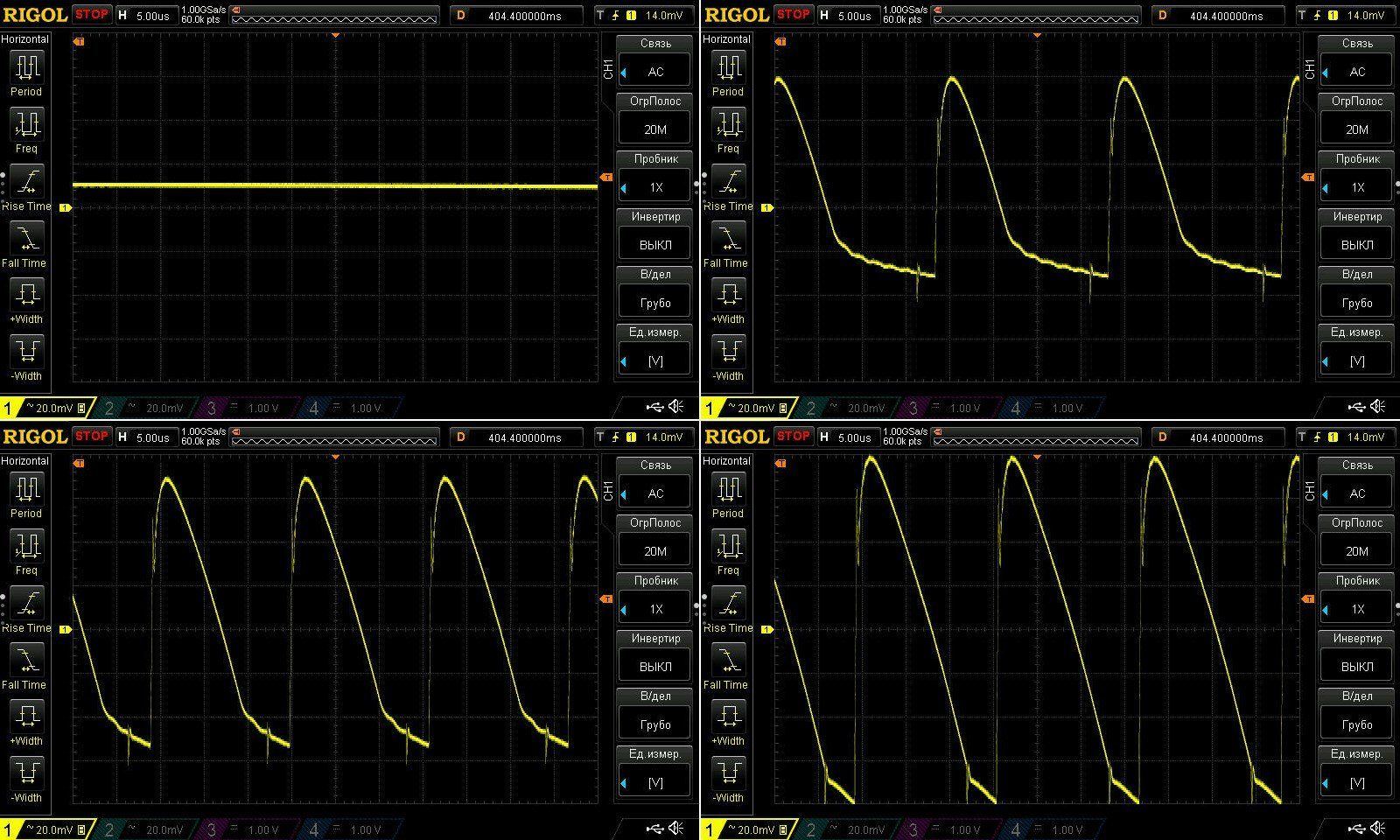
The ripple is about the same, which was also expected.
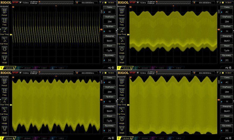
The warm-up test was run in almost the same conditions and at the same currents: 1.5, 3, and 3.5 A.
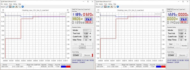
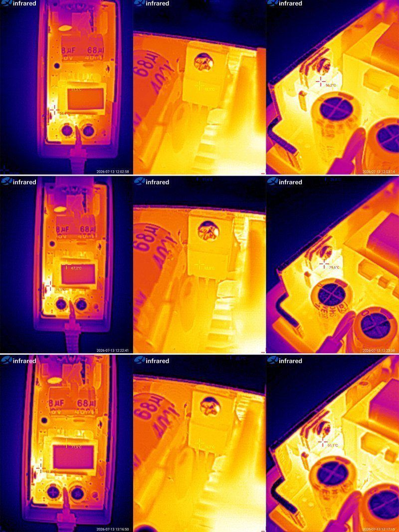
Temperature measurements for the main components.
At 1.5 A: transformer 52 degrees, transistor 48, diode assembly 56 degrees.
At 3 A: transformer 67 degrees, transistor 64, diode assembly 80
At 3.2 A: transformer 78, transistor 76, and diode assembly 91.
In the end, the temperatures are more or less the same: some components are a little hotter, others a little cooler. In any case, everything is within the normal range.
The next model is based on the same platform, if you can call it that, but is rated for 12 V, 4 A, or 48 W.
Adapter form factor, but with a few improvements.
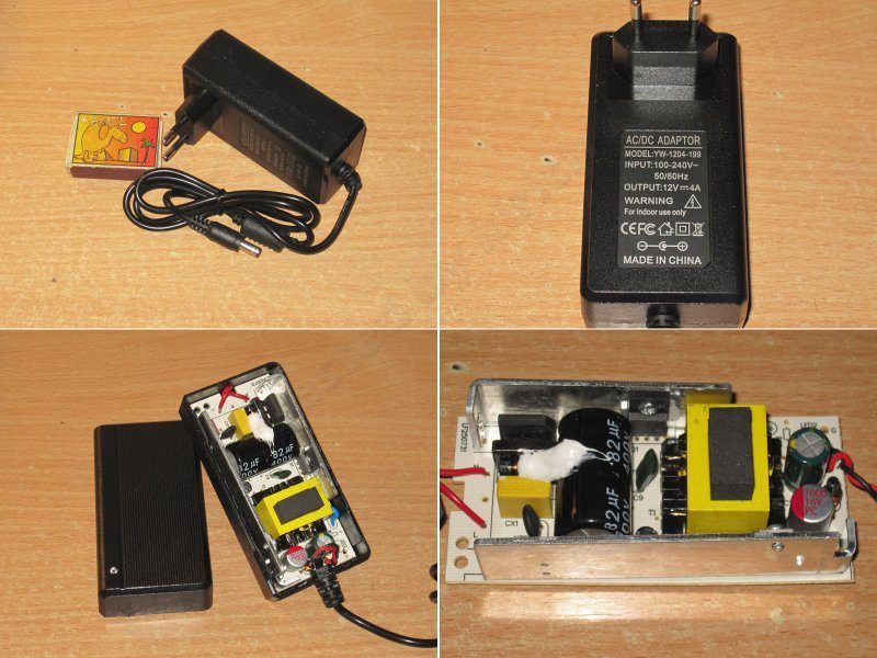
The input filter was retained. I can’t remember about the transistor now, but I think they asked for a more powerful one, though I could be wrong. The input capacitor, however, has a higher capacitance.
One of the output capacitors has also been replaced with a polymer capacitor, and the output inductor is rated for a higher current. The one fitted originally got noticeably warm at 4 A.
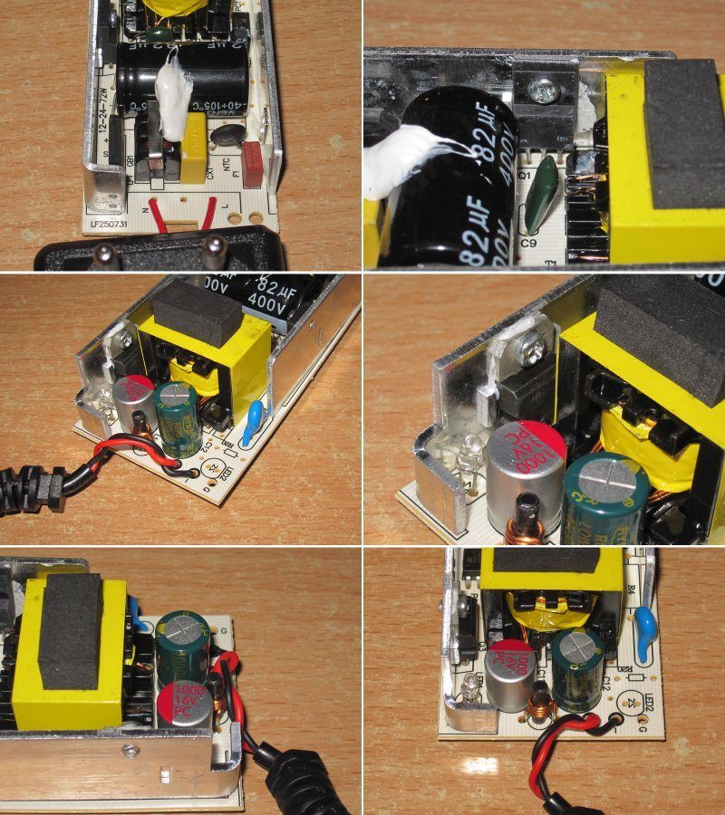
It’s the same board, but the shunt values have been adjusted for the different output current. The factory team handled the adjustments and sent videos of the tests along the way.
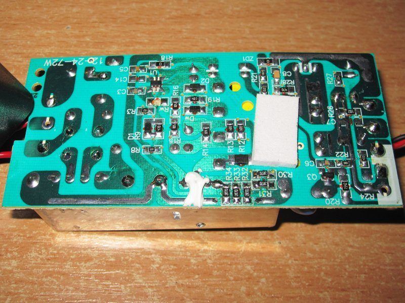
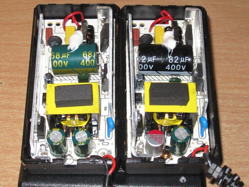
The 3 A model is on the left, the 4 A model on the right. You can see that the basic design is the same; only a few components have been changed.
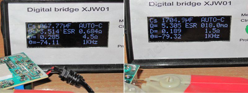
The input capacitor measures 67 µF, and the output capacitors total 1800 µF. Here, too, we got what we wanted.
The protection current came out to about 4.5 A when cold and 4.3 A when hot, i.e. close to the stated maximum.
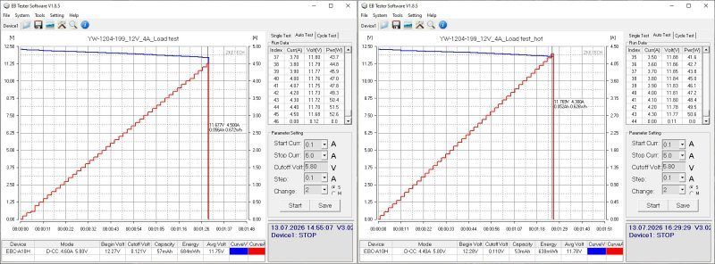
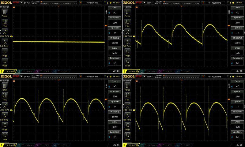
As I mentioned, the output stage was modified, which gave us noticeably less ripple at the output. Even at maximum current, we get 35 mV of main ripple and 60 mV including the "spikes"—pretty good, in my opinion.
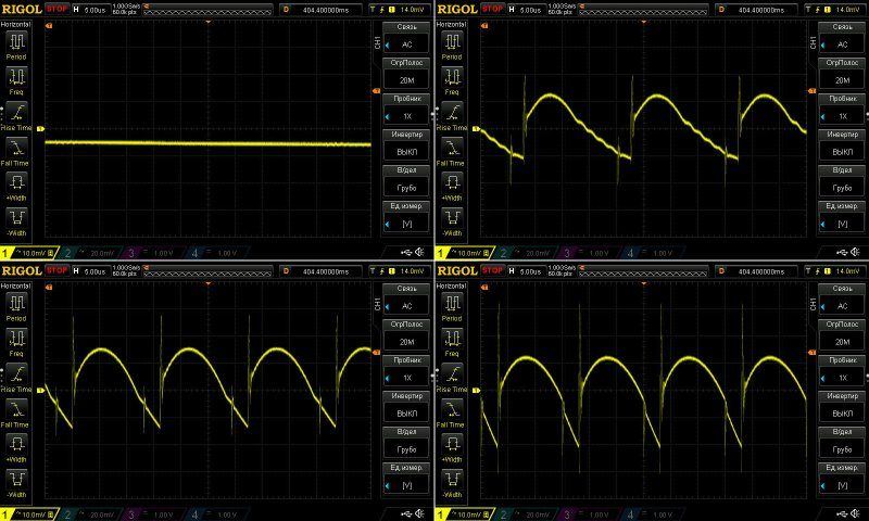
At 100 Hz, the waveform looks pretty scary, but it’s not actually that bad. The high-frequency ripple is simply small, so the 100 Hz ripple stands out more against it, especially with the oscilloscope set to 10 mV per division.
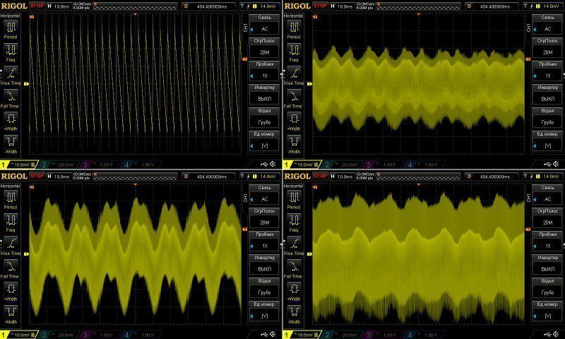
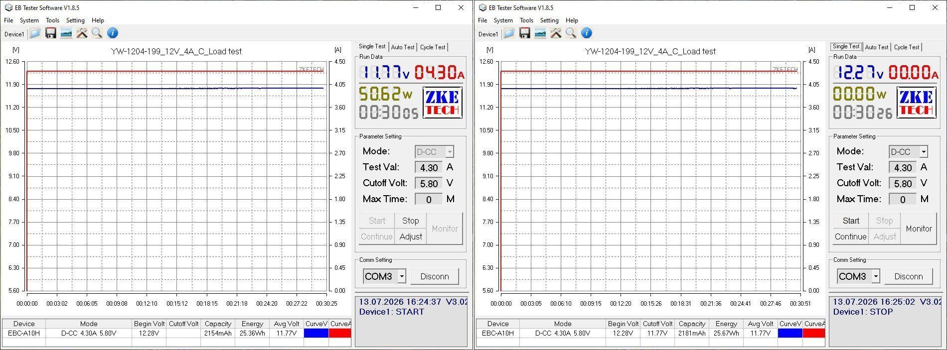
This test ran at 2, 4, and 4.3 A, but unfortunately it was briefly interrupted during the final stage, which caused the load to switch off. I resumed the test right away, but sadly there’s no continuous graph.
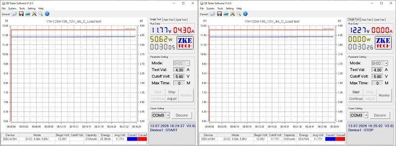
Now for the temperatures.
2 A — transformer 55 degrees, transistor 54, diode assembly 68
4 A — transformer 82 degrees, transistor 82, diode assembly 97 degrees.
4.3 A — transformer 90, transistor 90, and diode assembly 103 degrees.
All temperatures are within the normal range, but yes, there isn’t much headroom for higher ambient temperatures. I think it should handle somewhere around 15–20 degrees above normal room temperature.
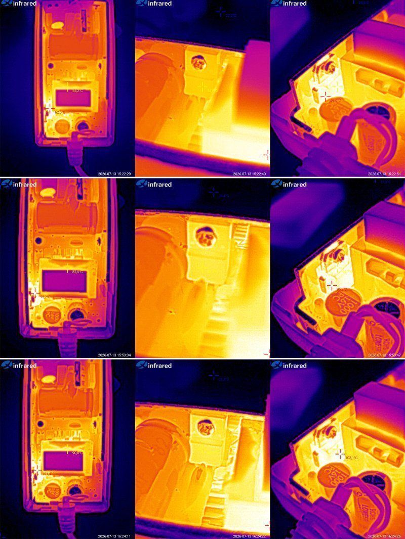
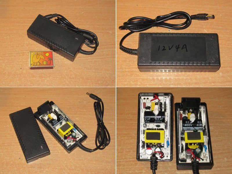
This is the same power supply, but in a desktop enclosure. Yes, the only difference is the type of enclosure.
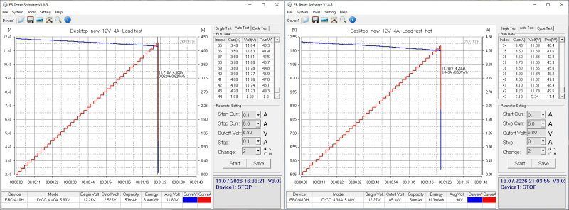
The protection current ended up a little lower here. On the other hand, nobody expected this parameter to be precise; the main thing was for it to be slightly higher than the rated output current.
As I’ve already explained, too much current is bad, because then nothing stops the user from loading the power supply "to the max" and ending up with a lump of charcoal.
The ripple is much the same, since the boards are identical.
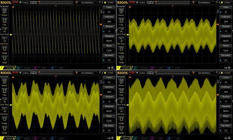
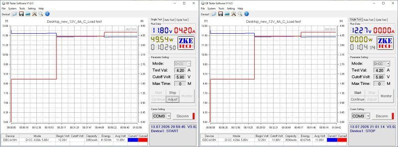
Since the protection current is set a little more "gently" here, the test ran at 2, 4, and 4.2 A.
The power supply holds its voltage very well. The cable does drop almost 0.5 V under full load, but the voltage still stays within tolerance.
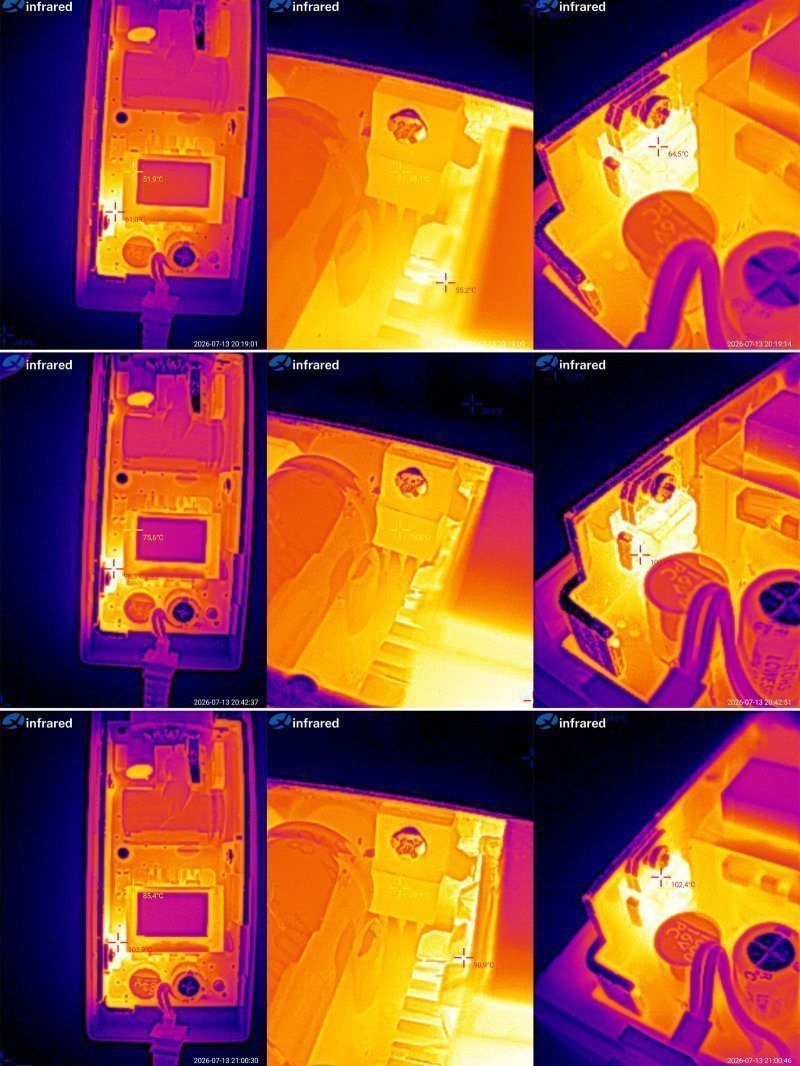
Temperatures.
2 A — transformer 52 degrees, transistor 49, diode assembly 65
4 A — transformer 76 degrees, transistor 75, and diode assembly 100
4.2 A — transformer 85 degrees, transistor 79, diode assembly 102.
As expected, the difference from the previous unit isn’t very large and is mostly due to warm-up, so the final readings are more representative. In any case, there’s still some headroom for higher ambient temperatures, even at maximum load, which is certainly good.
The even more powerful model, 12 V 5 A, is also simply labeled with a marker, since it’s a pre-production sample.
And as you can see, it’s based on the same board, but with a few changes.
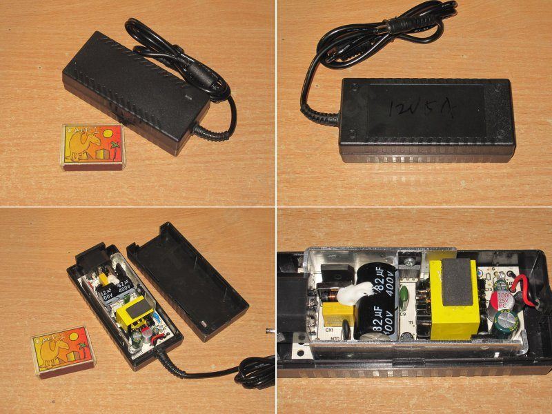
No changes on the input side; on the output side there are three capacitors instead of two. This was the factory engineers’ initiative. The PCB routing has also been changed slightly, again to improve things. The latter point is somewhat debatable, but I’m basically fine with it.
The inductor has higher inductance and current ratings; let’s see how it performs.
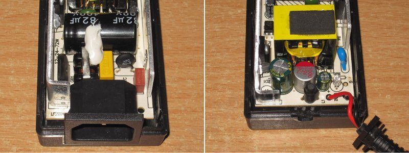
I couldn’t make out the transistor marking, but I did see that, at our request, they installed a synchronous rectifier on the output. I’ve actually already tried all this, i.e. The process goes like this: I get a sample, replace some components myself, show in photos what needs to be replaced with what, and send it to the factory. They make the changes, test it, set the protection current to our requirements, and send back samples. If everything looks good, it goes into production.
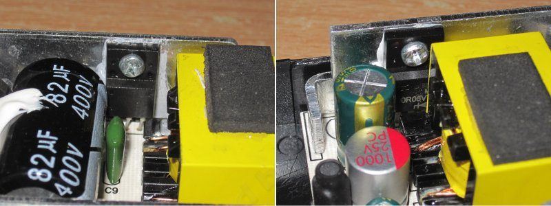
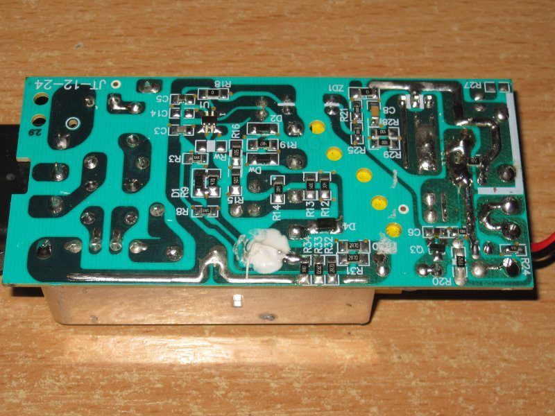
As I said, the board changes are cosmetic, but I should note that the output traces have been reinforced and the board layout has also been revised.
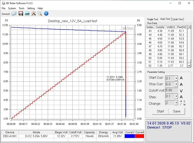
The protection current is right on the limit here: 5.1 A against the specified 5 A. We could try raising it to 5.2 A, but we can also leave it as is.
The high-frequency ripple is mostly around 15 mV, with a total peak-to-peak amplitude of 20 mV including the “spikes”—excellent.
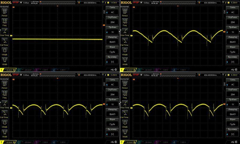
At 100 Hz, everything looks good except when running at the maximum current of 5 A. I should also note the relatively large ripple amplitude with no load, a characteristic of the “green” mode.
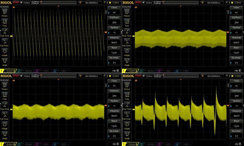
The large low-frequency ripple at maximum current is also a characteristic of how the protection works.
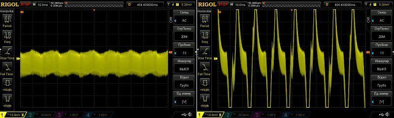
Here are the results at 4.9 A and 5.1 A. You can see that things get ugly at 5.1 A; after that, the protection shuts the power supply off.
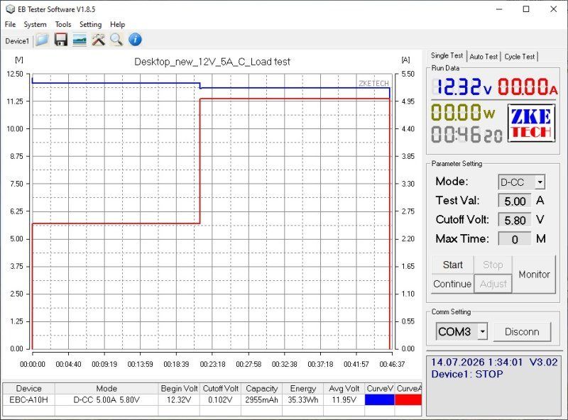
This test was run at 2.5 A and 5 A. I think the power supply itself stopped it after warming up, though honestly, I may have forgotten.
In any case, the total test time was 45 minutes, which is enough to assess it.
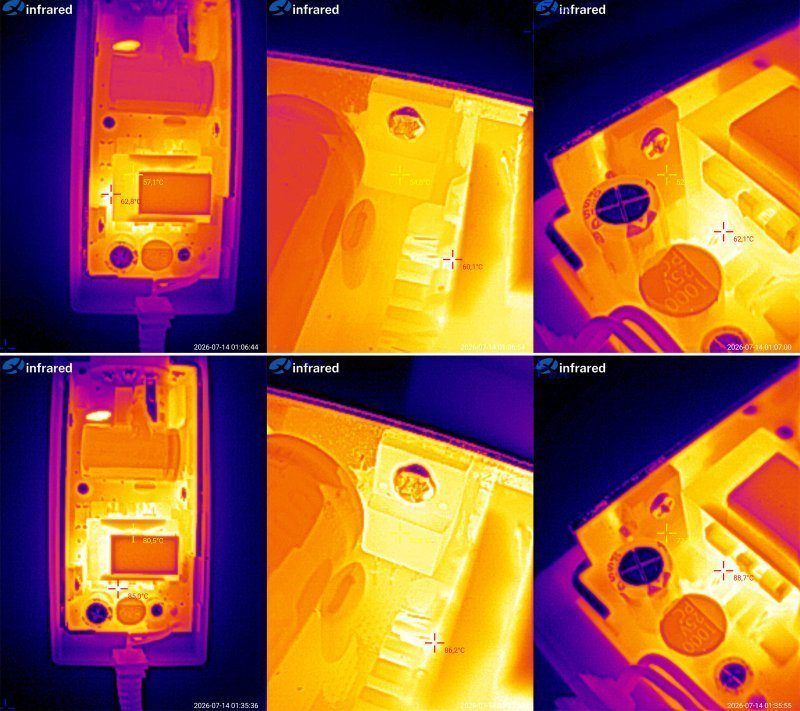
Temperatures
2.5 A: transformer 57 degrees, transistor 55, rectifier 52.
5 A: transformer 80 degrees, transistor around 80 (hard to see), rectifier 72 degrees.
The results are excellent. You may be wondering how a 5 A power supply can have lower component temperatures than the same 4 A model.
The thing is, it isn't quite the same. We replaced the diode assembly with a synchronous rectifier, improving efficiency and reducing the heat generated inside the case. Since the case has a fixed ability to transfer heat to the surroundings, we ended up with a more powerful power supply on the same board and in the same case, without much extra cost.
Technically, we could probably have pushed this board to 6 A, but we decided not to. It can realistically handle 5.5 A—I tested it—but we dialed it back a little by adjusting the protection parameters.
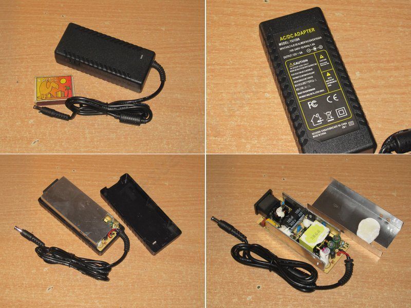
The next model is 12 V, 6 A. It looks quite similar to the previous ones, but is based on a different board.
I think it was originally a 5 A power supply, and there was an almost identical 6 A version. But after running the numbers, we found it was easier to take the 5 A model and upgrade it to 6 A.
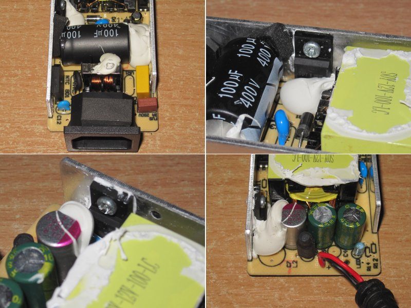
The input side also has a filter, a decent capacitor, a reasonably good transformer, and a proper Y capacitor.
On the output side, we suggested replacing one of the three capacitors with a polymer capacitor, swapping the diode assembly for a synchronous rectifier, and installing an inductor rated for higher current.
I have no major concerns about electrical safety; the board is similar to the previous ones. There are signs of hand soldering, but this is also a pre-production sample, so that's perfectly normal.
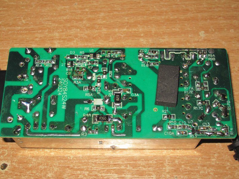
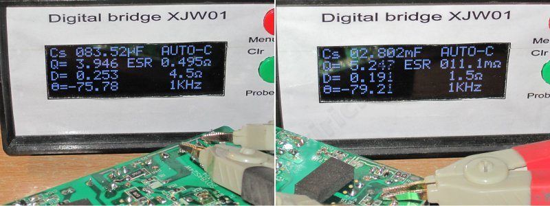
The input capacitor is 83 µF, and the output capacitors total 2800 µF. I have no complaints here at all; that's quite enough for the specified 72 W.
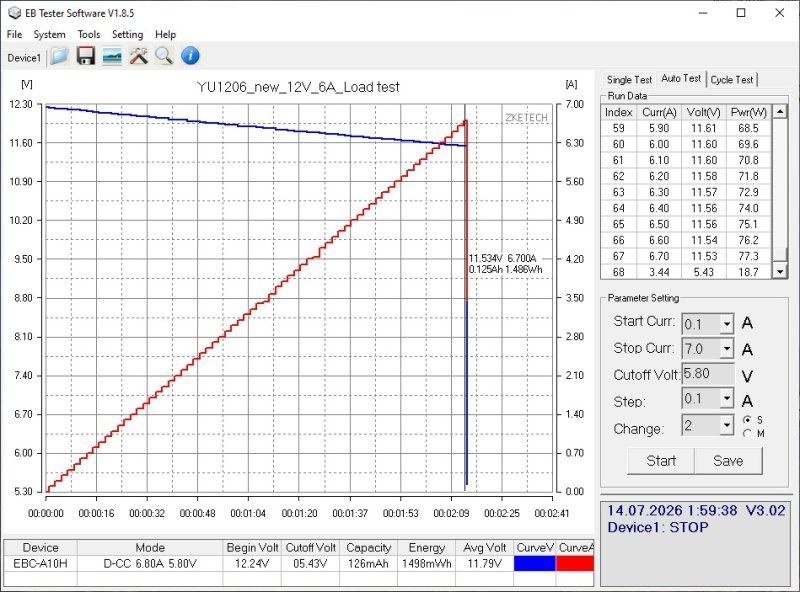
The protection current is set to 6.7 A. I think it may be worth lowering it further, to around 6.3–6.4 A.
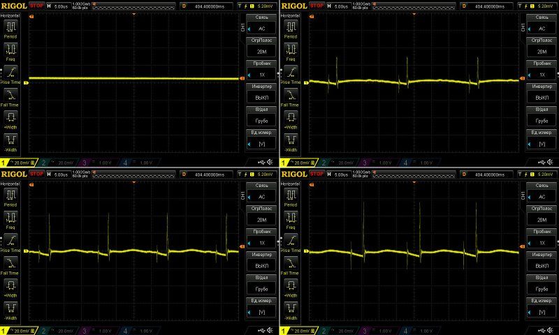
The high-frequency ripple looks a little odd. I think we should double-check the routing, because the main ripple is very small—less than 10 mV—but there are “spikes” with an amplitude of up to 60 mV.
Of course, in practice, all of this can be ignored, but you always want to make things as good as possible. That said, it would mean picking up the soldering iron and experimenting. So most likely, we'll leave it as is for now.
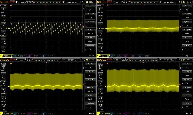
At 100 Hz, everything looks fine; I have no complaints.
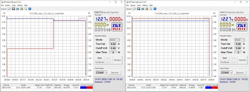
The warm-up test was run at 3 A and 6 A. Then I tried raising the current to 6.5 A, which triggered the protection. I then set it to 6.25 A, and the power supply shut off after 8 minutes.
So in practice, with the power supply warmed up, the protection current is set to around 6.2–6.3 A, and there's no need to change anything. The test was a little inconclusive, of course, but I think I did reach the limit in the end; it simply won't go any higher.
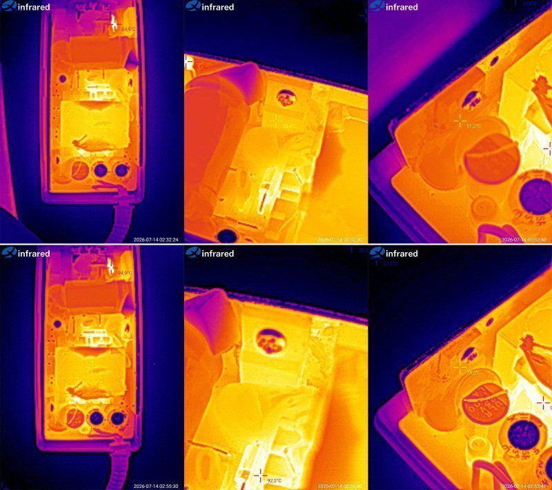
Temperatures at these currents:
3 A — transformer 59 degrees, transistor 58, rectifier 51 degrees.
6 A — transformer 83 degrees, transistor 85, rectifier 75 degrees.
In my opinion, these are excellent results. There's plenty of headroom for a rise in ambient temperature. Technically, this power supply could easily handle 6.5 A, but no more; beyond that, it would simply hit the limits of the synchronous rectifier.
And here are a couple more models built around the same power supply.
First up is the 12 V, 8 A version. The manufacturer originally rates it at 10 A, but we decided it would be better to offer two models: the basic 10 A model is labeled as 8 A, and then there's the 10 A version.
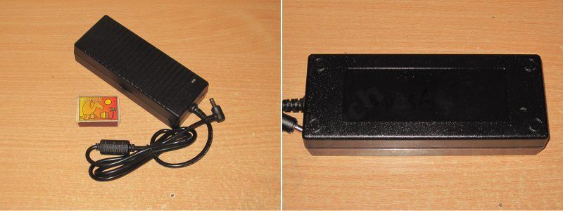
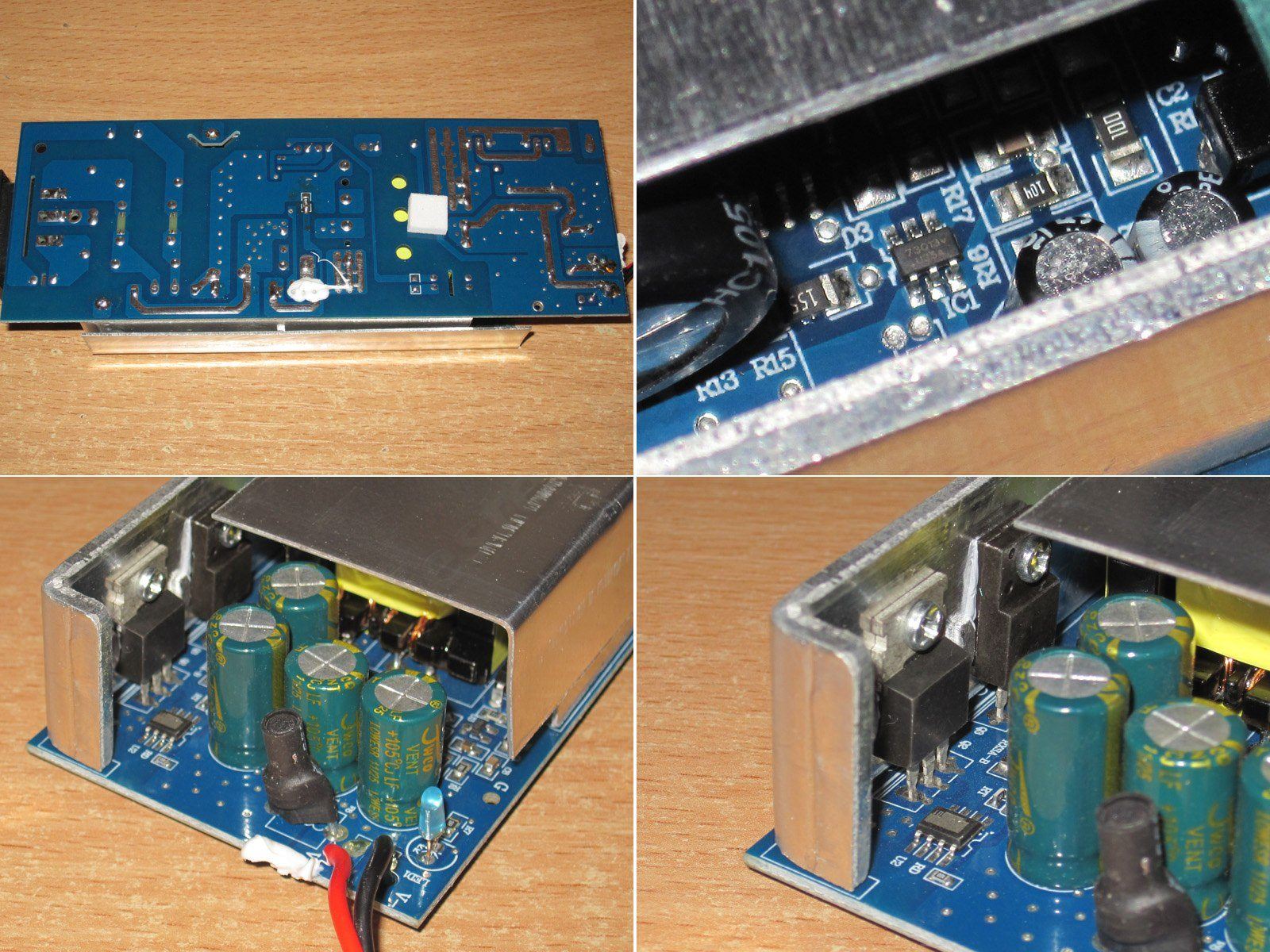
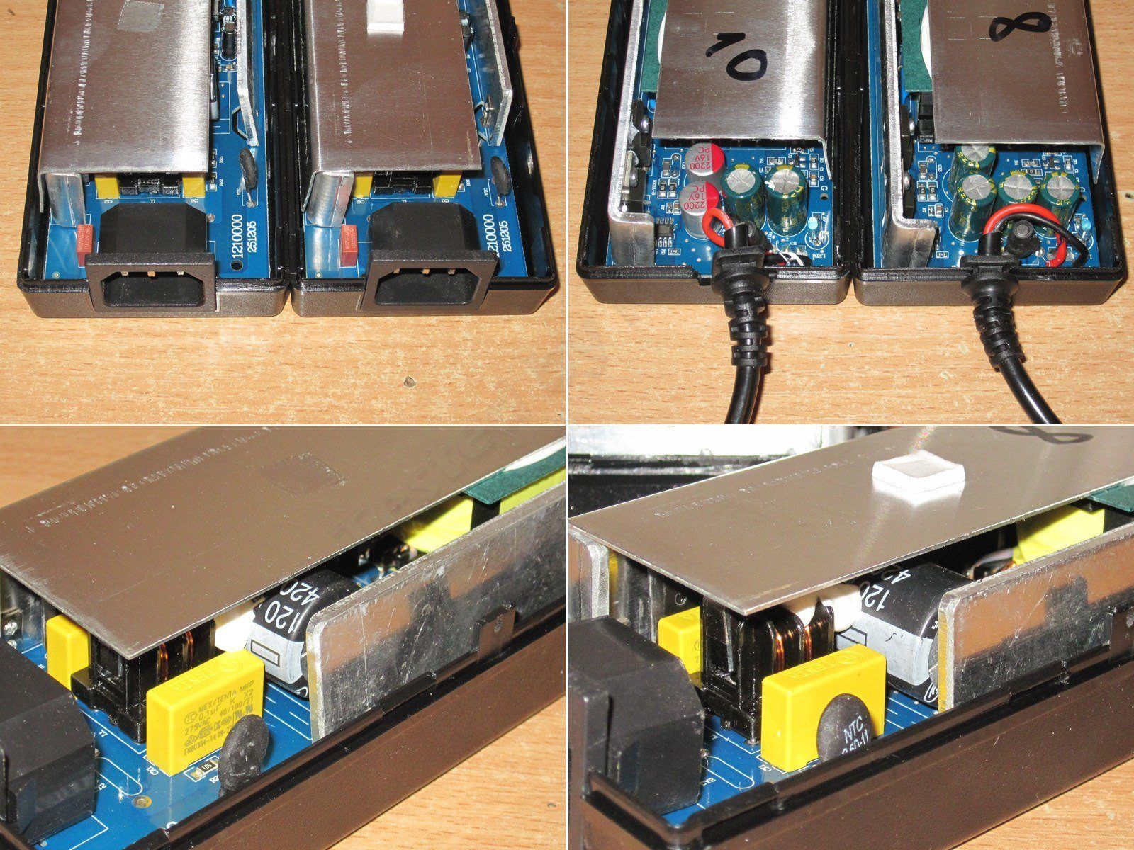
The case is more substantial here, and the board is made of fiberglass rather than phenolic paper. Though I think I may have already reviewed this power supply, but I could be mistaken.
Anyway, even a quick glance makes it clear that this is a noticeable step up from the previous models.
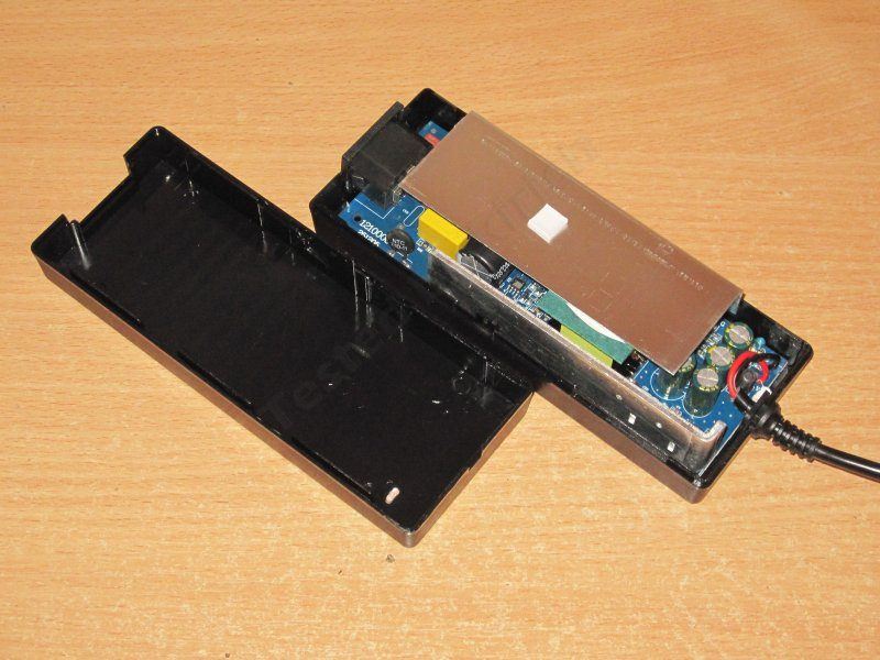
I didn't remove the heatsink; there's not much point, and you can already see that this one also uses a synchronous rectifier, which was there from the start.
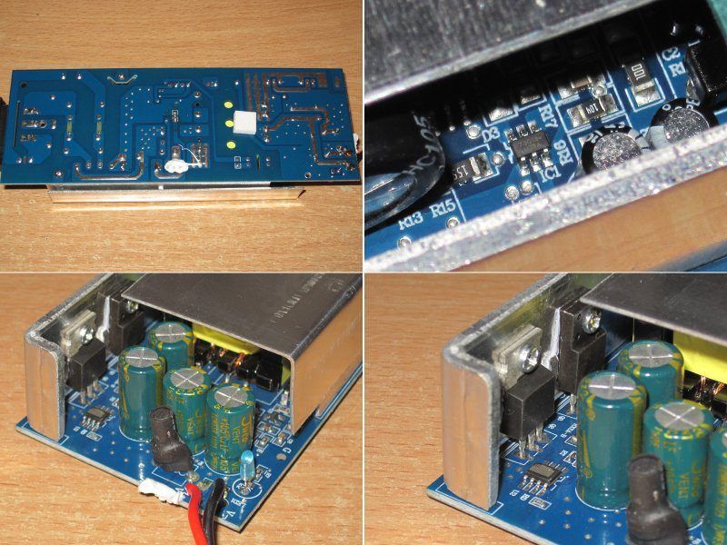
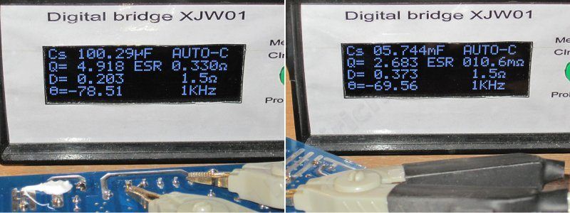
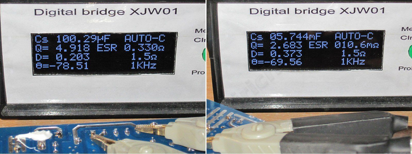
The input capacitor is marked 120 µF, but measures about 100 µF. The output capacitance is 5750 µF, which is generally enough for 100 W.
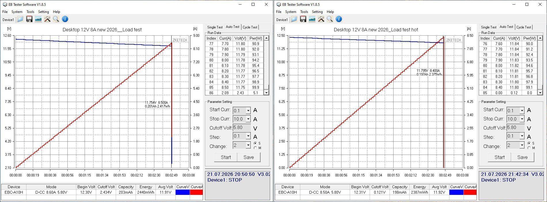
We deliberately set the overcurrent protection to 8.5–8.4 A, both cold and hot. The idea was to fill the niche for 8 A models.
The ripple looks great here: 60 mV at 8 A, with no spikes at all. Five stars.
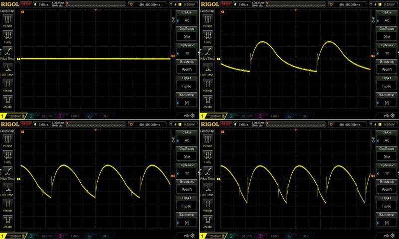
The low-frequency ripple looks good too, with nothing to complain about.
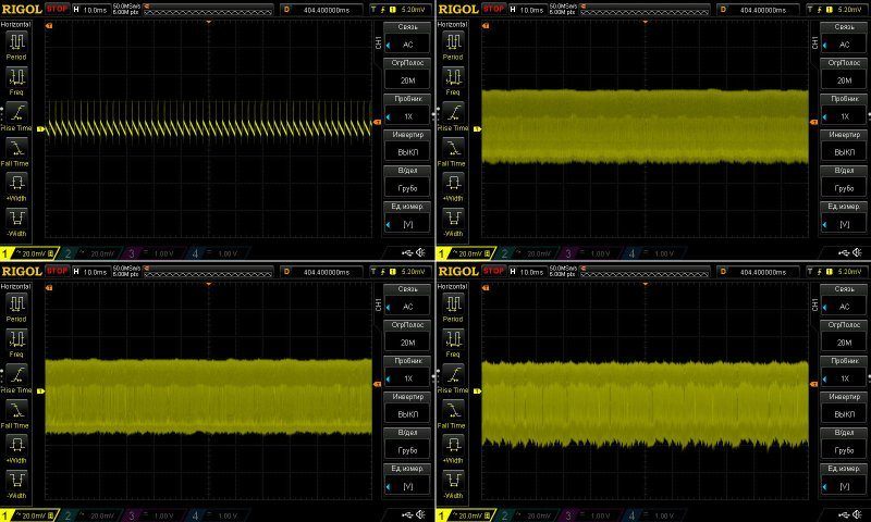
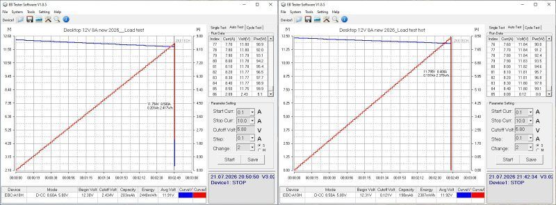
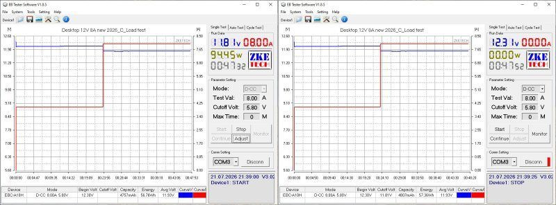
I tested it at 4 A and 8 A; there's no point going higher, since the protection threshold is only 5% above the rated current.
The voltage drops by half a volt under load because of the voltage drop in the wires. To be fair, though, the wires here are pretty good. The temperature-related variation is minimal, just about 10 mV.
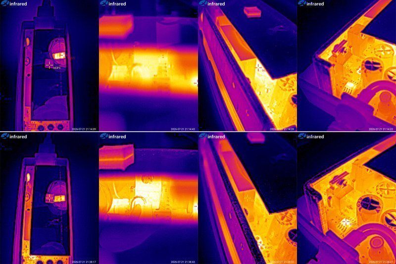
And here are the temperature test results.
4 A — transistor 51 degrees, transformer 52 degrees, rectifier about 50.
8 A — transistor 79 degrees, transformer 74, rectifier 76. The synchronous rectifier controller gets hot too, reaching almost 90 degrees.
Overall, all the temperatures are within the normal range; there's no sign of overheating.
The 10 A model is almost identical, though there are, of course, a few small changes.
I should mention that the factory offered two new models to replace this one, rated at 10 A and 12 A. I tested them and found that their new 12 A power supply runs hotter at 10 A than this older model does at the same 10 A. Naturally, we turned them down; there was no point.
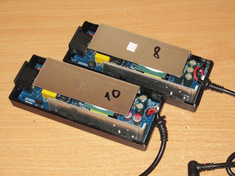
The actual differences are the output capacitors—the 10 A version has two 2200 µF, 16 V polymer capacitors—the different protection threshold, and a few other minor details I can't remember now.
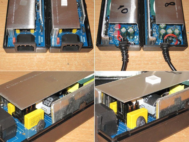
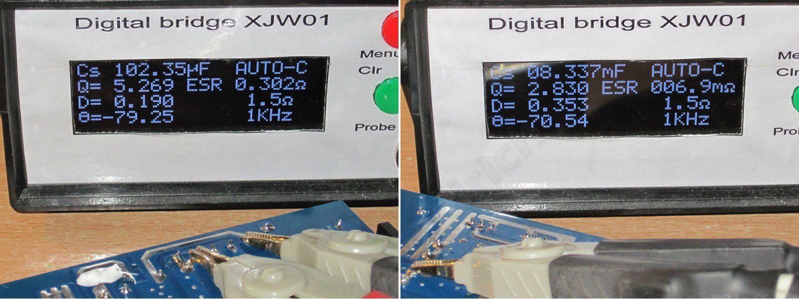
The input capacitor is about the same, 100 µF, while the output capacitance is higher now, around 8300 µF, and the ESR is lower too.
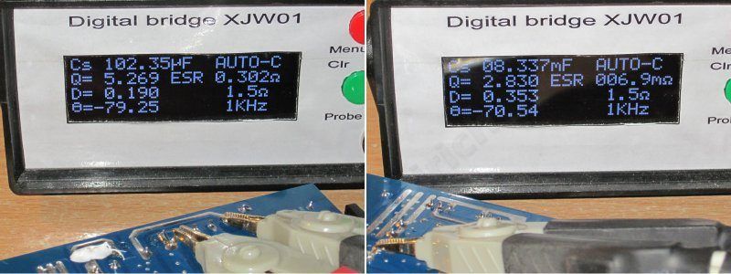
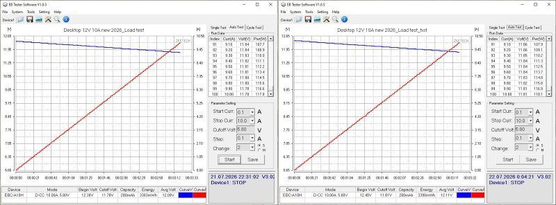
The protection threshold is above 10 A, so I couldn't check it using the main load.
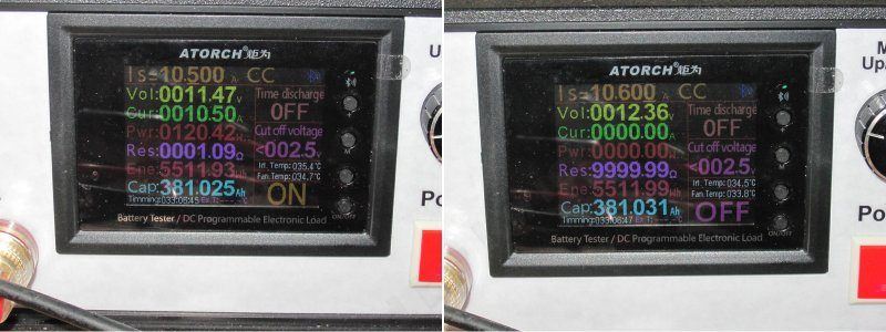
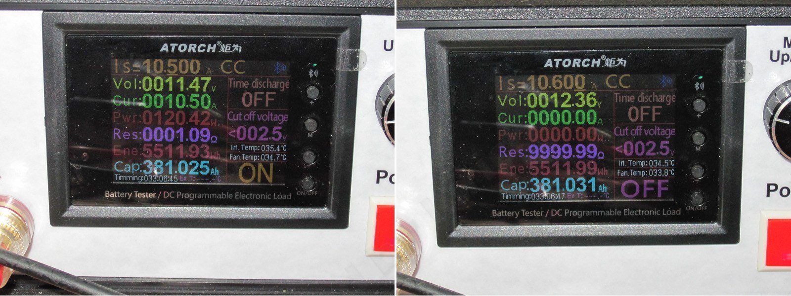
While checking the ripple, I also tested the shutdown current. It turned out that the power supply still works normally at 10.5 A, but shuts down at 10.6 A, which is more than acceptable. Initially, I thought this model's current was too high.
Well, the ripple here is really excellent: at 10 A, it's around 25 mV. There are some "spikes" with a total amplitude of up to 50 mV, but they can be ignored.
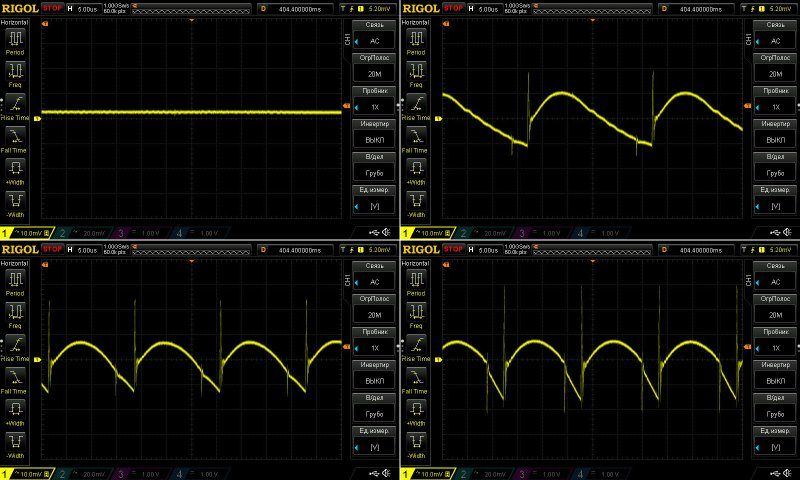
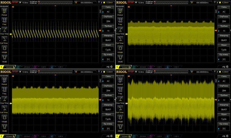
The low-frequency ripple is also fine. There's a slightly odd "fuzz," but compared with the overall scale, it's really negligible.
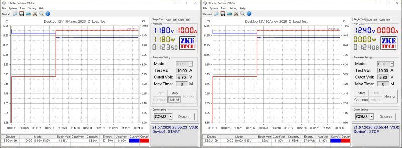
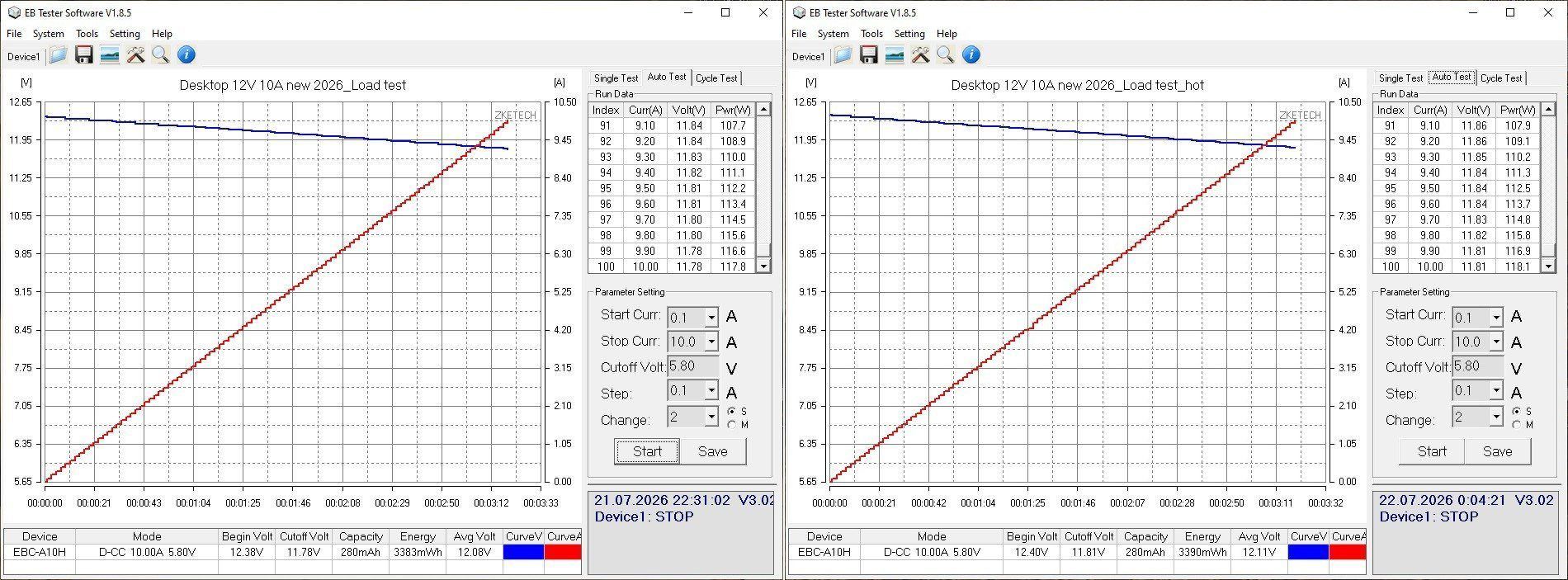
The test was run at 5 A and 10 A and took almost an hour and a half in total.
The output cable has a decent cross-section, but it still drops a full 0.6 V under full load. At 10 A, that's 6 W, which is a lot. The cable gets noticeably warm during operation, as does the plug.
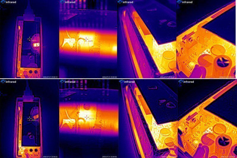
And, of course, component temperatures.
At 5 A: transistor 63 degrees, transformer 58 degrees, rectifier 56 degrees.
At 10 A: transistor 118 degrees, transformer 102 degrees, rectifier 105 degrees.
I tried to record the maximum temperatures in each case. I was a little surprised by how hot the components got at 10 A.
So, in practice, this power supply should have no trouble running continuously at 8–9 A, but I wouldn't use it continuously at 10 A.
Conclusions.
I hadn't reviewed any of the 24 V power supplies shown here before, but I do have some concerns about the low-power models. One seems to handle 2 A; the other is supposedly rated for 2 A but in reality is probably closer to 1 A. I think they still need some work.
The 2 A and 3 A desktop models are noticeably better, but it's clear that the factory tried to bring them in line with our recommendations for the 12 V models. I have concerns about ripple on the 2 A model. I don't think I had any complaints about the 3 A version: it has a polymer output capacitor and a synchronous rectifier.
The 12 V models are a little more predictable. I hadn't reviewed the 1 A and 2 A units from these revisions before, and they have the most issues. The 1 A version has a regular capacitor instead of the correct Y capacitor, which is unsafe. The 2 A version showed signs of overheating at maximum power.
The 3 A, 4 A, and 5 A versions are all the same power supply, with varying degrees of modifications and corrections, so they perform more or less alike: no overheating, a reasonable level of electrical safety, and low ripple. These models were made to our recommendations.
The 6 A version is very similar and was also made the way we wanted, so there are no issues with these models.
The higher-power versions are a little more complicated. I have no complaints at all about the 8 A version. The 10 A version runs closer to its limits. Even reducing the current to 9–9.5 A makes everything completely stable, but that's the only issue. The build quality and all the other parameters are excellent; I especially want to point out the very low ripple on the 10 A version.
Yes, I focus on temperatures at 100% of the rated load, but we all know that power supplies shouldn't be run continuously right at their maximum power. Still, as you could see in the review, the 3–8 A versions can run continuously at 100% load without any trouble. And that's exactly what we're aiming for.
Someone once asked me in the comments: what's the point of these reviews if the Chinese manufacturers will send something different next time? That's not the point at all. The whole idea is that we shouldn't have to depend on whatever they send us; instead, we should know exactly what we'll get, because the factory makes all the necessary modifications to meet our requirements.
That's also why we're considering making our own power supplies, most likely in Ukraine. To keep costs down, we may use some ready-made components—at least the most troublesome one, the transformer, and the enclosures. Ordering molds is expensive :(
That's probably all for today. This turned out to be quite a long one; I hope it was useful, and thanks to Vitaly for the productive collaboration :)
I'll add links to these power supplies in the store later, as they become available.
Most of the models here today are, in fact, ones sent after being modified to meet our requests.
A reminder: to keep up with new blog posts, I recommend following me on Instagram. I'll post notifications about all new posts there, and might also write about something interesting from time to time: link to my account
You can also subscribe to updates and new articles on the Telegram channel - https://t.me/KirichBlog Just a note: discussion of reviews and articles is enabled on the channel, and you can also just chat. I recommend it.
Just to put things in perspective, there are several ways to get something of decent quality at a reasonable price.
1. Search through dozens of factories and hundreds of power supplies.
2. Find a few factories willing to make power supplies according to our improvement recommendations.
3. Design and manufacture the power supplies ourselves.
The first option is mostly a dead end: first, it's a lot of work, and second, manufacturers like these often change the internals on the fly.
The second option is much more worthwhile, especially if the factory is genuinely interested in working with us and has competent engineers.
The third option is more expensive, but even more predictable. It's still under consideration.
To get ahead of myself, this review turned out to be very long as it is, so I didn't measure efficiency. But I'll say that this was one of the parameters we were trying to improve. The point is that efficiency is directly related to heat generation, which I think is obvious.
But what affects efficiency? A whole lot of things.
The input capacitor's capacitance—not much, but it still matters.
The combination of the PWM controller and high-voltage transistor.
The snubber circuit design and transformer quality; sometimes a poor design can undo all the improvements.
The output diode—ideally, a synchronous rectifier. This can give a noticeable increase in efficiency.
The output capacitors. ESR is the main factor here. I experimented with this once, and yes, replacing regular capacitors with polymer ones also increases efficiency a little, while reducing ripple and improving reliability.
The output inductor that filters ripple. It's best to choose one with plenty of current headroom, so its DC resistance has less effect.
We experimented with many of these things.
Today's review covers 4 24 V power supplies and 10 12 V power supplies.
I'll start with the 24 V versions. These are also pre-production samples, but I hadn't seen them before, so I'll send the manufacturer a report on them.
Two power supplies are marked 24 V, 2 A, in the "adapter" form factor, and two are desktop models. There are three in the first photo because I initially thought the two adapters were identical.
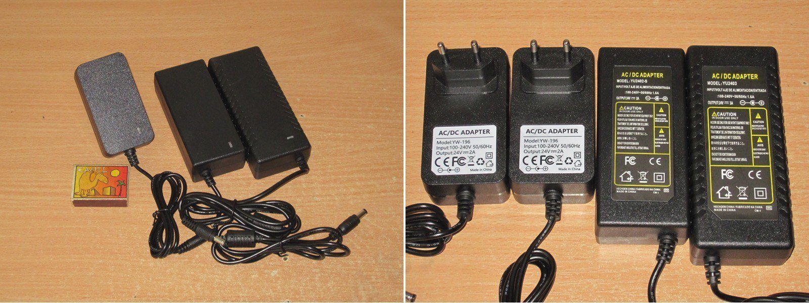
1. The model marked 24 V, 2 A. The case is held together with clips, which is nice. In fact, all the power supplies in this review have clip-together cases.
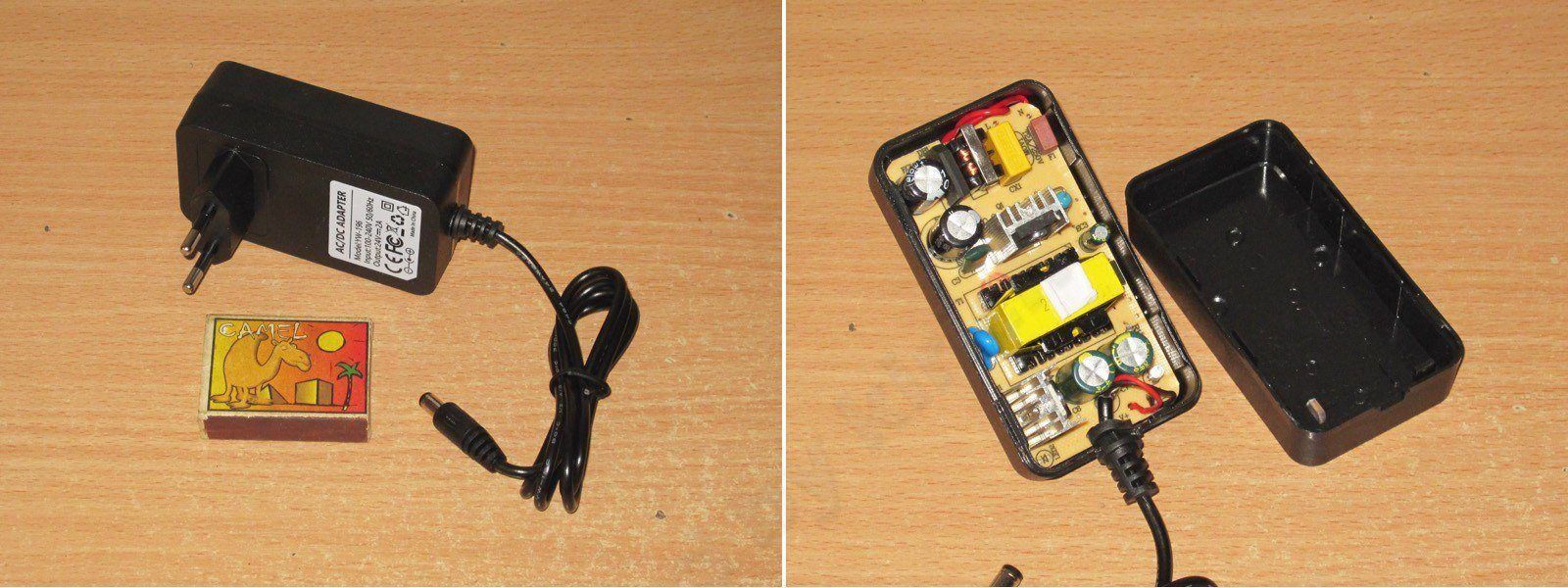
It looks pretty good: heatsinks on the transistor and diode assembly, an input filter, and a small output inductor. Overall, quite acceptable.
The only odd thing I noticed right away was that there are two input capacitors, 10 and 22 µF, but both are rated for 400 V and are exactly the same size...
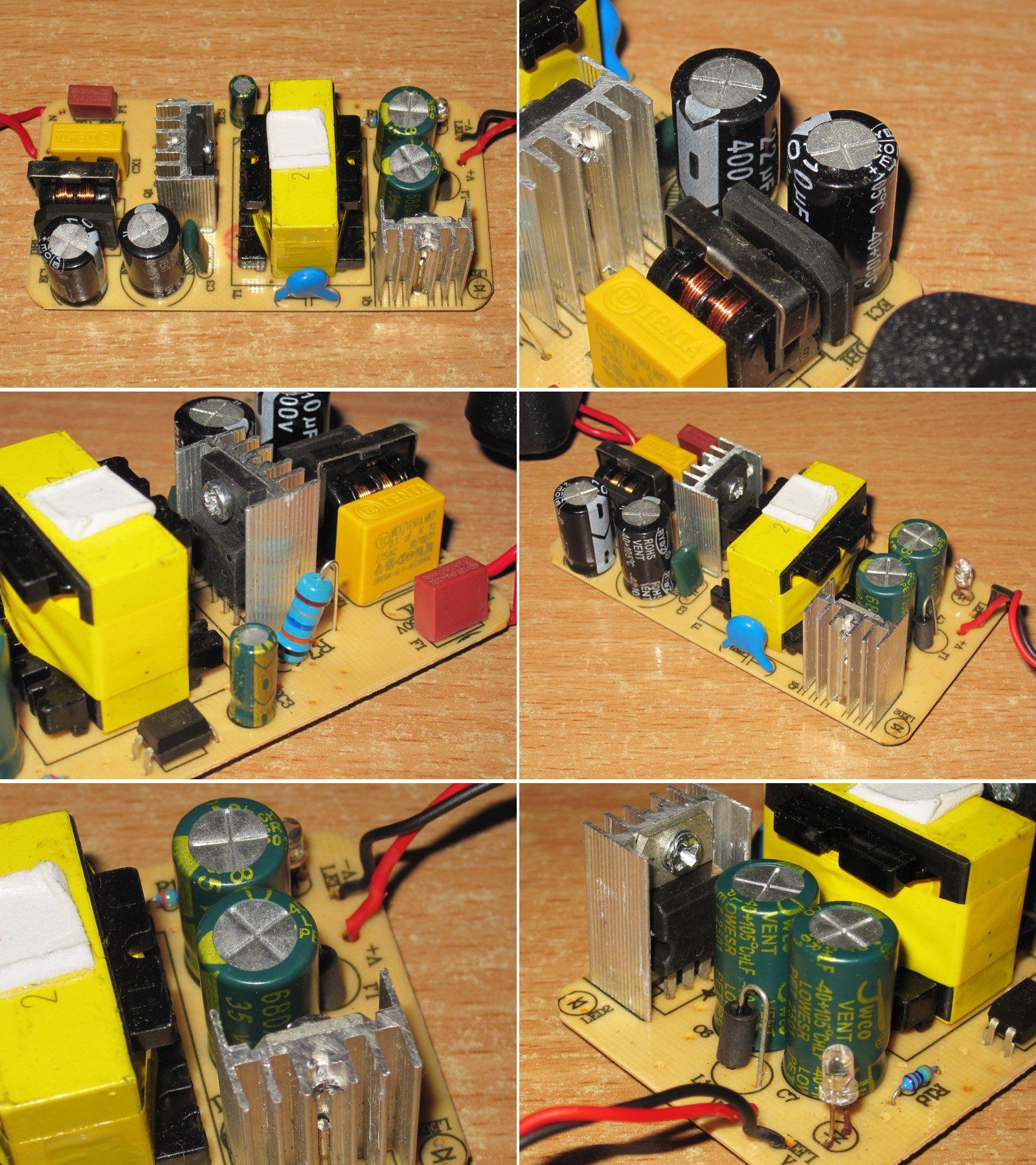
No concerns about electrical safety: the clearance between the primary and secondary sides is sufficient, there's a Y-rated capacitor between the windings, and there are spark gaps under the input inductor.
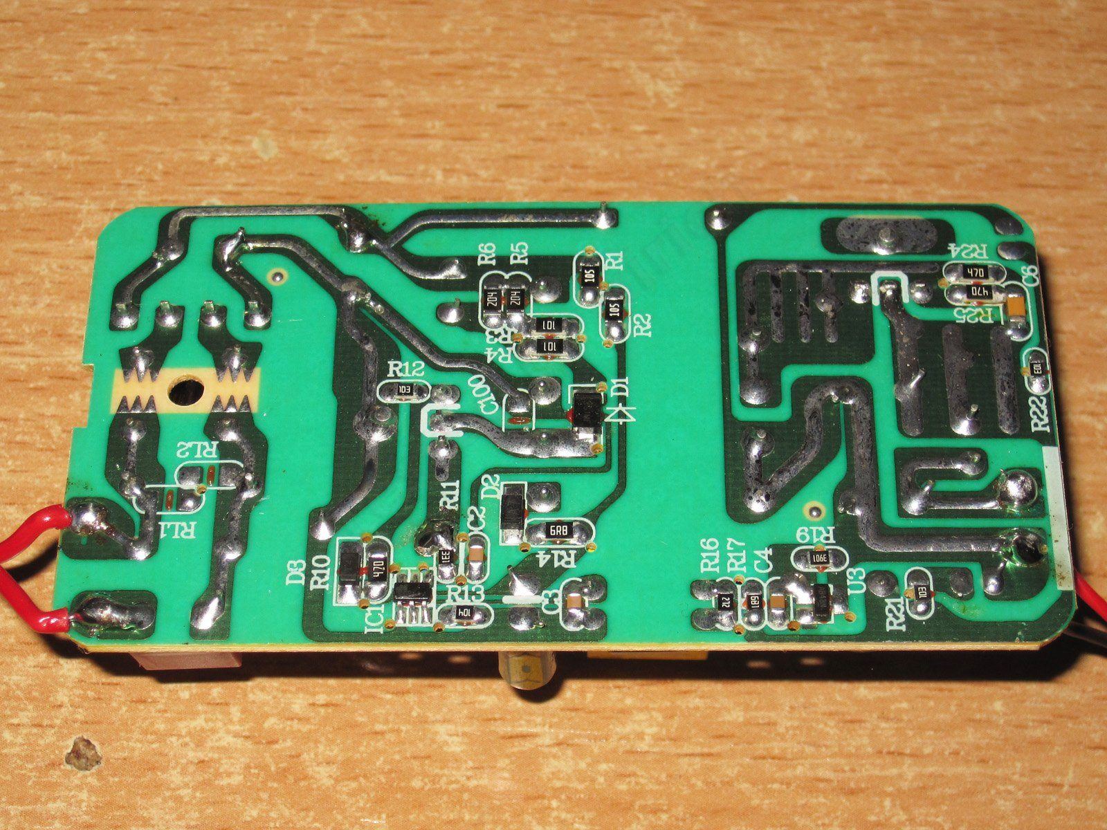
The input capacitors have a total capacitance of 27 µF, which is a bit low for 48 W. On the output there are two 680 µF, 35 V capacitors; their measured combined capacitance is about 1200 µF, which is acceptable.
Remember I mentioned the odd input capacitors? I suspected they might actually be a pair of 15 µF capacitors with different markings, but no—the capacitance of one really is close to 22 µF and the other's close to 10 µF, despite them being the same size. I have doubts that the 22 µF capacitor is actually rated for 400 V, so we'll follow up on this with the factory.
The protection trips at around 2.8 A, which is far too high for this power supply. It's entirely possible to load it to 2.5 A and have it fail from overheating. We'll address this too.
Ripple is pretty good: around 70 mV at high frequency. That's especially good considering this is a 24 V power supply.
Here and below, ripple is measured under these conditions: no load, then at 33, 66, and 100% load; the probe input has two capacitors in parallel, 1 and 0.1 µF; measurements are taken directly at the PCB output pads, i.e. Most of the high-frequency ripple won't make it to the load.
I also have no complaints about the 100 Hz ripple, especially considering that the input capacitors are below their rated capacitance.
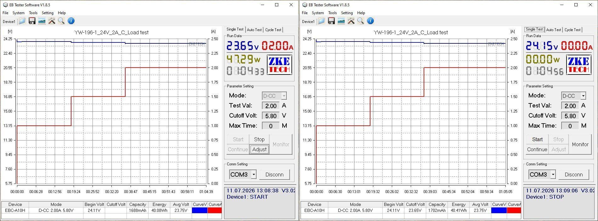
The thermal test was carried out in three stages, at load currents of 1, 1.5, and 2 A. Even though the voltage was measured after the output cable, it remained quite stable.
The voltage has a slight positive temperature coefficient. At the bottom of the screenshot on the right is the no-load voltage at the start of the test: 24.11 V. At the top right is the no-load voltage after warm-up: 24.15 V.
And now for the most important part: the temperatures.
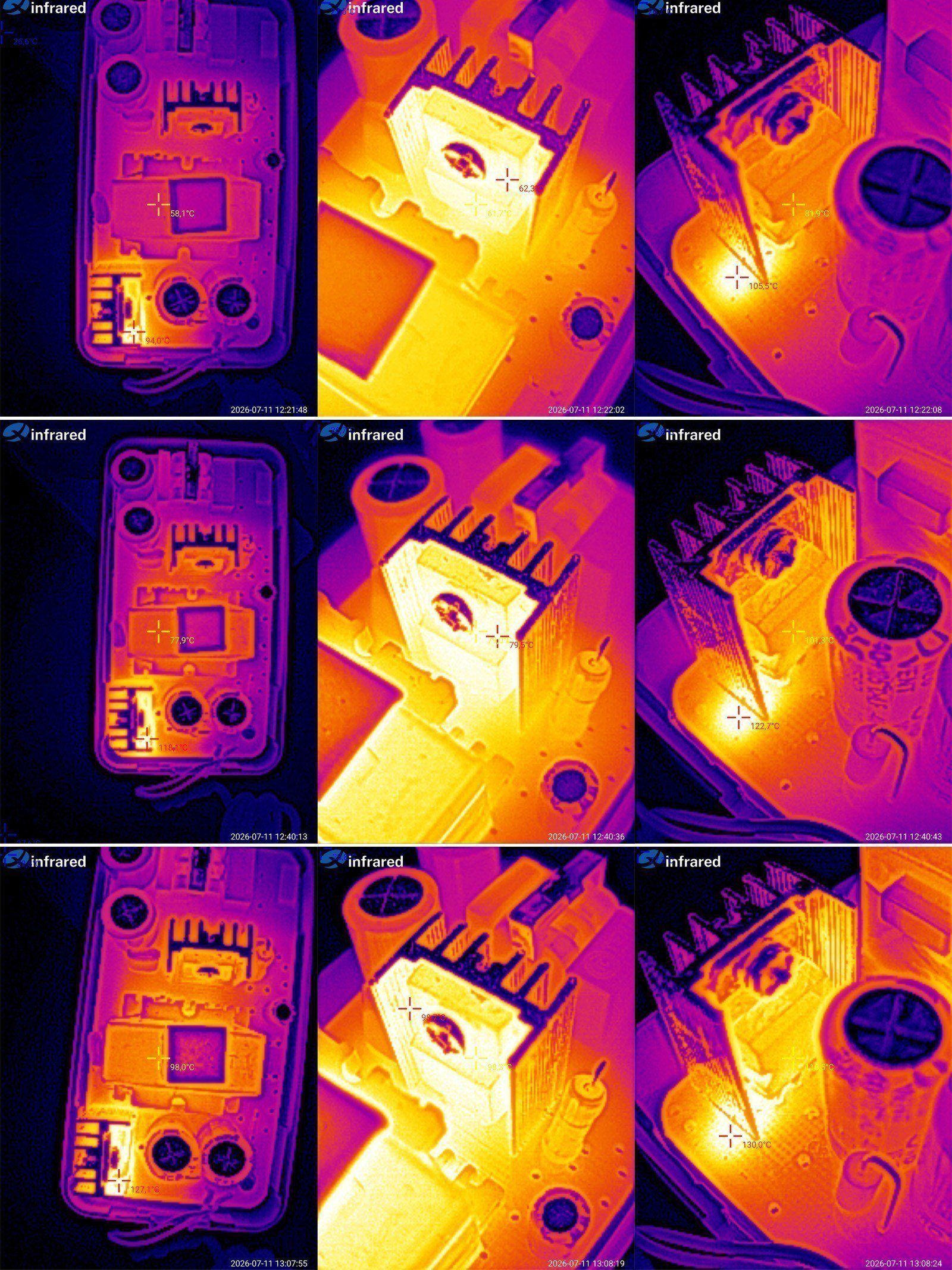
At 1 A: transformer 58°C, transistor 62°C, output diode assembly 82°C.
At 1.5 A: transformer 78°C, transistor 80°C, diode assembly 101°C.
At 2 A: transformer 98°C, transistor 99°C, diode assembly 116°C.
Personally, I think that in its current form, the continuous output current should be no more than 1.5 A (36 W). Beyond that, the output diode assembly overheats. The transformer and transistor can handle an output current of 2 A, but with very little headroom.
I should also point out that the snubber under the output diode assembly gets noticeably hot. You can see that the board in this area heats up to 130°C. I think that if this issue is addressed (by recalculating the snubber values and moving it a little farther away), the diode assembly temperature will drop.
Logically, this should be the more powerful version, but there's a catch.
In the photo above, I showed that I received two power supplies that looked absolutely identical, and even thought the manufacturer had simply sent two units for testing. What's more, I asked Vitaly about it—he's the one who sent me all these power supplies.
But in the end, taking them apart cleared things up: the power supplies are identical only on the outside; inside, they're completely different.
The second test unit is on the left; the one I showed above is on the right.
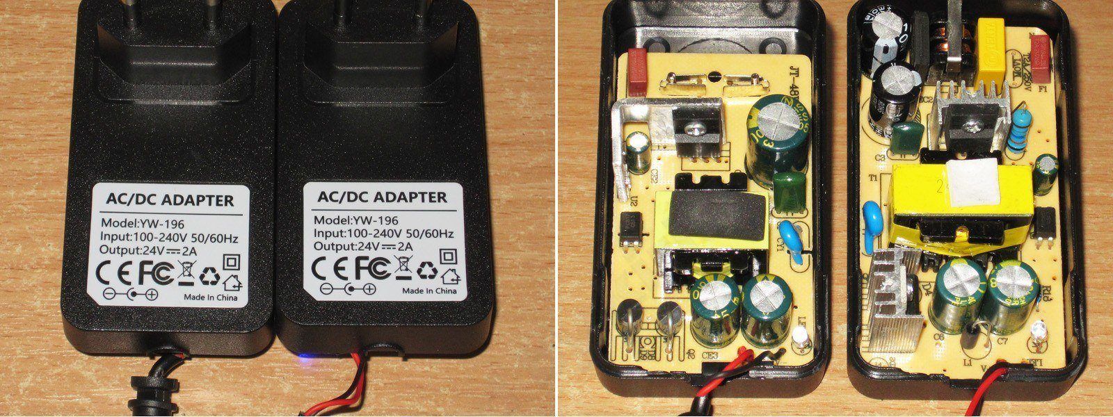
The cost-cutting is impossible to miss; it's coming out of every seam. There's no input filter, the transformer is about half the size, and the output diodes are standard ones rather than an assembly mounted on a heatsink.
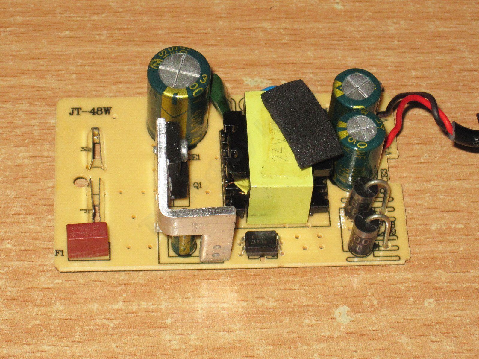
The transistor is installed at an odd angle, and the PWM controller capacitor is right up against the heatsink. The input capacitor is at least 33 µF, so that's just about acceptable.
They used the correct interwinding capacitor and even cut a slot underneath it. On the output side, as with the previous model, there are a couple of 680 µF, 35 V capacitors.
So, basically, it already looks like a budget version of a decent power supply. You can tell right away that it definitely won't deliver as much power as the previous one.
That said, I have no complaints about the circuit board. The soldering is neat, and there are safety slots.
The input and output capacitances are more or less the same as on the previous model.
But the overcurrent protection is set to a ridiculous 3.2 A when cold and 3.1 A when hot. Since this power supply is clearly weaker than the previous one, even from the outside, the protection current should be cut roughly in half right away.
The high-frequency ripple is about the same as on the previous unit, around 75–80 mV, not counting the spikes.
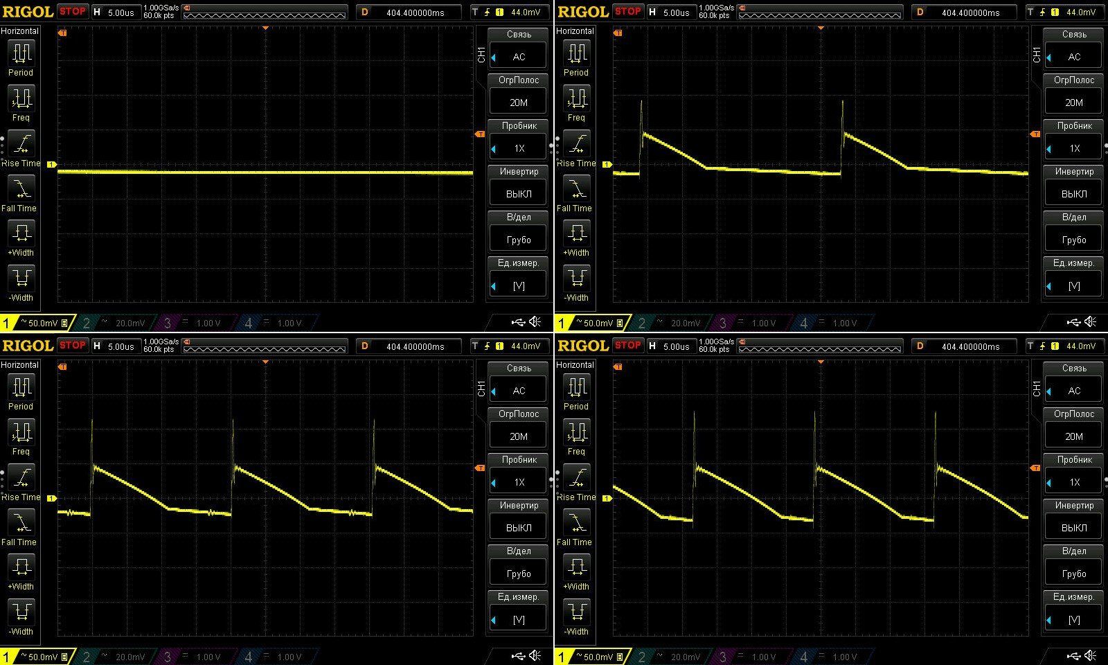
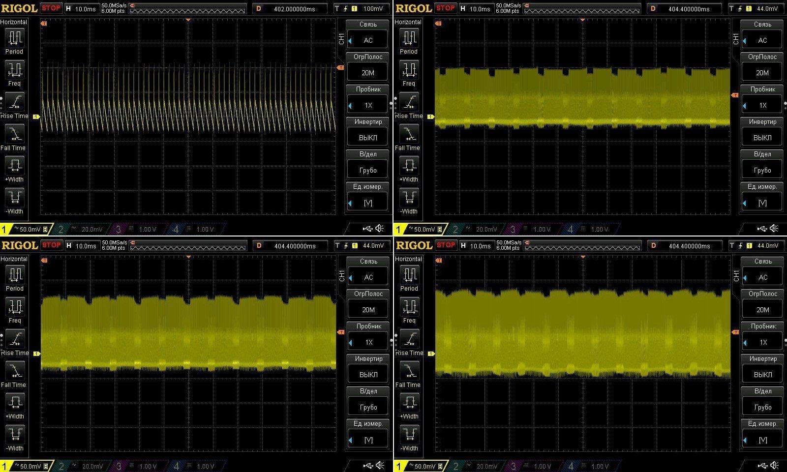
I don't really have any complaints about the 100 Hz ripple, especially considering how clearly budget-oriented this unit is.
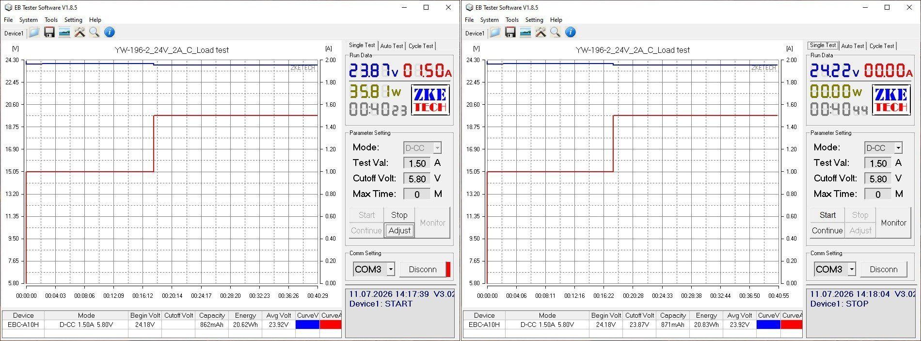
The test was carried out in just two modes, at 1 A and 1.5 A. I think you've already guessed why.
The voltage has a slight positive temperature coefficient, but it's negligible. I also had no complaints about voltage regulation: the entire voltage drop under load was across the output cable.
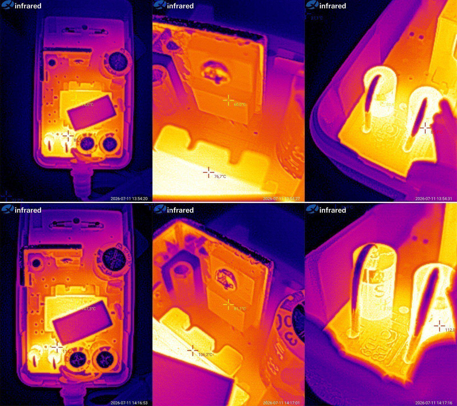
And now for the temperatures.
At 1 A: transformer 76°C, transistor 60°C, output diodes 85°C.
At 1.5 A: transformer 107°C, transistor 81°C, diodes 112°C.
As you can see, the transformer is the weak point. At just 1.5 A, its temperature has already gone over 100°C, which is far too high. I think the power supply's actual output current is 1 A. It can probably handle 1.2 A, but even 1.5 A is too much.
My guess is that this was originally a 2 A power supply, and they simply happened to use a case from the 24 V, 2 A model for the sample. Let's take a closer look.
The third power supply is also 24 V and 2 A, but in a desktop form factor. Cooling is usually better in this type, simply because the case is larger, though there are some caveats.
The thing is, if the cases are the same size, the adapter-style version (the kind that plugs directly into the wall) cools better because it essentially hangs in the air. A desktop unit cools less effectively because it sits on a surface, which restricts airflow. But that's when the cases are roughly the same size.
This case is clearly larger, which should make up for the factors mentioned above.
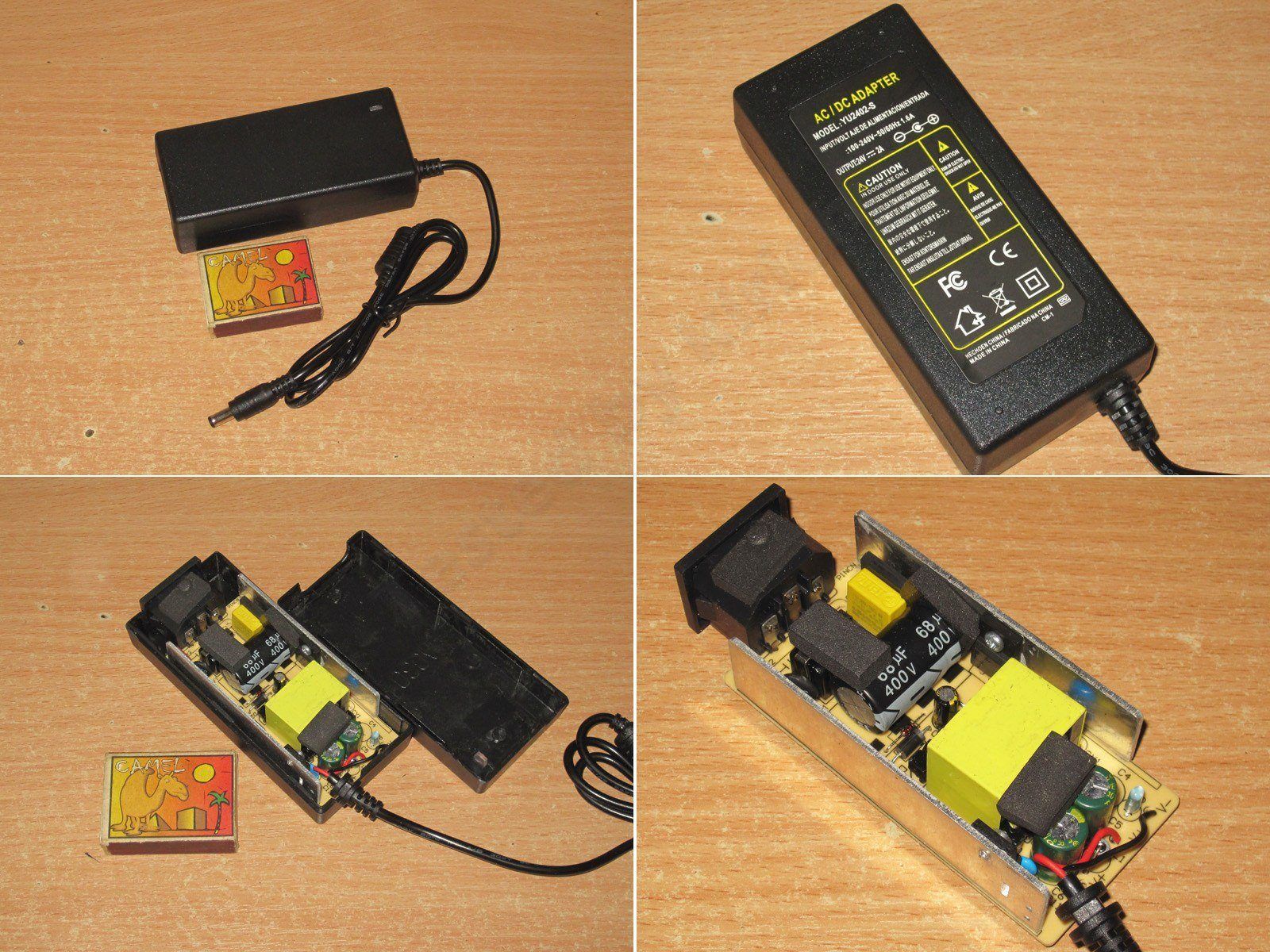
It has an input filter, a thermistor, and a Y capacitor. On the output, though, for some reason there are two 470 µF, 35 V capacitors; the previous units had 680 µF ones. There's also a small inductor to reduce ripple, though one like this is more likely to suppress very short spikes.
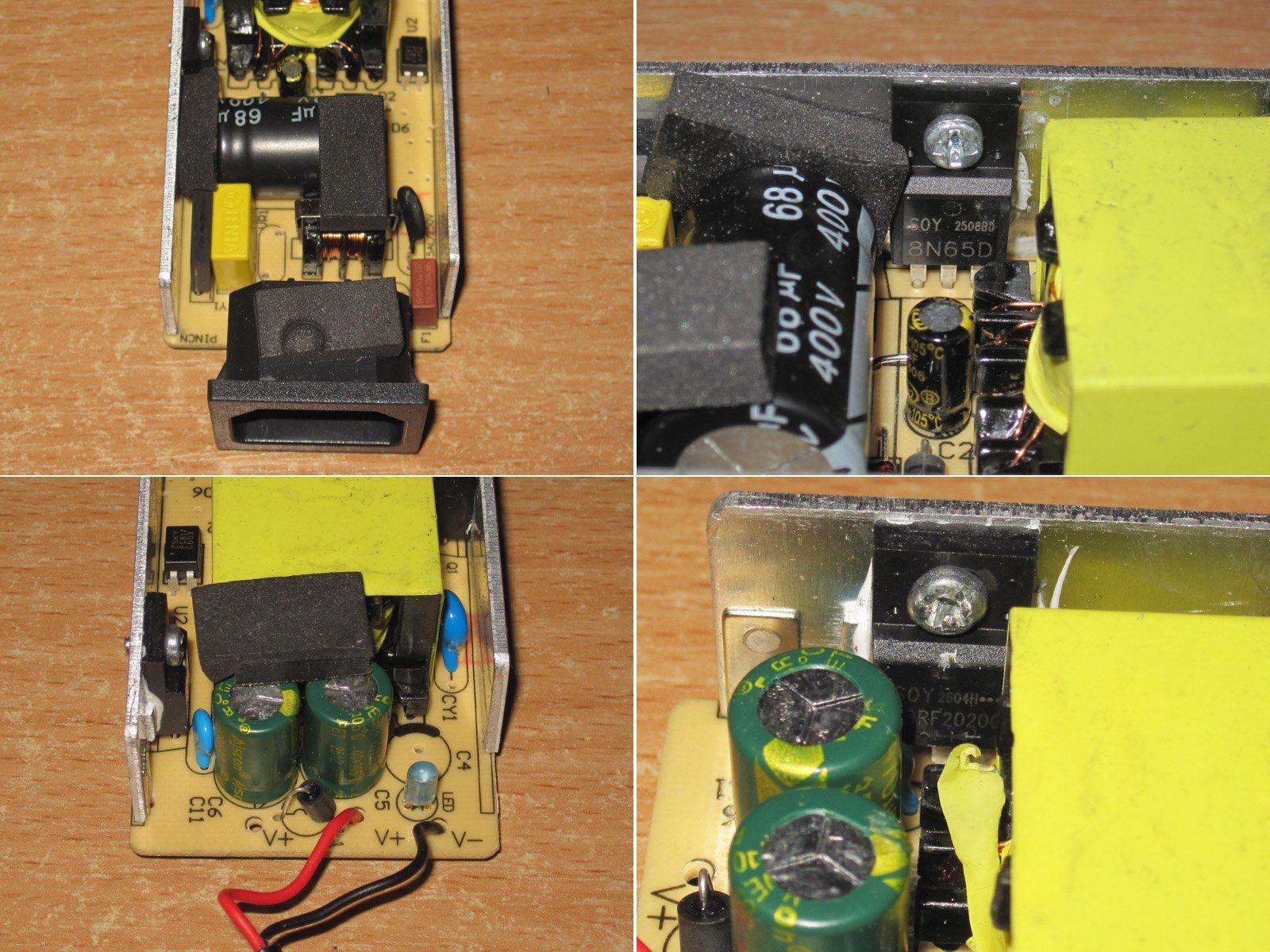
Overall, I have no complaints about the board. The clearance between the primary and secondary sides is sufficient, and the soldering is neat too—well, almost.
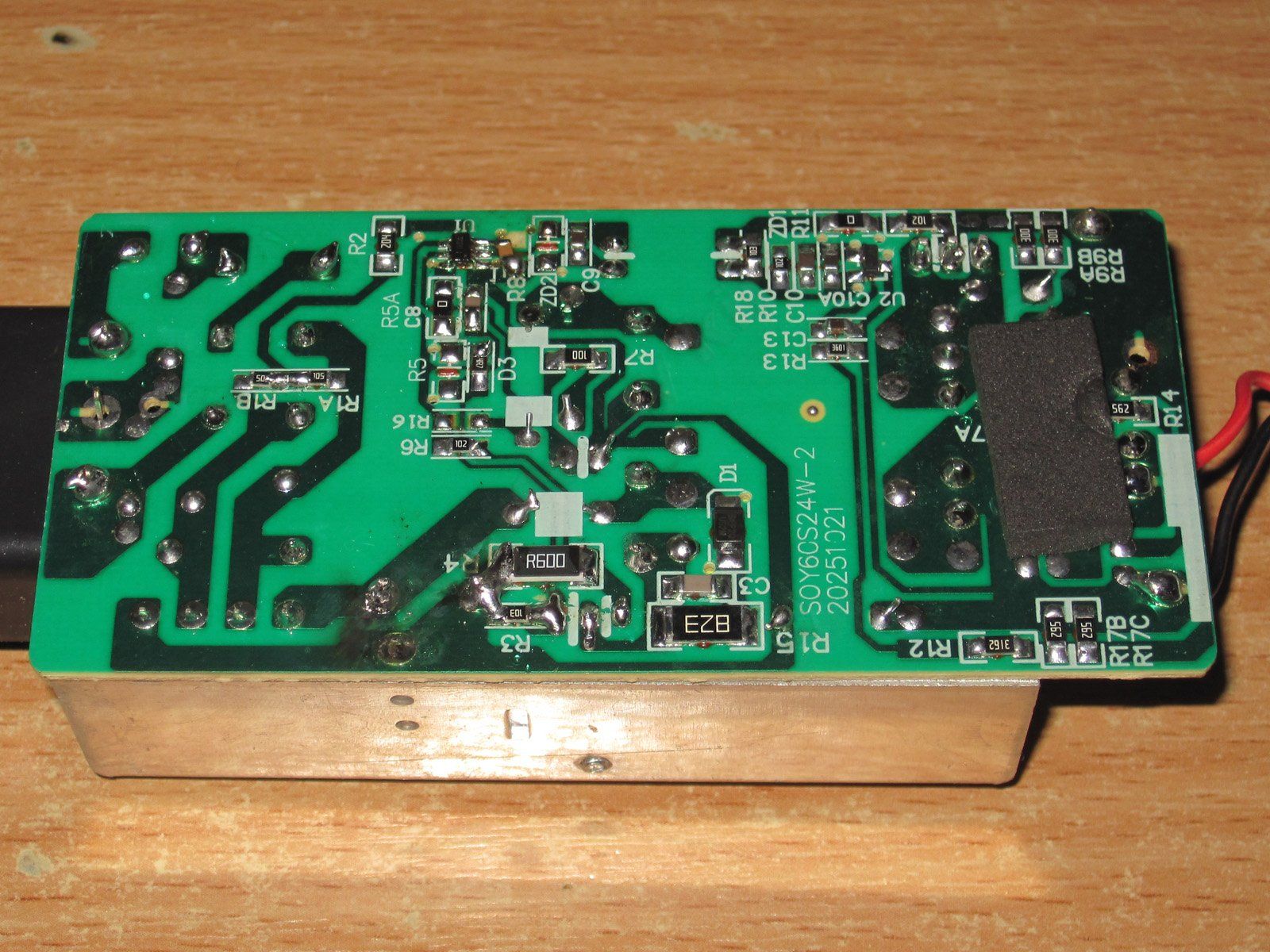
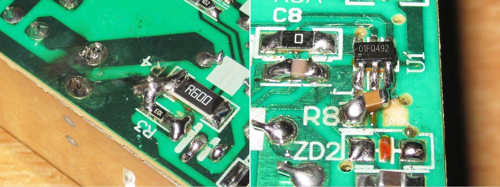
But then I noticed a few oddities: messy soldering on the shunt, soot around the capacitor leads, and a capacitor near the PWM controller soldered on crooked.
But actually, that's normal. The soot probably came from shorting the input capacitor, and the shunt was being adjusted to find the right value—in other words, this is clearly a prototype. None of this will be present in the production version.
And yes, you can tell the factory made a test sample specifically, rather than just grabbing the first suitable unit they could find.
About 58 µF on the input, which is excellent for 48 W. The output has 820 µF; I'd have liked to see more, at least as much as in the previous units, which had two 680 µF capacitors.
The protection is set correctly, at 2.3 A, and here too you can see that they were experimenting with the shunt.
The ripple, though, isn't great. At high frequency and full power, it's around 300–400 mV—not a complete disaster, but I think replacing the output capacitors with higher-capacitance ones and fitting an inductor with higher inductance could cut it by a factor of two. Let's write down the recommendations, then check again.
At 100 Hz, everything looks fine, apart from the generally high level.
The test was run at currents of 1, 1.5 and amps. I have no complaints here: the voltage drops under load, but not critically. And as a reminder, this is essentially the voltage drop across the cable. There is some dependence on warm-up, but it is very small, around 30 mV.
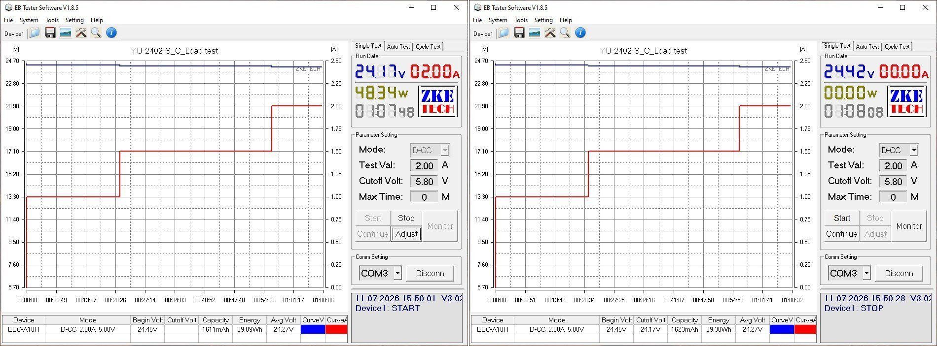
Now for the temperatures.
1 A — transformer 55, transistor 55, diode assembly 57 degrees
1.5 A — transformer 74, transistor 67, diode assembly 73 degrees
2 A — transformer 82 degrees, transistor 78 degrees, diode assembly 85 degrees.
The thermal camera picked out other spots as the hottest objects, while the readings in the center blend into the background and may not be visible. But trust me, they are correct.
In my opinion, these are excellent results. The only real complaint about this power supply is the elevated ripple, but that is relatively easy to fix.
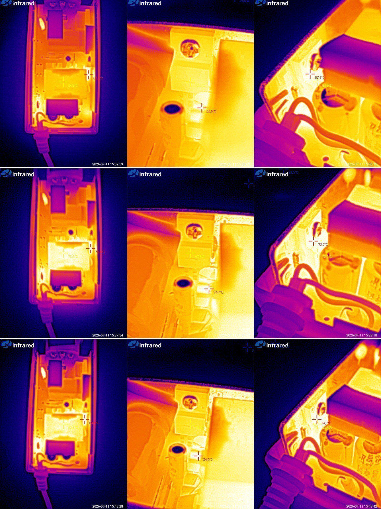
The fourth model is 24 V, 3 A. In my opinion, this one is a little more interesting, especially in terms of its “internals.”
At a glance, it is a standard power supply, but it is worth noting that 24 V at 3 A is 72 W. In terms of the 12 V models, that would be 6 A, which is already quite a lot.
Inside the case there is a steel cover glued to the transformer, which should improve its cooling somewhat. I had to remove it for inspection, though, so the test results may be slightly affected.
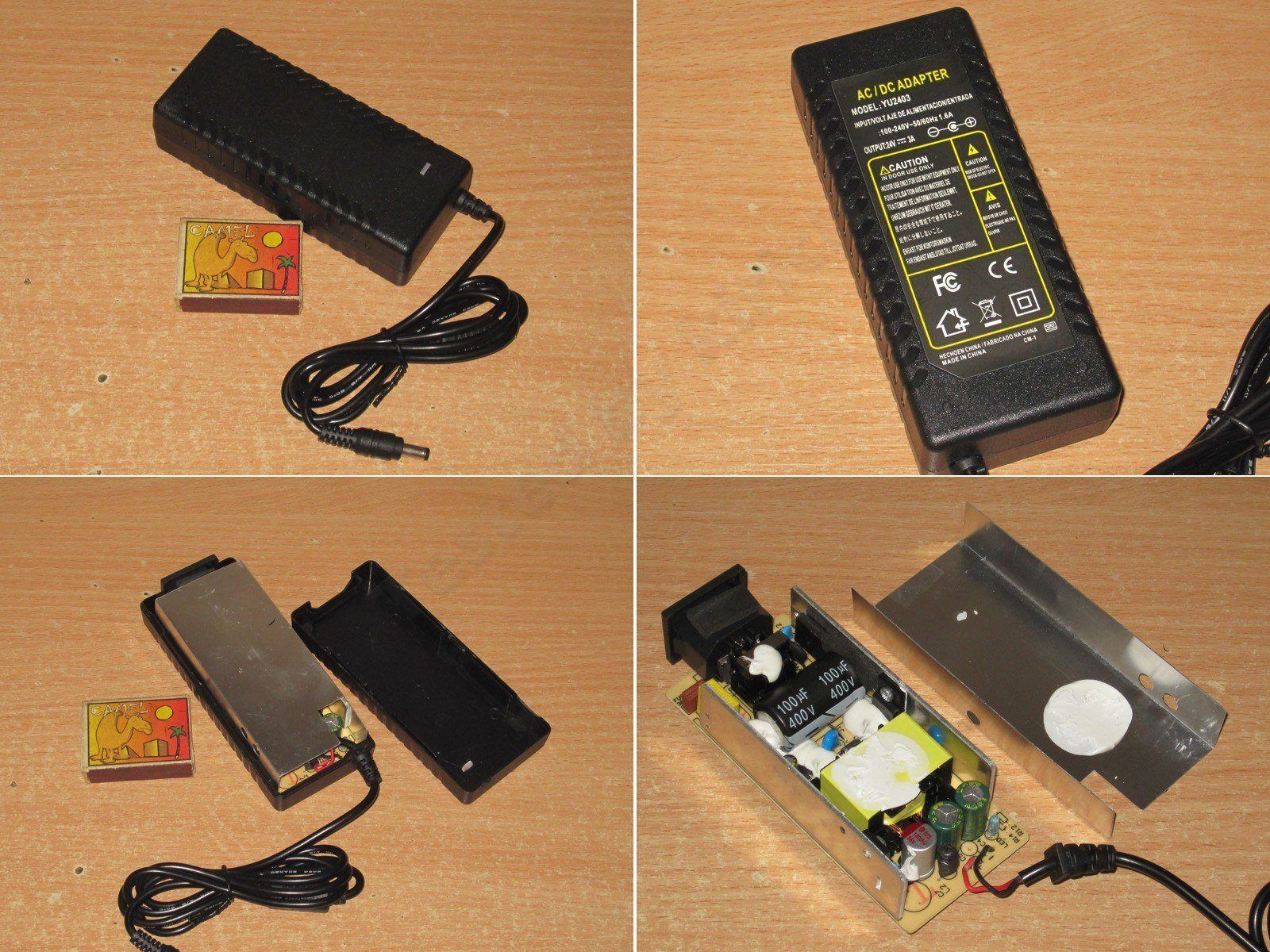
The layout is fairly compact, and the components are secured with sealant.
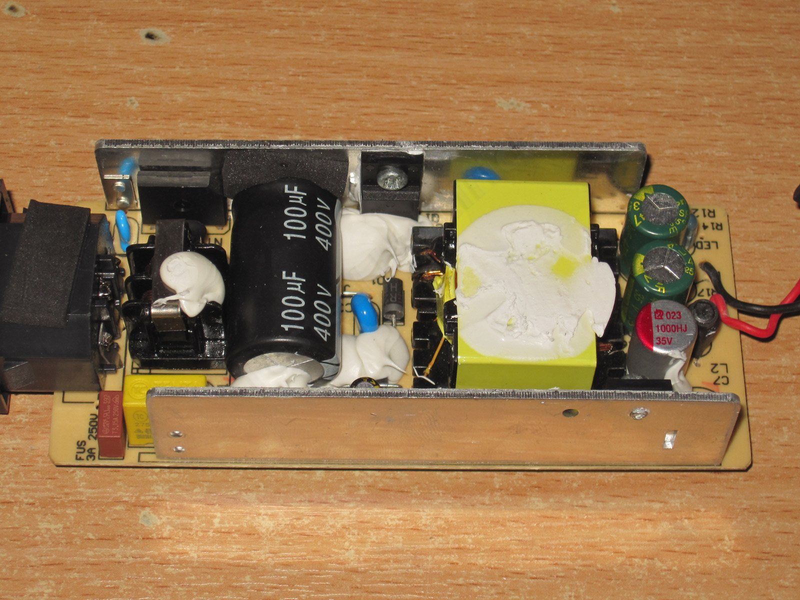
On the input side, there is a filter, a thermistor and a 100 µF capacitor. On the output side, there are three capacitors: one 1000 µF, 35 V polymer capacitor and two standard 470 µF, 35 V capacitors, along with a decent inductor.
As a bonus, they used a synchronous rectifier instead of a diode assembly. I should admit that some time ago I suggested they use chips like these, though that was for the 12 V models. Here, the factory decided to get ahead of the curve, just as it did with the polymer capacitor and inductor.
A Y capacitor is tucked between the transformer and the heatsink.
I have no complaints about electrical safety either. I’ll note that the PWM controller’s supply resistors and the discharge resistors are each made up of two resistors in series to improve reliability and safety. The solder points for the heatsink mounts have also been moved farther away from the live traces.
Of course, I still have a few minor comments, but it’s clear that the manufacturer looked at what we recommend for the 12 V models and simply carried those changes over to the 24 V version.
The actual input capacitance is 84 µF, which is still fine for a 72 W power supply. The output capacitance is 1800 µF, though I seem to have chosen the wrong test points, because for some reason the ESR reading came out quite high.
The protection current is set to around 3.7–3.6 A when cold and hot. It could be lowered a little more, but it is acceptable as is.
As expected, ripple is low: even at full power, the main ripple is around 15–20 mV, and no more than 45–50 mV even with the “spikes” included.
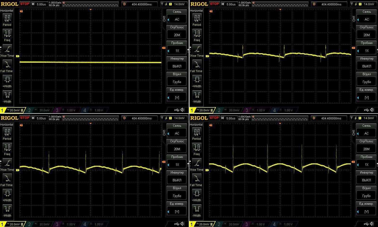
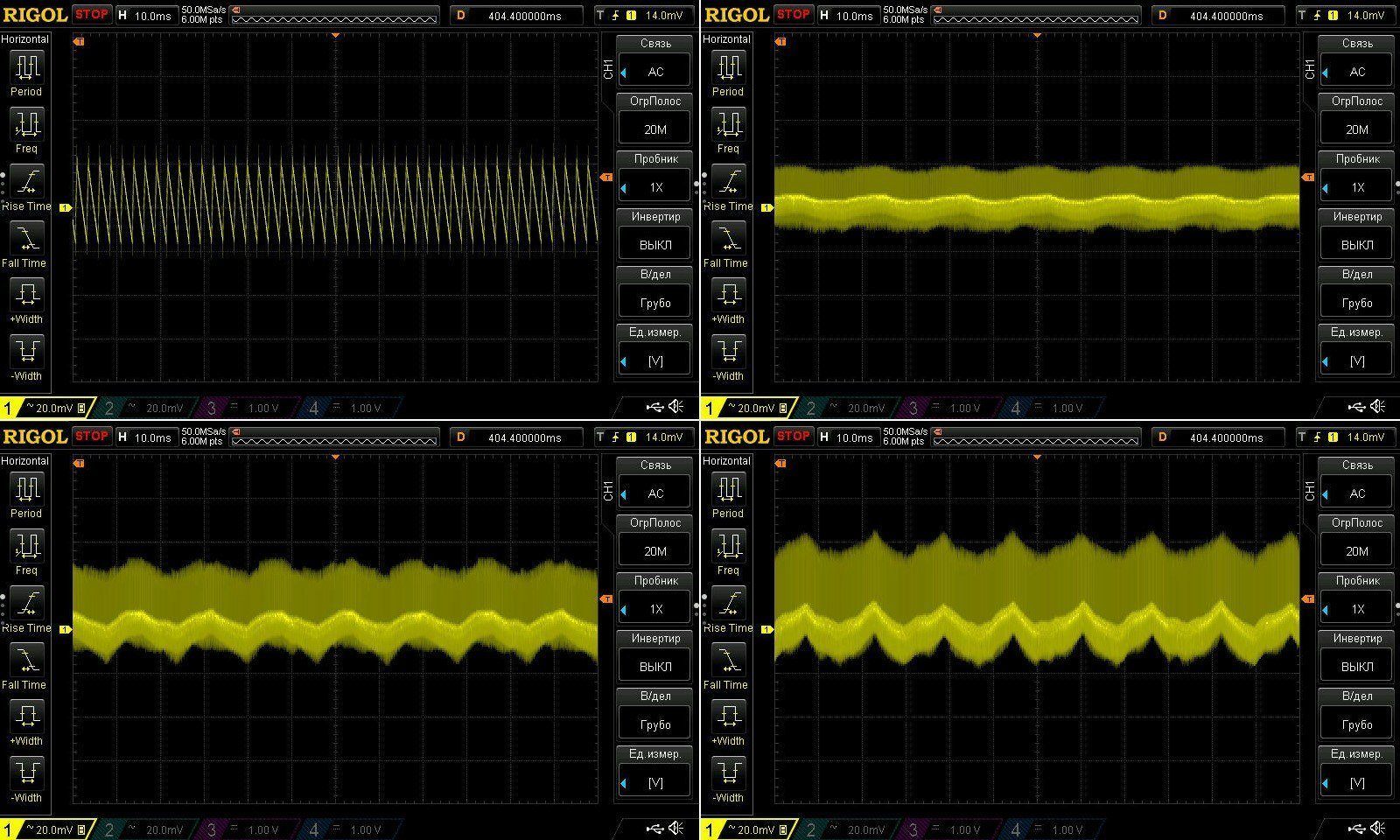
There is a little 100 Hz ripple at low frequencies, but looking at its actual magnitude, it is negligible.
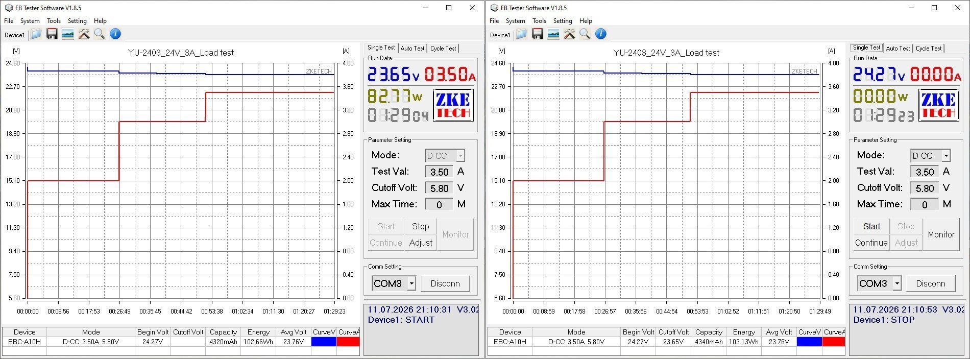
The load test was run at currents of 2, 3 and 3.5 A, i.e. close to the overload shutdown threshold.
There is no change in voltage as the unit warms up—or rather, it is smaller than the electronic load can measure.
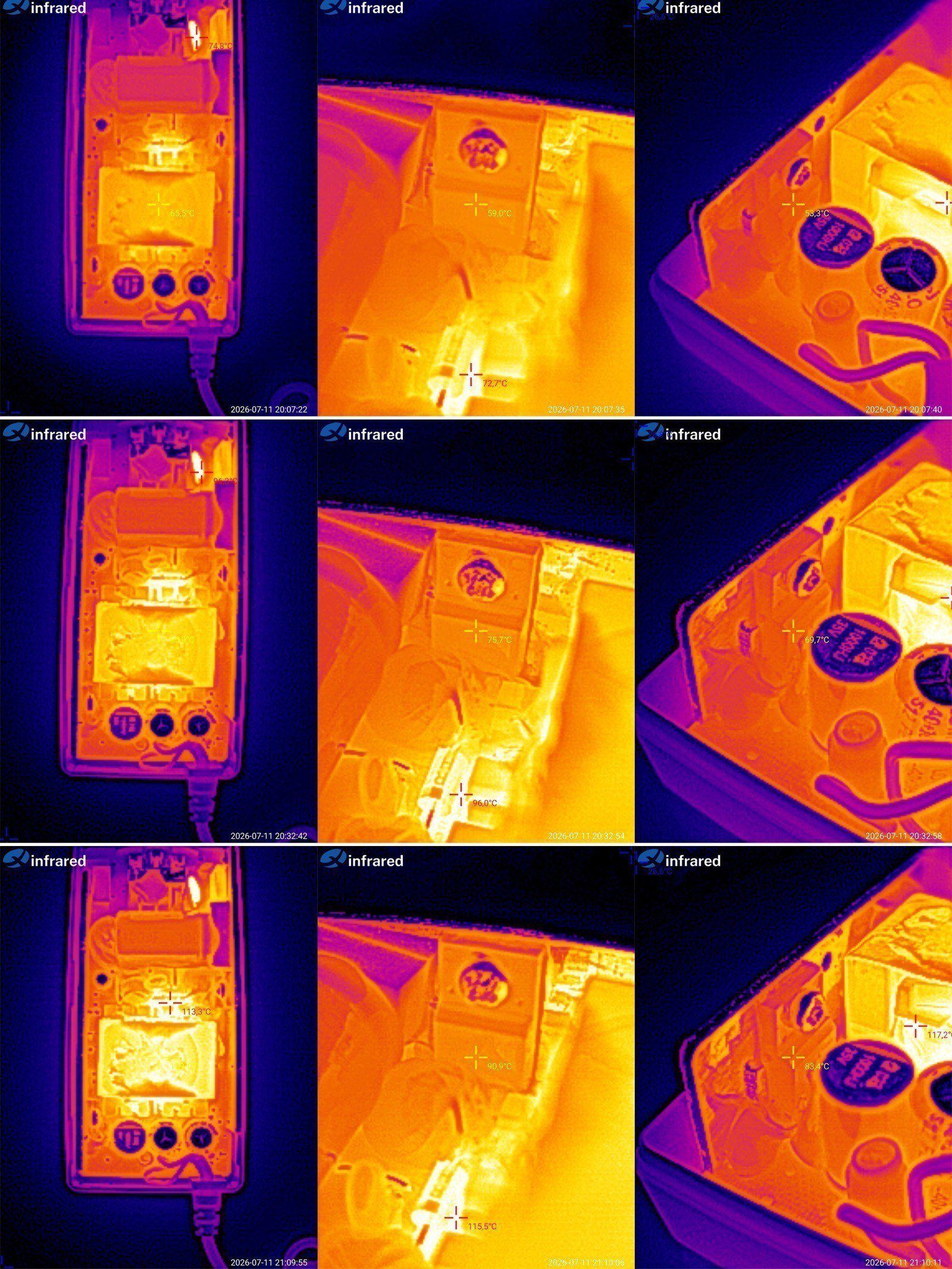
Now for the temperature rise.
At 2 A: transformer 65, transistor 59, rectifier 53 °C
At 3 A: transformer 87 °C, transistor 76, rectifier 70 °C.
At 3.5 A: transformer 109, transistor 91, rectifier 83 °C.
You could say the power supply handles its rated 3 A excellently. In fact, it could handle 3.5 A too, since the only component that started overheating was the transformer—and you may remember that I removed the metal plate that served as its heatsink.
I think this unit would also run at 3.5 A for extended periods in its original form, though I wouldn't recommend it. I'll probably suggest to the manufacturer that they lower the overcurrent protection threshold a little, to around 3.2–3.3 A. That would make overheating this power supply even less likely.
And now we've reached the tests of the 12 V power supplies. There are 10 of them here, but there's a catch: quite a few are essentially the same unit, just with different configurations.
I'll start with the little one: 12 V, 1 A. The case is, of course, an “adapter”; I don't think they make many desktop versions like this.
Right away, we're greeted by some impressive cost-cutting. It looks like they saved on everything. Let's see how it performs. By the way, I don't think I've come across this model—or the next one—in this exact form before, though I've seen very similar, better versions.
One major issue right off the bat: the interwinding capacitor is a standard type, rated for just 1 kV. So this power supply should only be used where people cannot come into contact with any live parts connected to its output. But really, it's easier to install a proper capacitor.
There's a 15 µF capacitor on the input and a 680 µF, 16 V capacitor on the output. The transformer is absolutely tiny.
The assembly is generally neat, but I have some concerns about the clearance between the primary and secondary sides: there's a narrow spot.
I should note, though, that this uses a dedicated chip with a built-in high-voltage transistor and, very conveniently, an external current-sense resistor.
I remember using a feature of the TOP24x controllers once: you could use a higher-power PWM controller and lower its protection threshold in software, getting slightly better efficiency.
Here, too, you can use a higher-power chip, dial back its protection, and get more reliable operation.
The actual input capacitance is 12 µF, and the output capacitance is 570 µF, but that's fine for a power supply rated at 12 W maximum.
The protection threshold is set to 1.5 A and is almost unaffected by temperature. In my opinion, it should be lowered; around 1.2–1.3 A would be more appropriate.
The high-frequency ripple is pretty dismal: the main component is 250–300 mV, and with the “spikes” included, it's 550–600 mV. You can improve things a little by adding a polymer capacitor to the output, without making any other more noticeable changes.
At 100 Hz, everything is more or less as expected: the overall swing is large, but the low-frequency ripple is well within spec.
The test was carried out in two stages, at 0.5 and 1 A. Note that the power supply's output voltage changes noticeably as it warms up; this is clear from both the graph and the readings. At the start, the no-load voltage was 11.92 V. After warming up, it rose to 12.01 V. But this is perfectly normal, especially since regulation is done on the primary side.
Temperature rise. It was awkward to get to the chip, so check the temperature of the transformer and output diode.
0.5 A — transformer 60, diode 76
1 A — transformer 87 degrees, diode 112.
Well, in principle, the diode does get a bit too hot. You can mitigate that somewhat simply by making its copper area larger. And if you replace the output capacitor with a polymer one, the result will be quite good for a budget unit.
The second 12 V power supply. This one is rated for 2 A; incidentally, its case looks very similar to those used for 24 V, 2 A power supplies.
The transformer is also not very large, but the internals are clearly more substantial. It has an input filter, two output capacitors, and an optocoupler.
Overall, everything is much better here. They even fitted a Y capacitor rather than an ordinary one, as in the 1 A version.
I have no concerns about electrical safety either. This power supply is based on a chip similar to the one in the previous model, so it most likely has overtemperature protection as well.
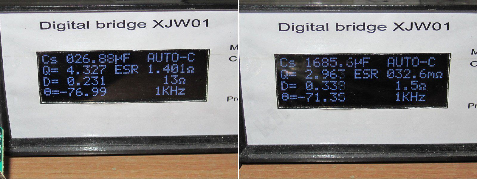
The input capacitor is 27 µF, and the output capacitors total 1700 µF. No complaints.
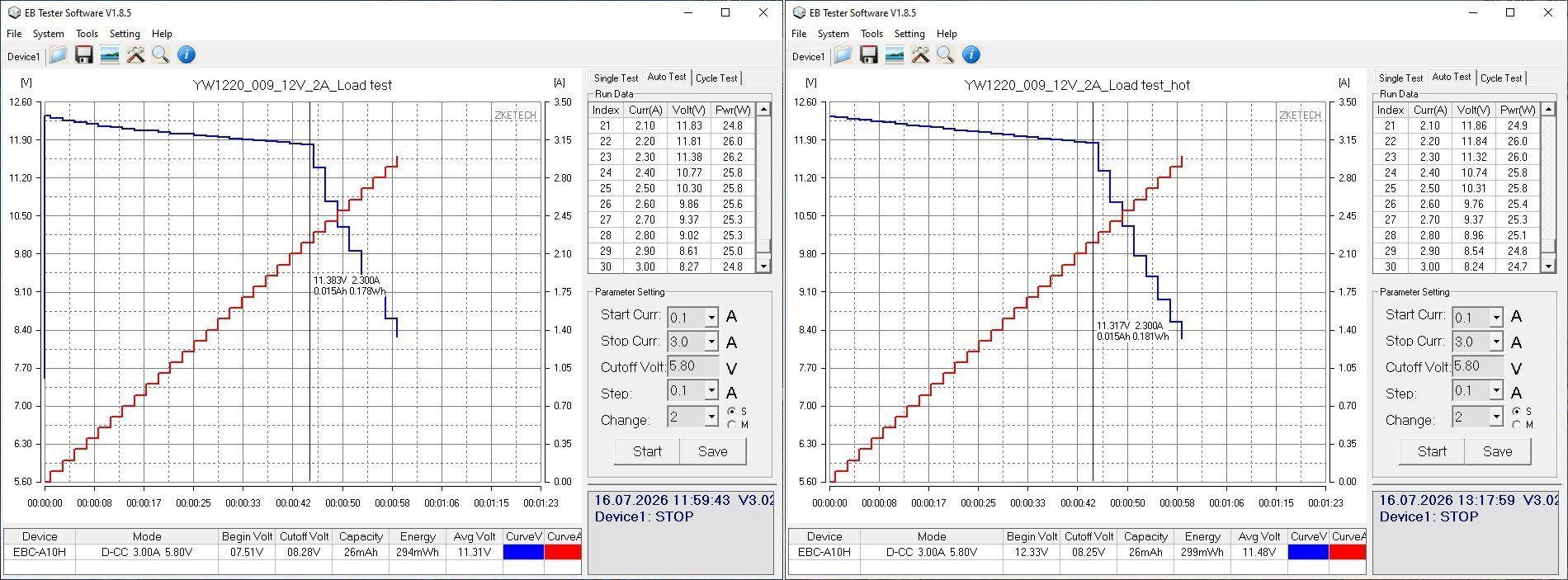
The protection current is set to about 2.3 A. The shutdown isn't abrupt, but fairly gradual; essentially, the power supply just lowers its output voltage. This isn't good or bad—it's simply one type of protection.
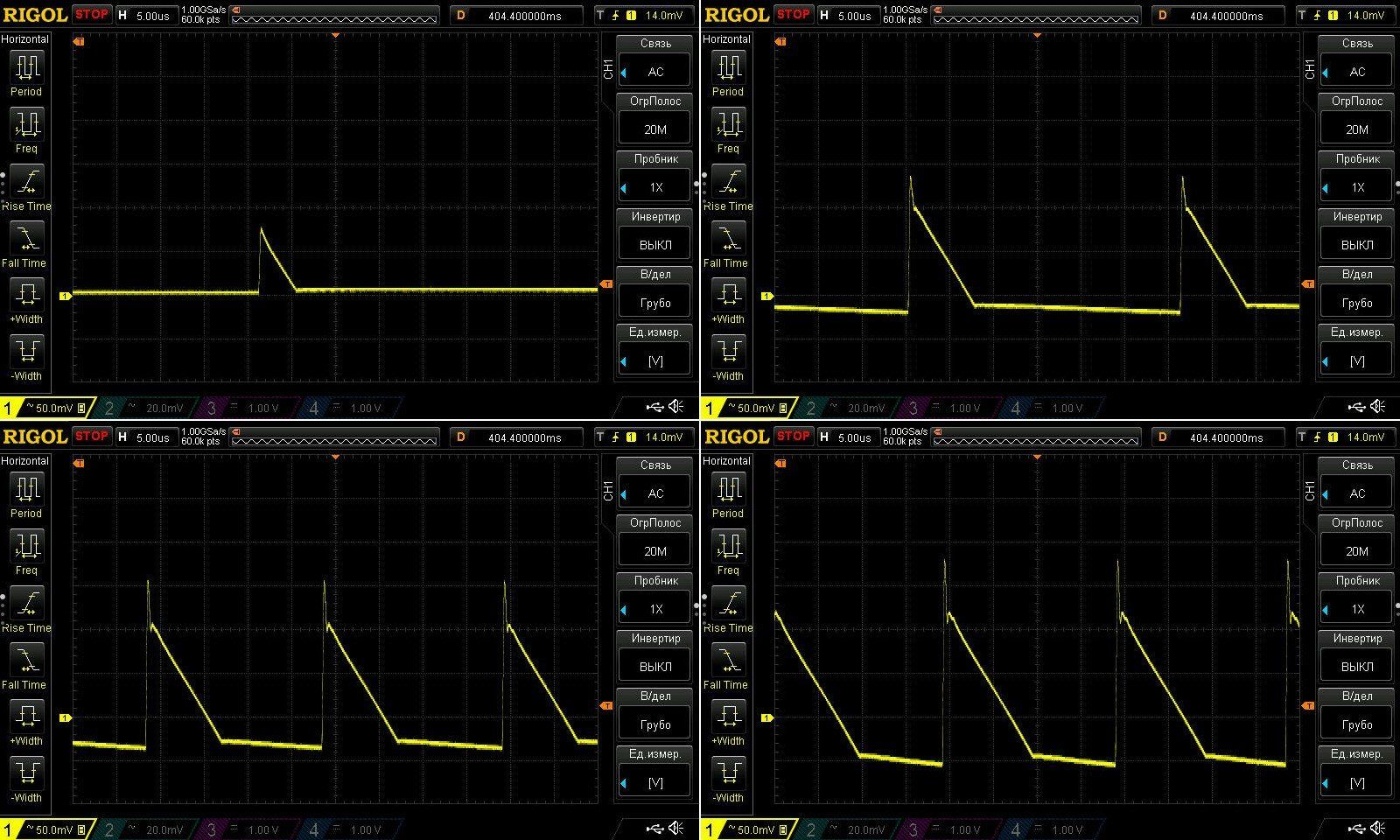
Ripple is better here: at maximum current, we get 170/230 mV. That's perfectly normal for a budget power supply, though of course lower is always better. One possible fix, again, is to replace one of the capacitors with a polymer one. I could have run an experiment, but I already have a pretty good idea of the result.
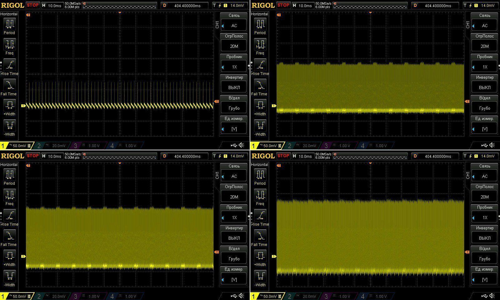
There is practically no ripple at 100 Hz.
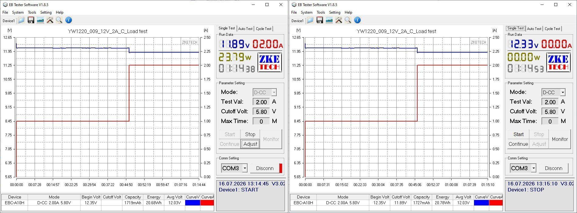
Testing was done at 1 A and 2 A, and I let it run for quite a while.
I have no complaints about voltage regulation, and the effect of heating is almost nonexistent—just about 20 mV.
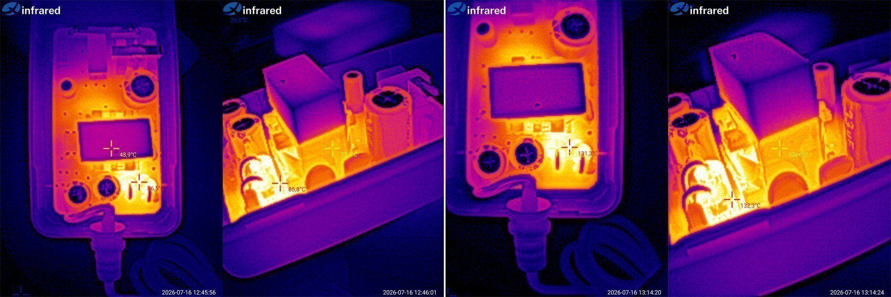
Let's check the temperatures.
1 A — transformer 73, diodes 86 degrees.
2 A — transformer 110, diodes 131 degrees.
Subjectively, the actual continuous current for this power supply is around 1.5 A. At 2 A, it clearly overheats, so either it needs modification or it should be sold as an honest 1.5 A unit.
At last, I've reached the models I've already had through my hands. I don't remember which iteration this is, but some work has clearly been done on this one.
The result is a number of standardized models that caught my eye in the first place, but ultimately needed some time and hands-on work from me.
A 12 V, 3 A model in the “adapter” form factor. This is exactly how it first came to me.
There's an input filter, components with plenty of headroom, and a large transformer.
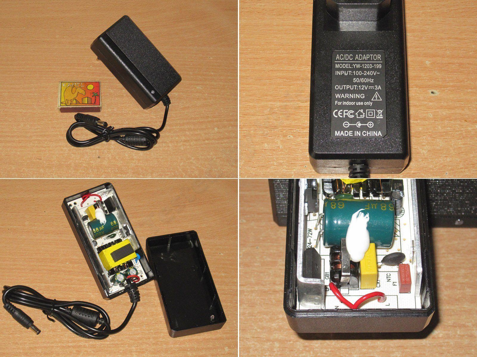
It looks fairly basic on the outside, but I liked that it worked quite well.
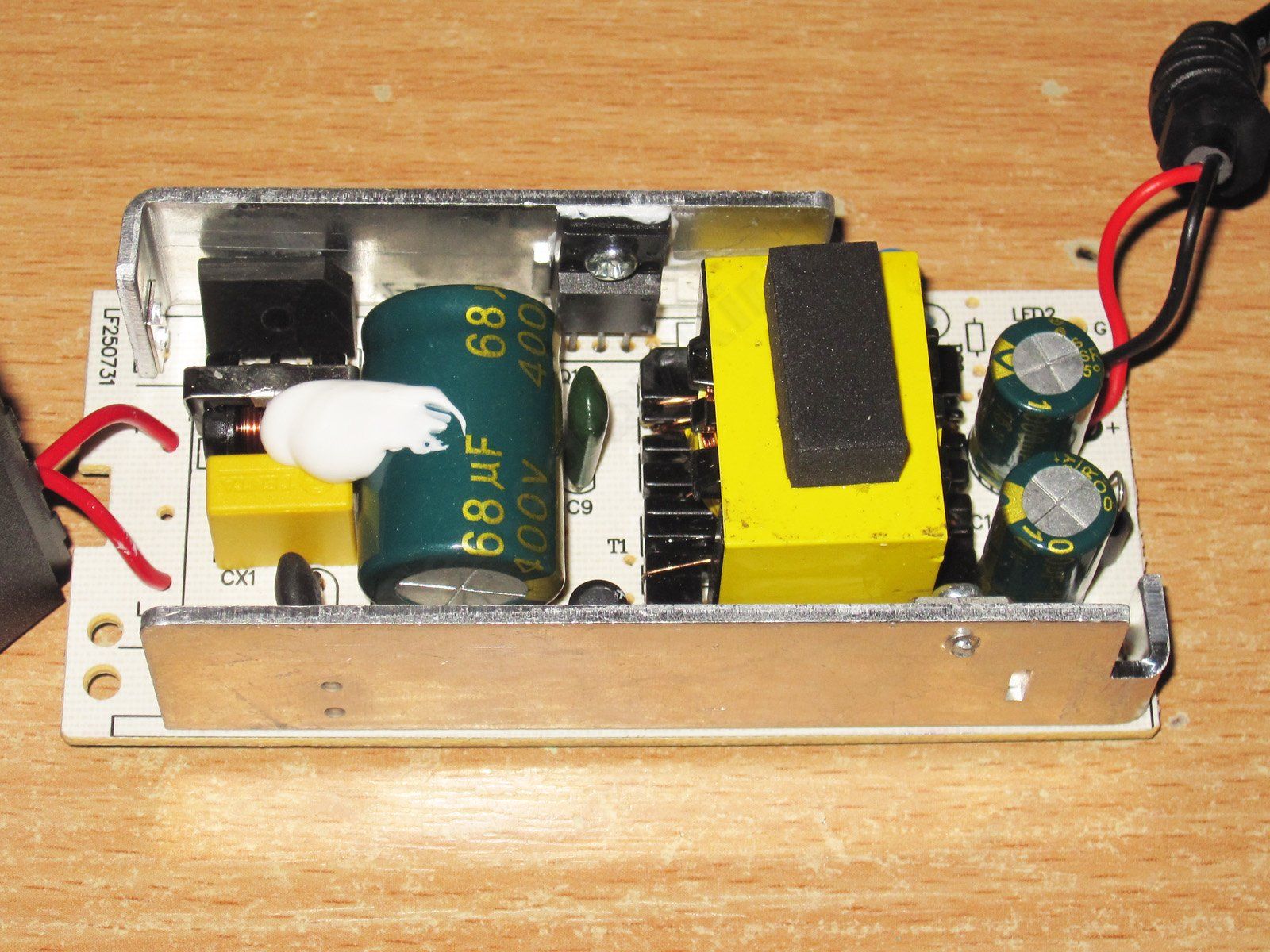
The transistor marking is almost unreadable. I should look for earlier versions; maybe it's legible on those. The output has a pair of 1000 µF capacitors.
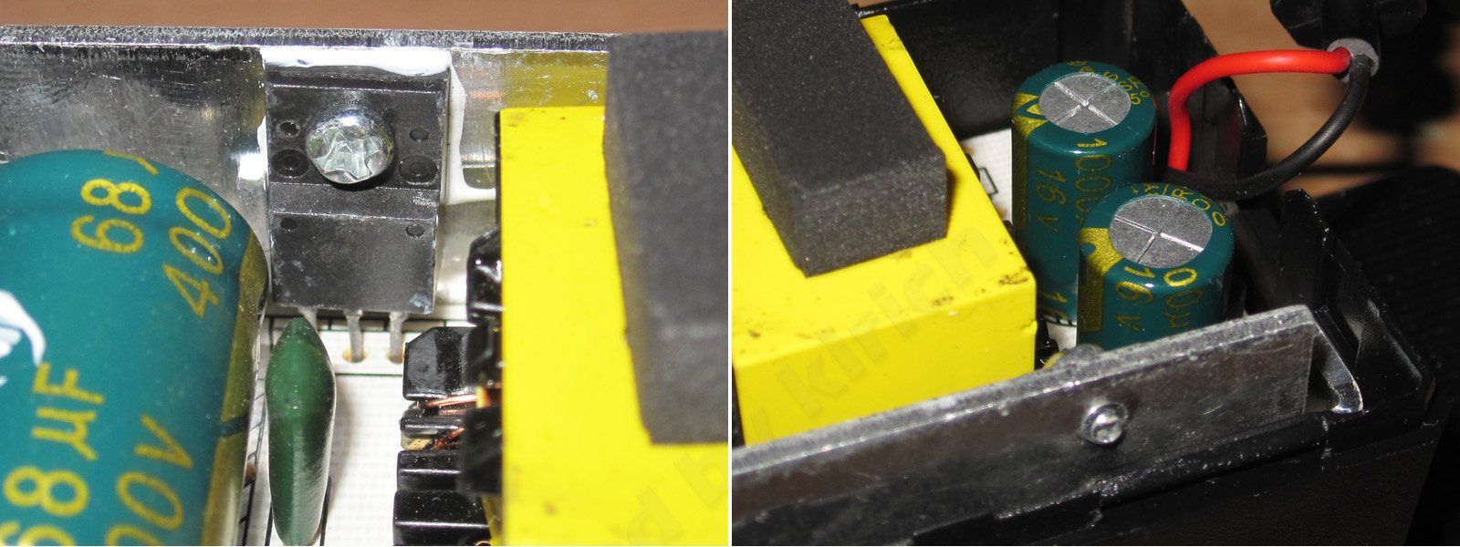
For safety, I'd give it more like 4 points. There are some weak spots, but overall it's reasonably tidy. And, incidentally, the PWM controller's supply resistor is made up of two resistors here as well, which is the right way to do it.
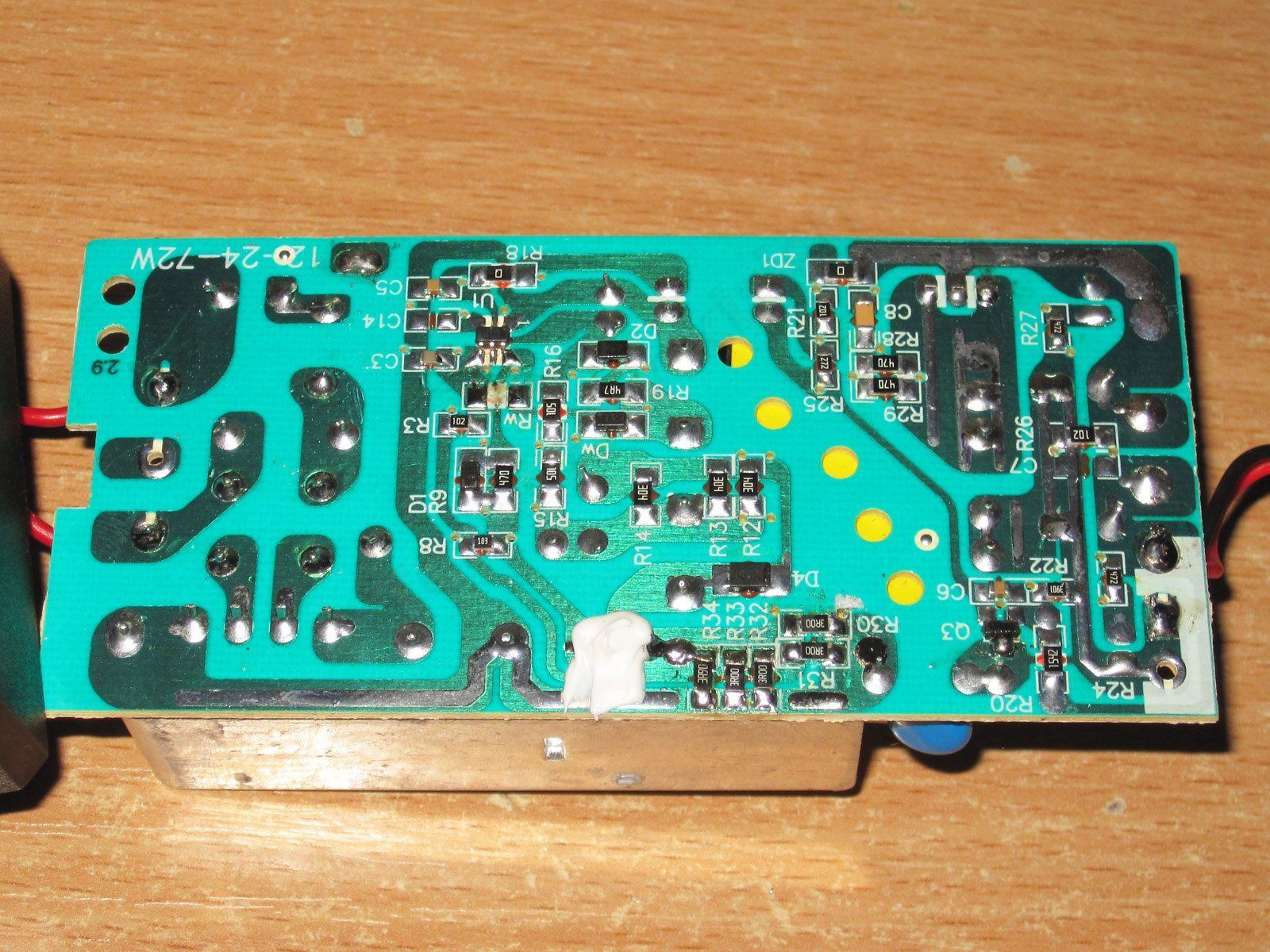
The input capacitance is 58 µF, and the output capacitance is 1560 µF in reality. That's quite reasonable for a 36 W model, and it should work at both 230 V and 115 V.
The protection current here is set in line with our recommendations and the positioning of the specific models.
Here, the protection current is set to 3.4 A, i.e. basic 3 A plus a little headroom.
High-frequency ripple at maximum current has a peak-to-peak amplitude of about 130–140 mV, which is roughly 1% of the output voltage and is normal.
A reminder: ripple was measured directly at the board output in every case; it will be lower after the cable.
There is some ripple at 100 Hz, but I’d say it’s acceptable.
The test was carried out in three stages, at currents of 1.5, 3, and 3.2 A, with the 3.2 A stage being the longest.
The voltage does depend on the load, of course, but that’s voltage drop across the cable. The effect of warming up is practically nonexistent, so I think we can safely ignore those 10 mV :)
And most importantly, the temperature.
At 1.5 A: transformer 51, transistor 49, and output diode assembly 55 degrees.
At 3 A: transformer 69, transistor 66, diode assembly 81 degrees.
At 3.2 A: transformer 80, transistor 77, diode assembly 88 degrees.
As you can see, nothing is overheating. All the main components are operating with a noticeable margin, so we’ve achieved our goal for now.
The next model has the same specs, 12 V, 3 A, but in a desktop form factor. This was Vitaly’s idea; we work together to push the Chinese manufacturers. Since it doesn’t really make much difference in this case, I had no objections.
This unit doesn’t even have a label; they just wrote on it with a marker and sent it for approval.
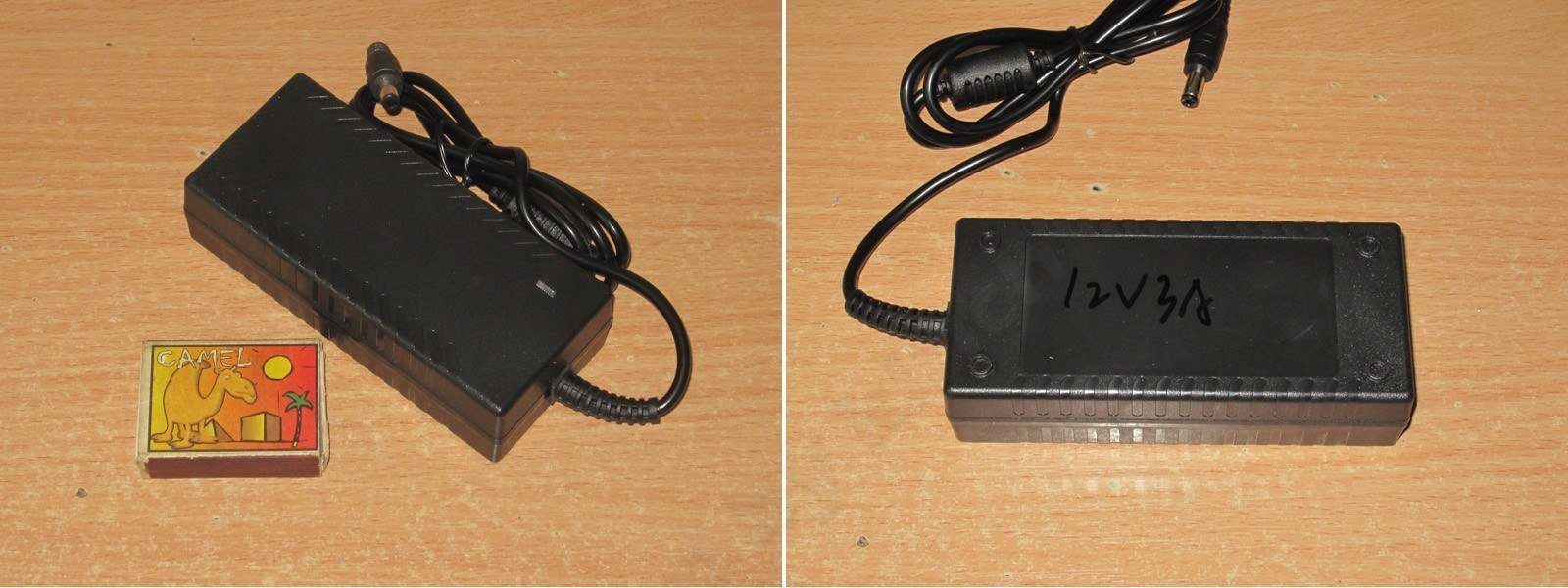
As you can see, it’s essentially exactly the same power supply as the previous one, but in a different enclosure. This model is perfectly viable as a product: not everyone wants a power supply in adapter form, just as not everyone wants a desktop version.
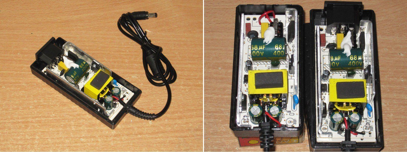
There’s no point inspecting anything or measuring the capacitors, so let’s go straight to testing the protection current.
We get the same 3.4–3.5 A, just as we wanted.
The ripple is about the same, which was also expected.
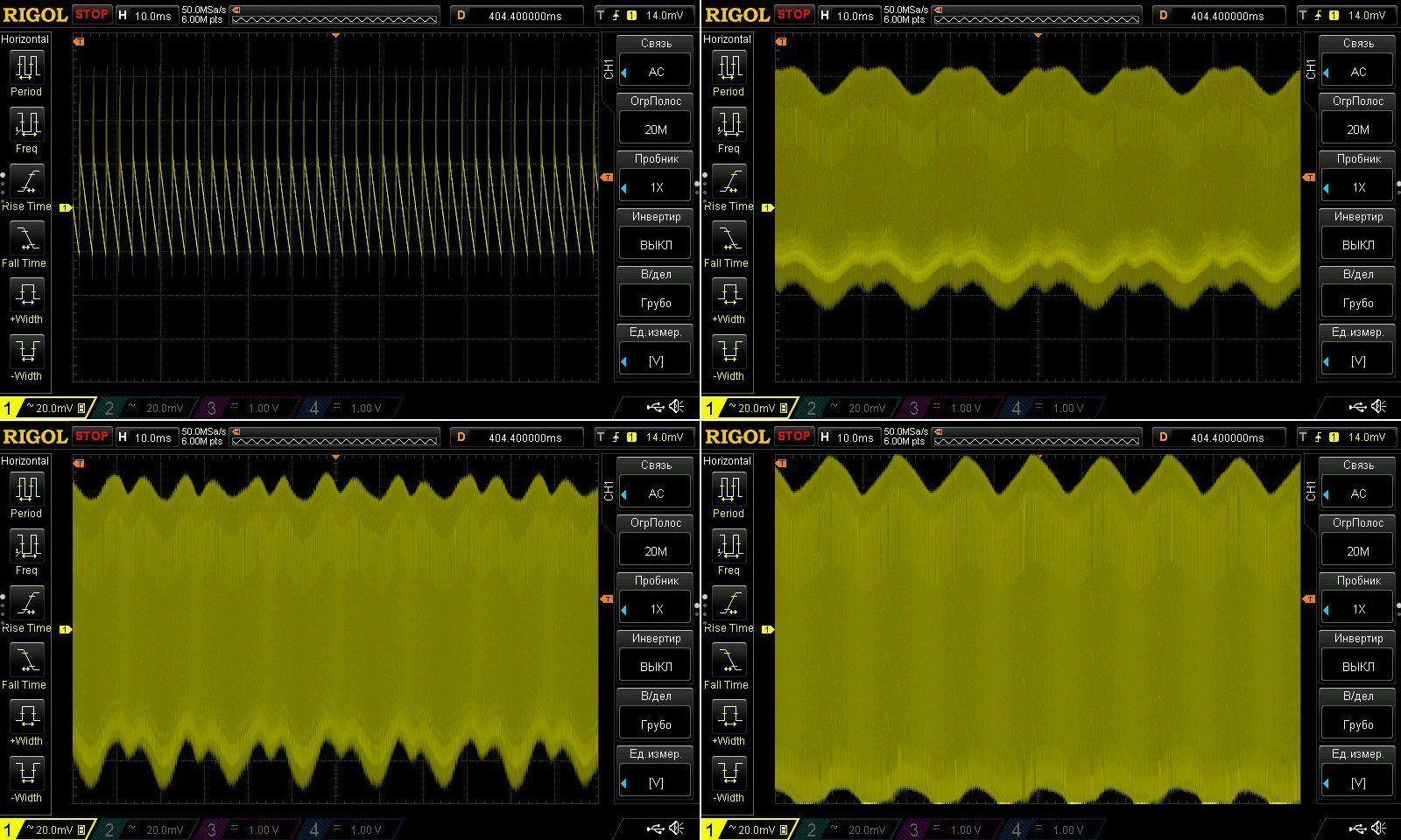
The warm-up test was run in almost the same conditions and at the same currents: 1.5, 3, and 3.5 A.
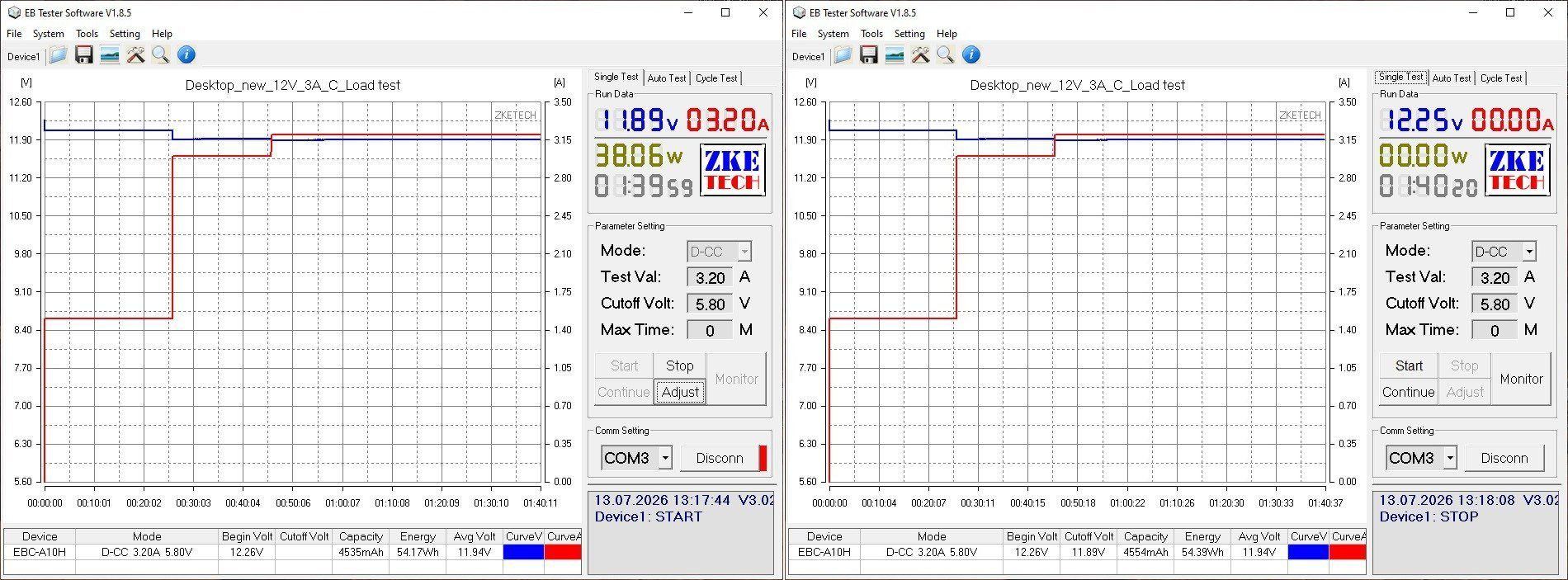
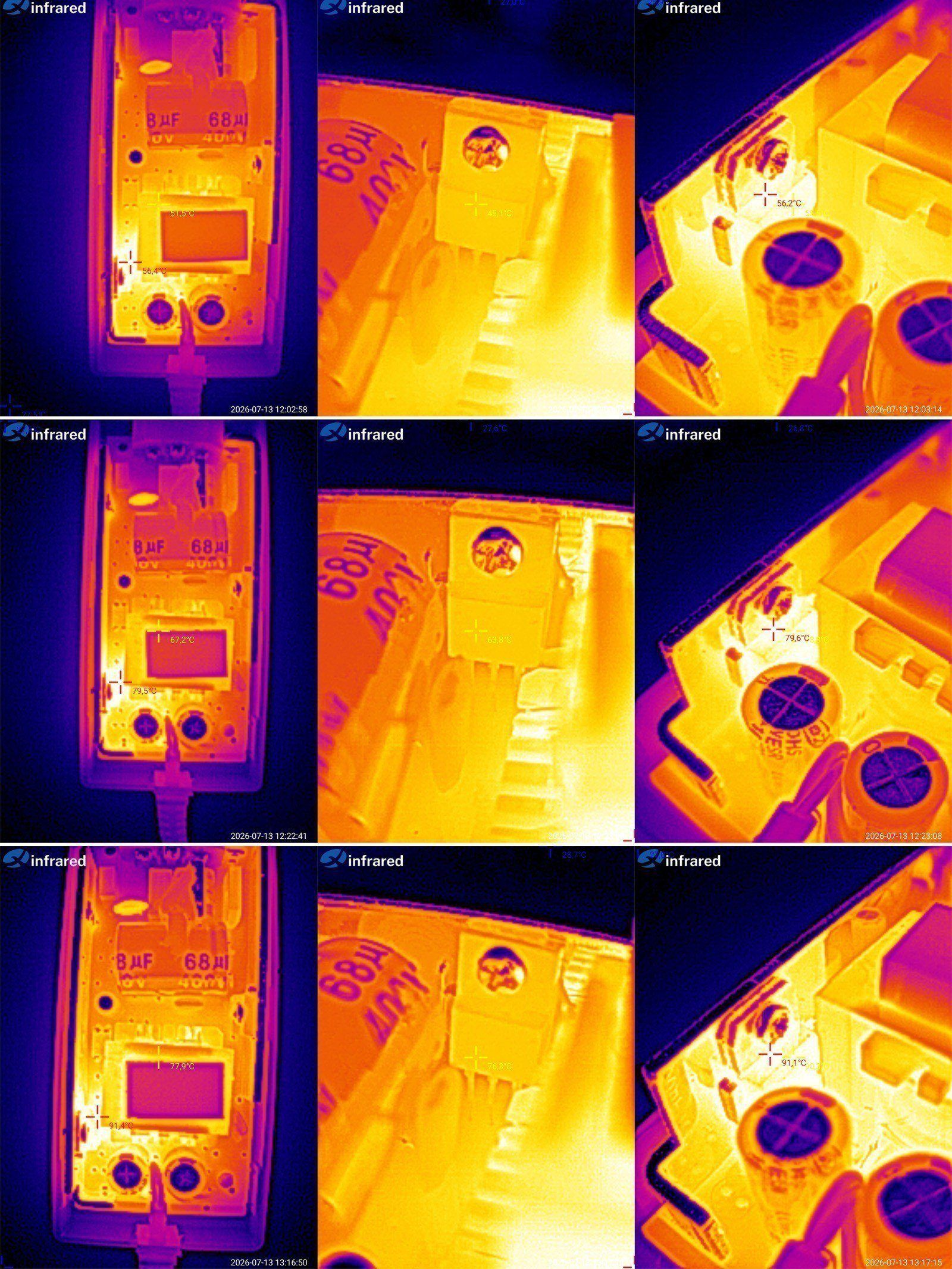
Temperature measurements for the main components.
At 1.5 A: transformer 52 degrees, transistor 48, diode assembly 56 degrees.
At 3 A: transformer 67 degrees, transistor 64, diode assembly 80
At 3.2 A: transformer 78, transistor 76, and diode assembly 91.
In the end, the temperatures are more or less the same: some components are a little hotter, others a little cooler. In any case, everything is within the normal range.
The next model is based on the same platform, if you can call it that, but is rated for 12 V, 4 A, or 48 W.
Adapter form factor, but with a few improvements.
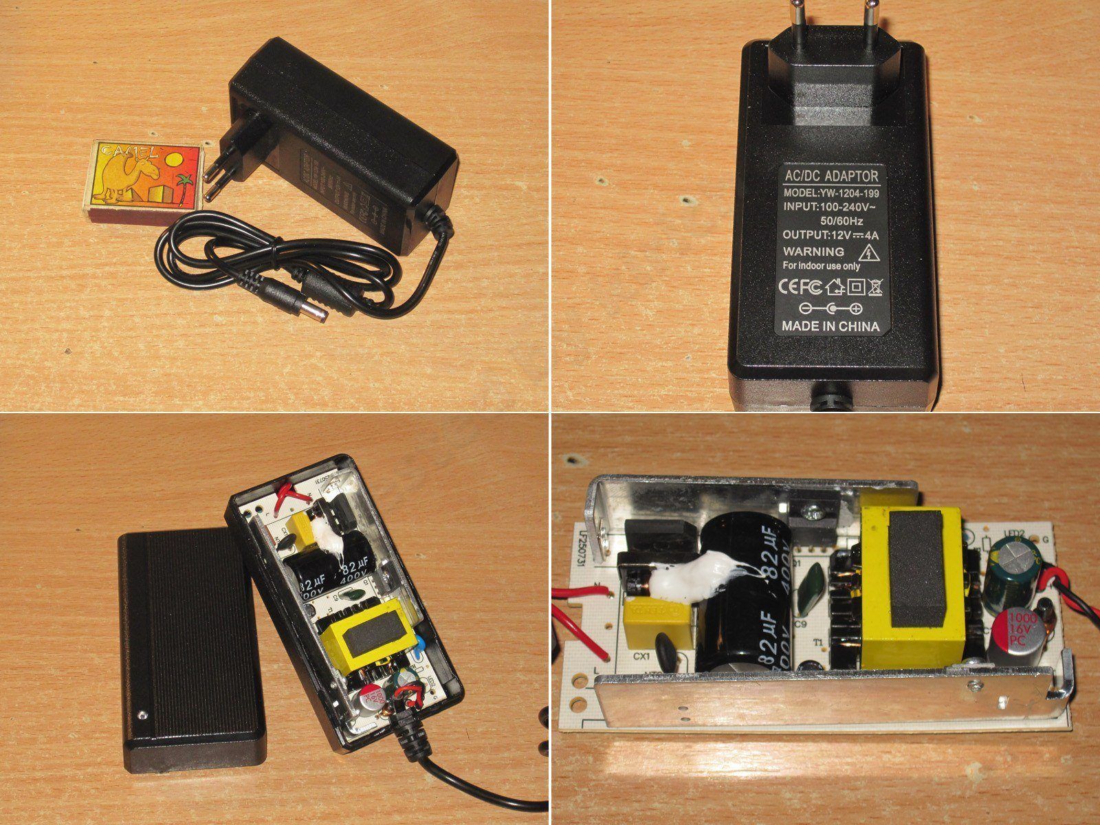
The input filter was retained. I can’t remember about the transistor now, but I think they asked for a more powerful one, though I could be wrong. The input capacitor, however, has a higher capacitance.
One of the output capacitors has also been replaced with a polymer capacitor, and the output inductor is rated for a higher current. The one fitted originally got noticeably warm at 4 A.
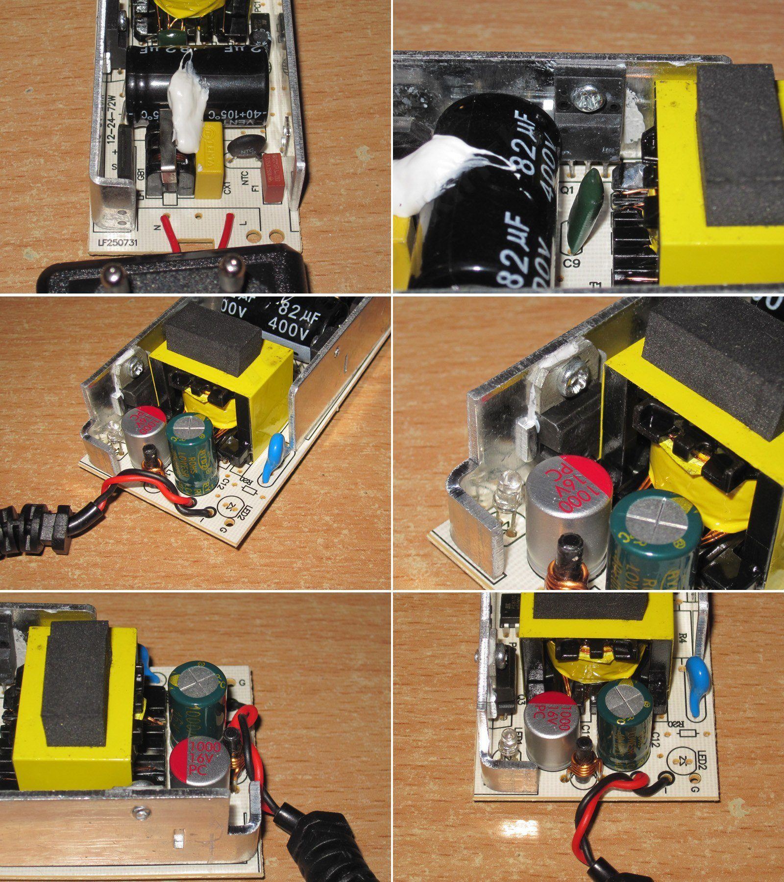
It’s the same board, but the shunt values have been adjusted for the different output current. The factory team handled the adjustments and sent videos of the tests along the way.
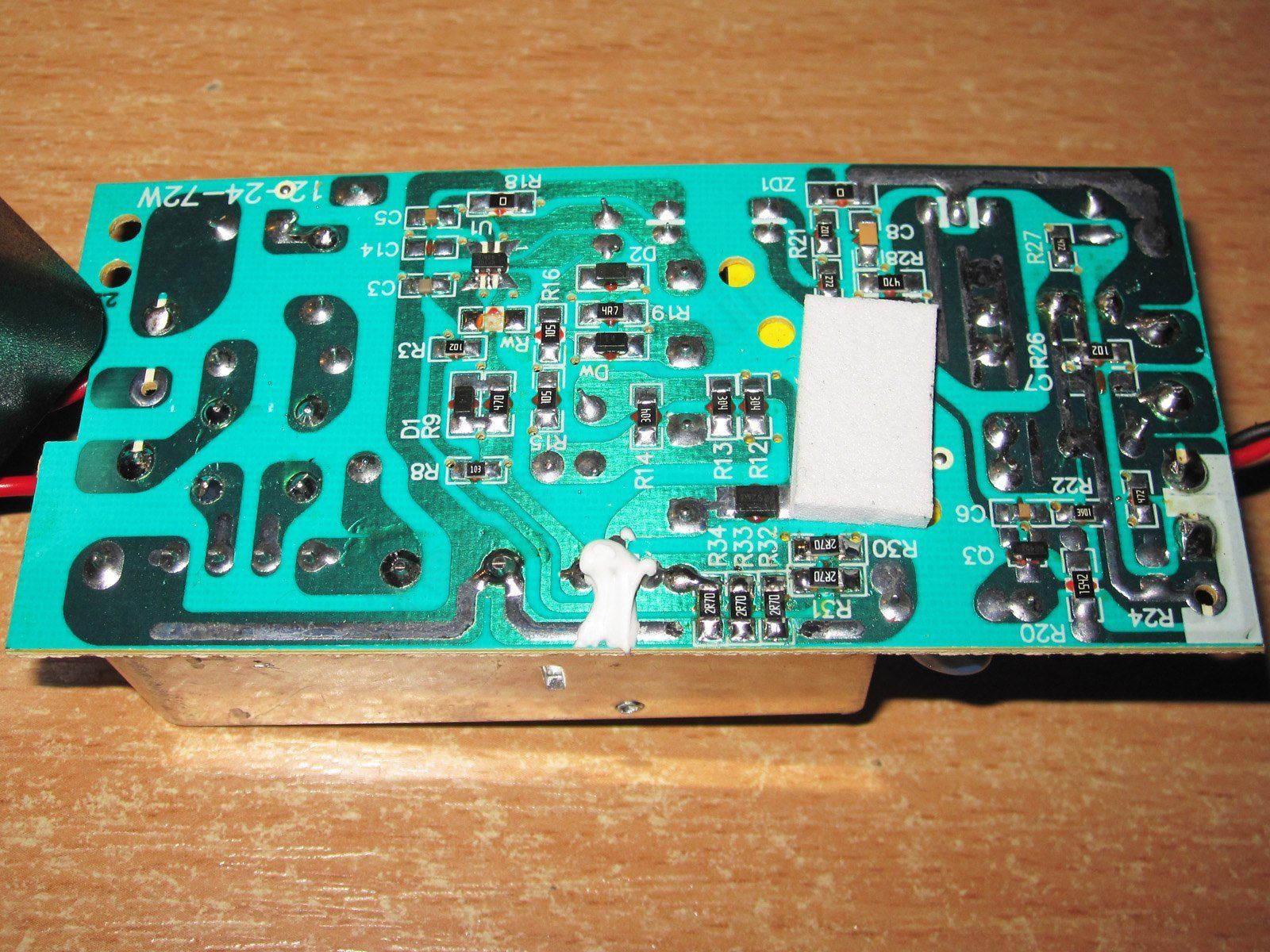
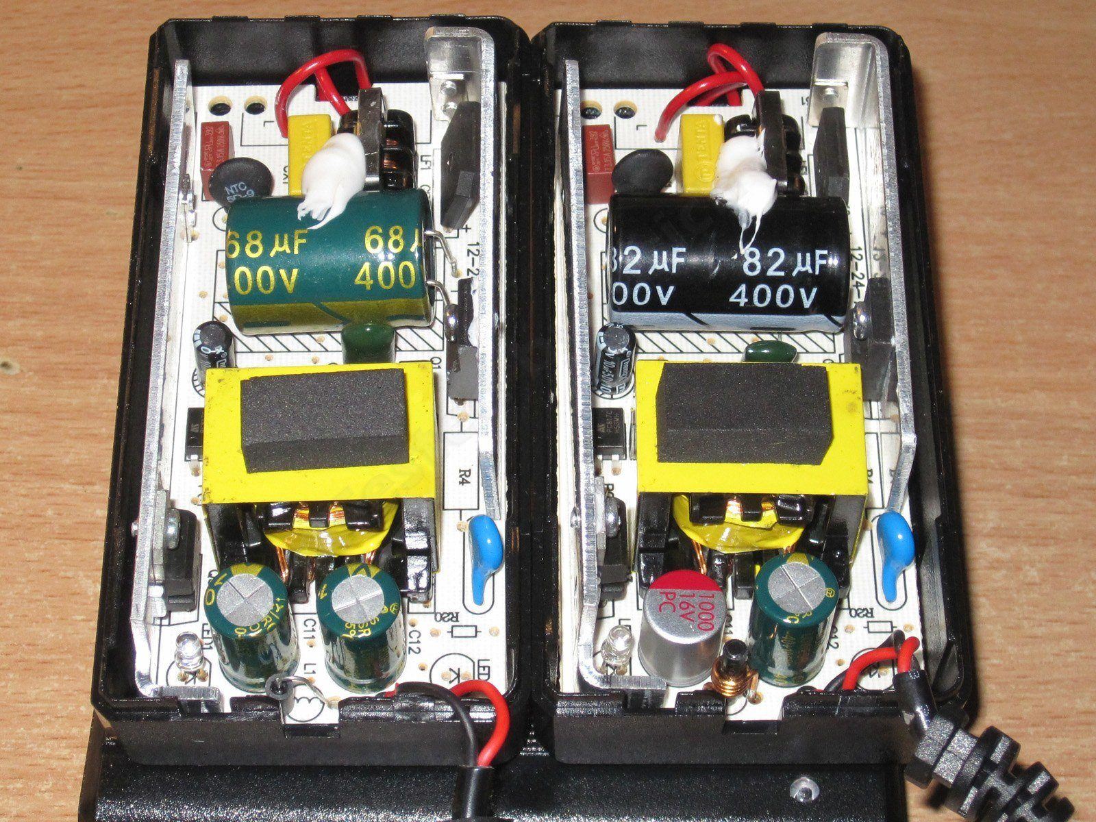
The 3 A model is on the left, the 4 A model on the right. You can see that the basic design is the same; only a few components have been changed.
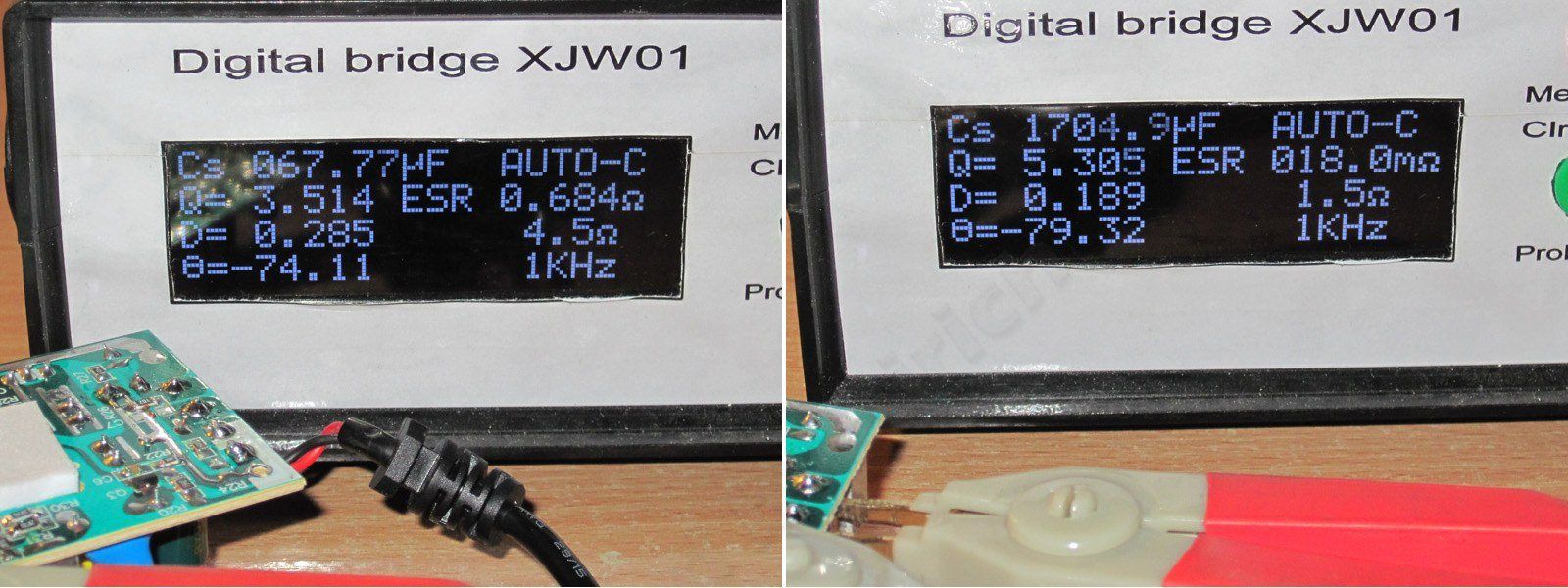
The input capacitor measures 67 µF, and the output capacitors total 1800 µF. Here, too, we got what we wanted.
The protection current came out to about 4.5 A when cold and 4.3 A when hot, i.e. close to the stated maximum.
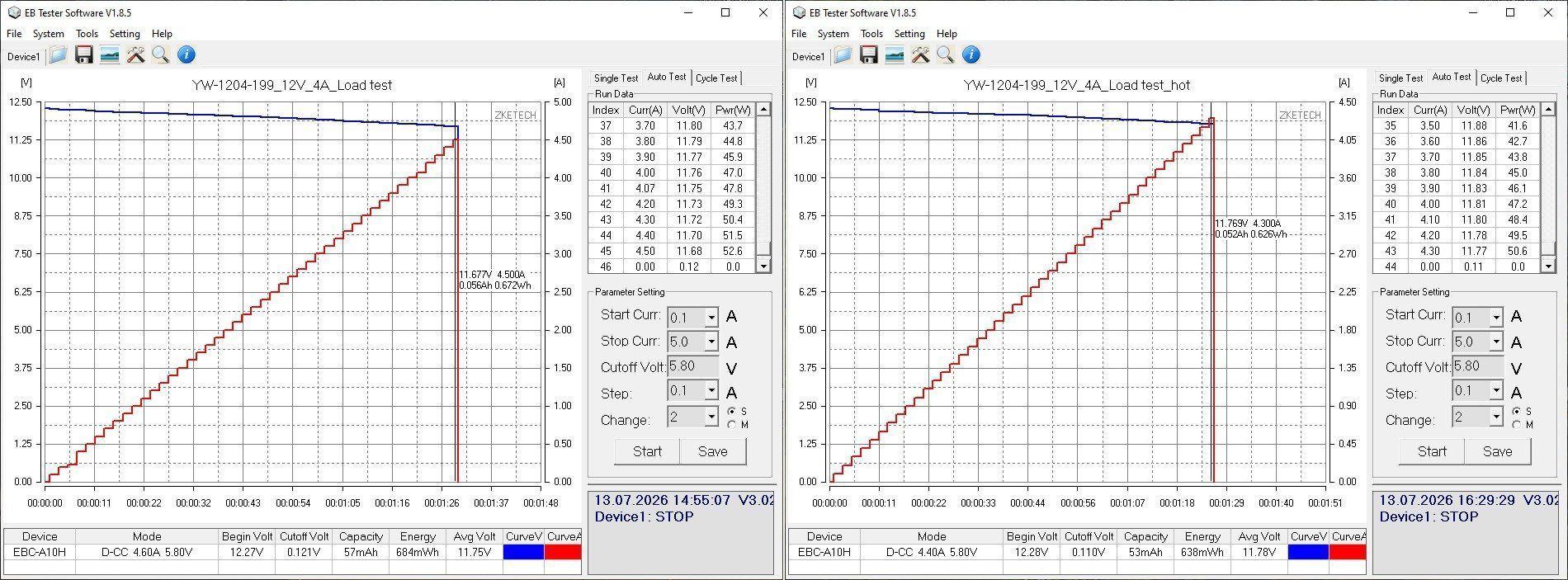
As I mentioned, the output stage was modified, which gave us noticeably less ripple at the output. Even at maximum current, we get 35 mV of main ripple and 60 mV including the "spikes"—pretty good, in my opinion.
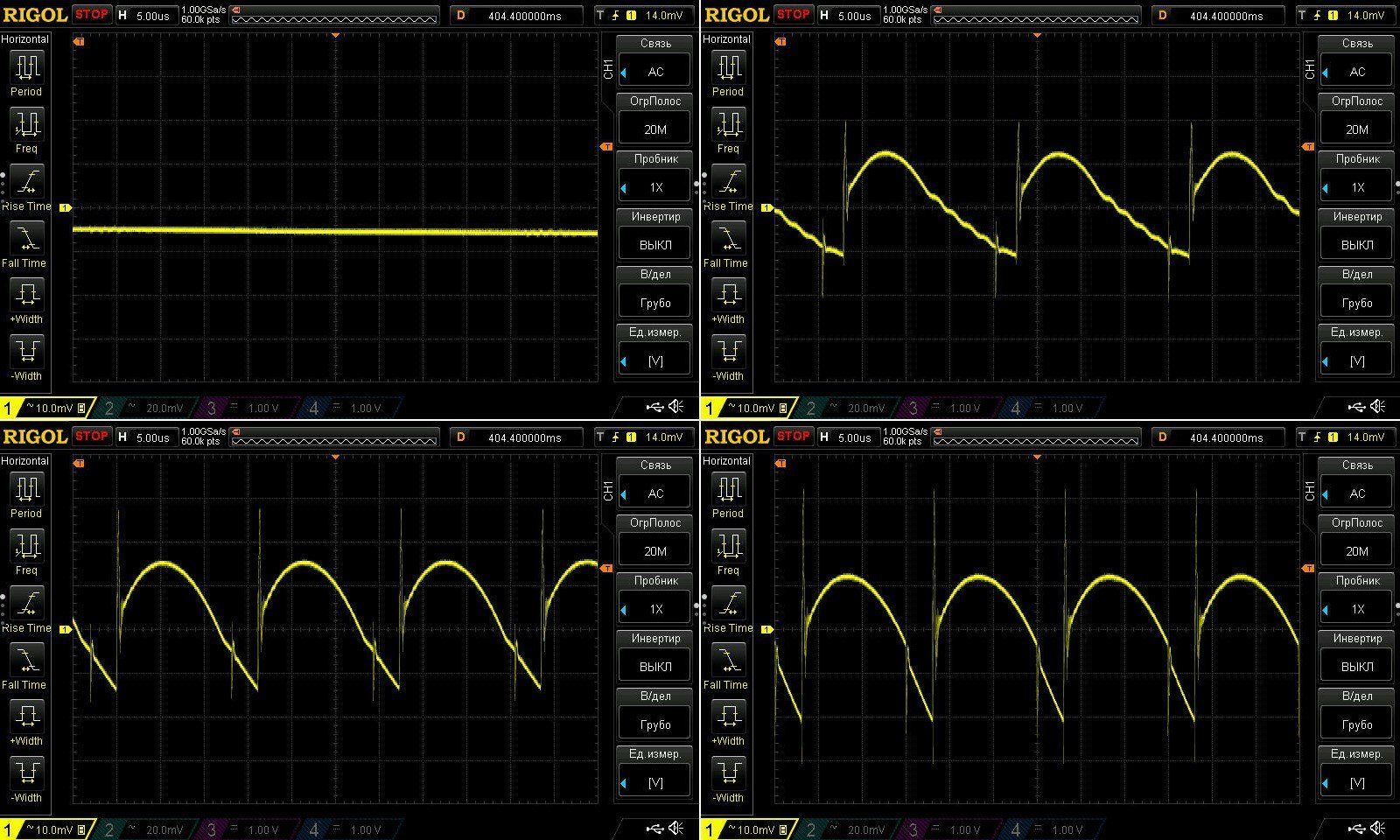
At 100 Hz, the waveform looks pretty scary, but it’s not actually that bad. The high-frequency ripple is simply small, so the 100 Hz ripple stands out more against it, especially with the oscilloscope set to 10 mV per division.
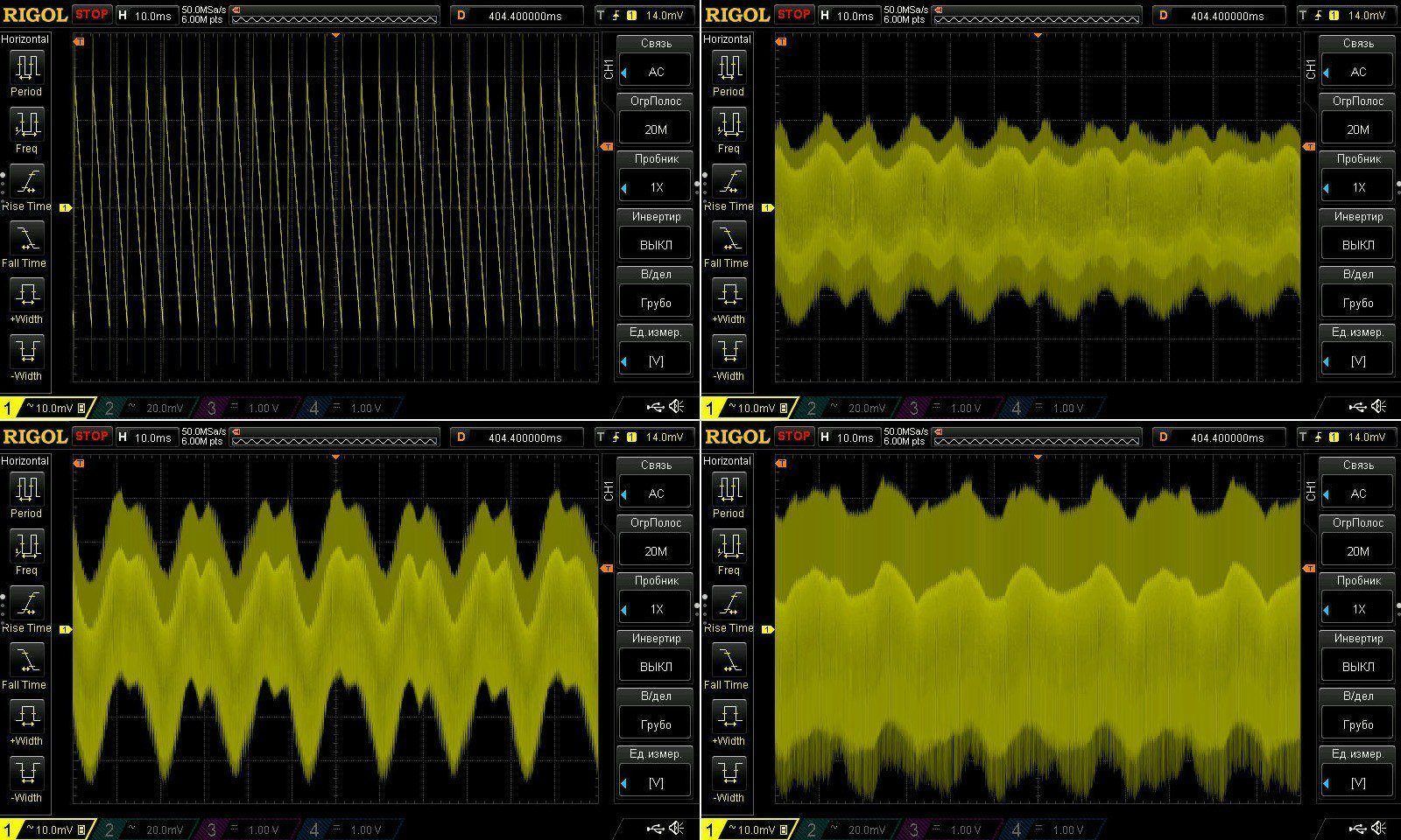
This test ran at 2, 4, and 4.3 A, but unfortunately it was briefly interrupted during the final stage, which caused the load to switch off. I resumed the test right away, but sadly there’s no continuous graph.
Now for the temperatures.
2 A — transformer 55 degrees, transistor 54, diode assembly 68
4 A — transformer 82 degrees, transistor 82, diode assembly 97 degrees.
4.3 A — transformer 90, transistor 90, and diode assembly 103 degrees.
All temperatures are within the normal range, but yes, there isn’t much headroom for higher ambient temperatures. I think it should handle somewhere around 15–20 degrees above normal room temperature.
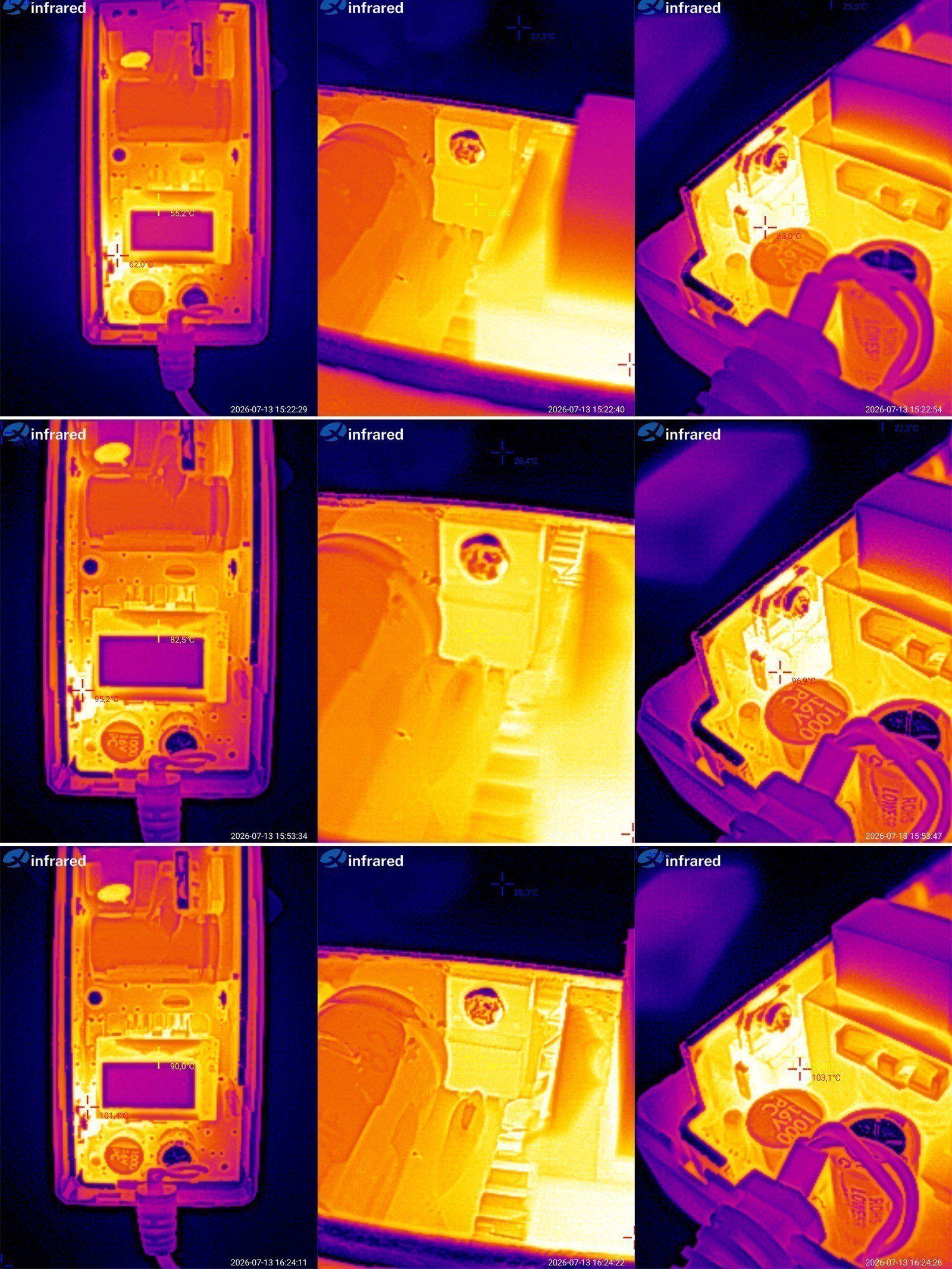
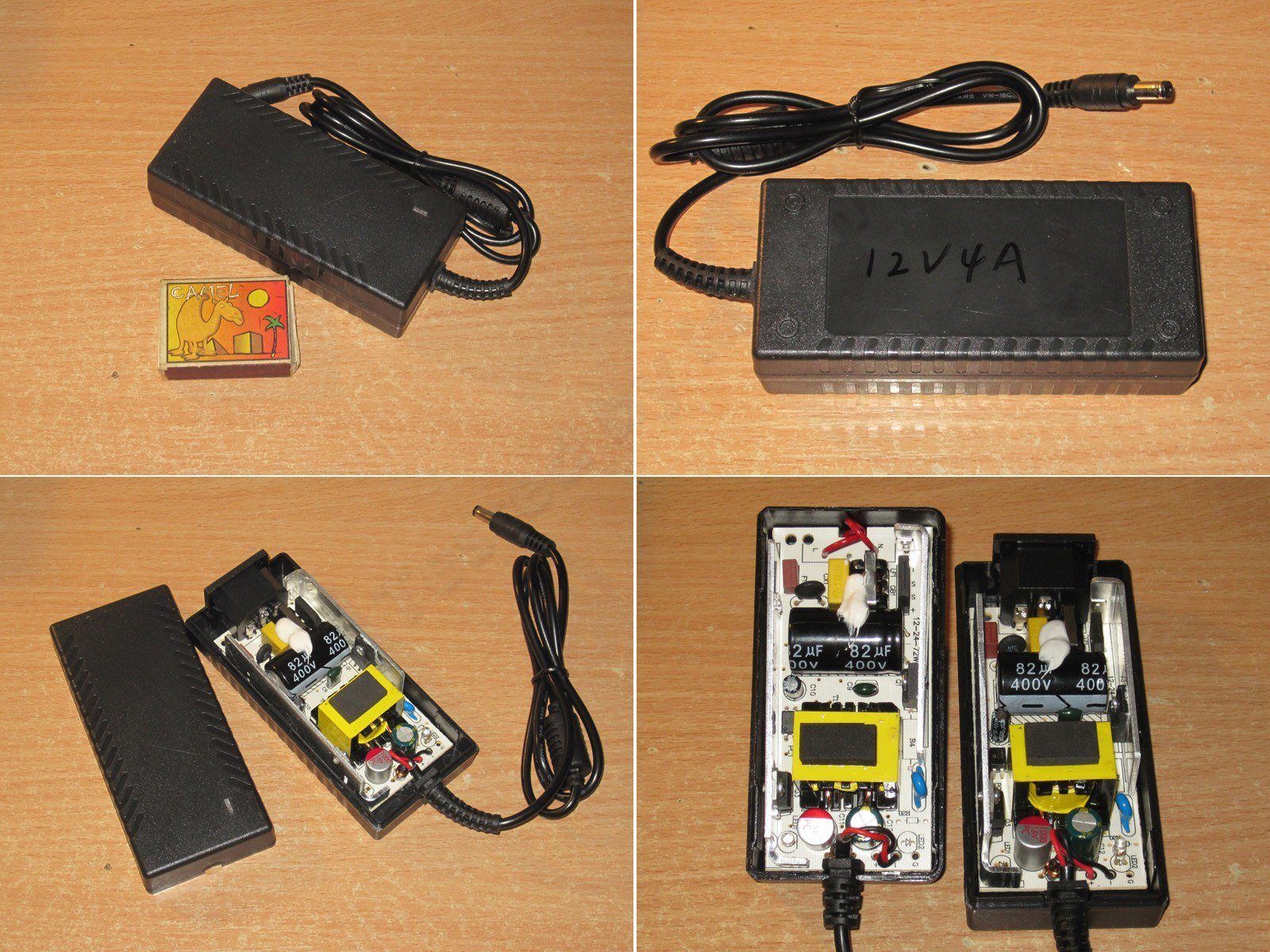
This is the same power supply, but in a desktop enclosure. Yes, the only difference is the type of enclosure.
The protection current ended up a little lower here. On the other hand, nobody expected this parameter to be precise; the main thing was for it to be slightly higher than the rated output current.
As I’ve already explained, too much current is bad, because then nothing stops the user from loading the power supply "to the max" and ending up with a lump of charcoal.
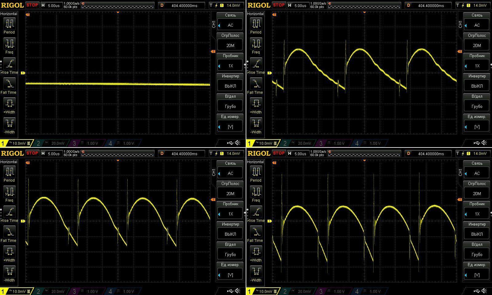
The ripple is much the same, since the boards are identical.
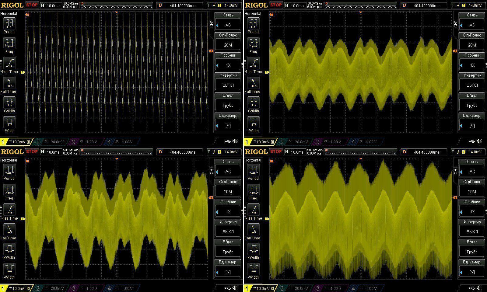
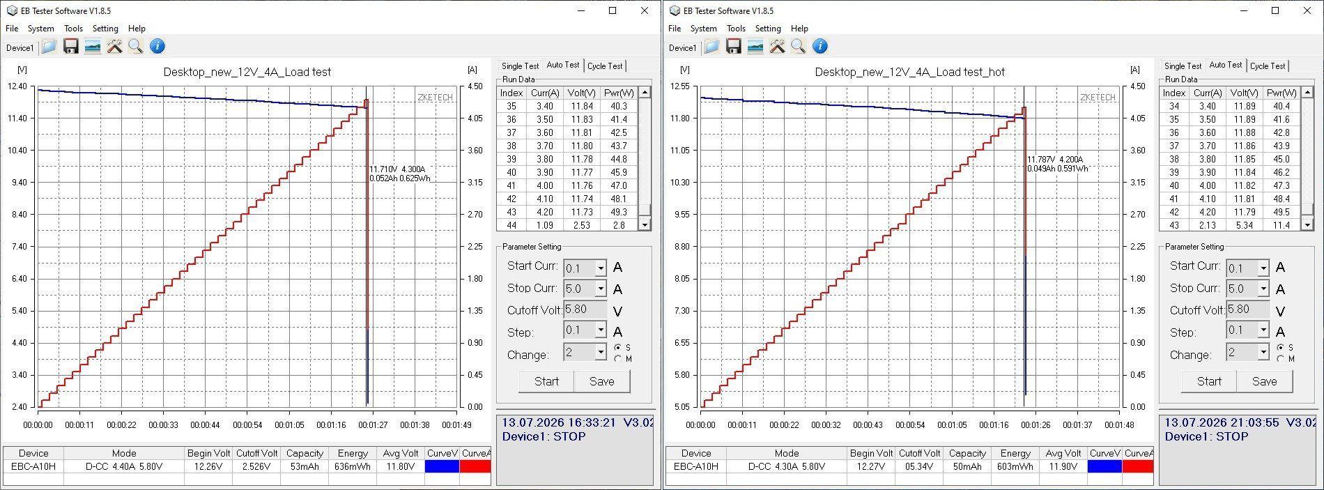
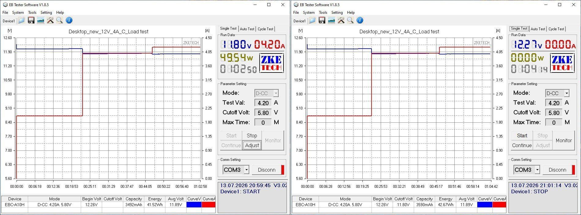
Since the protection current is set a little more "gently" here, the test ran at 2, 4, and 4.2 A.
The power supply holds its voltage very well. The cable does drop almost 0.5 V under full load, but the voltage still stays within tolerance.
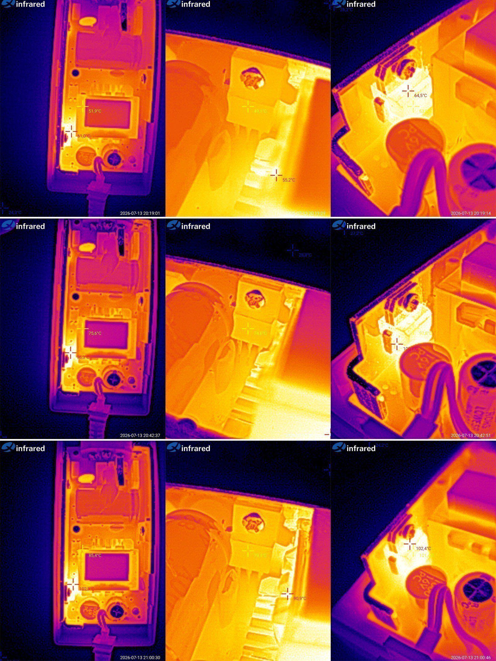
Temperatures.
2 A — transformer 52 degrees, transistor 49, diode assembly 65
4 A — transformer 76 degrees, transistor 75, and diode assembly 100
4.2 A — transformer 85 degrees, transistor 79, diode assembly 102.
As expected, the difference from the previous unit isn’t very large and is mostly due to warm-up, so the final readings are more representative. In any case, there’s still some headroom for higher ambient temperatures, even at maximum load, which is certainly good.
The even more powerful model, 12 V 5 A, is also simply labeled with a marker, since it’s a pre-production sample.
And as you can see, it’s based on the same board, but with a few changes.
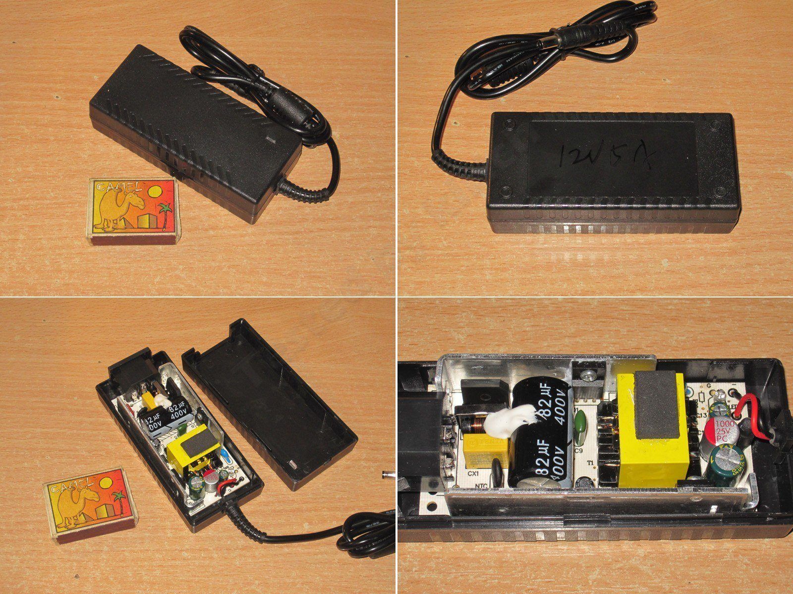
No changes on the input side; on the output side there are three capacitors instead of two. This was the factory engineers’ initiative. The PCB routing has also been changed slightly, again to improve things. The latter point is somewhat debatable, but I’m basically fine with it.
The inductor has higher inductance and current ratings; let’s see how it performs.
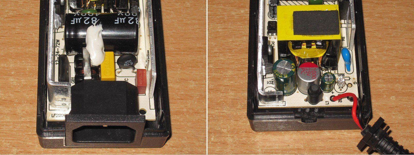
I couldn’t make out the transistor marking, but I did see that, at our request, they installed a synchronous rectifier on the output. I’ve actually already tried all this, i.e. The process goes like this: I get a sample, replace some components myself, show in photos what needs to be replaced with what, and send it to the factory. They make the changes, test it, set the protection current to our requirements, and send back samples. If everything looks good, it goes into production.
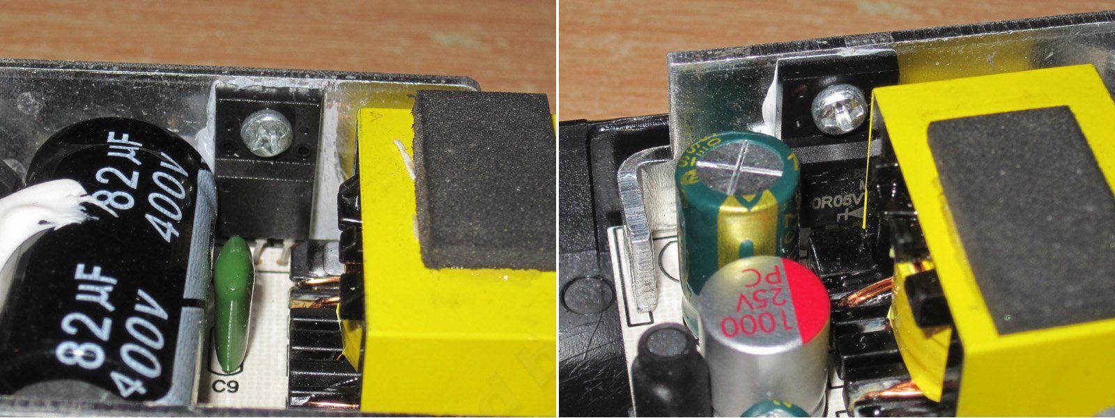
As I said, the board changes are cosmetic, but I should note that the output traces have been reinforced and the board layout has also been revised.
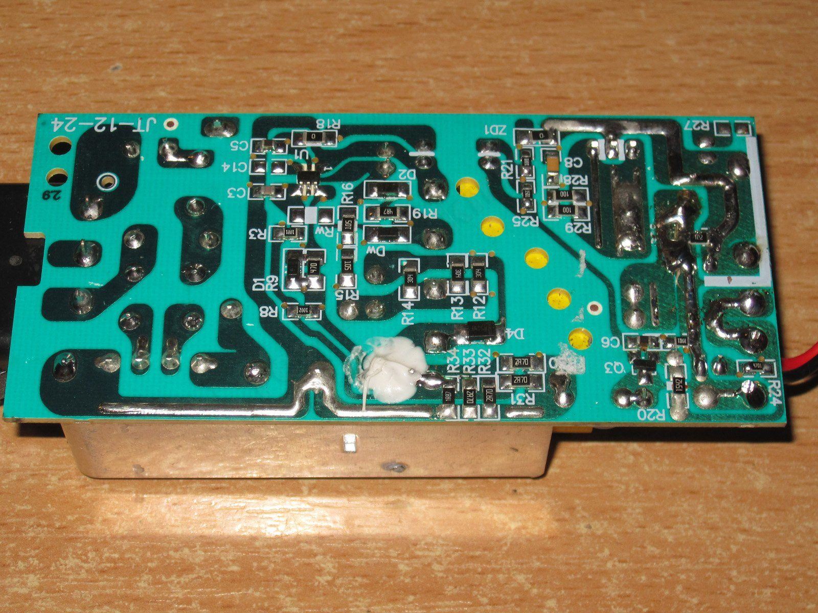
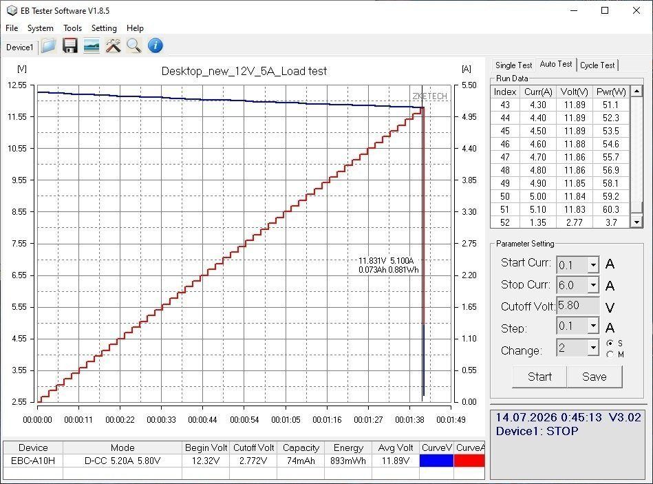
The protection current is right on the limit here: 5.1 A against the specified 5 A. We could try raising it to 5.2 A, but we can also leave it as is.
The high-frequency ripple is mostly around 15 mV, with a total peak-to-peak amplitude of 20 mV including the “spikes”—excellent.
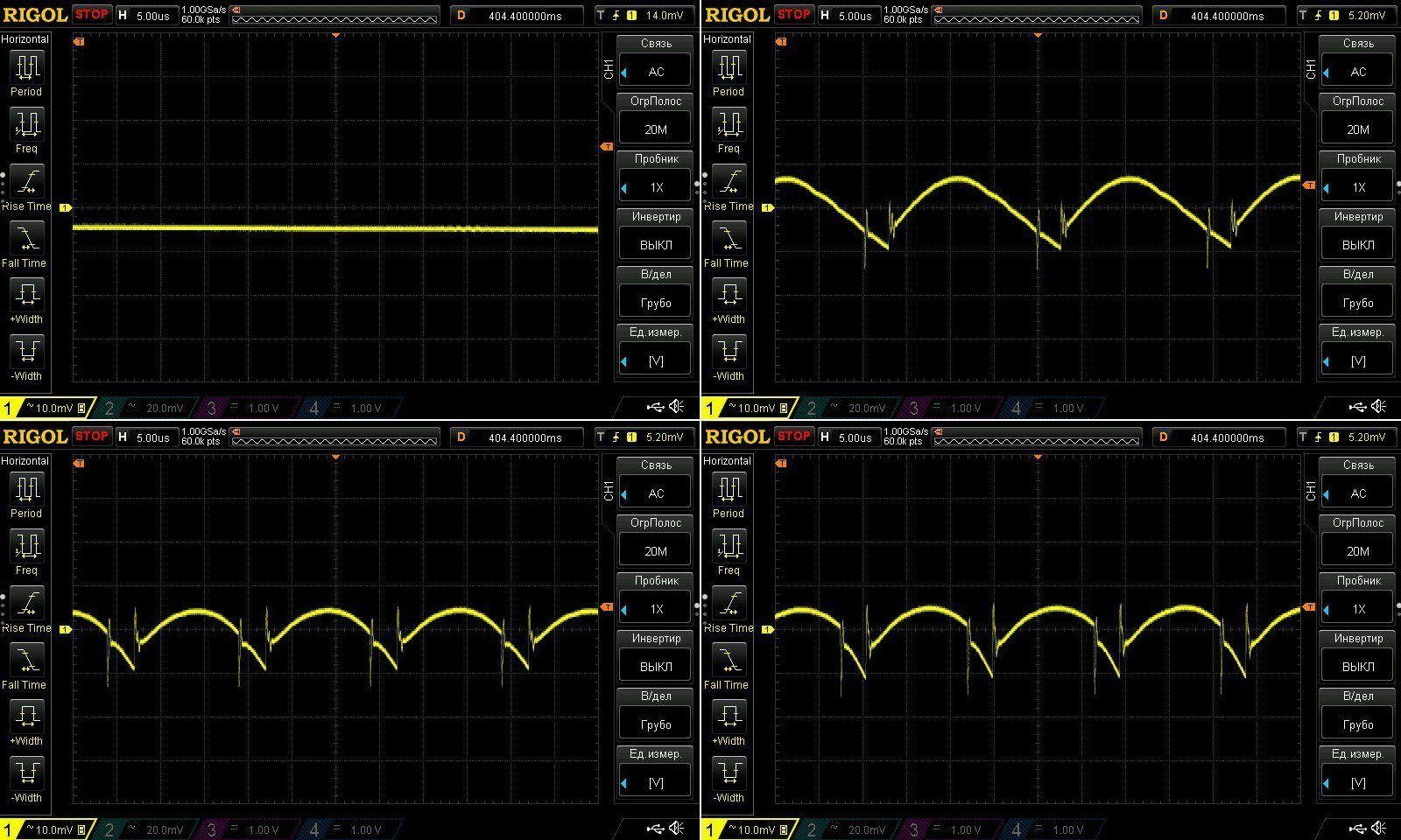
At 100 Hz, everything looks good except when running at the maximum current of 5 A. I should also note the relatively large ripple amplitude with no load, a characteristic of the “green” mode.
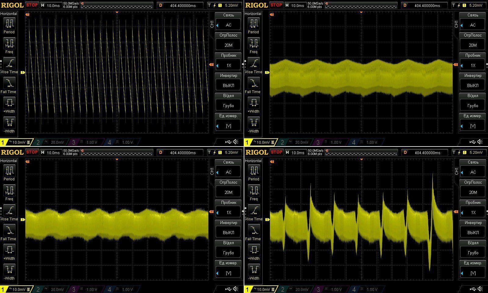
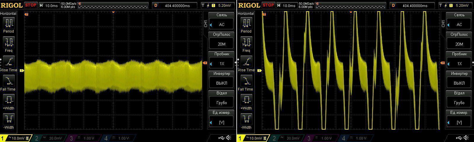
The large low-frequency ripple at maximum current is also a characteristic of how the protection works.
Here are the results at 4.9 A and 5.1 A. You can see that things get ugly at 5.1 A; after that, the protection shuts the power supply off.
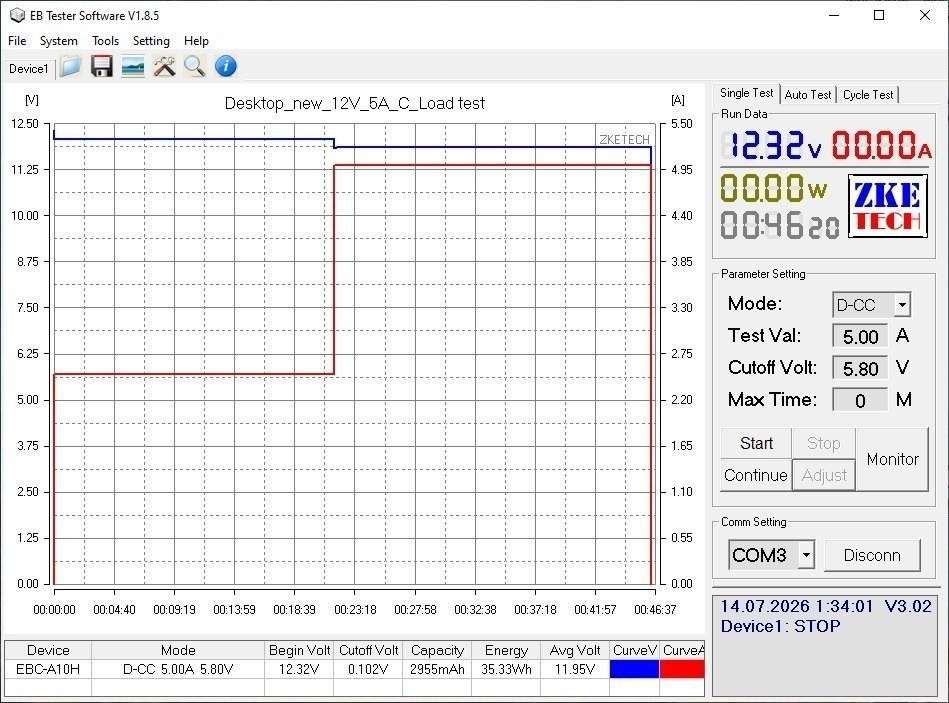
This test was run at 2.5 A and 5 A. I think the power supply itself stopped it after warming up, though honestly, I may have forgotten.
In any case, the total test time was 45 minutes, which is enough to assess it.
Temperatures
2.5 A: transformer 57 degrees, transistor 55, rectifier 52.
5 A: transformer 80 degrees, transistor around 80 (hard to see), rectifier 72 degrees.
The results are excellent. You may be wondering how a 5 A power supply can have lower component temperatures than the same 4 A model.
The thing is, it isn't quite the same. We replaced the diode assembly with a synchronous rectifier, improving efficiency and reducing the heat generated inside the case. Since the case has a fixed ability to transfer heat to the surroundings, we ended up with a more powerful power supply on the same board and in the same case, without much extra cost.
Technically, we could probably have pushed this board to 6 A, but we decided not to. It can realistically handle 5.5 A—I tested it—but we dialed it back a little by adjusting the protection parameters.
The next model is 12 V, 6 A. It looks quite similar to the previous ones, but is based on a different board.
I think it was originally a 5 A power supply, and there was an almost identical 6 A version. But after running the numbers, we found it was easier to take the 5 A model and upgrade it to 6 A.
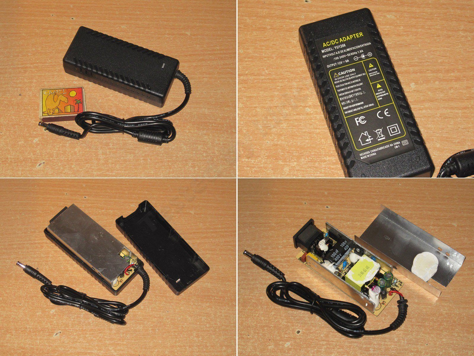
The input side also has a filter, a decent capacitor, a reasonably good transformer, and a proper Y capacitor.
On the output side, we suggested replacing one of the three capacitors with a polymer capacitor, swapping the diode assembly for a synchronous rectifier, and installing an inductor rated for higher current.
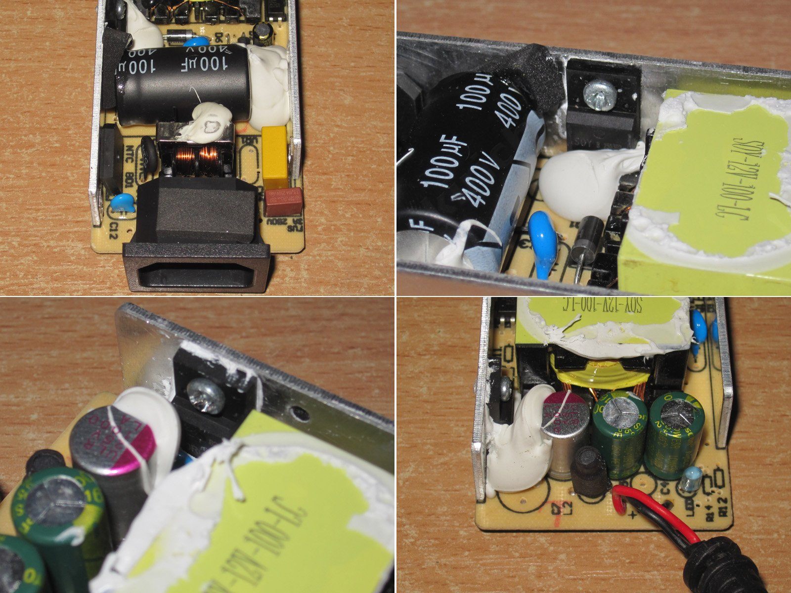
I have no major concerns about electrical safety; the board is similar to the previous ones. There are signs of hand soldering, but this is also a pre-production sample, so that's perfectly normal.
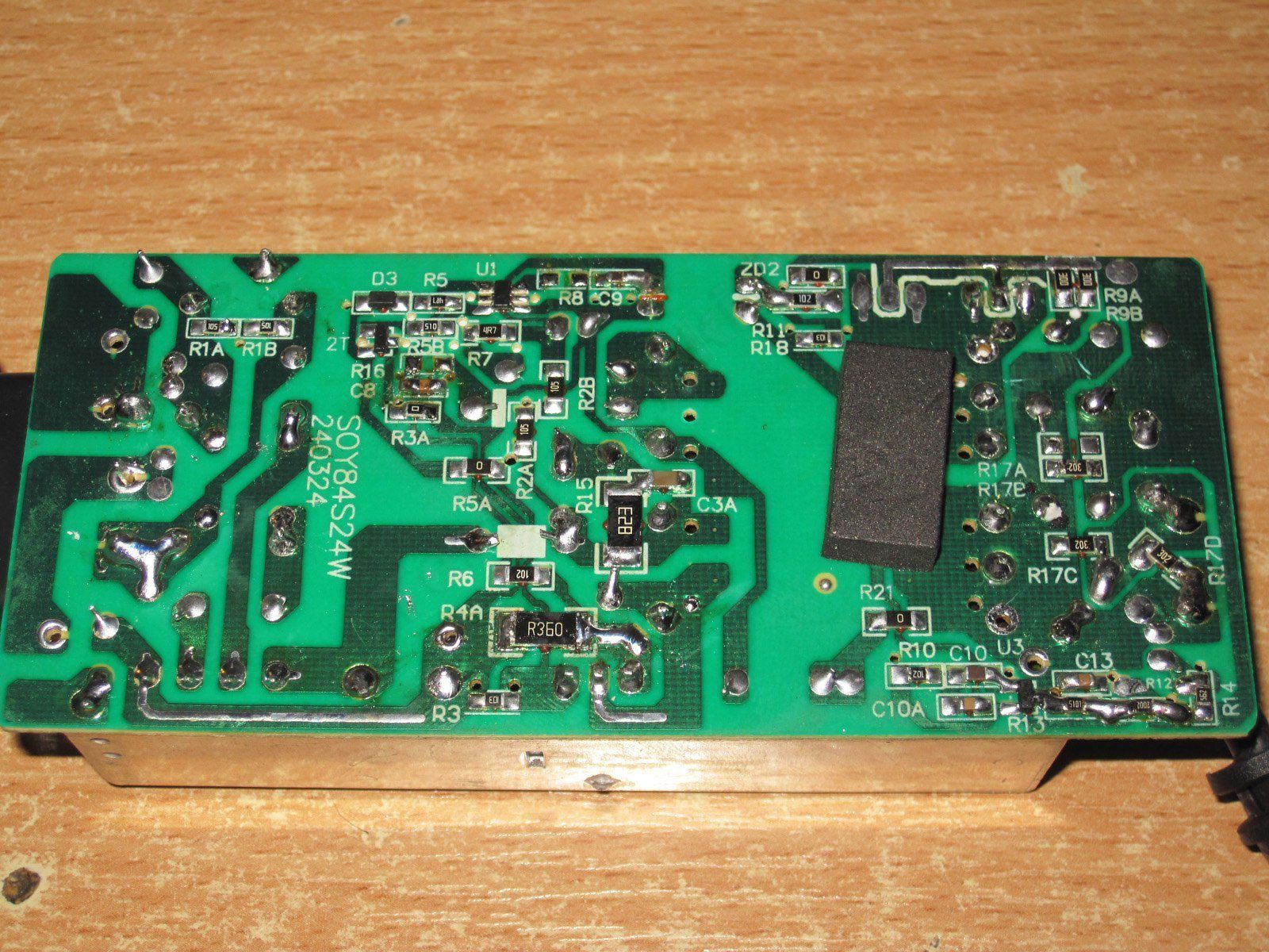
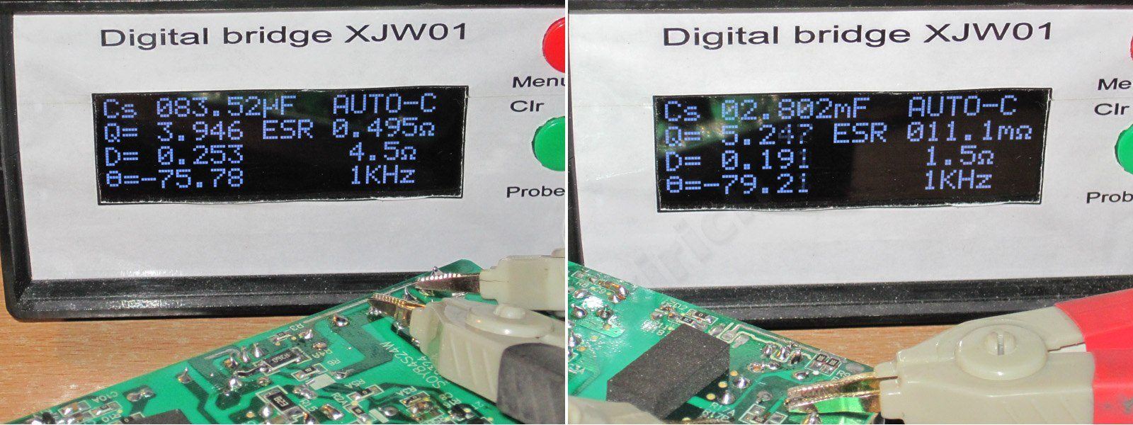
The input capacitor is 83 µF, and the output capacitors total 2800 µF. I have no complaints here at all; that's quite enough for the specified 72 W.
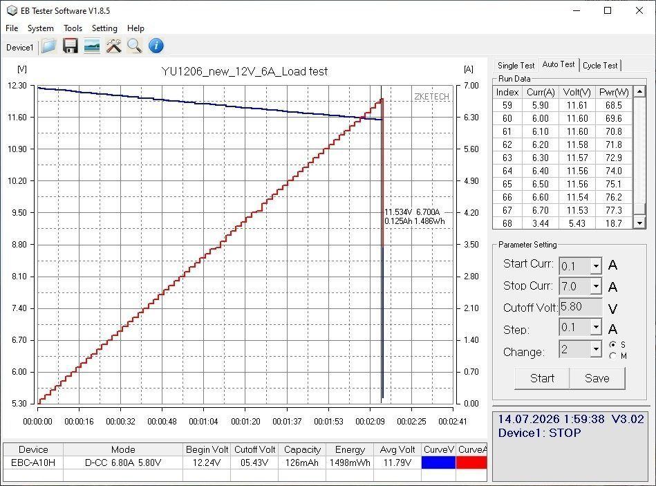
The protection current is set to 6.7 A. I think it may be worth lowering it further, to around 6.3–6.4 A.
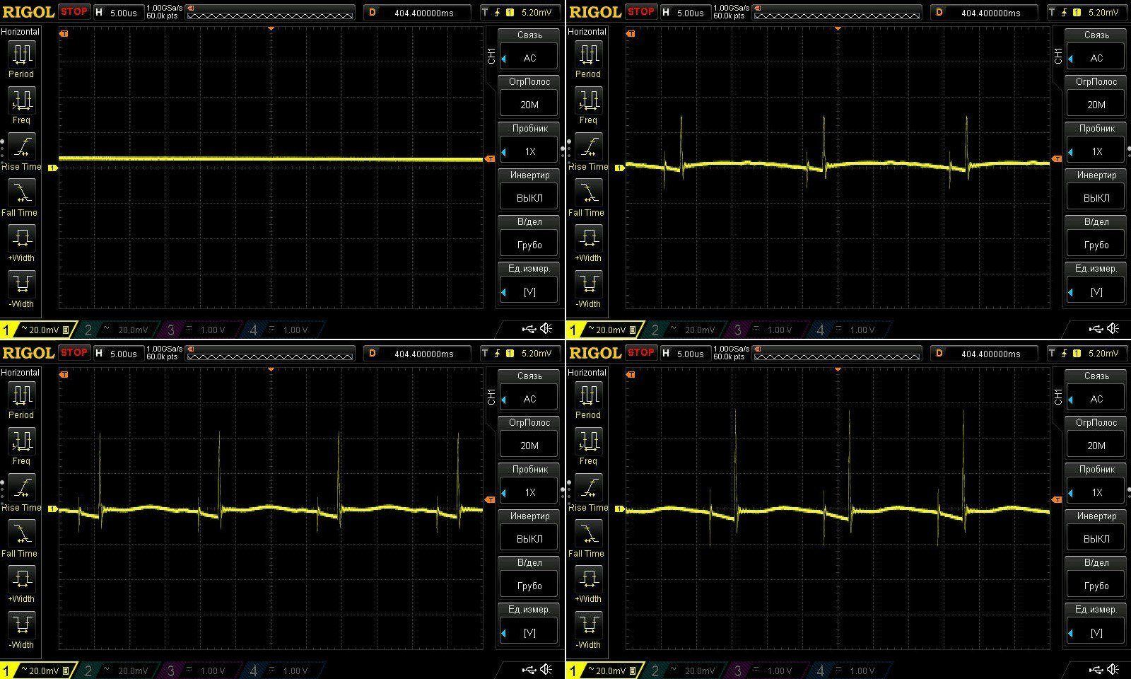
The high-frequency ripple looks a little odd. I think we should double-check the routing, because the main ripple is very small—less than 10 mV—but there are “spikes” with an amplitude of up to 60 mV.
Of course, in practice, all of this can be ignored, but you always want to make things as good as possible. That said, it would mean picking up the soldering iron and experimenting. So most likely, we'll leave it as is for now.
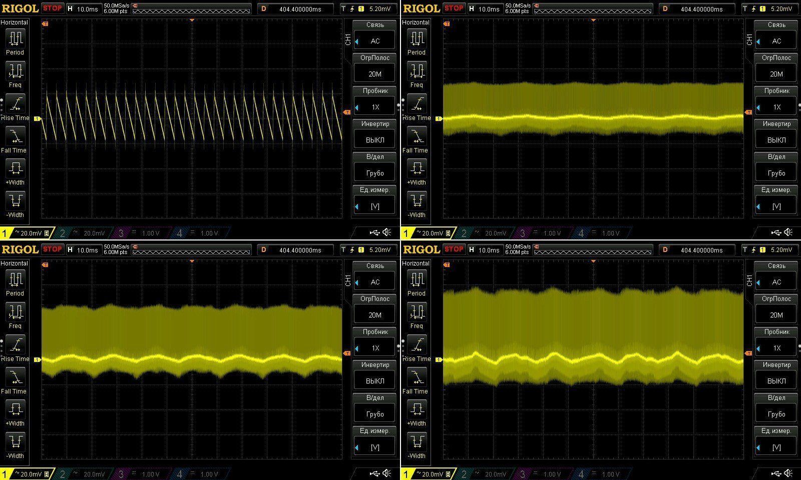
At 100 Hz, everything looks fine; I have no complaints.
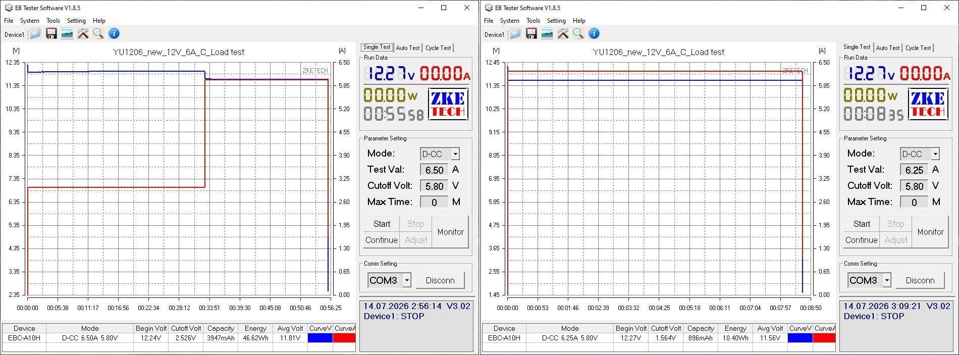
The warm-up test was run at 3 A and 6 A. Then I tried raising the current to 6.5 A, which triggered the protection. I then set it to 6.25 A, and the power supply shut off after 8 minutes.
So in practice, with the power supply warmed up, the protection current is set to around 6.2–6.3 A, and there's no need to change anything. The test was a little inconclusive, of course, but I think I did reach the limit in the end; it simply won't go any higher.
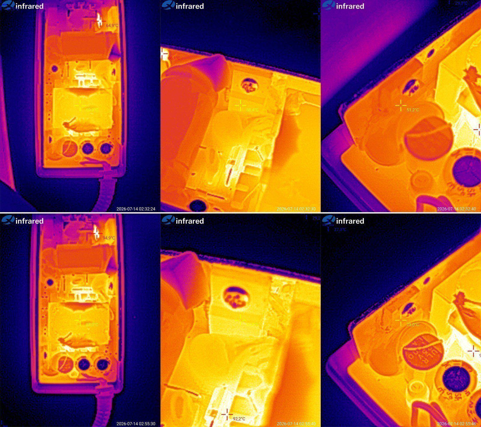
Temperatures at these currents:
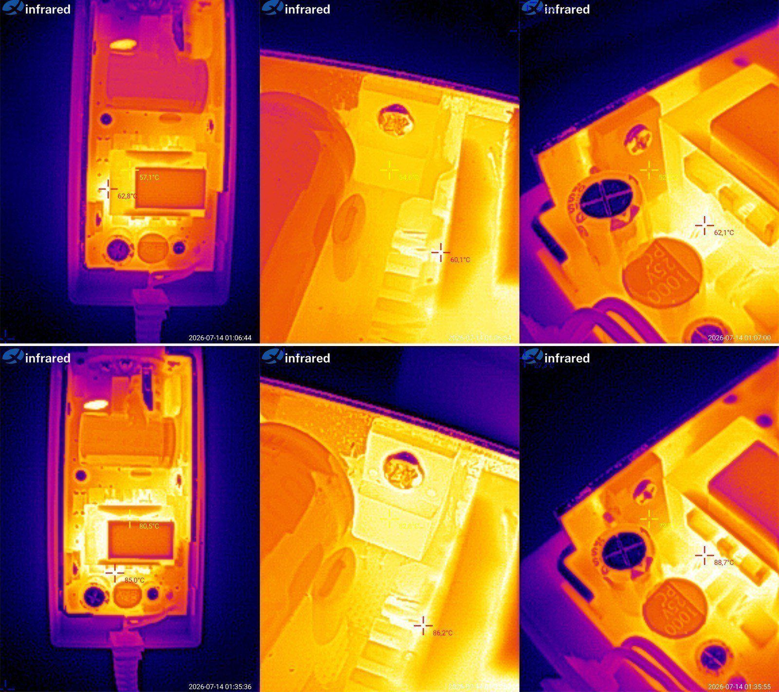
3 A — transformer 59 degrees, transistor 58, rectifier 51 degrees.
6 A — transformer 83 degrees, transistor 85, rectifier 75 degrees.
In my opinion, these are excellent results. There's plenty of headroom for a rise in ambient temperature. Technically, this power supply could easily handle 6.5 A, but no more; beyond that, it would simply hit the limits of the synchronous rectifier.
And here are a couple more models built around the same power supply.
First up is the 12 V, 8 A version. The manufacturer originally rates it at 10 A, but we decided it would be better to offer two models: the basic 10 A model is labeled as 8 A, and then there's the 10 A version.
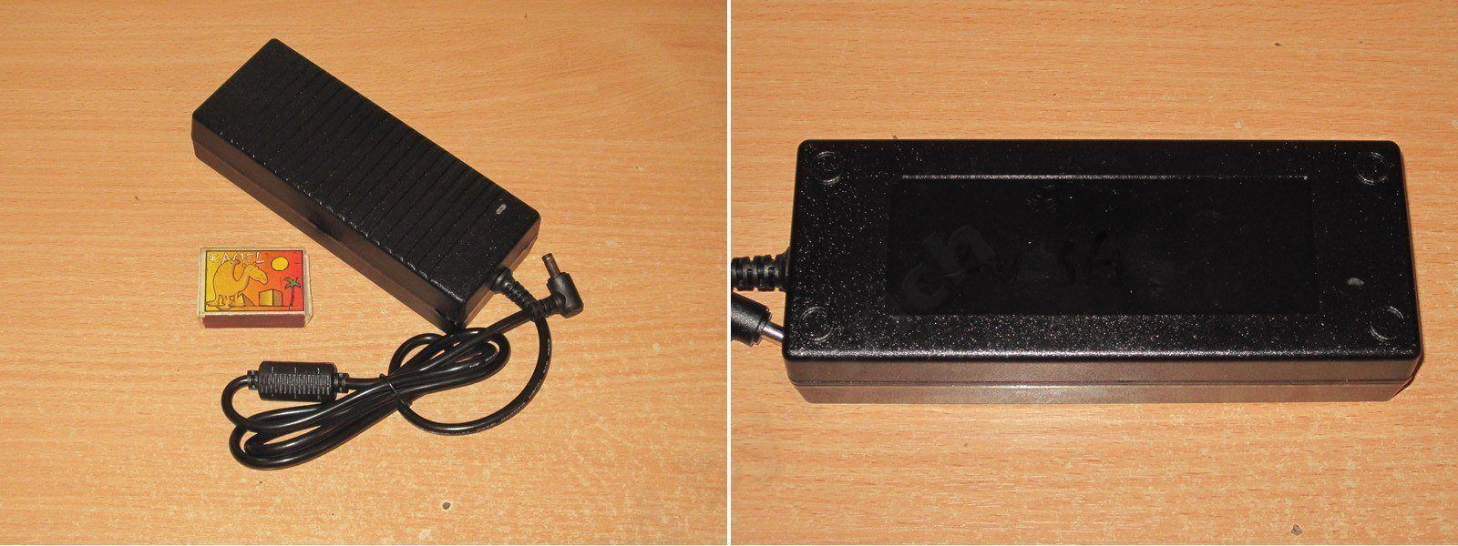
The case is more substantial here, and the board is made of fiberglass rather than phenolic paper. Though I think I may have already reviewed this power supply, but I could be mistaken.
Anyway, even a quick glance makes it clear that this is a noticeable step up from the previous models.
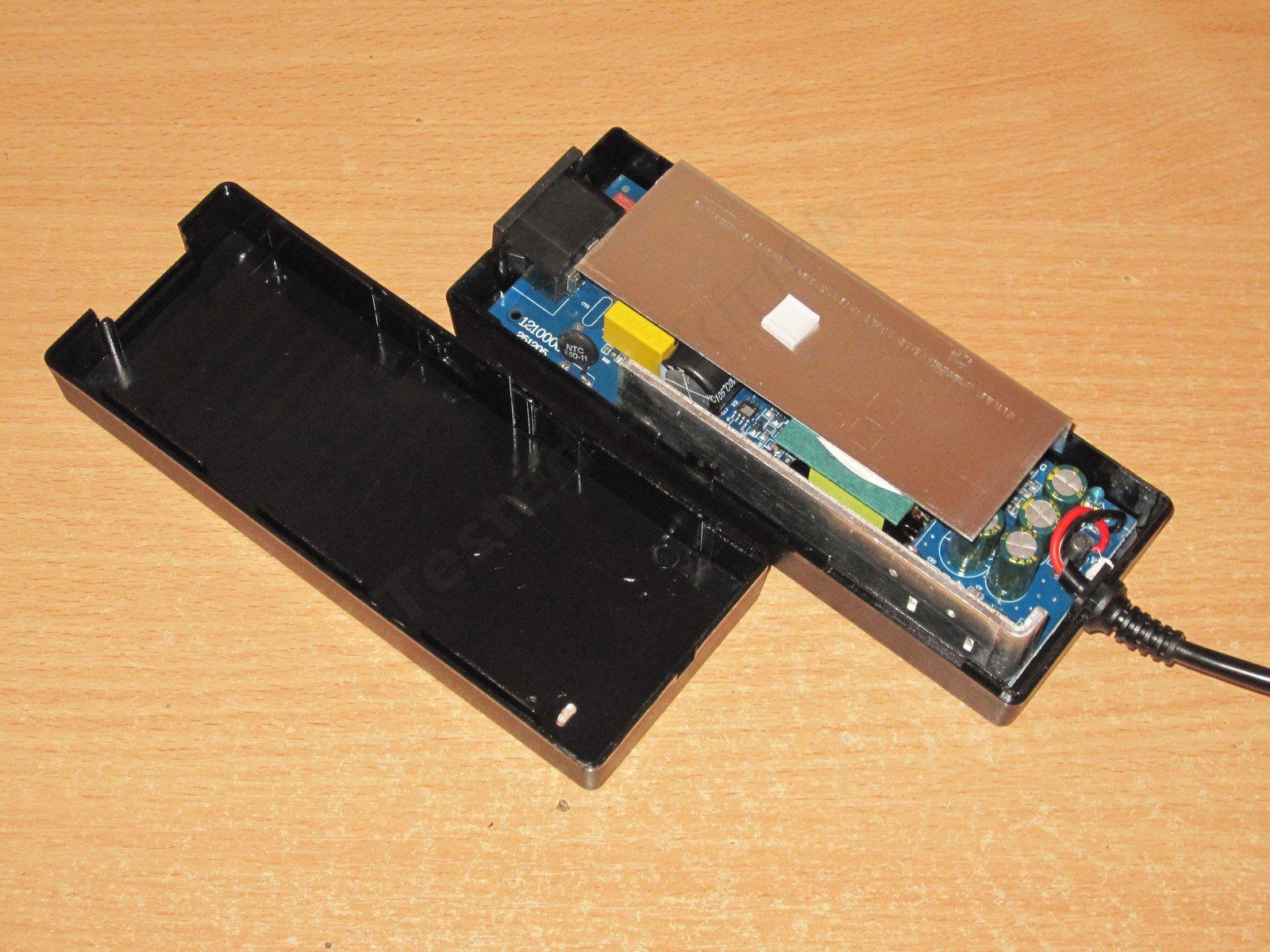
I didn't remove the heatsink; there's not much point, and you can already see that this one also uses a synchronous rectifier, which was there from the start.
The input capacitor is marked 120 µF, but measures about 100 µF. The output capacitance is 5750 µF, which is generally enough for 100 W.
We deliberately set the overcurrent protection to 8.5–8.4 A, both cold and hot. The idea was to fill the niche for 8 A models.
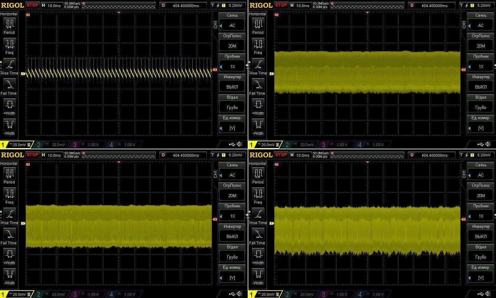
The ripple looks great here: 60 mV at 8 A, with no spikes at all. Five stars.
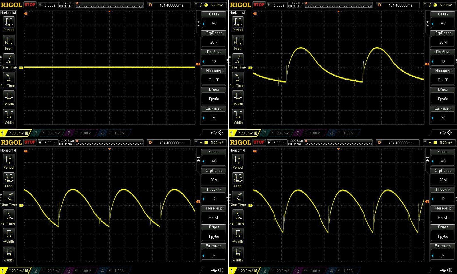
The low-frequency ripple looks good too, with nothing to complain about.
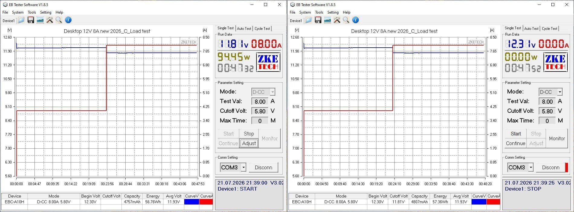
I tested it at 4 A and 8 A; there's no point going higher, since the protection threshold is only 5% above the rated current.
The voltage drops by half a volt under load because of the voltage drop in the wires. To be fair, though, the wires here are pretty good. The temperature-related variation is minimal, just about 10 mV.
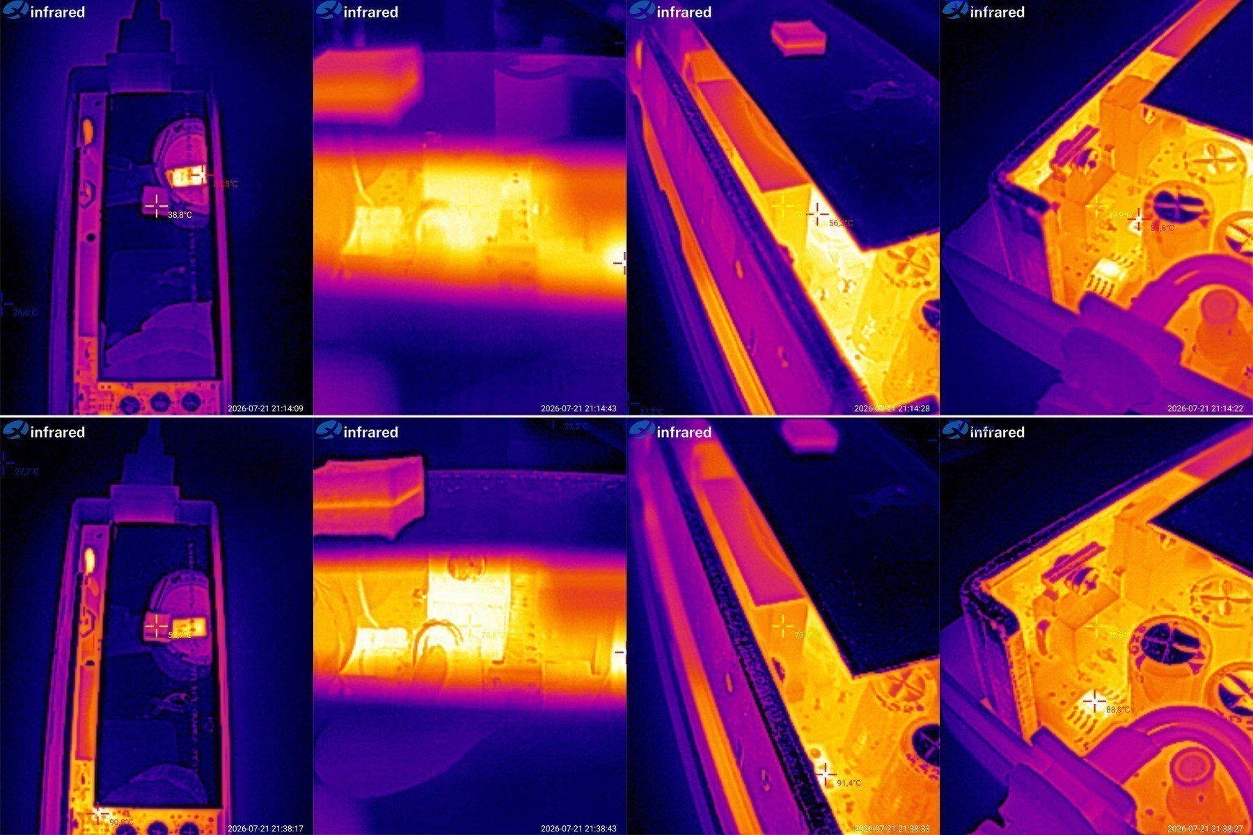
And here are the temperature test results.
4 A — transistor 51 degrees, transformer 52 degrees, rectifier about 50.
8 A — transistor 79 degrees, transformer 74, rectifier 76. The synchronous rectifier controller gets hot too, reaching almost 90 degrees.
Overall, all the temperatures are within the normal range; there's no sign of overheating.
The 10 A model is almost identical, though there are, of course, a few small changes.
I should mention that the factory offered two new models to replace this one, rated at 10 A and 12 A. I tested them and found that their new 12 A power supply runs hotter at 10 A than this older model does at the same 10 A. Naturally, we turned them down; there was no point.
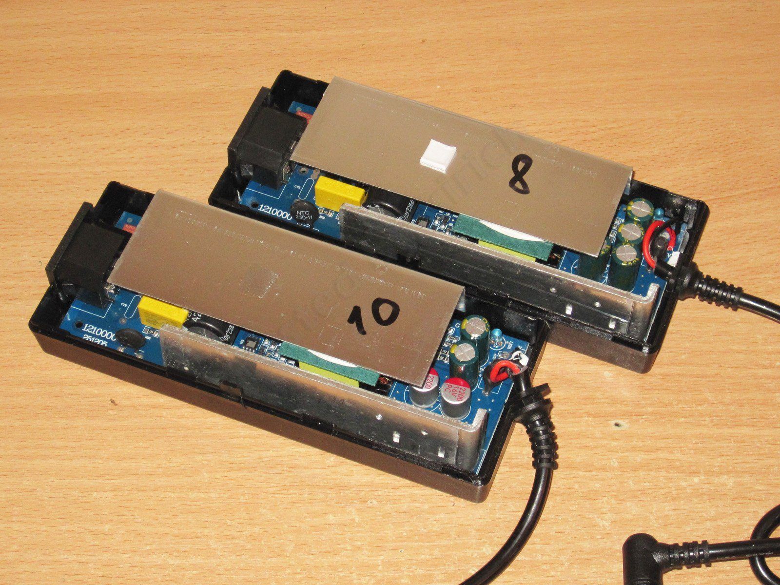
The actual differences are the output capacitors—the 10 A version has two 2200 µF, 16 V polymer capacitors—the different protection threshold, and a few other minor details I can't remember now.
The input capacitor is about the same, 100 µF, while the output capacitance is higher now, around 8300 µF, and the ESR is lower too.
The protection threshold is above 10 A, so I couldn't check it using the main load.
While checking the ripple, I also tested the shutdown current. It turned out that the power supply still works normally at 10.5 A, but shuts down at 10.6 A, which is more than acceptable. Initially, I thought this model's current was too high.
Well, the ripple here is really excellent: at 10 A, it's around 25 mV. There are some "spikes" with a total amplitude of up to 50 mV, but they can be ignored.
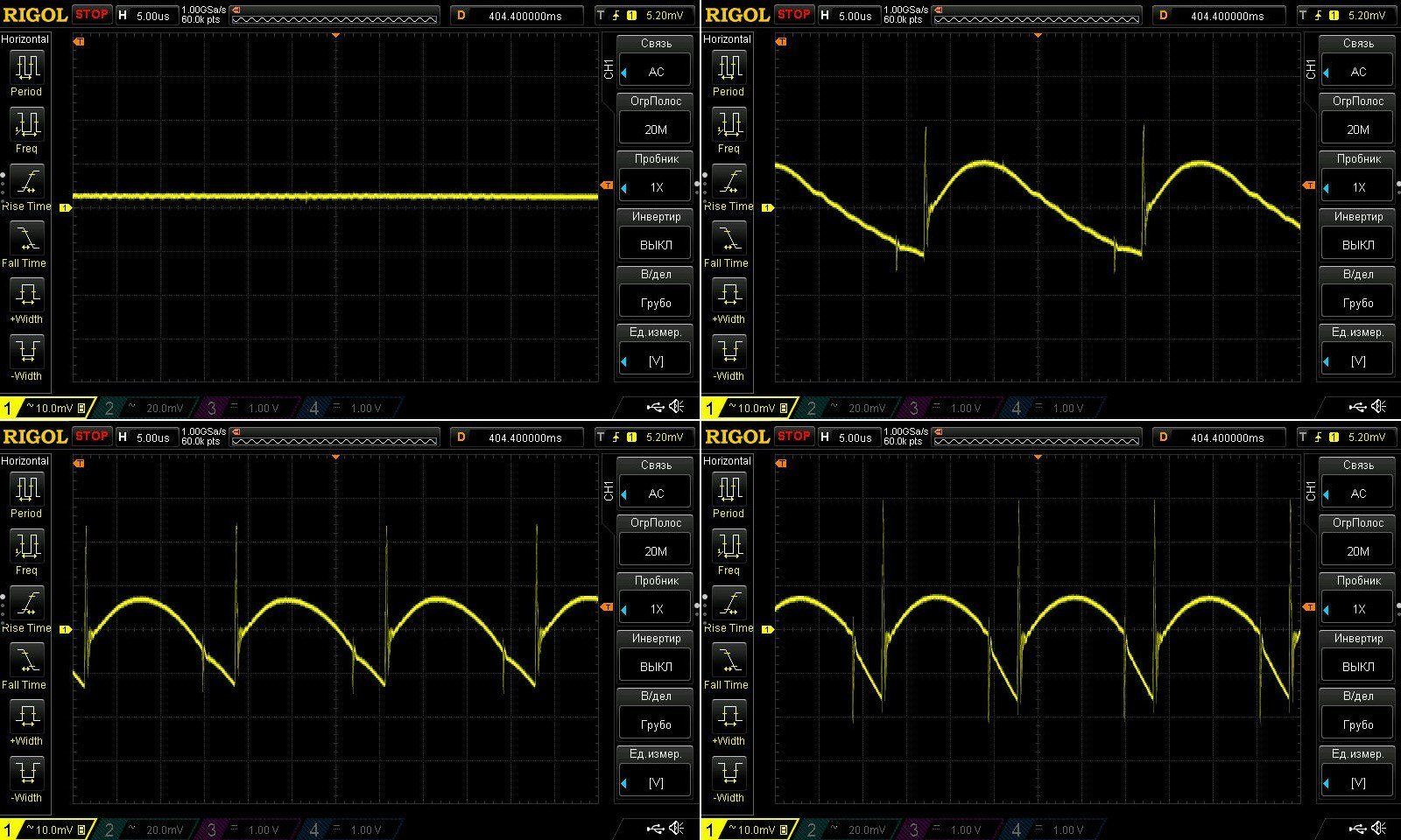
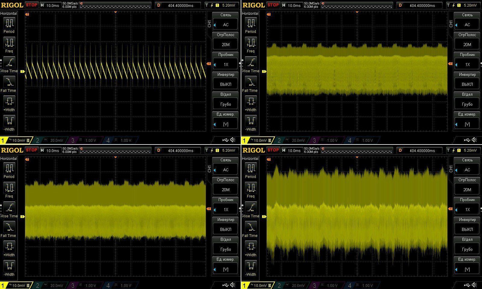
The low-frequency ripple is also fine. There's a slightly odd "fuzz," but compared with the overall scale, it's really negligible.
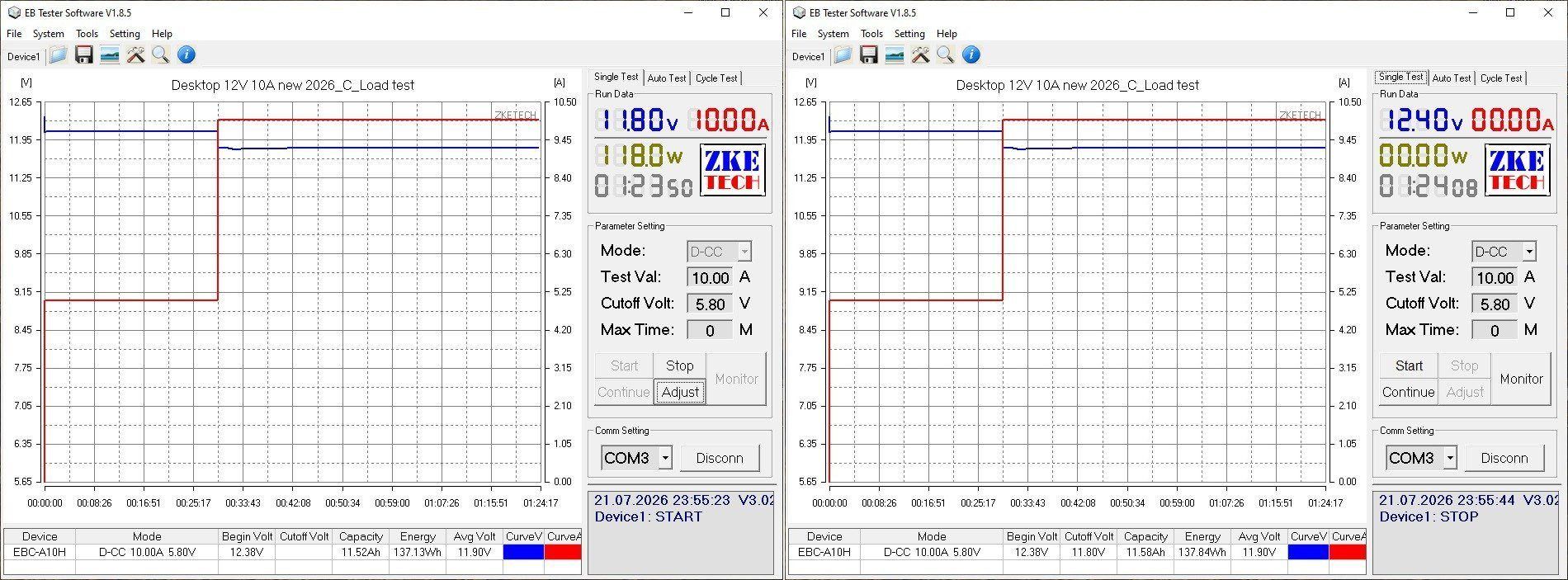
The test was run at 5 A and 10 A and took almost an hour and a half in total.
The output cable has a decent cross-section, but it still drops a full 0.6 V under full load. At 10 A, that's 6 W, which is a lot. The cable gets noticeably warm during operation, as does the plug.
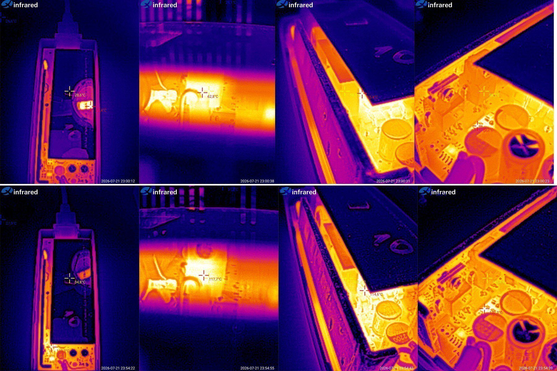
And, of course, component temperatures.
At 5 A: transistor 63 degrees, transformer 58 degrees, rectifier 56 degrees.
At 10 A: transistor 118 degrees, transformer 102 degrees, rectifier 105 degrees.
I tried to record the maximum temperatures in each case. I was a little surprised by how hot the components got at 10 A.
So, in practice, this power supply should have no trouble running continuously at 8–9 A, but I wouldn't use it continuously at 10 A.
Conclusions.
I hadn't reviewed any of the 24 V power supplies shown here before, but I do have some concerns about the low-power models. One seems to handle 2 A; the other is supposedly rated for 2 A but in reality is probably closer to 1 A. I think they still need some work.
The 2 A and 3 A desktop models are noticeably better, but it's clear that the factory tried to bring them in line with our recommendations for the 12 V models. I have concerns about ripple on the 2 A model. I don't think I had any complaints about the 3 A version: it has a polymer output capacitor and a synchronous rectifier.
The 12 V models are a little more predictable. I hadn't reviewed the 1 A and 2 A units from these revisions before, and they have the most issues. The 1 A version has a regular capacitor instead of the correct Y capacitor, which is unsafe. The 2 A version showed signs of overheating at maximum power.
The 3 A, 4 A, and 5 A versions are all the same power supply, with varying degrees of modifications and corrections, so they perform more or less alike: no overheating, a reasonable level of electrical safety, and low ripple. These models were made to our recommendations.
The 6 A version is very similar and was also made the way we wanted, so there are no issues with these models.
The higher-power versions are a little more complicated. I have no complaints at all about the 8 A version. The 10 A version runs closer to its limits. Even reducing the current to 9–9.5 A makes everything completely stable, but that's the only issue. The build quality and all the other parameters are excellent; I especially want to point out the very low ripple on the 10 A version.
Yes, I focus on temperatures at 100% of the rated load, but we all know that power supplies shouldn't be run continuously right at their maximum power. Still, as you could see in the review, the 3–8 A versions can run continuously at 100% load without any trouble. And that's exactly what we're aiming for.
Someone once asked me in the comments: what's the point of these reviews if the Chinese manufacturers will send something different next time? That's not the point at all. The whole idea is that we shouldn't have to depend on whatever they send us; instead, we should know exactly what we'll get, because the factory makes all the necessary modifications to meet our requirements.
That's also why we're considering making our own power supplies, most likely in Ukraine. To keep costs down, we may use some ready-made components—at least the most troublesome one, the transformer, and the enclosures. Ordering molds is expensive :(
That's probably all for today. This turned out to be quite a long one; I hope it was useful, and thanks to Vitaly for the productive collaboration :)
I'll add links to these power supplies in the store later, as they become available.
This model is included in the summary table: Comparison of power supplies: ripple, efficiency, and temperature rise
The figures from this review are in the measurement database: Power supplies
Calculate manuallyAll calculators
Discounted products
You may be interested in



Discounted products
Support the project
All the content on the site and the advice are free, but we’d be grateful for your support of the project and the channel!
Comments1
Discuss on the forumHave a question or some experience to share? Discuss the article with the author and readers: the forum is a convenient place to share schematics and photos.
Go to the forumOnly registered readers can comment. It takes a minute to sign up, and you can log in with the same account you use on the forum.
Log inRegister
Comments are published in their original language.