
Atorch BW600, another addition to the DL24MP load lineup
$26.5
To keep up with new posts on the blog, I recommend following me on Instagram. I’ll post notifications about new articles there, and might also write about something interesting from time to time: link to my account
You can also subscribe to updates and new articles on the Telegram channel - https://t.me/KirichBlog
I’ll start this review not by describing the new product, but with a message, because getting through to the engineers via the manager is extremely difficult.
Dear Atorch engineers, I have a huge request, please contact me via email - kirichserv@gmail.com, I need to talk to you both about my task and about improving your device. It is important for me to talk specifically with the developer of the electronic load series.
尊敬的 Atorch 工程师,我有一个非常重要的请求,请通过电子邮件 kirichserv@gmail.com 联系我。我需要与您讨论我的任务以及改进您的设备。与电子负载系列的开发人员进行具体的沟通对我来说非常重要。
But back to the review.
As I mentioned earlier, I ordered the full version of the load (or so I thought at the time), which includes the main module and three power modules. I ordered two sets: one I bought myself, and the other was sent for review. I would have ordered just the main board, but it wasn’t available anywhere at the time.
I picked up a fairly large box at the post office, weighing about 4 kg. Inside were two main modules, six power modules, and a couple of power supplies.
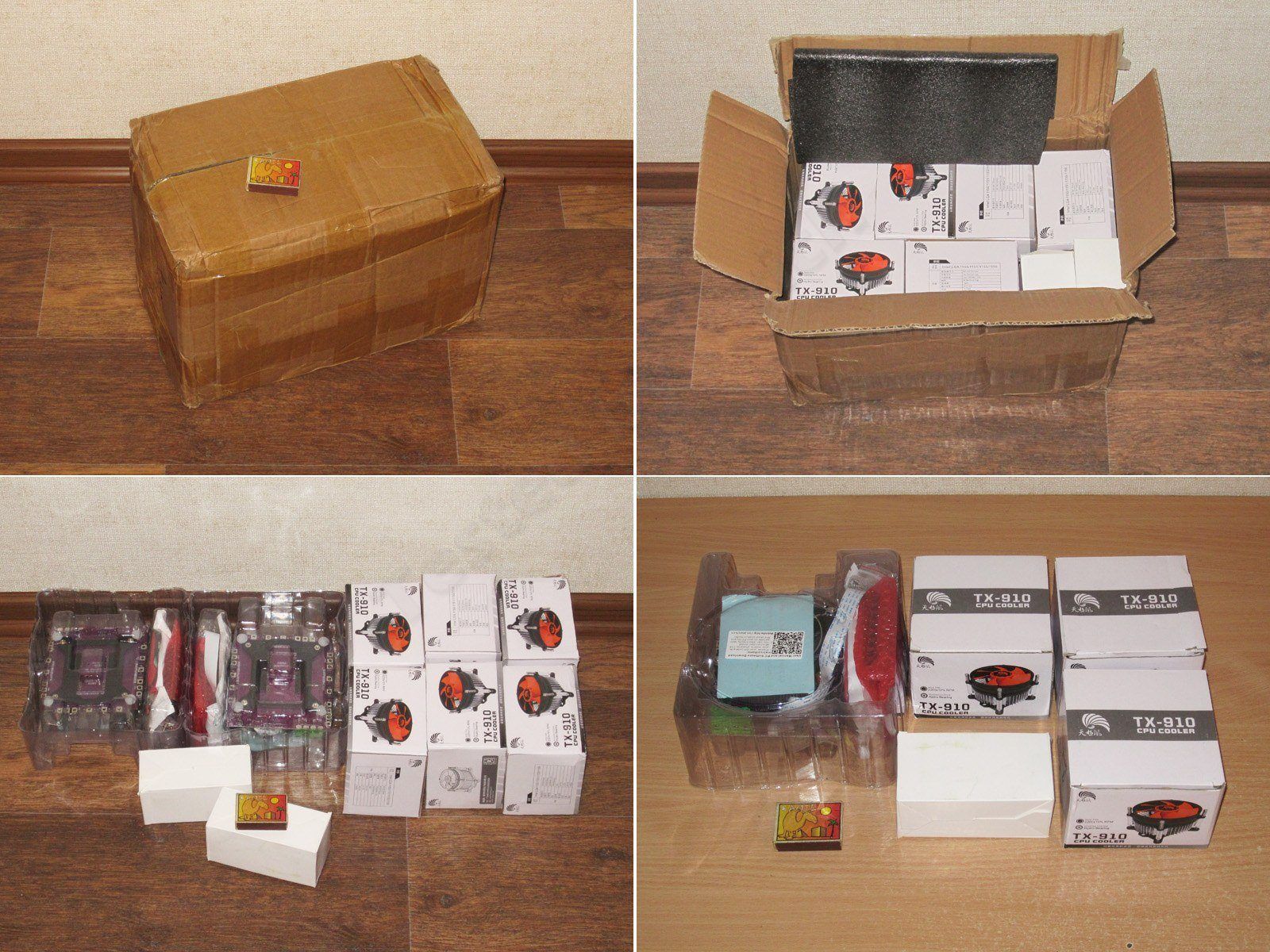
Since the sets are identical, I’ll describe just one of them.
The set includes:
1. Main module rated for up to 150 W and 30 A
2. 12 V power supply
3. External temperature sensor
4. A pair of test leads with alligator clips
5. USB cable
6. Power supply adapter
7. Adapter for testing power supplies with USB connectors
8. Mounting hardware
9. A guide to four-wire measurements.
There are already some additions to this set, which I’ll cover either during the review or at the end.
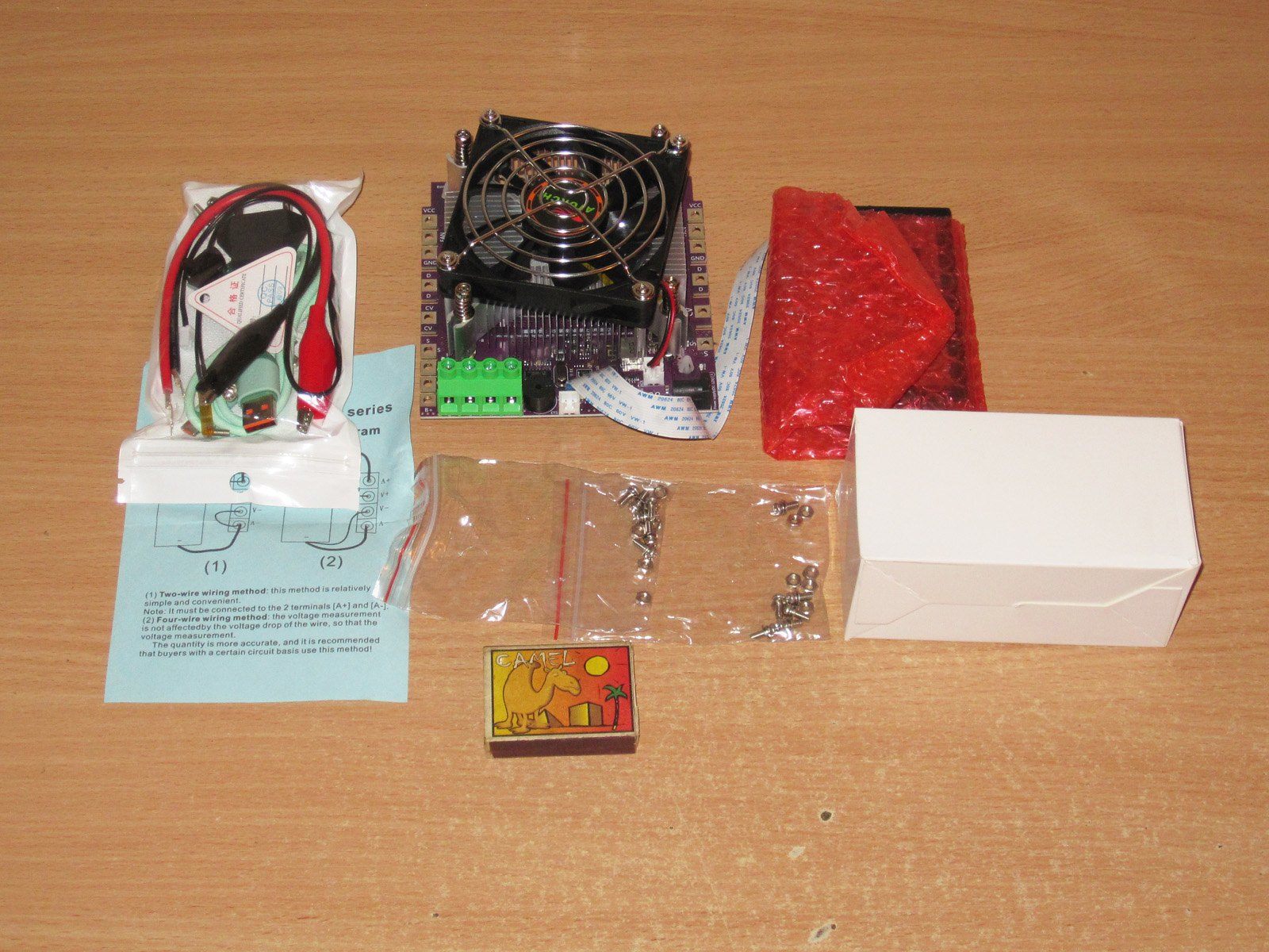
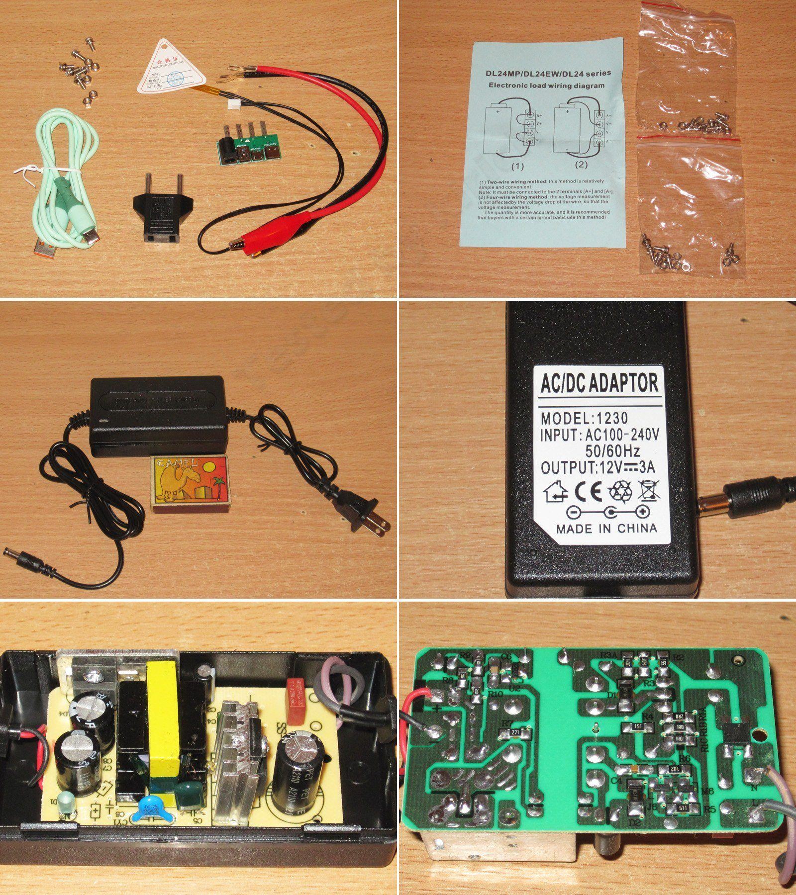
1. The main package contained six screws, six nuts, a pair of leads with alligator clips, an adapter board, and an adapter.
2. They also included two extra bags, each with six screws and six nuts.
3–6. The power supply is rated for up to 3 A, though I personally doubt that figure. By the way, single control modules now come with 12 V, 1 A power supplies that have fairly decent used boards of two different types. This might be useful to someone.
And here’s the main module with the display.
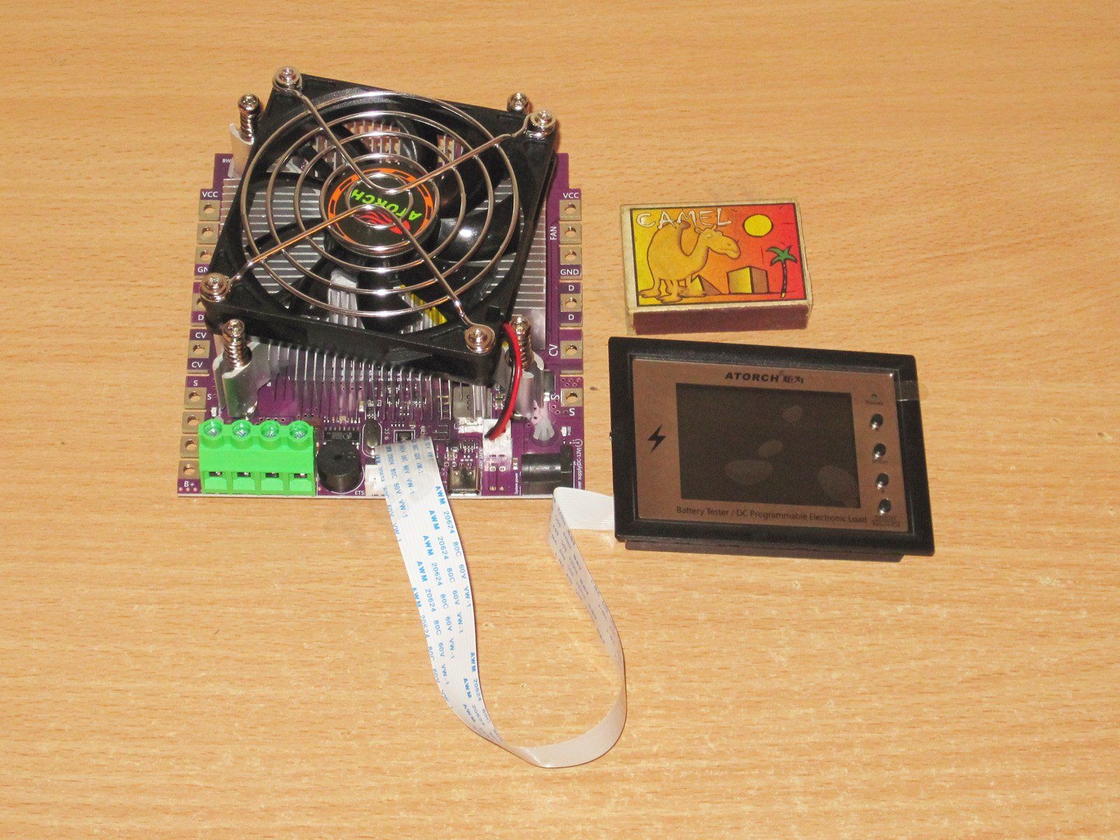
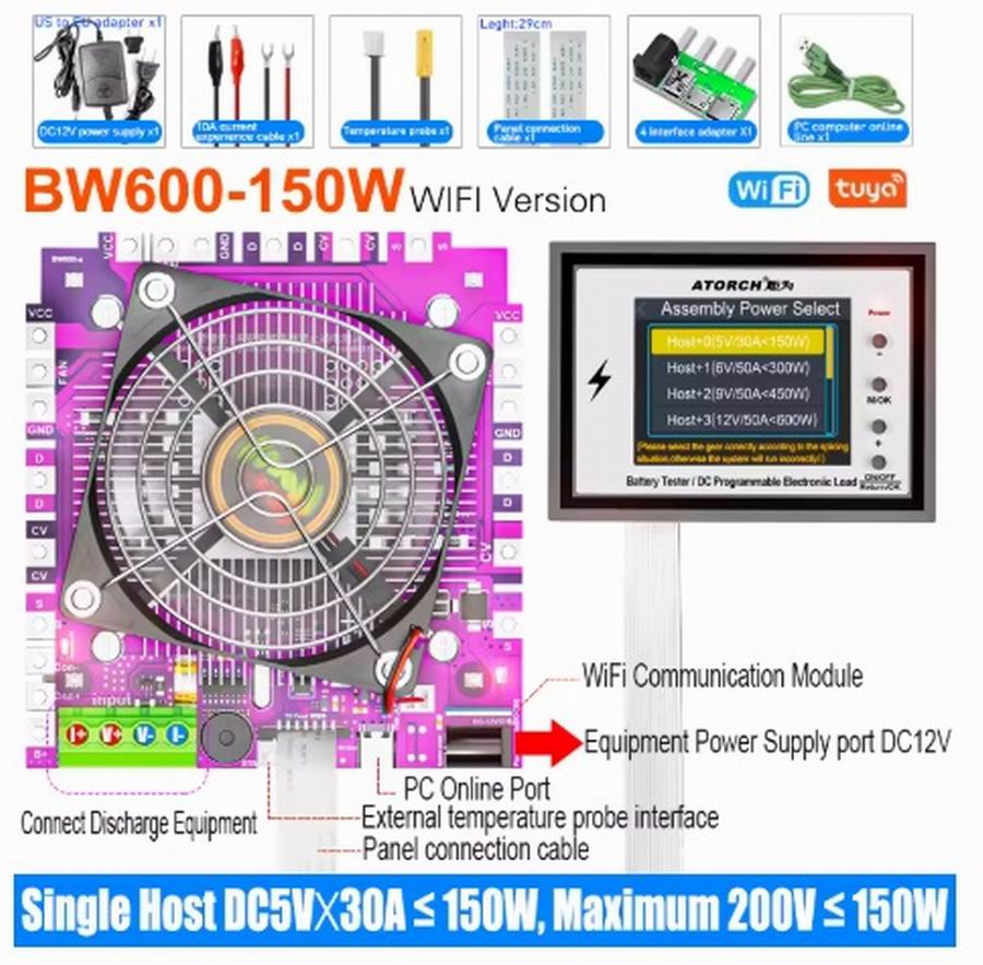
Despite looking similar, it’s fundamentally different from the DL24MP. For the most part, the BW600 is an expanded version of the BW150 load.
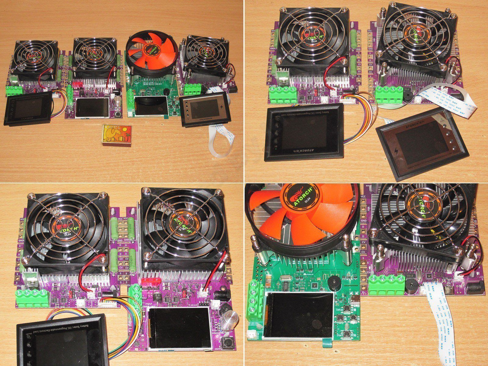
1. DL24MP, DL24EW, BW150, BW600.
2. The DL24MP and BW600 side by side. Essentially, all that remains from the old version is the form factor and the external display module.
3. The DL24MP and DL24EW, on the other hand, use the same circuit design and components. The main difference with the 24EW is that it has a charging control function and the display is mounted directly on the main board.
4. The BW150 and BW600 also have a lot in common and use almost identical components. But here the developers decided to give both versions charging control. The key difference between the models is that the BW600 has an external display module and can connect to external power modules. The other differences, such as the power supply and shunt rating, are mostly cosmetic.
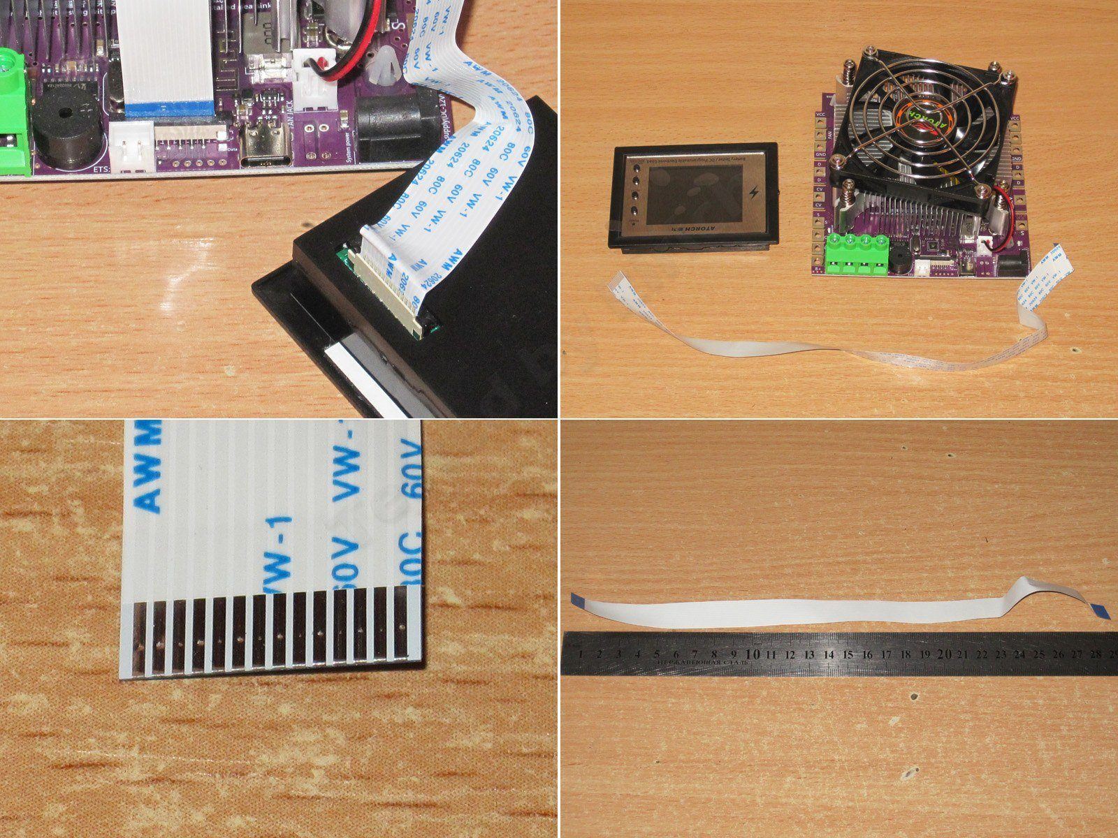
The front panel is now connected with a 14-pin, 1 mm-pitch flat ribbon cable instead of individual wires. As I understand it, the developers simply routed 10 conductors to the display and added four more for the buttons, making 14 in total.
Somewhere I read that the cable is 29 cm long, but it’s actually the standard 30 cm length, straight-through (don’t confuse it with a reverse cable). It’s quite convenient, though 30 cm is far too long for my purposes, so I’ll buy the same cables in a 10 cm length.
Be careful when removing or inserting the cable. First lift the latch on both sides, then push the cable all the way in, and finally lower the latch. A common mistake is trying to pull the cable out without lifting the latch; at best, you’ll damage the cable.
Speaking of the front panel, I don’t know what kind of exceptionally gifted person designed it, but swapping the + and − buttons is just cruel. It used to make sense: + at the top, then select, then −. Now − is at the top, and the third button is +.
At the very least, this is illogical: it would make more sense to have + at the top. At worst, it’s simply inconvenient—and if you’ve already used the 24МР load, this will drive you crazy.
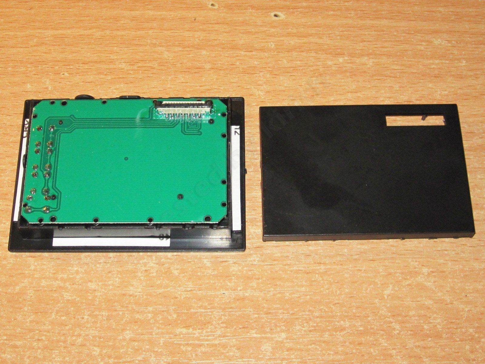
Since the controller is now on the main board, the display module contains only the display itself and four buttons. Even the buzzer has been moved to the main board. The display is a standard 2.4-inch model, but you can also use a 3.5-inch display. The resolution and even the pinout are the same; you’ll just have to fit it into your own enclosure.
Since this is mostly the same as the BW150, there’s no point repeating everything, as the firmware is about 90% identical.
On startup, it prompts you to choose a language. English is selected by default, and you can also disable this prompt here.
Next is a screen with a QR code linking to the software and manuals. There’s no point following it for now: for some reason, there’s no PC software there, and the manuals aren’t quite the ones we need. However, the CL24 software works with this load.
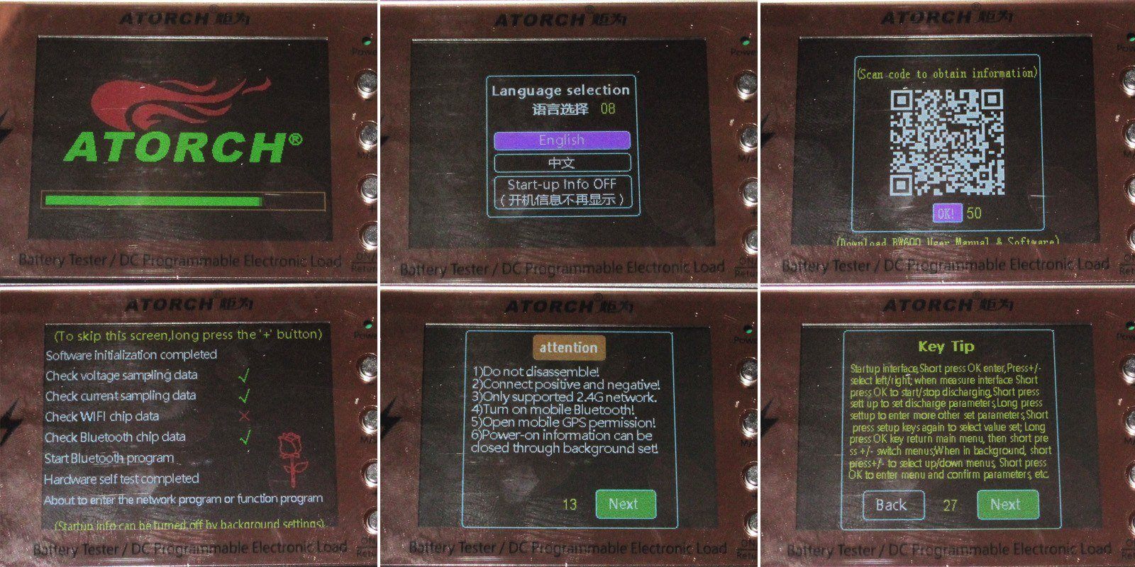
If you looked closely at the previous photos, you probably noticed the red cross next to WiFi.
The thing is, my load is the version without WiFi. I only found that out later, but it turns out versions with WiFi are already on sale too. It’s easy to tell them apart: there should be a submodule next to the power connector. Mine just has an empty spot for it—they cut costs on my unit :(
Personally, I don’t see much point in WiFi, since it’s for Tuya. What I’d really like is a connection to a PC, but I’ll talk about the PC software later.
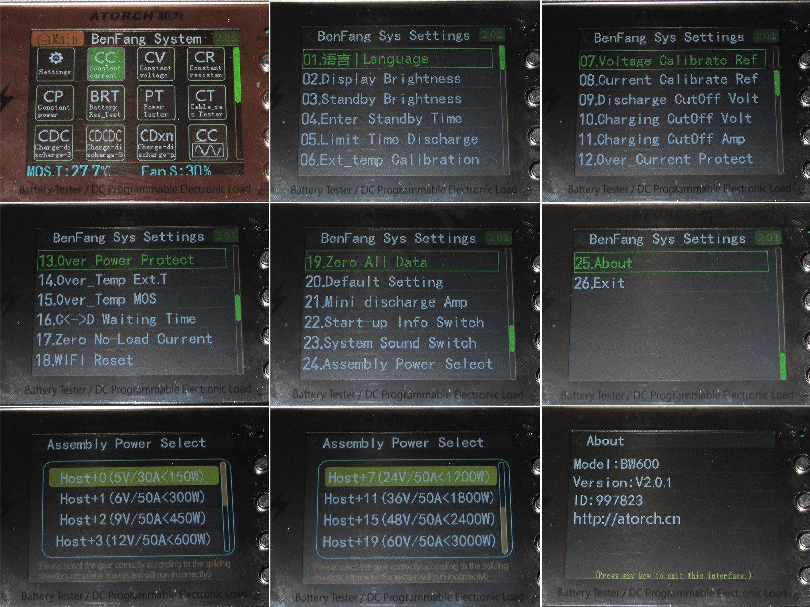
1. Next is the home screen, where you can select the operating mode. CC mode is selected by default, at least initially. To return to this menu, press and hold the bottom button.
2–6. Menu and item descriptions:
1 - Menu language
2 - Display brightness
3 - Display brightness in standby mode
4 - Time before entering standby mode
5 - Discharge time limit
6 - External temperature sensor calibration
7 - Voltage calibration
8 - Current calibration
9 - Discharge cutoff voltage
10 - Maximum charging voltage at which the load considers charging complete
11 - Current at which the load considers charging complete
12 - Maximum discharge current
13 - Maximum discharge power limit, selected according to the number of power modules
14 - Maximum temperature for the external sensor
15 - Maximum temperature of the main module’s power section
16 - Pause between charge-discharge and discharge-charge cycles; 1 minute by default
17 - Current meter zeroing, usually not needed.
18 - Reset WiFi settings
19 - Clear all accumulated data
20 - Restore default settings
21 - Minimum discharge current, essentially the minimum setting limit
22 - Show/hide information on load startup; you can safely turn it off.
23 - Disable the buzzer
24 - Settings for the number of external power modules
25 - Firmware information
26 - Exit. In fact, you can leave the menu simply by pressing and holding the bottom button.
7, 8. You can select the number of power modules now; there’s no need to use jumpers anymore. Options range from one external module and 300 W to 19 external modules and 3000 W.
9 - Firmware version and serial number.
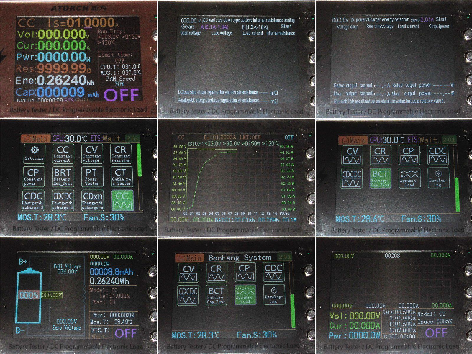
Overall, the menu is much like the one on the CL24 and BW150, but there are some differences.
1. Main screen in CC mode
2, 3. Battery internal resistance measurement and power supply testing modes; these are unchanged
4, 5. As with the versions mentioned above, you select graph mode from the main screen, not the settings menu. There’s a button with the same name, but with a sine-wave icon.
6, 7. Here’s a new mode: battery testing. It’s actually much the same as before, but possibly more convenient. Set the battery’s upper and lower voltage limits and the discharge current, and this screen will show not only the discharge process but also the percentage of charge remaining in the battery.
8, 9. Another new and interesting mode: the load automatically cycles through four load-current settings, along with the duration of each stage (one setting for all stages, minimum 5 seconds). During the test, the load does this automatically. I’ll show you later.
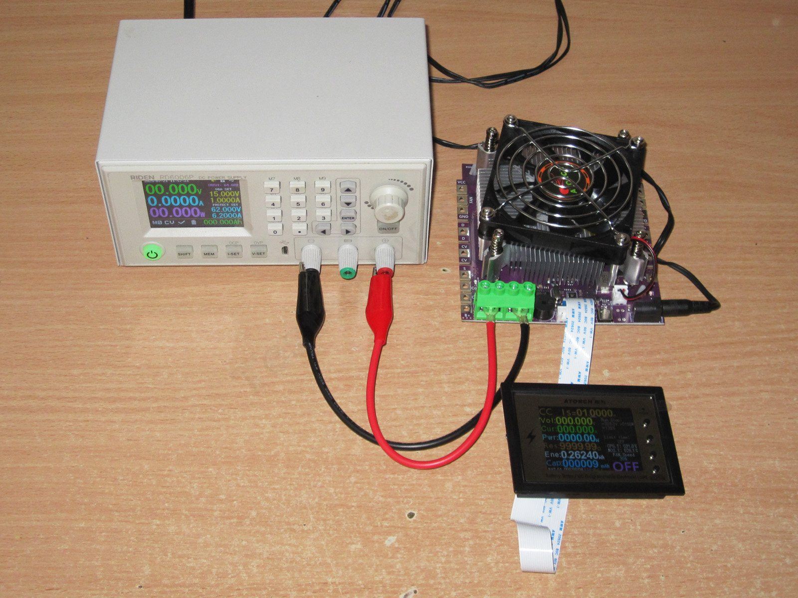
I’ll cover the hardware a little later. For now, here are some quick tests. They’re only meant to check the calibration, since you can adjust it if necessary.
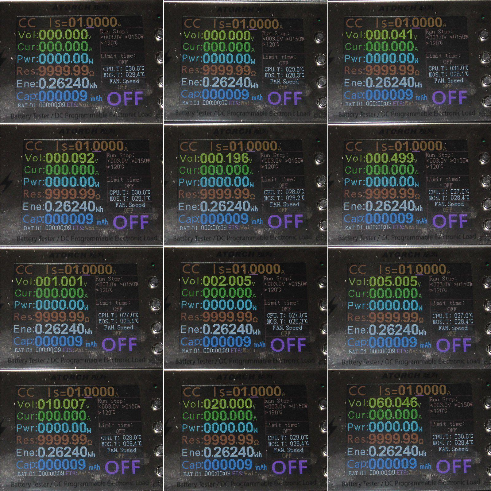
First, voltage measurements. I set the power supply voltage from 10 mV to 60 V using the 1-2-5 sequence, i.e. 10, 20, 50, 100, 200 mV, and so on. The exception is the maximum of 60 V; measuring above that is very inconvenient for me, and I rarely need to anyway.
The load didn't register 10 or 20 mV. The lowest it could measure was 30 mV; at 50 mV it showed 41, and at 100 mV it showed 92, which is pretty good.
Up to 20 V, the accuracy is almost perfect. Even at 60 V, I'd say it's more than adequate for a device like this.
Current testing was done in several stages. To start with, I used a power supply based on the RD6012P, since I was checking it with a multimeter that tops out at 10 A.
The minimum current you can set on the load is 5 mA. In practice, it fluctuated between 5 and 9 mA, so this setting can be considered unusable. This test was done without any additional modules; with them, things will be even worse, but more on that later.
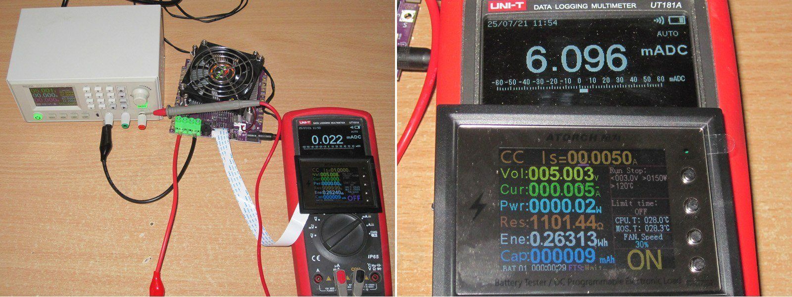
After that, I set the current using the same sequence: 1, 2, 5. At 10 mA, things looked better: the fluctuations decreased, though they were still fairly large.
I'd say the load starts regulating current properly somewhere above 20–50 mA. At 20 mA, it read 20–24; at 50 mA, it read 52–53 mA.
Overall, I consider the accuracy acceptable so far, at least in the range shown, up to 5 A.

The main unit can handle currents up to 30 A on its own. That's a small but welcome improvement, although, to be fair, the old DL24 could do that too—after a little modification.
That's why I continued testing here with a power supply based on the RD6030.
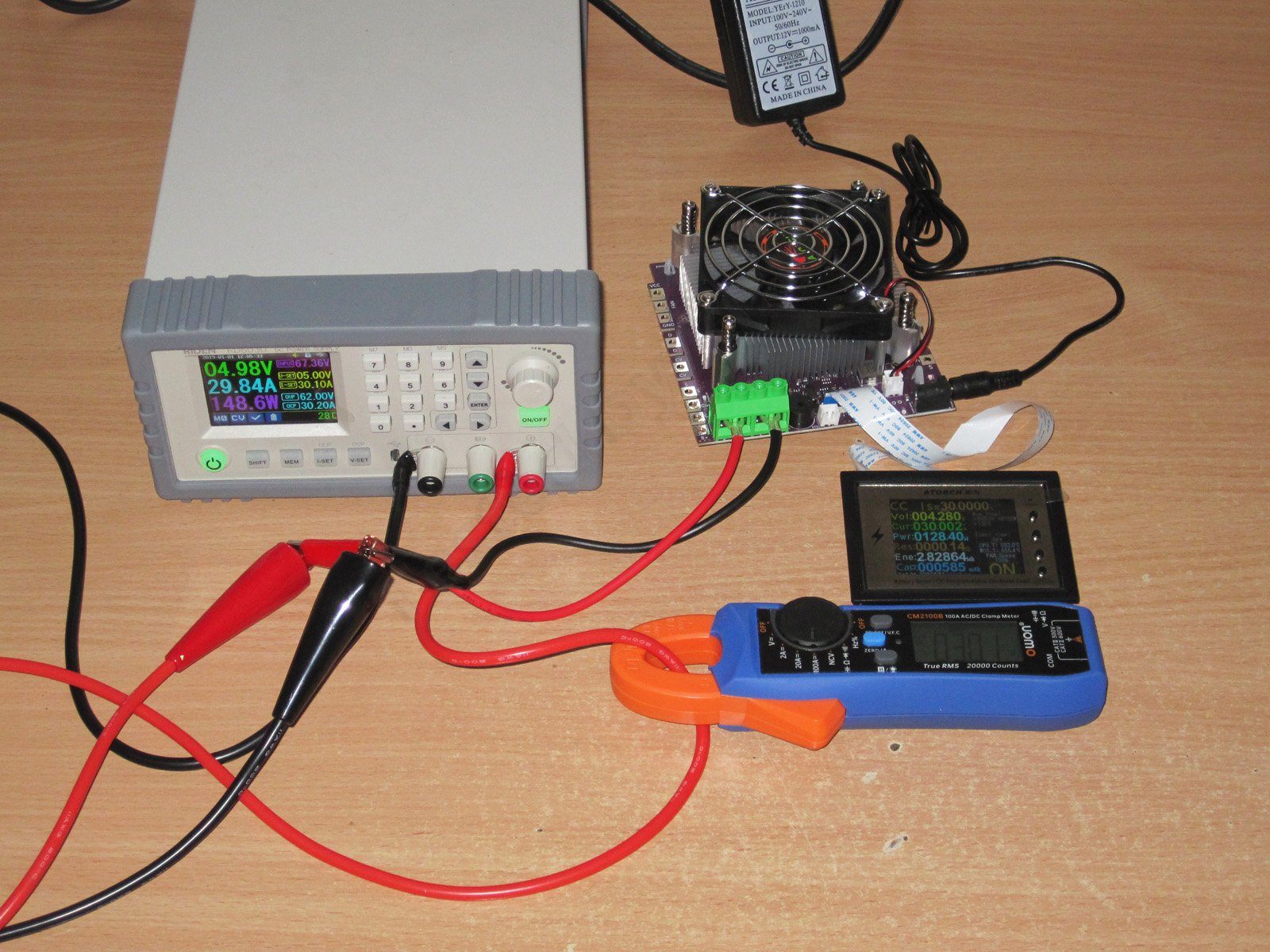
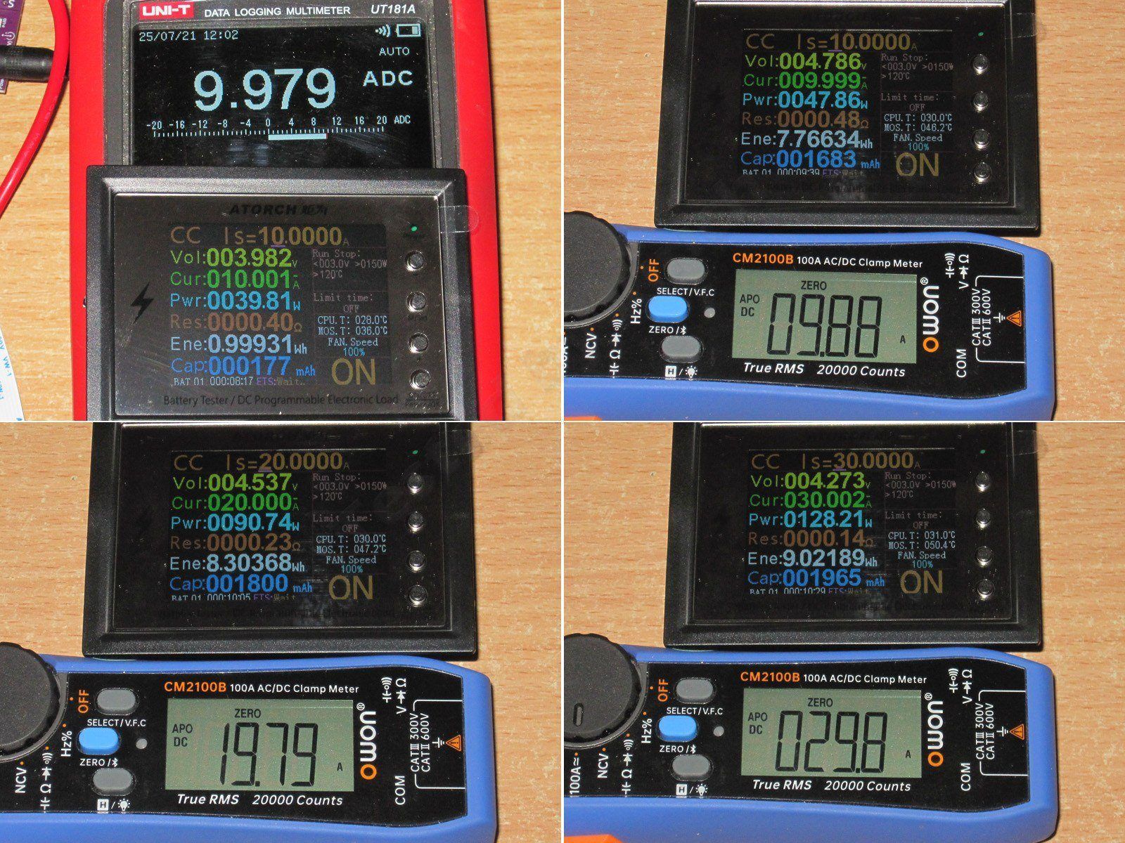
The first photo was taken while I was still testing with the RD6012P and measuring by direct contact; after that, I switched to the RD6030 and used the clamp meter.
By the way, I noticed that the clamp meter readings can fluctuate slightly depending on how firmly it's clamped, but I think the difference is negligible.
So, although the current reading is a little low here, the accuracy is fine by me, especially since, as I mentioned, it can be calibrated.
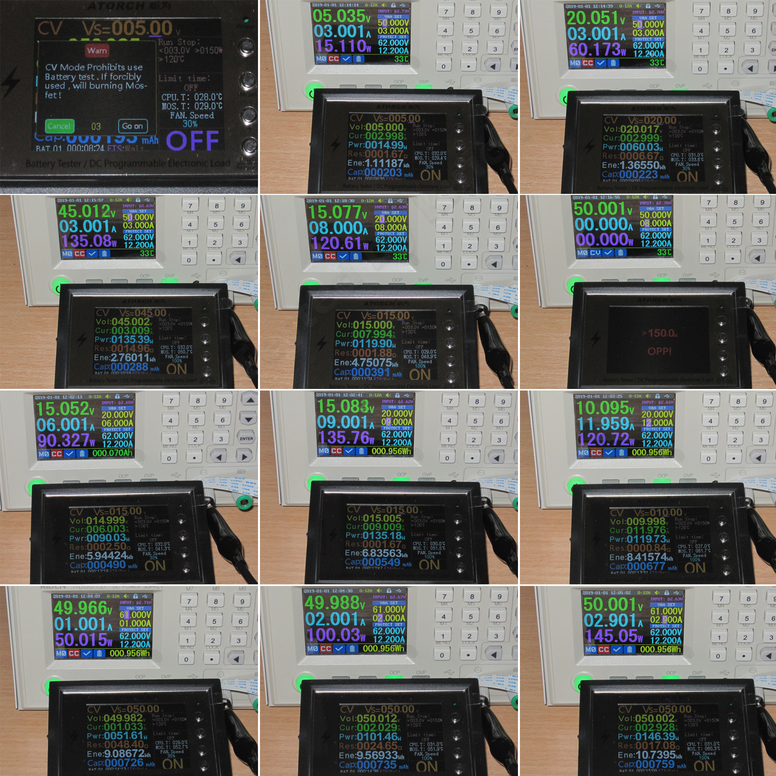
CV mode. Now it's not just me reminding you that this mode must not be used to test batteries—the load itself warns you, too. It's very easy to burn it out when testing batteries in this mode.
Overall, I have no complaints here. The mode is essentially hardware-based. I wouldn't call it fast, but it works very reliably.
The only issue was when I tried setting it to 15 V right away, with an input of 50 V and the CC current set to 8 A on the bench power supply. It almost immediately went into protection. I lowered the voltage to 20 V, and it worked correctly. Sorry, photos 5 and 6 are swapped.
But in principle, the load going into protection isn't always a bad thing, even though this happened at a power level of just 120 W.
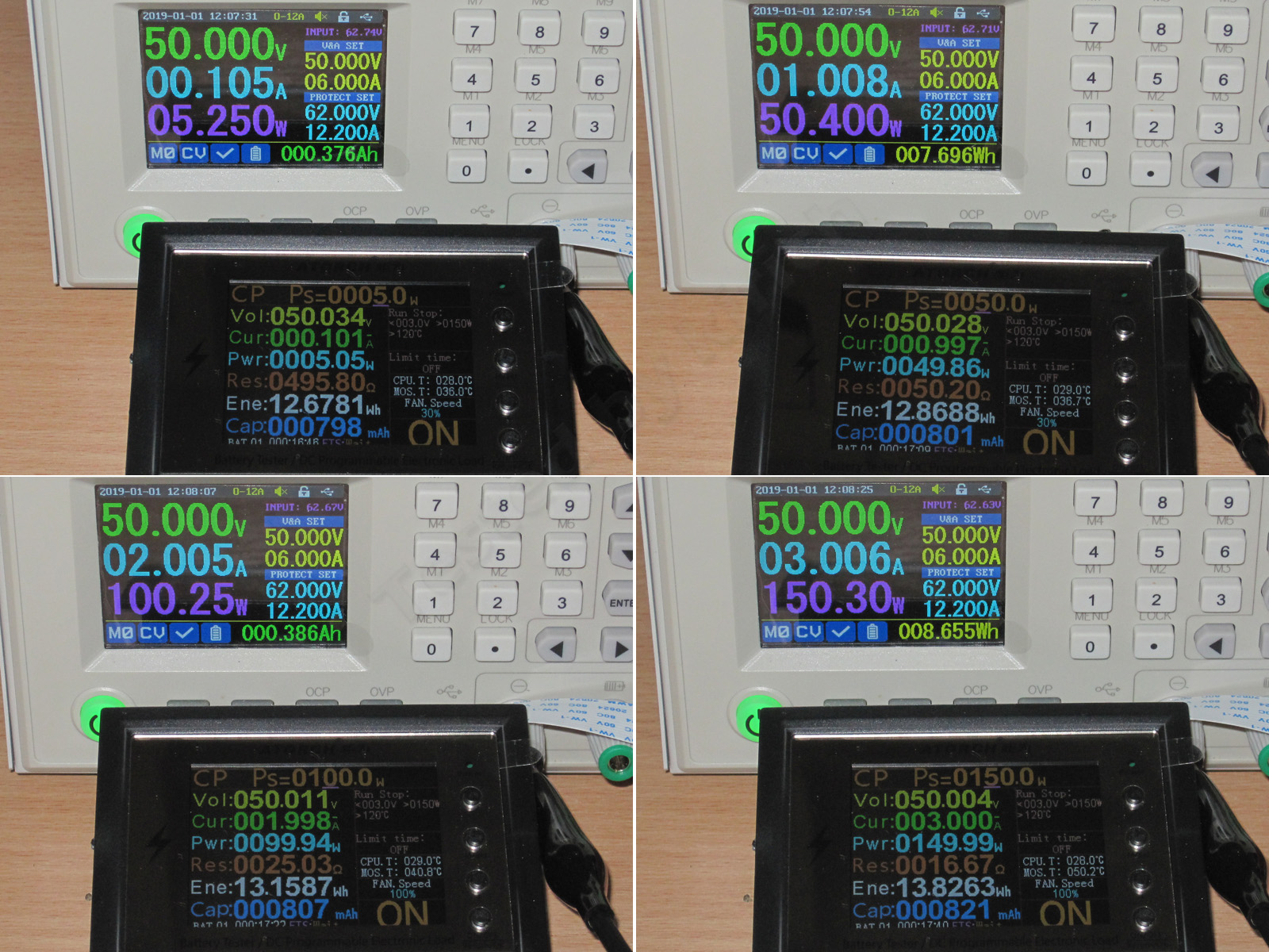
CP mode is software-based, but it works just as well and can sometimes be useful for testing batteries.
Now for the new modes.
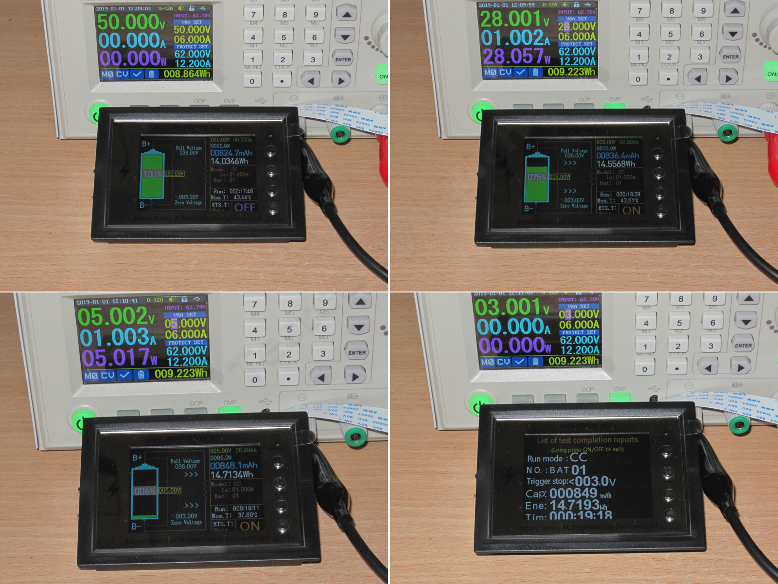
First, battery test mode. The default settings were 36 V for a fully charged battery and 3 V for a fully discharged one. Obviously, that's nonsense, but it doesn't matter for this test.
I applied 50 V and turned it on. The load current was 1 A. I gradually lowered the voltage to simulate the battery discharging. When it reached 3 V, the load stopped the discharge and displayed the results. This might be useful to someone, but for now I find the classic mode more convenient.
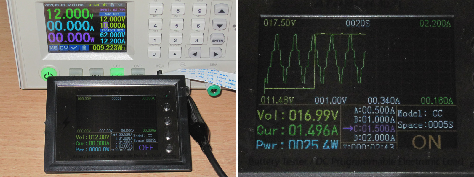
Dynamic test mode.
You can set up a program with four configurable steps, specifying the load current and the duration of each step. The same duration applies to all steps, with a minimum of 5 seconds. As I understand it, this mode only supports CC, but that's all you need here.
It's an interesting mode, but personally, 5 seconds isn't useful to me. It would be nice if you could set a shorter step duration.
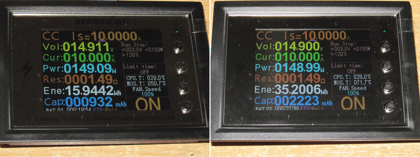
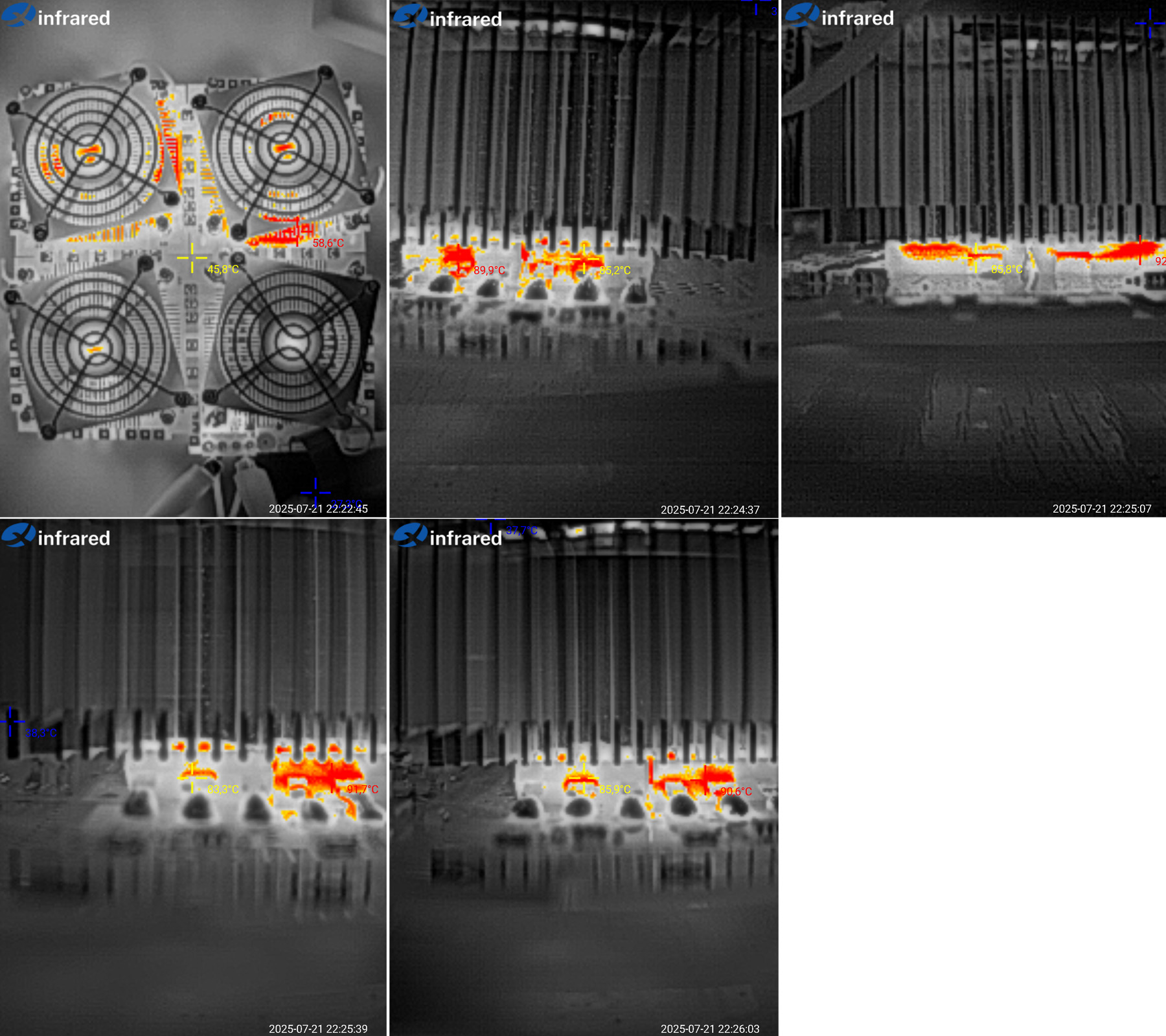
I did a quick test of the main module to see how hot it gets.
The voltage was 15 V and the current was 10 A, so the power was about 150 W. I didn't run it for long because the temperature stabilized quickly.
The temperature sensor reading was around 71–72 degrees.
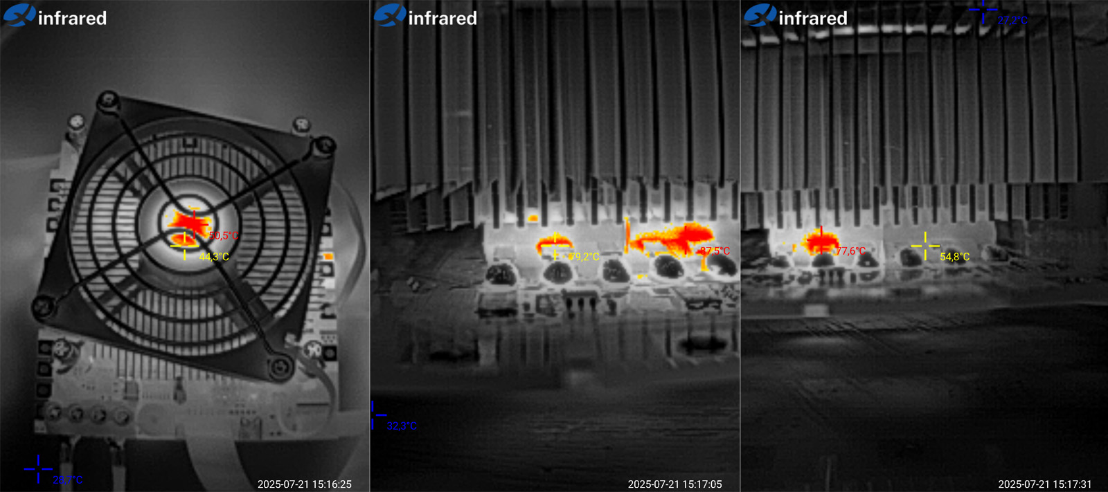
In reality, we have:
1. The right-hand side: 80 and 88 degrees. Presumably, the sensor is mounted on the transistor on the left. But there's a caveat: the sensor reads 71, while the thermal camera shows the temperature near the lead, i.e. at the hottest spot. The case temperature was closer to the reading from the temperature sensor.
2. Left side: 77.6 and 55 degrees. I’ll explain why there’s such a difference later, during disassembly.
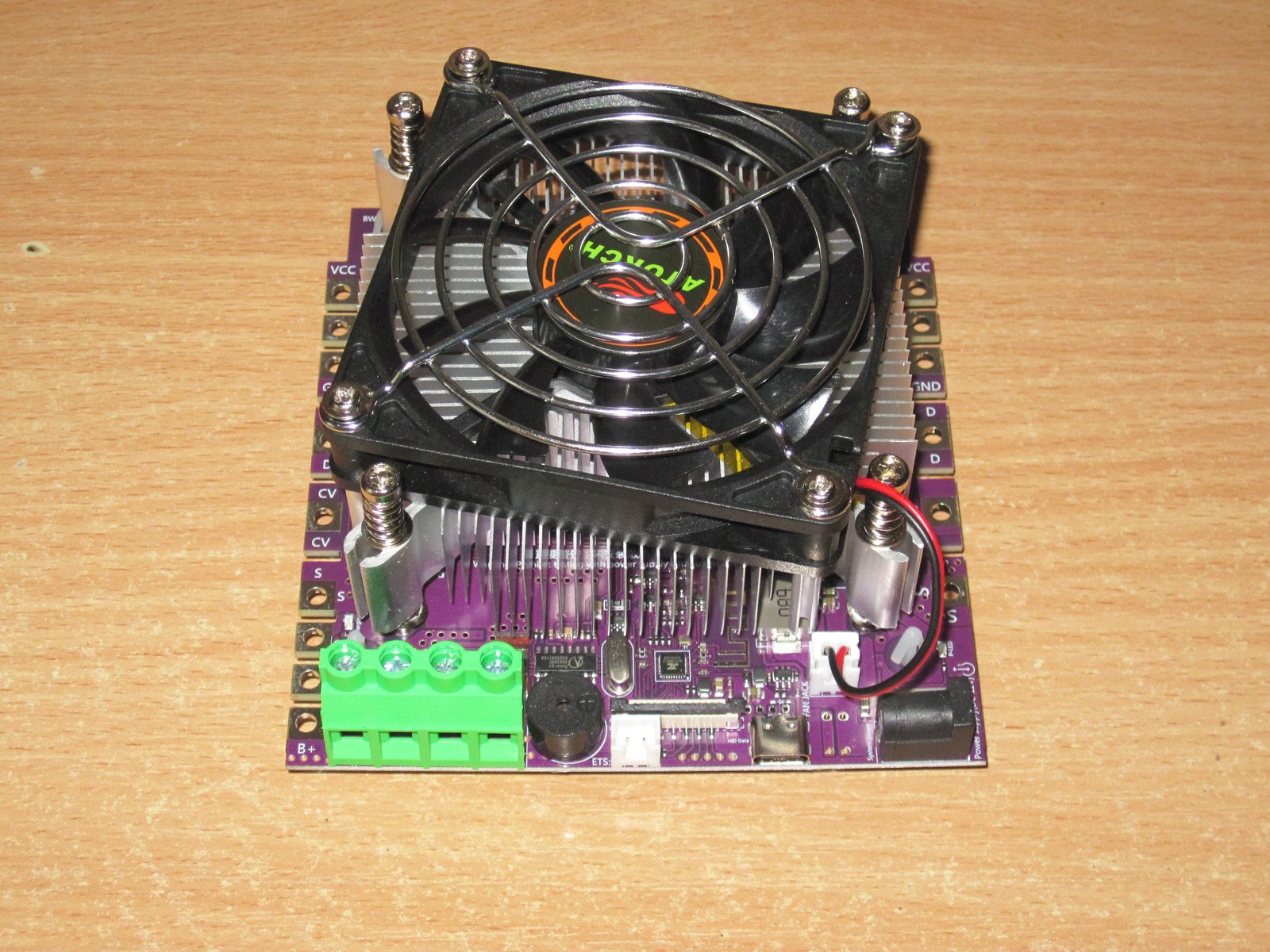
Let’s take a short break from the tests and look more closely at the circuit boards. I need to connect all these modules together anyway.
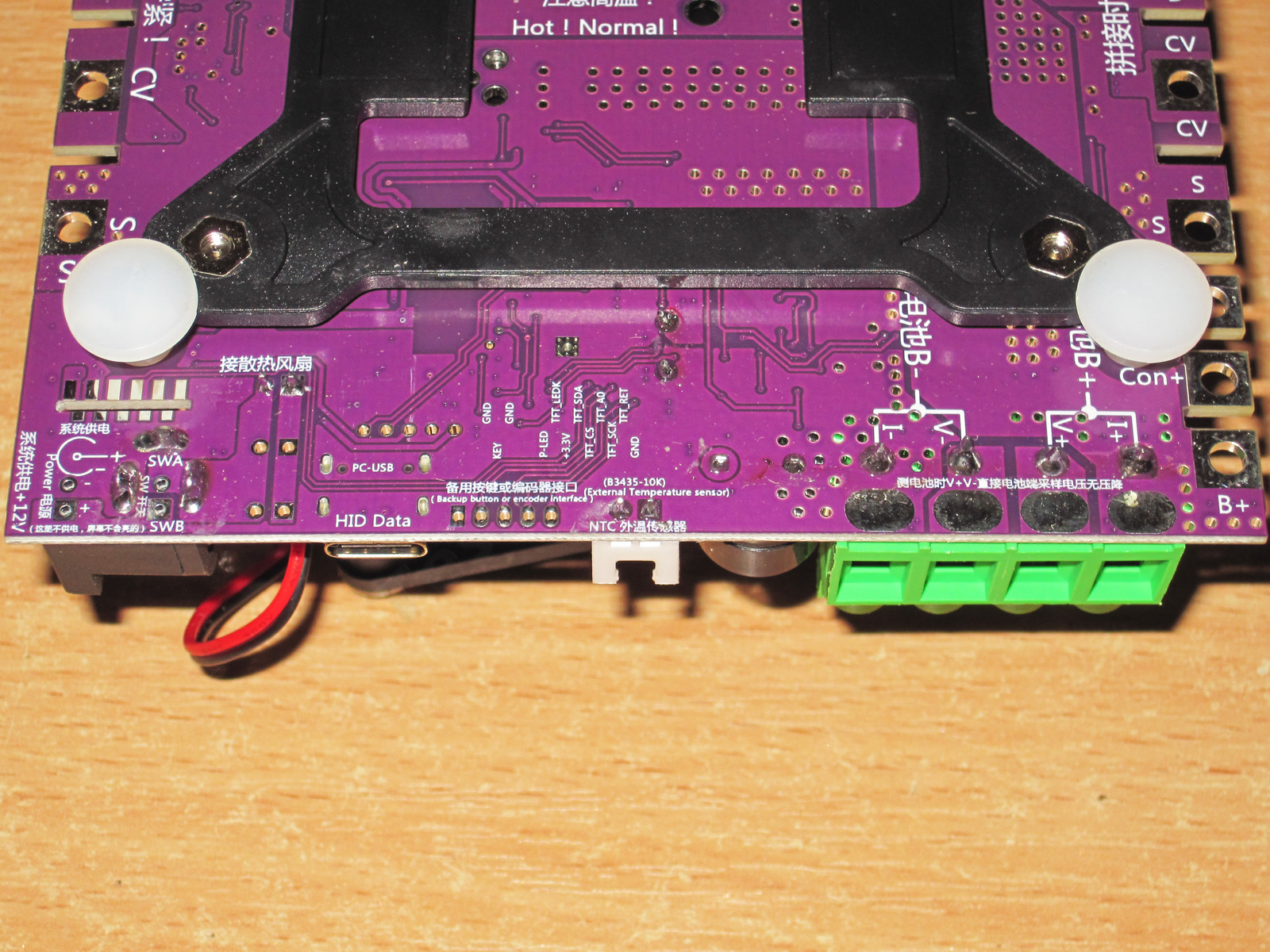
As I mentioned, the main board contains both the power section and the measurement circuitry with the control controller.
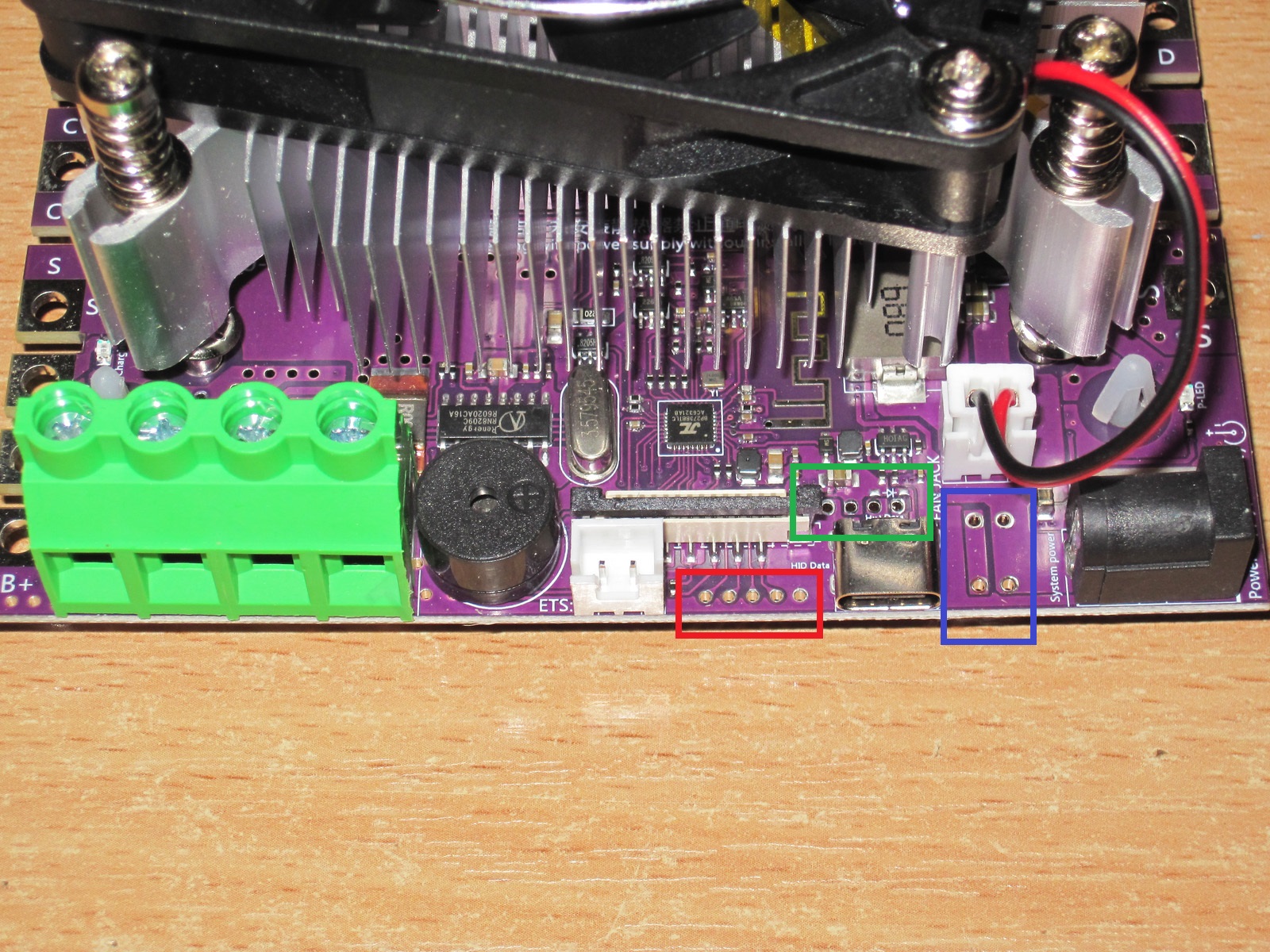
The board has both connectors and footprints for installing them. Here’s what each one is for:
1. The large terminal block on the left carries the power and measurement inputs, just like on the other electronic loads from this manufacturer.
2. To its right is a two-pin terminal block for connecting an external temperature sensor.
3. The display connector is just above it.
4. To the right of the display connector are the USB connection pads (highlighted in green). The 3.3 V and 12 V lines are also brought out there, so don’t connect anything unless you know what you’re doing. From left to right: 12 V, ground, 3.3 V, D-, D+.
5. The USB connector is below. That’s a big plus, since using a cable is often more convenient than Bluetooth.
6. Below that are the button and encoder connection pads (highlighted in red): on/off, M, -, +, GND.
7. The fan connector is to the right. Below it are footprints for two more connectors, which are wired to the fan connector. I’ll get ahead of myself and say that I’d recommend soldering a capacitor there, something like 470 µF, 16 V, with its positive lead toward the board’s power input. The thing is, under a particular combination of unfortunate circumstances, the board can burn out the fans. I’ve already ruined two this way :(
The contacts on the underside are partially labeled, but only in general terms, with no pinout. The temperature sensor sensitivity is listed, though; it’s typical for this manufacturer’s electronic loads and is 3435.
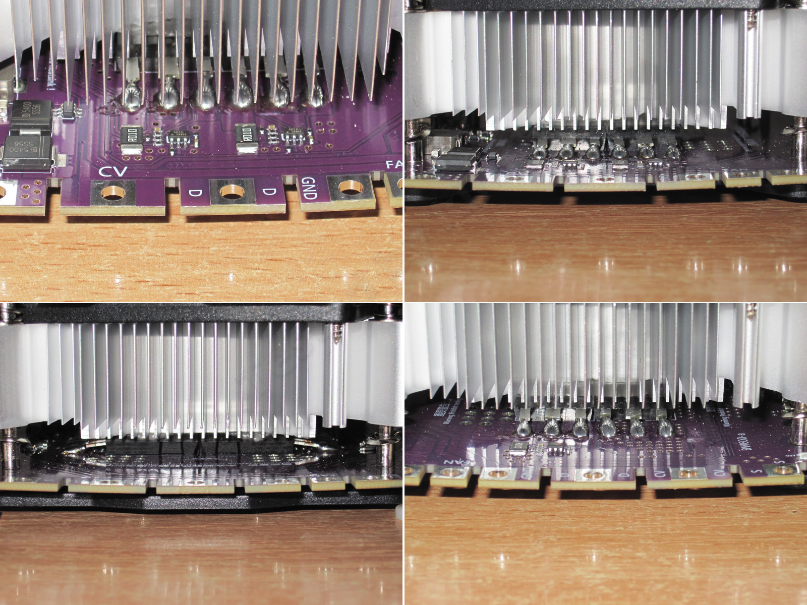
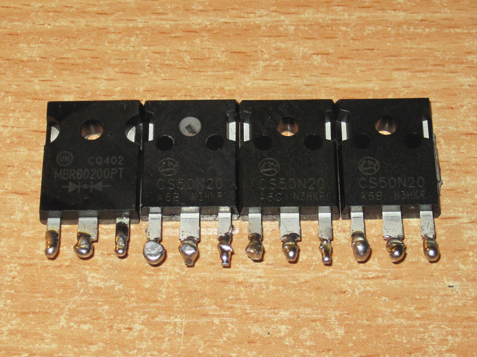
As was clear from the thermal image, four power components are installed under the heatsink. There’s a catch, though: there are only three current sensors, which suggests that one of those components isn’t a transistor, but most likely a diode.
I should point out that the board deforms quite a bit when the heatsink is clamped down—and this is a new board. I expect the deformation to get worse with use, especially at high power. That’s why I prefer the previous version with four small heatsinks, though I liked the DL24EW board even more, with its tall heatsinks.
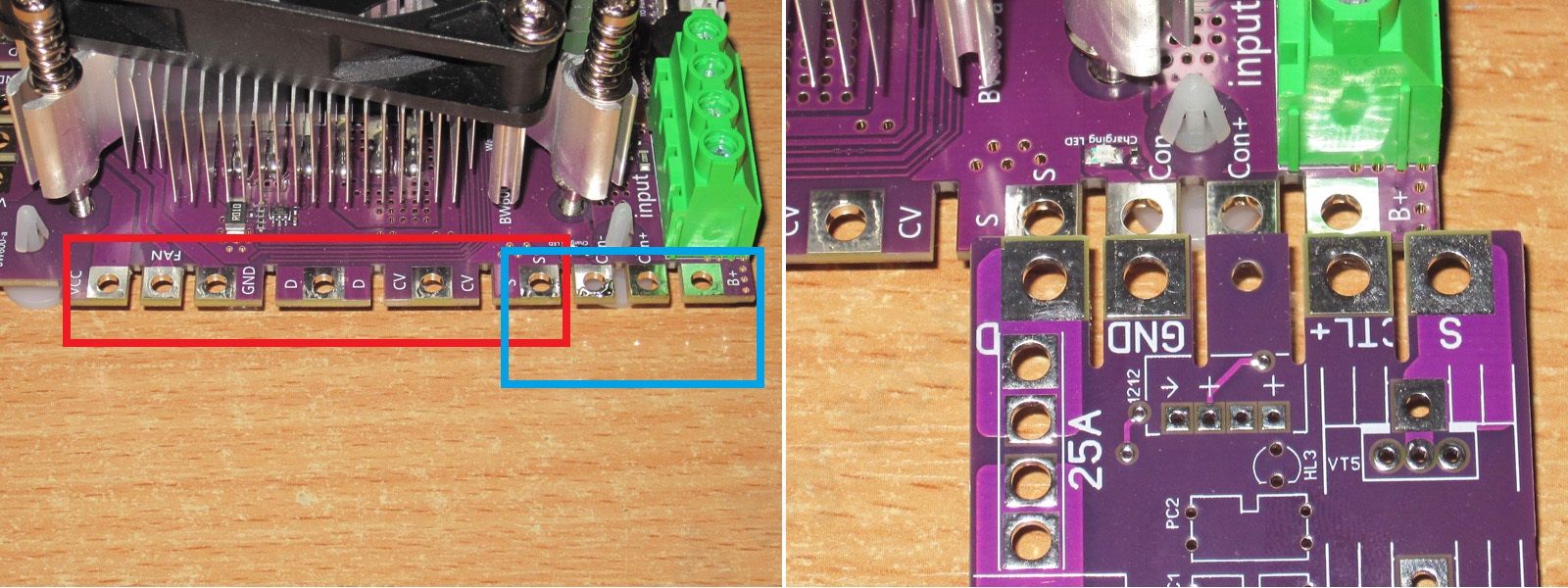
Power module connection pads are brought out on three of the four sides. The left side also has pads for connecting the charge-control board.
But there’s another catch here—actually, three.
First: on the left side, the power module pads (highlighted in red) and the switching board pads (highlighted in blue) overlap. That means you can’t install the switching board with the power module in place; it simply won’t fit. But you can always solder wires to the pads.
Second: the switching board pad layout differs from that of the old boards and the boards I make. However, the pad order itself hasn’t changed (the D and S labels on my board are swapped, so ignore them). The old board used pads 1, 2, 4, and 5; the new one has four pads, but the signal order is the same. So you can’t install a previous-generation board directly, but you can always solder wires to the pads.
Third: most diagrams for installing power modules show the left module (on the switching-board side) being installed first, with the others added above or to the right. There’s a reason for that. If you install modules on the right, most of the load current will flow through the entire main module board. The more power modules you install on the right or above, the greater the share of current that will flow through the whole board. If the power modules are installed on the left, the current takes the shortest path, since the input terminal block and shunt are also on the left.
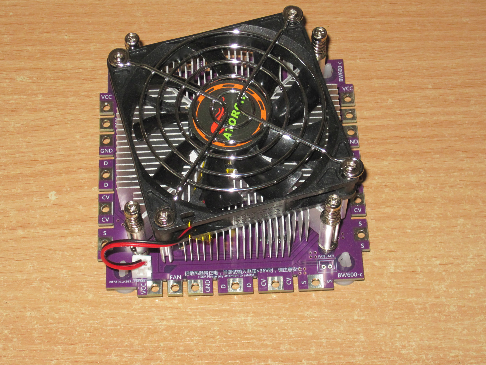
The power module has changed too, and it isn’t compatible with the previous-generation modules, as noted on the product page. So if you buy the old 24MP, you need to buy the old modules as well; the new BW600 requires the new modules.
There are now four balancing circuits, and accordingly, four transistors.
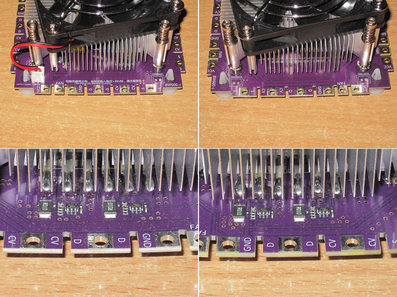
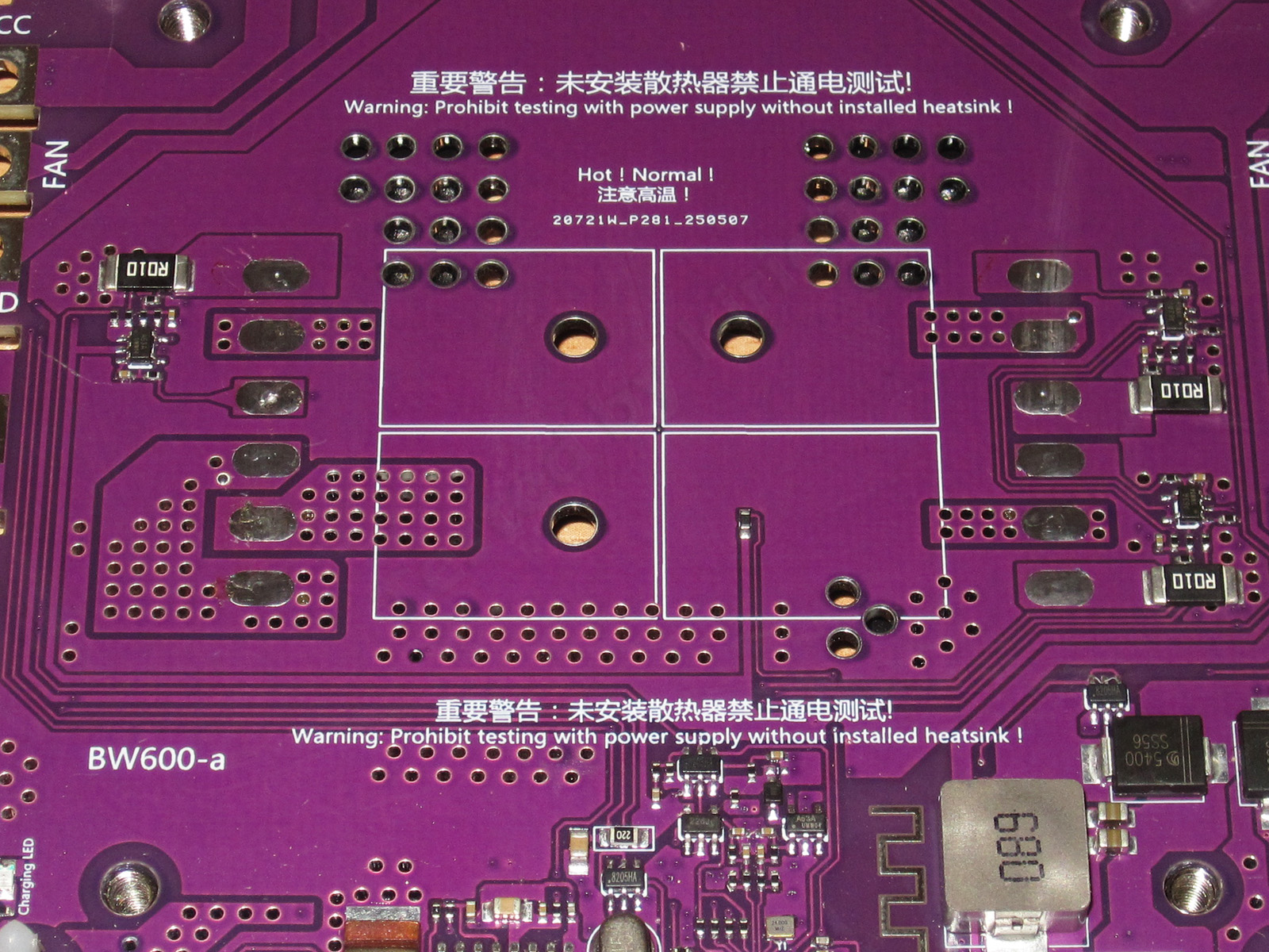
While inspecting the board, I noticed three holes on the back near the power transistors, even though there are clearly four transistors.
It’s the same on both the main board and the power boards. I’ll explain why later, but to get ahead of myself: on the main module, the temperature sensor is on the transistor that doesn’t have a hole in the board.
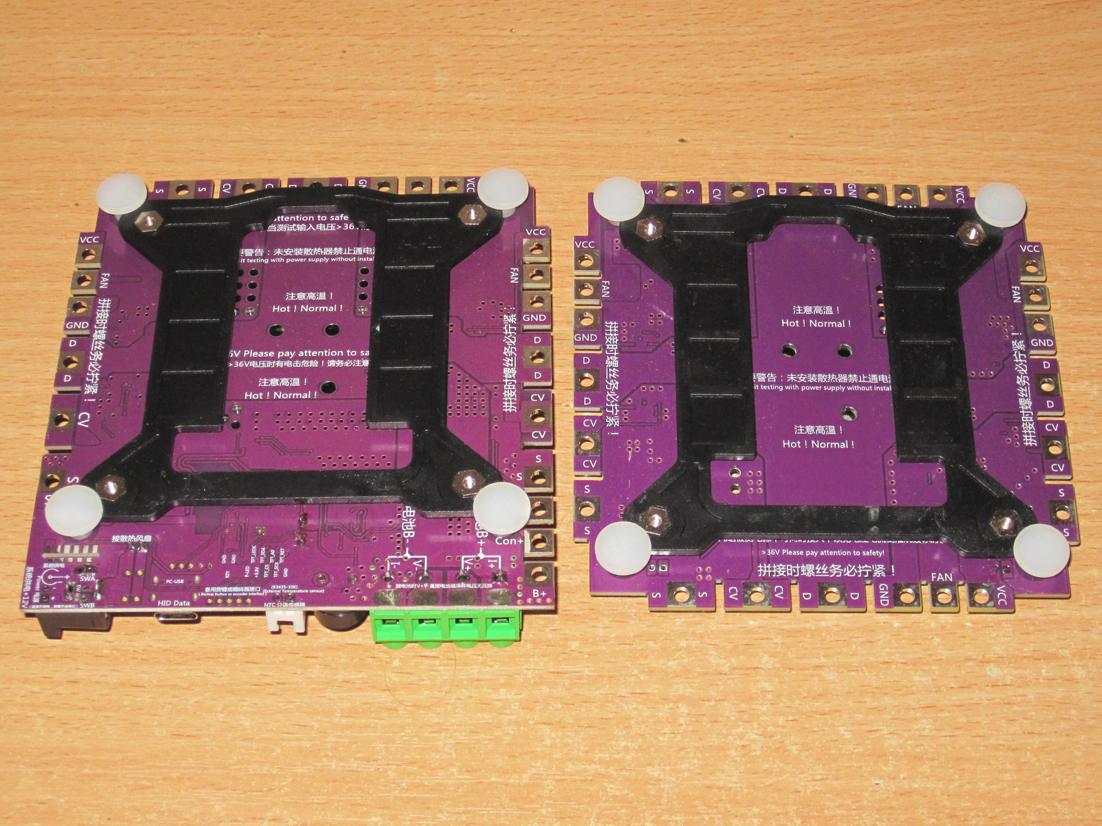
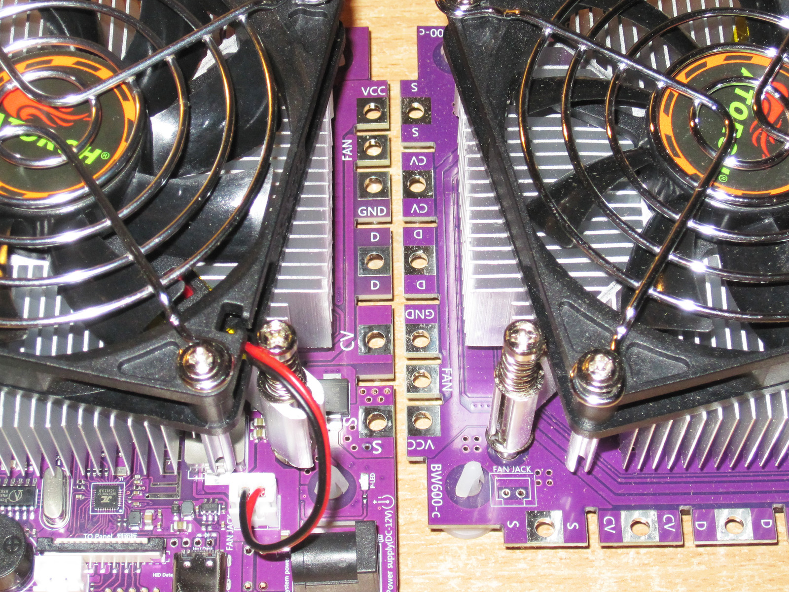
Be careful when connecting the power boards, because depending on their orientation, the contacts may not line up, i.e. It's best to lay the boards out on the table first, making sure ALL the contacts line up with their labels, and only then assemble them. After assembly, check everything once more.
There are six contacts here: the transistors' Drain and Source, Ground, Power, Control Voltage, and Fan Power.
And I have to say, the extra contact—or, more precisely, separating the power ground from the signal ground—is a very good idea.
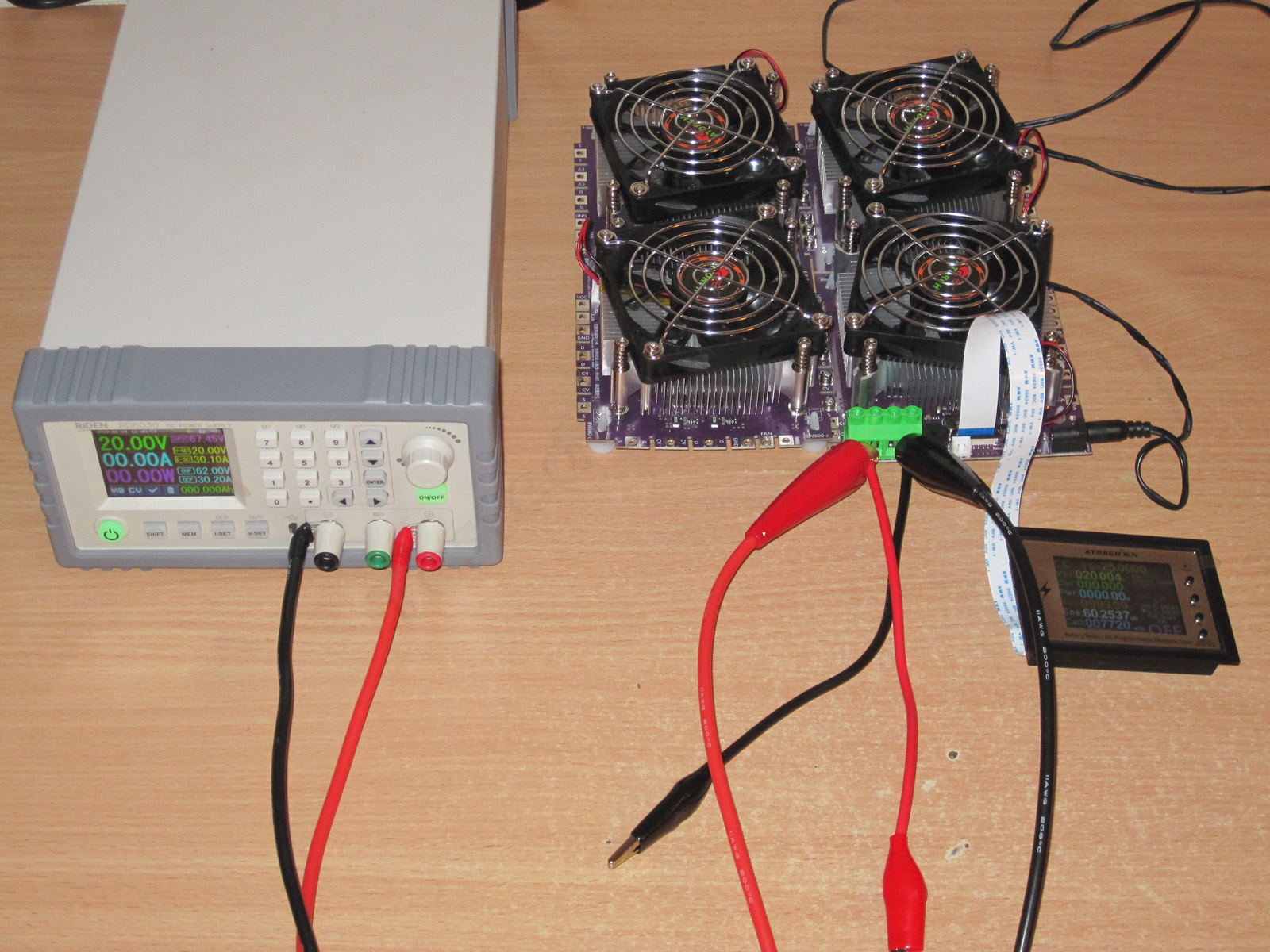
Anyway, I put together a combination of the main board and three modules. I tried to figure out why one of the fans is mounted differently, but couldn't work it out. It looks like its heatsink is upside down :)
Next, go into the settings and select the configuration you've assembled. I wanted to connect three more power modules, but couldn't find an option for one power module plus six additional ones.
But then I realized you can connect pretty much any number of modules. Here's how:
1. Connect all the modules you have—for example, let's say you have 9.
2. The settings only offer the nearest options, +7 and +11. Choose the higher one, +11.
3. Since we have 1+9 modules (the main one plus the additional ones), and each module is rated for 150 W, that's 10 modules in total, including the main one: 10 × 150 = 1500.
4. Go to the power limit settings and set it to 1500 W or less.
5. That's it: we have a load with 1+9 modules and a power rating of 1500 W, even though that configuration isn't listed in the settings.
Honestly, I think it would have been simpler to add a setting where you just enter the number of modules, from 1 to 19, instead of filling the menu with a bunch of options.

Since I've already hit the limits of both the base unit and the power supply when it comes to accuracy testing, I'll start by checking how the load behaves at full power, but not at full current.
I measured temperatures wherever I could reach. Basically, I checked a couple of transistors in each module.
The temperatures varied, but averaged around 90 degrees, which is perfectly normal.
Let me explain. A transistor operating in linear mode is more complicated than one operating as a switch, and several factors have a major effect on reliability: temperature, power, and voltage.
The higher the temperature, the lower the transistor's allowable power. So 100 degrees on the case while dissipating 35 W is not at all the same as 100 degrees while dissipating 100 W. That's why 90 degrees and 37 W at the case is more than fine.
Also, the higher the current and the lower the voltage, the easier it is for the transistor to operate. So, for example, 10 V and 50 A is easier on the load than 50 V and 10 A.
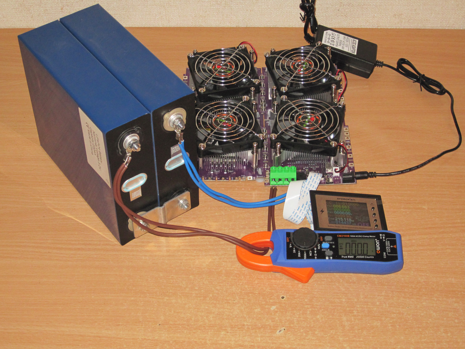
Of course, I wanted to test the load at full current. To do that, I had to use half of a 12 V battery; I couldn't use the whole battery pack, since that would have pushed the power above 600 W.
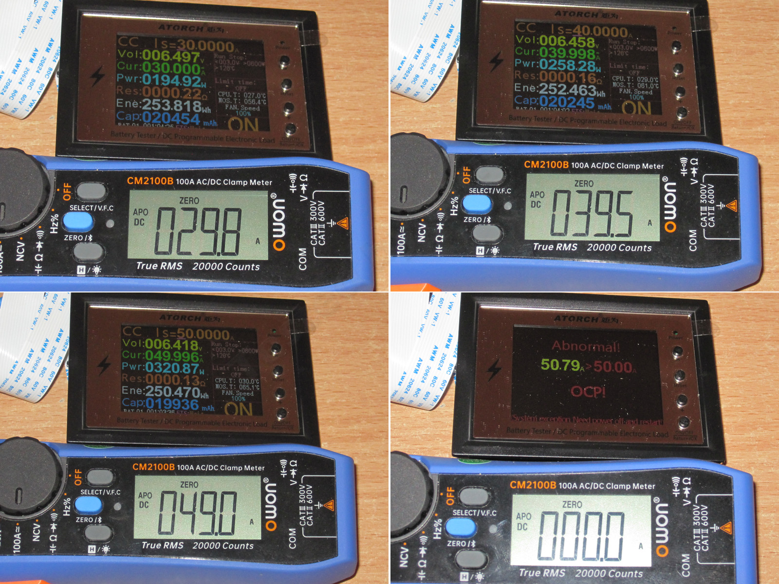
The load reads the current a little low. I think it would be worth tweaking it slightly in the calibration menu, but what concerned me more was that when I tried to run it at maximum current, the load would sometimes trip with an overcurrent error. I think the more modules there are, the more often this will happen. I'll explain later why I think so.
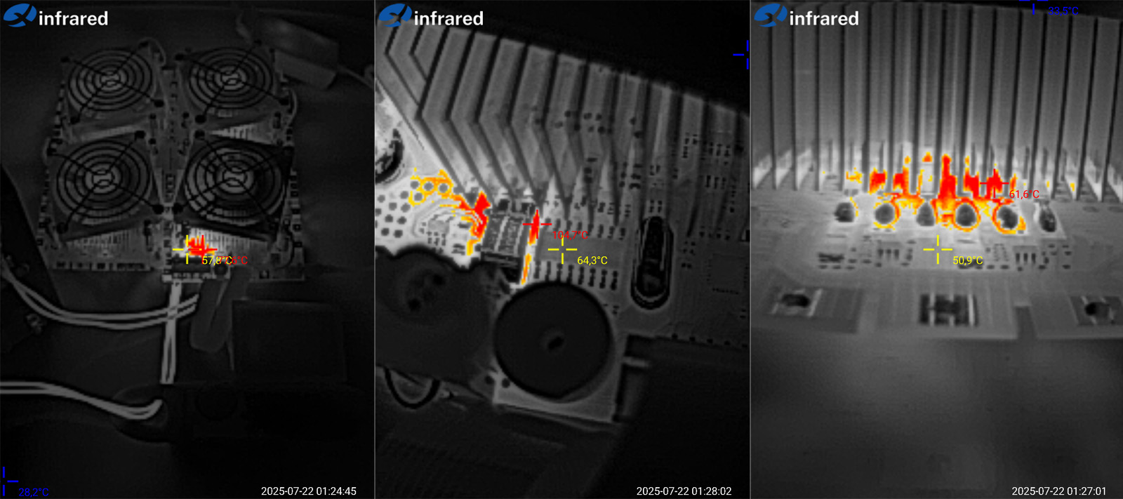
In this mode, the temperature is of course noticeably lower, and the hottest component is the current-sense shunt.
Before moving on to the hardware and circuit design details, I'll run one more test. Though in this case it's more of a demonstration that the charge control function works.
For this, I assembled several little boards. I only needed one, of course, but it was more convenient to put several together at once.
I connected them with wires, and as I mentioned earlier, the contact order is the same as on the new version.
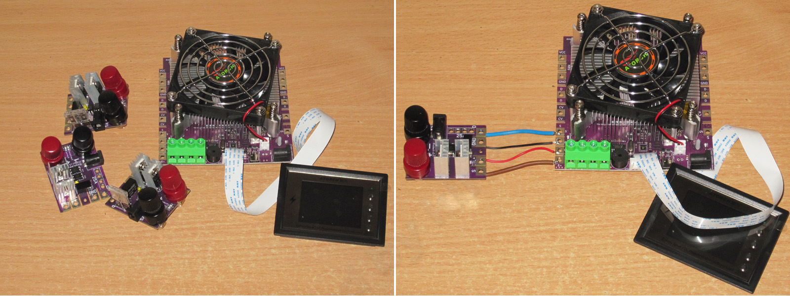
Next, I connected a power supply as the charger. It's best to use the shortest wires possible here, but I didn't bother since this is just a demonstration.
A few notes about this mode.
The load doesn't measure the charging current at all. Its only function is to connect your charger (preferably a bench power supply) to the battery when it needs charging, and disconnect it when the battery voltage exceeds the set limit or the current in the battery circuit drops below the set limit.
In other words, you have two parameters that determine when charging ends:
Maximum battery voltage. I recommend setting it a little higher than required. For example, if the battery is 25.2 V, you could set it to 26 V. In other words, you can use this function simply as a protection.
Minimum current. This one is important: set it to 1/10 of the charging current, i.e. If the charging current is 10 A, set the cutoff current to 1 A. Once the charging current drops to that level, the load will disconnect the charger from the battery.
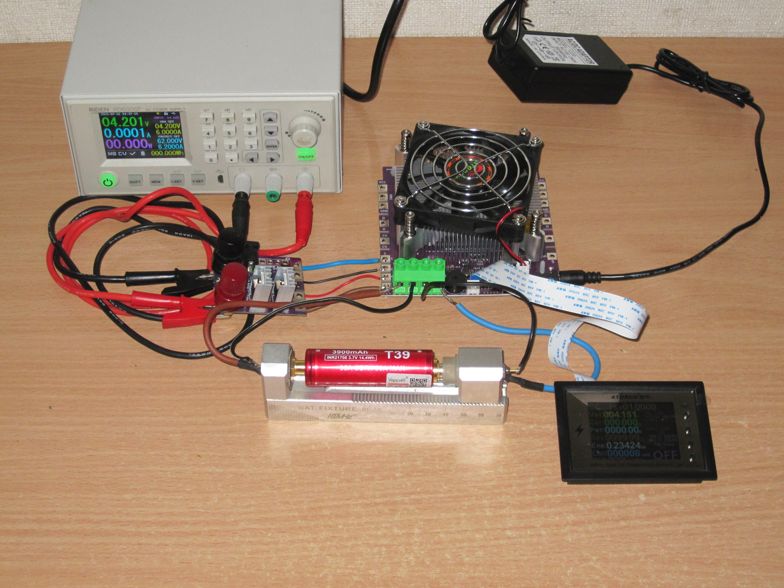
The settings in my example are a little different, because waiting for a full cycle would take far too long and get pretty tedious.
1. Set the charging voltage to 4.2 V, the charging current to 6 A, and enabled the power supply output.
2. Switched to CDC mode.
3. First, the load reminds us to connect a charger. I did that in step 1.
4. Set the discharge cutoff to 3 V and the discharge current to 15 A. Left the maximum voltage at its default of 30 V, set the charge cutoff current to 0.95 A, and left the discharge time unlimited.
5. Press Start. It asks whether we want to clear the previous data and start the test; we agree. If we had interrupted a test before this, there would most likely have been three options, the third being whether to resume the previous test.
6. That's it: the load connected the charger and started charging the battery. The current is lower because the battery was almost fully charged.
7. It notified me that the first stage was complete. The timer counts down for a minute (this can be configured), then moves on to the next stage.
8. Discharging started at 15 A. You can change the current while the test is running.
9. After this stage finishes, the timer appears again, followed by the next stage of the test.
10, 11: charging started at 6 A.
11. Once charging is complete, the load displays the timer again—though it's not clear why—and then switches to the results screen.
The whole process is fully automatic. Once you press Start, there's nothing else to do but wait for the test results.
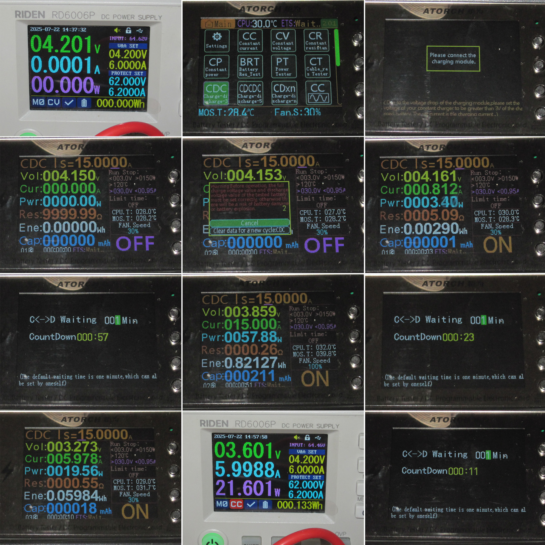
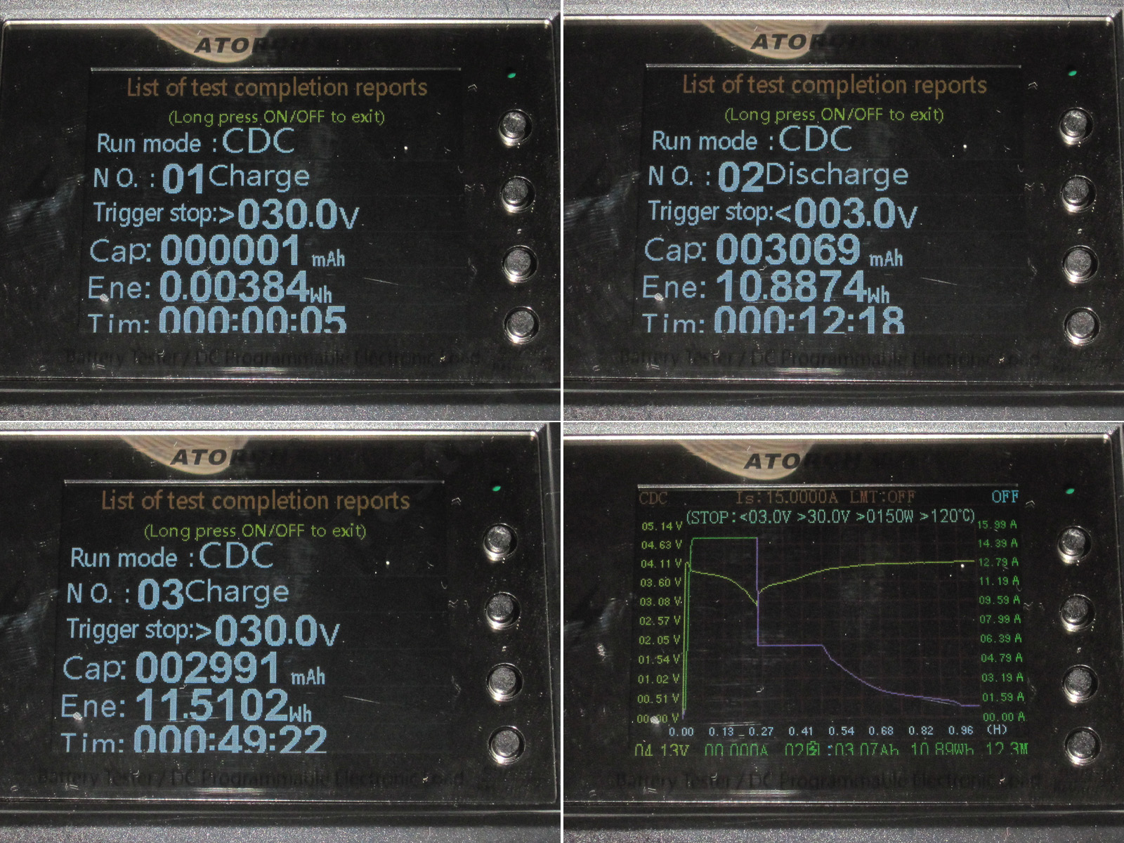
Next, it cycles through three screens showing the results for each test stage. If you select CDCDC mode, there will be five stages instead of three.
If you go back to the main menu and select the same CDC mode with a graph, it will display the graph for this test. The graph is recorded separately and stored until you clear the results or start a new test.
So, let's see how it's put together, give it credit for the useful new features, and point out the shortcomings.
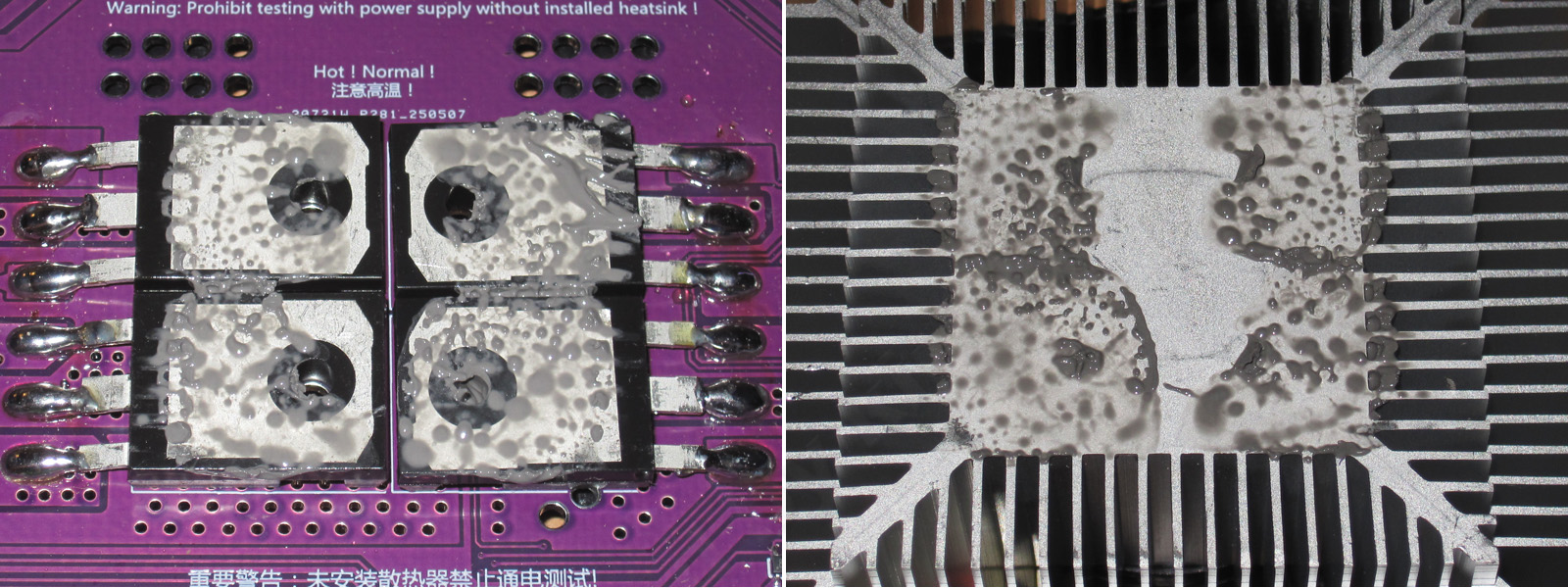
As expected, there are four TO-247 components under the heatsink, generously coated with thermal paste.
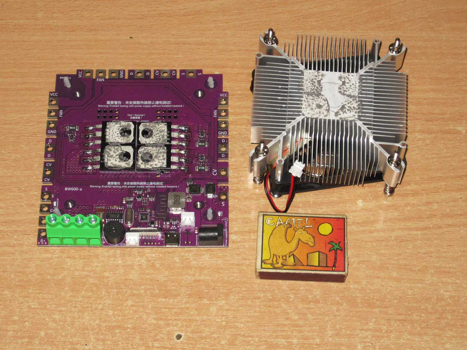
There's a decent amount of thermal paste, but it doesn't cover the entire surface of the components. I wouldn't say that's critical here, but it's definitely difficult to get all four components level under a single heatsink. Put it this way: with this heatsink mounting arrangement, there's a greater chance something will go wrong. So I recommend that everyone who buys one remove the heatsink before using it and check that everything is in order.
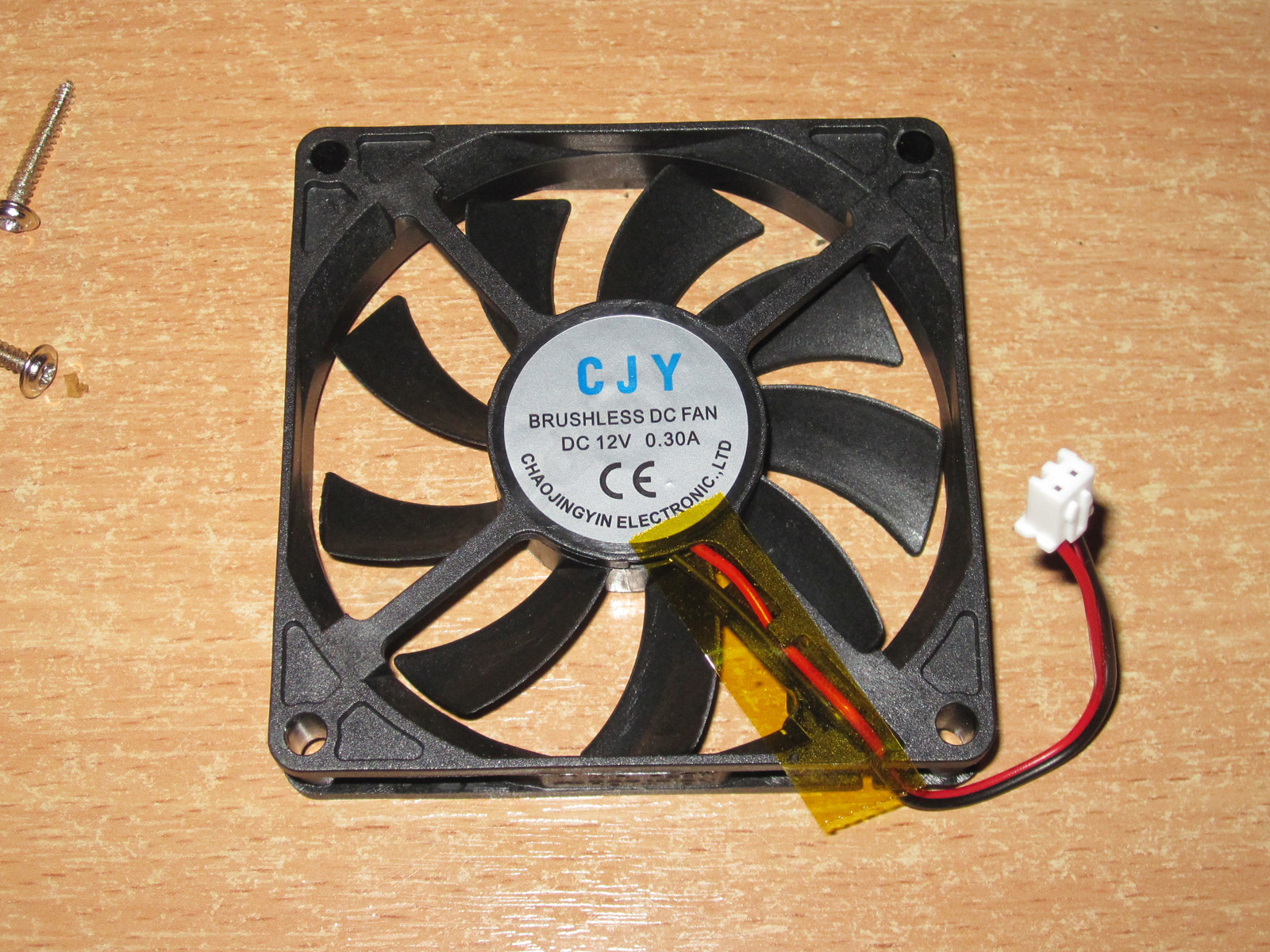
The whole assembly is cooled by a 12 V, 300 mA fan measuring 80 mm. Unlike the previous version, though, this one is thinner: 15 mm instead of 20.
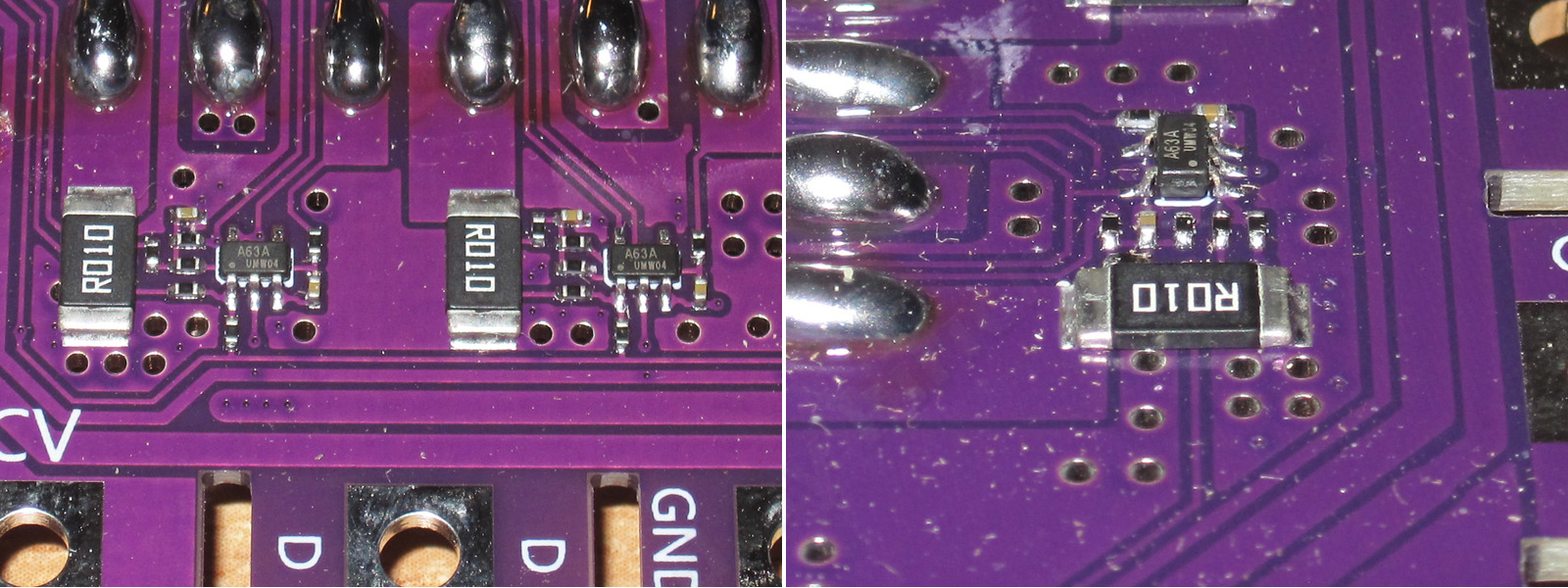
The current-balancing circuit for the transistors.
There are some obvious changes. First, the shunts are now rated at 10 mΩ instead of 220–250 mΩ as before. The shunts themselves are also quite good quality: 1206 size, typically rated for 2 W. I use similar ones myself; they're very reliable.
In the worst-case scenario, the shunts dissipate just 1 W in total. That's with one main module and a current of 30 A. In every other configuration, less current flows through the shunts, so they're comfortably overrated here.
There's a voltage divider before the op-amp that reduces the control signal by about 22 times. That's also the right approach; I've been using it for a long time, and my divider ratio is practically the same.
And here are the “brains”—though essentially, this is everything: power, control, and measurement.
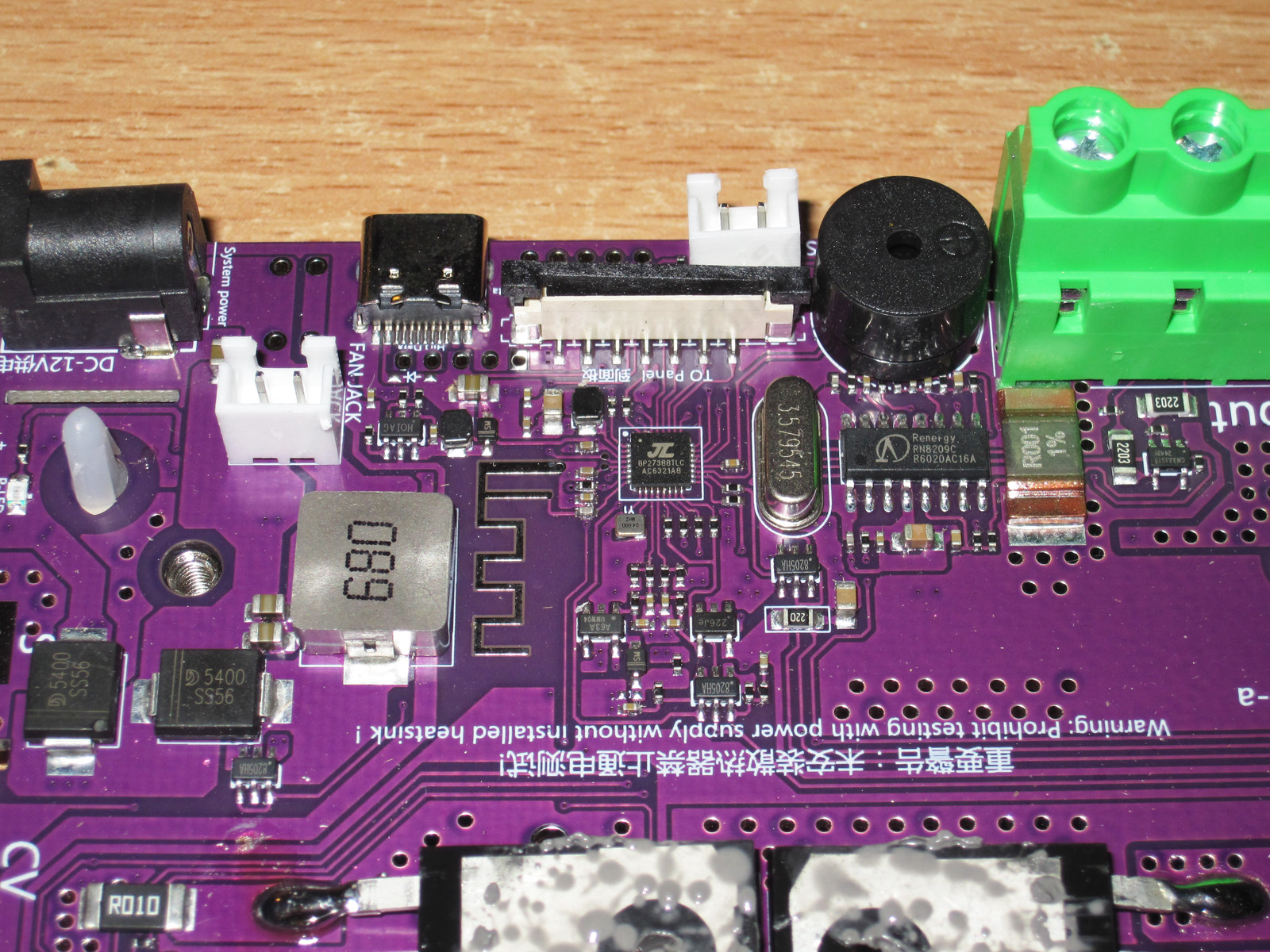
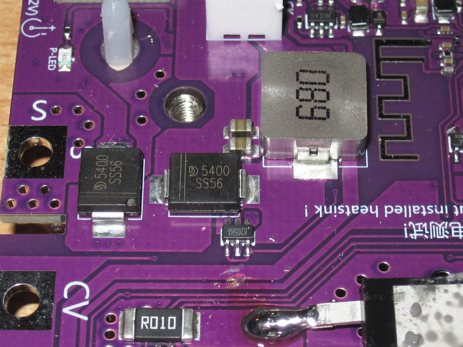
The protection and fan-control circuit.
On the left is a diode connected across the board's power input. Its job is to protect against reverse polarity, and I have to say, that's useful. I've mixed up the polarity a couple of times myself, and people sometimes come to me with the same problem.
On the right are a diode, a transistor, and an inductor. This is the fan speed control circuit, driven by the main controller. There's no feedback; it simply changes the PWM duty cycle.
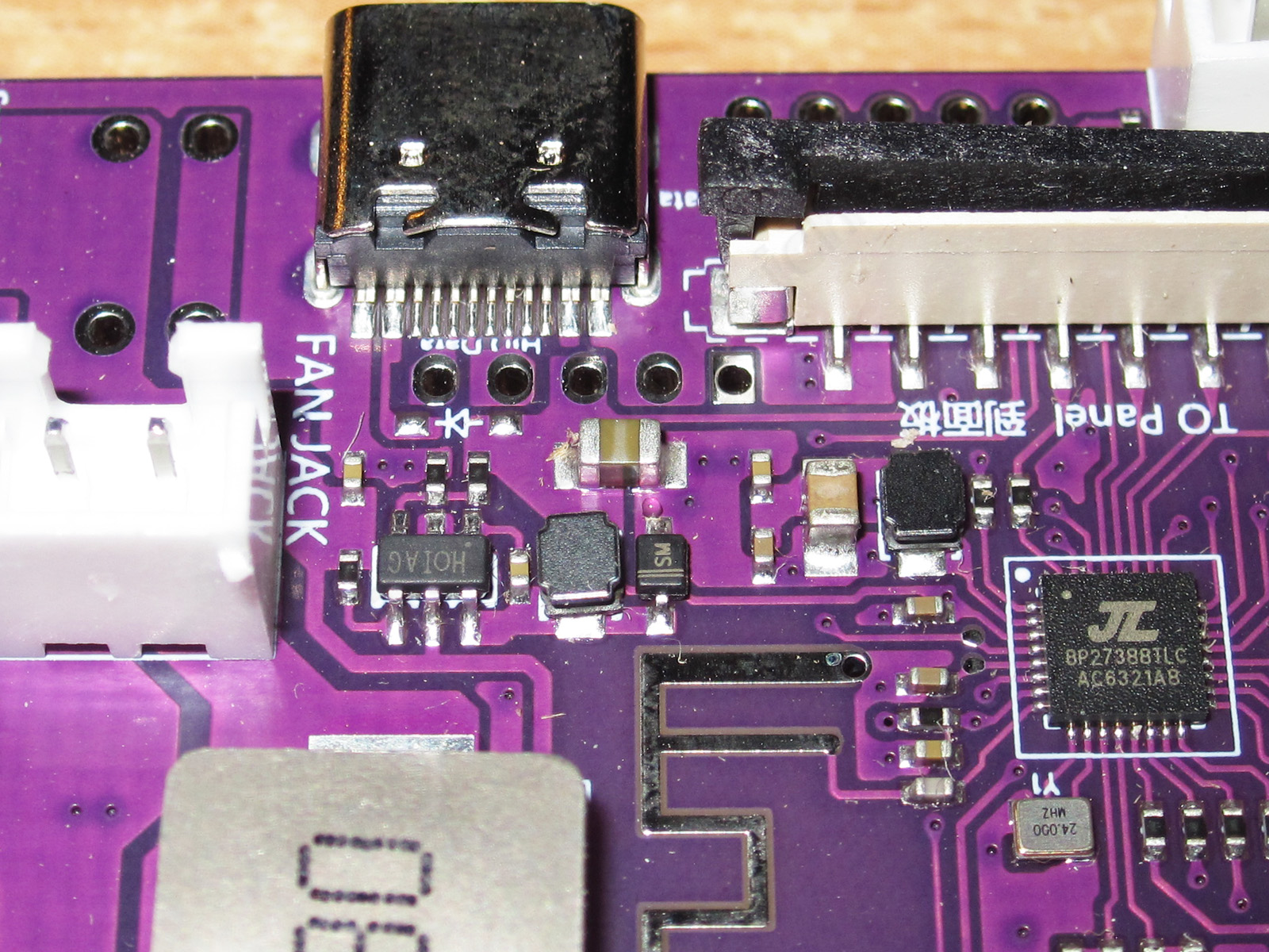
By the way, the fan speed control itself is nothing special. It starts at 30%, then goes to 100% if the power exceeds 100 W (which seems unnecessary to me). But there's a worse issue: the fan “wakes up” for about a minute whenever anything so much as sneezes. There it goes quiet; you just press some button and it turns back on. Why? No idea.
Yes, I don't know how many fans the board can power. Four definitely worked fine; maybe up to eight will work. I have no idea what to do with 20, but the main board definitely can't handle them, and neither can the power supply.
The 3.3 V power regulator. There's some kind of inductor on the right, too. At first I thought it was another regulator, but there's no controller nearby. The filter capacitor has 1.3 V across it. Maybe it's an external filter for some reference voltage, but that's just a guess, since I haven't studied the controller's architecture.
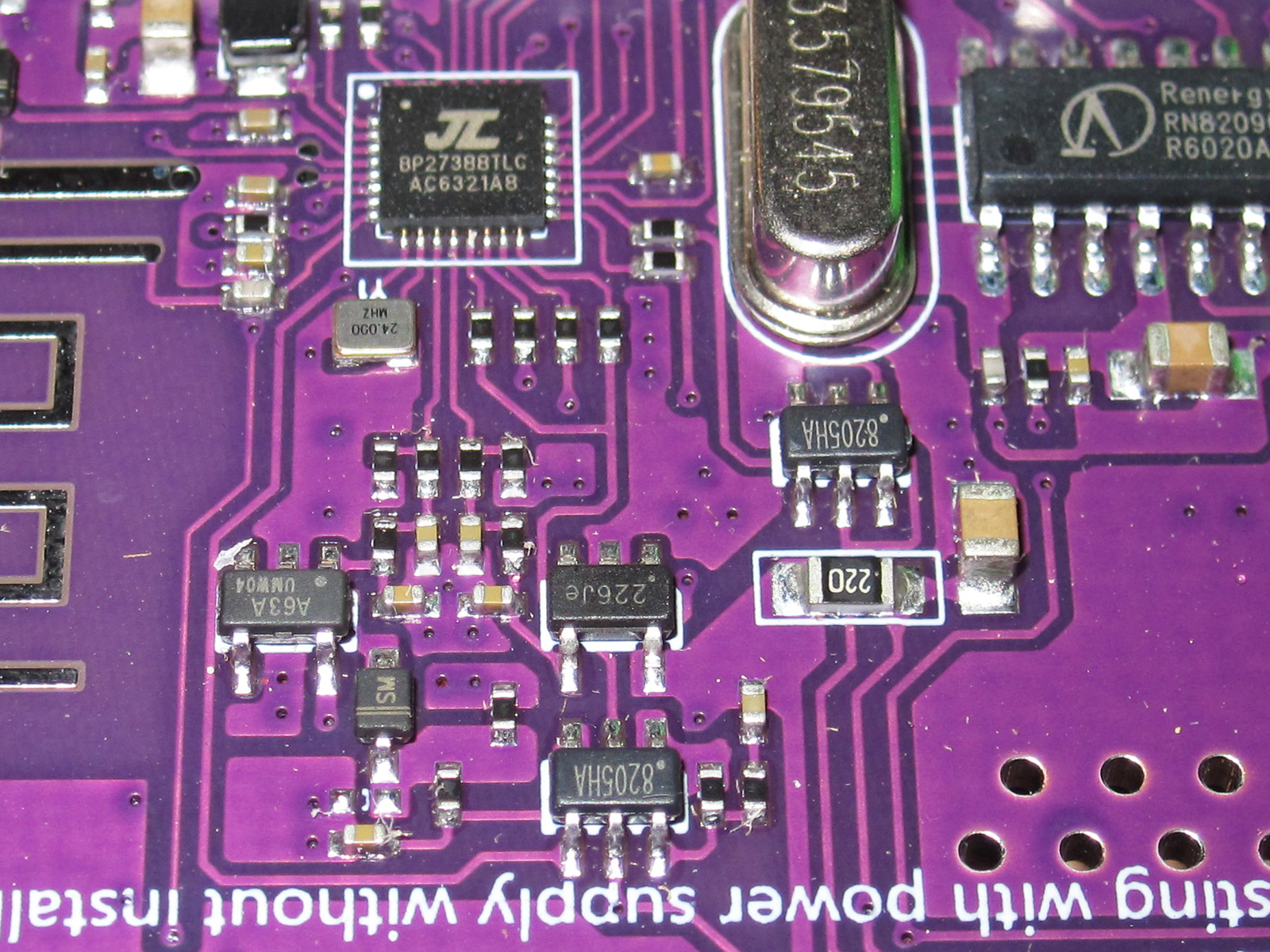
A pair of op-amps and a transistor next to a cluster of capacitors and resistors make up two PWM DACs.
Previous versions had one such DAC, whose output was switched either to the power stage input or to the CV-mode comparator op-amp. Here, they took a slightly different approach: they removed the switch and added a second DAC, but the two operate alternately.
The op-amp on the left is the buffer amplifier for the first DAC.
The op-amp on the right is the CV-mode op-amp.
The transistor just below is there to prevent the control voltage from reaching the power modules right at startup. The DL24EW had this problem, and I had to work around it in hardware, too. Here, it's already taken care of on the board. This transistor shorts the control signal for a short time when power is applied.
Farther to the right and above is another transistor, presumably used to send the control signal to the charging switch.
Essentially, we have a hardware-and-software CC mode: roughly controlled by the power circuitry itself, with fine control from the controller; and a hardware-and-software CV mode, likewise roughly controlled by feeding a reference voltage to the comparator op-amp, with fine adjustment by the controller.
The other modes are entirely software-controlled. Essentially, everything works just like it did on the DL24EW and DL24MP; the only difference is two DACs instead of one plus a switch.
The measurement section uses the same ADC chip as the very first versions; it's also used in the CL24 and BW150. The advantage of chips like these (as well as the ones used in the DL24MP) is that they provide good measurement accuracy, a four-wire shunt connection, and hardware signal filtering, since they're specialized ADCs for energy meters.
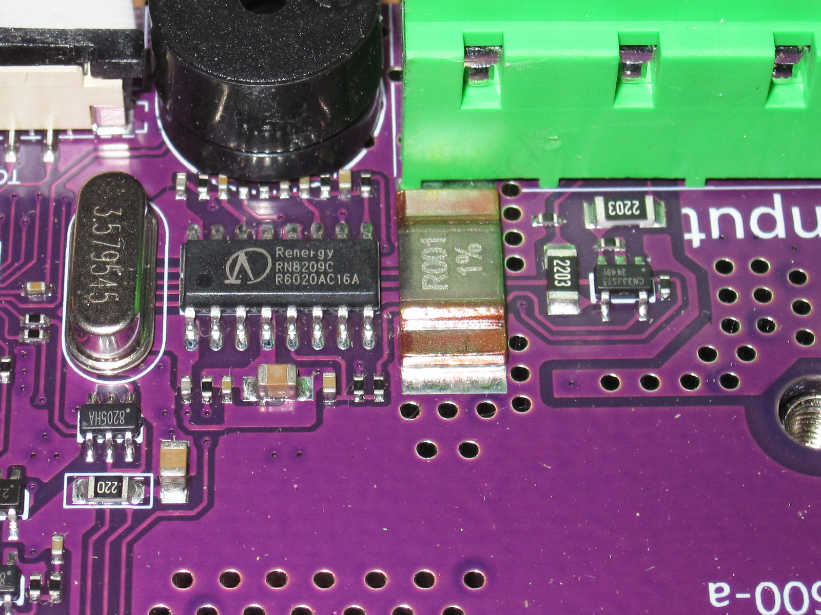
The shunt has the same rating as the one in the DL24EW and DL24MP, but the designers clearly listened to my requests and installed a proper shunt: a beefy, well-designed one. For comparison, there's a 2 W 2512 shunt next to it. The older versions had two 2512 shunts, rated at just 1 W each. So, they got it right. Kudos.
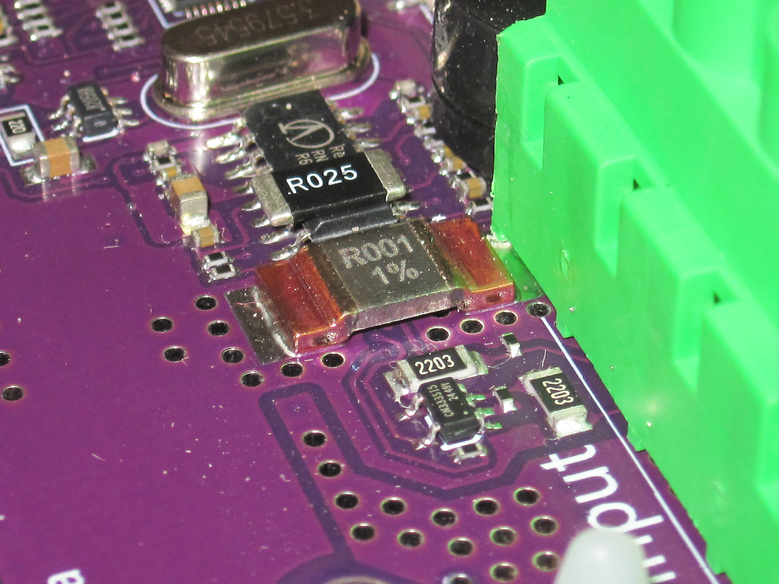
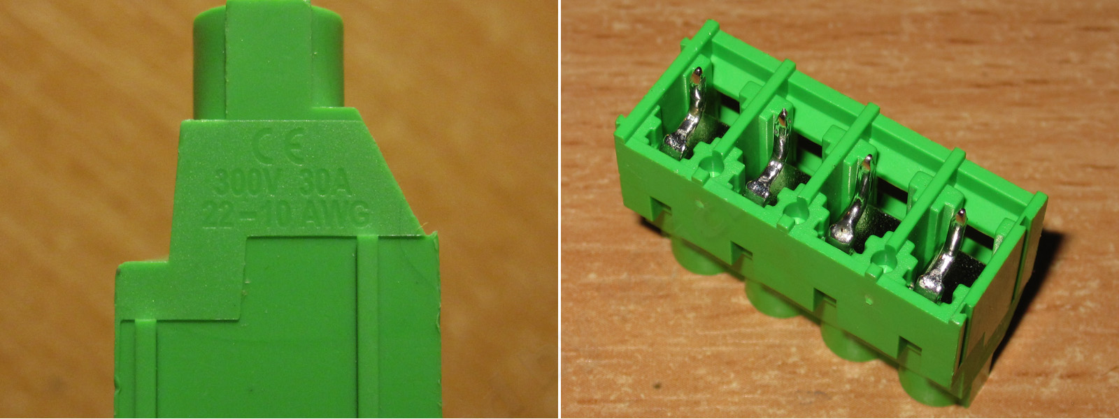
Since I bought the boards to modify them, I immediately desoldered the terminal block. I wanted to show why, during the 50 A test, I soldered the wires straight to the board, bypassing this terminal block.
The thing is, it's rated for 30 A, and even at 40 A it's working right on the edge. See those thin pins? So much for 50 A. Soldering directly to the traces is the only way—hardcore, sure, but I always desoldered this terminal block when modifying these boards. I've got a whole box of them by now :)
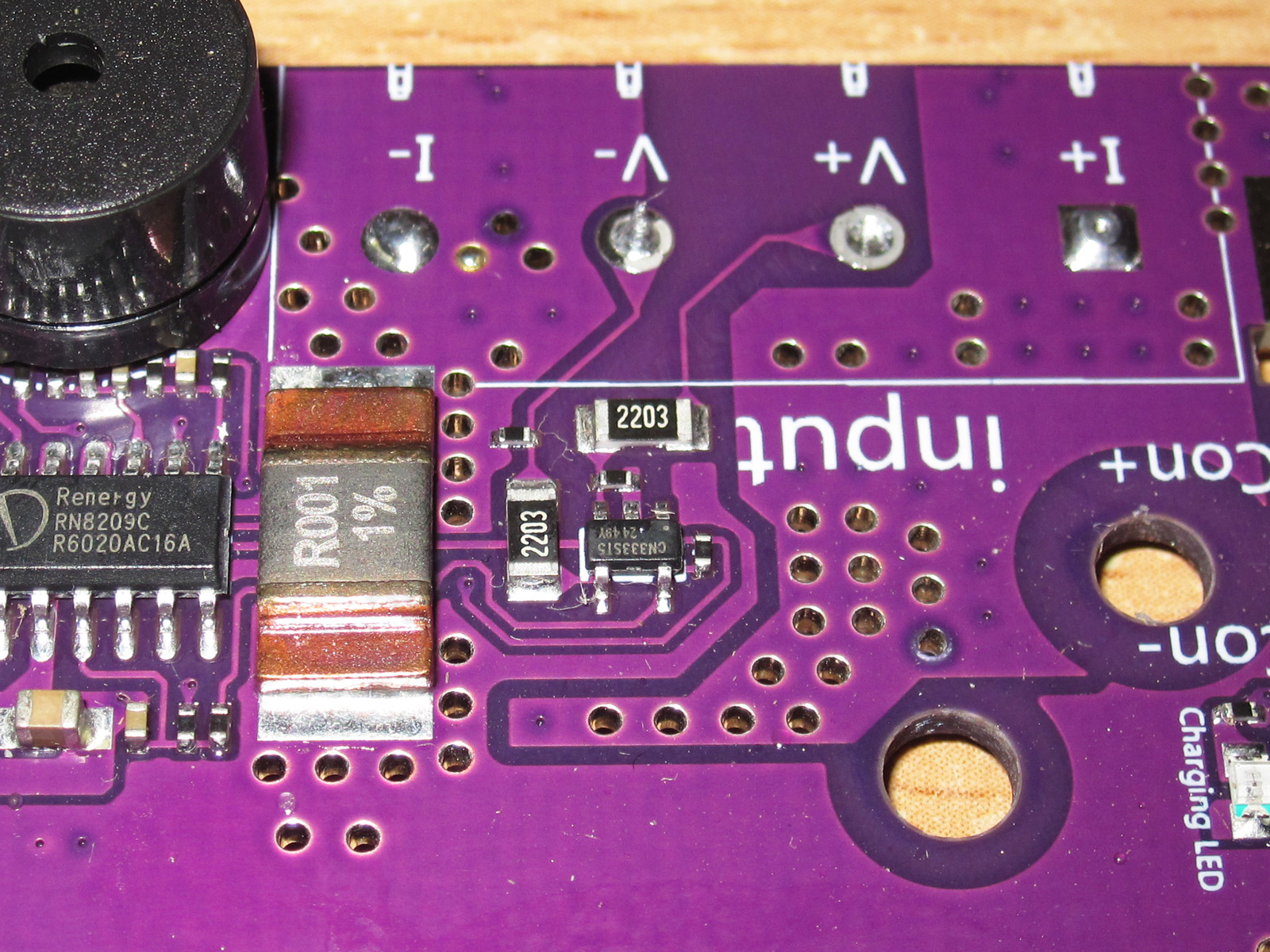
And here's another big thank-you for thinking to use a differential amplifier on the voltage measurement input.
On the older DL24 models, voltage measurement was handled by the ADC, which also has a differential input.
The DL24EW and DL24MP use different ADCs, and they installed two specifically to get four-wire connections for both current and voltage.
But something went wrong, and people started blowing these ADCs. To protect them, a 2 mΩ resistor was added to the board between the power and measurement negative terminals, turning the connection into a three-wire one. I've written about this before; I modified the circuit in my loads a little to get a four-wire connection.
Here, they used a differential amplifier, wired so that both voltage measurement inputs connect to the circuit under test through 220 kΩ resistors. In fact, you can see a small 4.7 kΩ resistor between the power and measurement negative terminals. In theory, this resistor could burn out if you mix something up while the input voltage is high. But trust me, replacing this resistor is nothing compared to repairing a board with the usual circuit. I've had to repair one like that; sometimes almost everything burns out, right down to the leads welding themselves to the traces.
Remove the transistors and, as expected, we find a temperature sensor installed in the hole in one of them. This is the right solution. Sure, it would be better to attach the temperature sensor directly to the transistor, but that's very impractical to manufacture, so this is a sensible compromise.
There were also three transistors and a 60 A diode array hidden under the heatsink, which is also the right solution. I remember the DL24MP sometimes had trouble running at maximum current. I hadn’t run into this because I did things differently (the diodes and heatsinks are lying around somewhere next to the terminal blocks :)), and I removed the original diodes from the board altogether. But users of the standard boards had complained.
According to the datasheet, the transistors are rated for linear-mode operation. I won’t say whether they’re genuine or counterfeit, since I can’t determine that with any certainty. But I can say that even in the main module they run at 50 W per case, which is perfectly fine, while in the power modules it’s only 37.5 W. So even standard IRFP264s would work here, but in my personal opinion, the ones they’re using now are noticeably better.
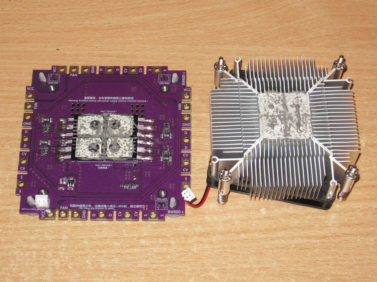
Now let’s take a look at the power module.
It looks almost identical to the main module, except, of course, that it has no “brains.”
The thermal paste covers the entire surface of the components, which is a good thing. By the way, if you want to improve heat transfer a little, you can replace it with something better, such as MX-4.
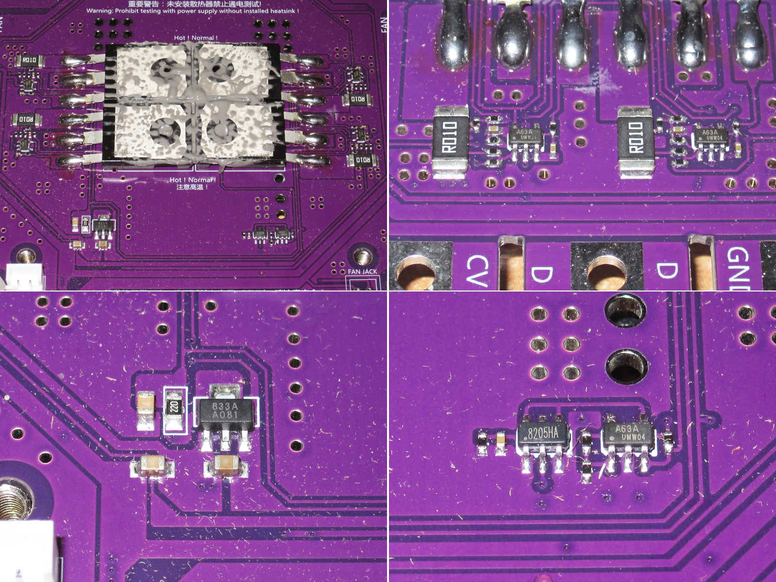
1. There are four current-regulation stages to balance the power between the transistors.
2. The current-regulator circuitry is identical to that on the main board.
3. An RC filter for the op-amp supply and a bias-voltage regulator. On the main board, this voltage comes from the main 3.3 V regulator.
4. This part was a pleasant surprise: an overtemperature protection circuit. The op-amp is used to measure the temperature, while the MOSFET stage shorts the control signal to ground if things overheat. Since this signal is shared across the whole system, including the main board, the load simply shuts off the current (or reduces it to almost zero) if it overheats. The temperature sensor is under the same transistor as on the main board, which is why there are three holes under the transistors here instead of four.
Well done—nice to see they thought of that.
As you can imagine, I don’t need the boards by themselves. 150 W is nothing, and the power modules are even less interesting to me, so I’ll probably put them up for sale. While the order was on its way, I prepared two blank electronic loads rated for 1200 W. Basically, I did everything except install the controller and finish the front panel.
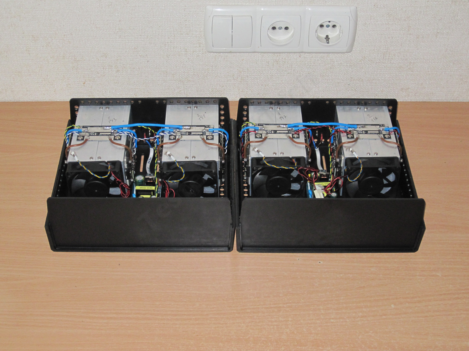
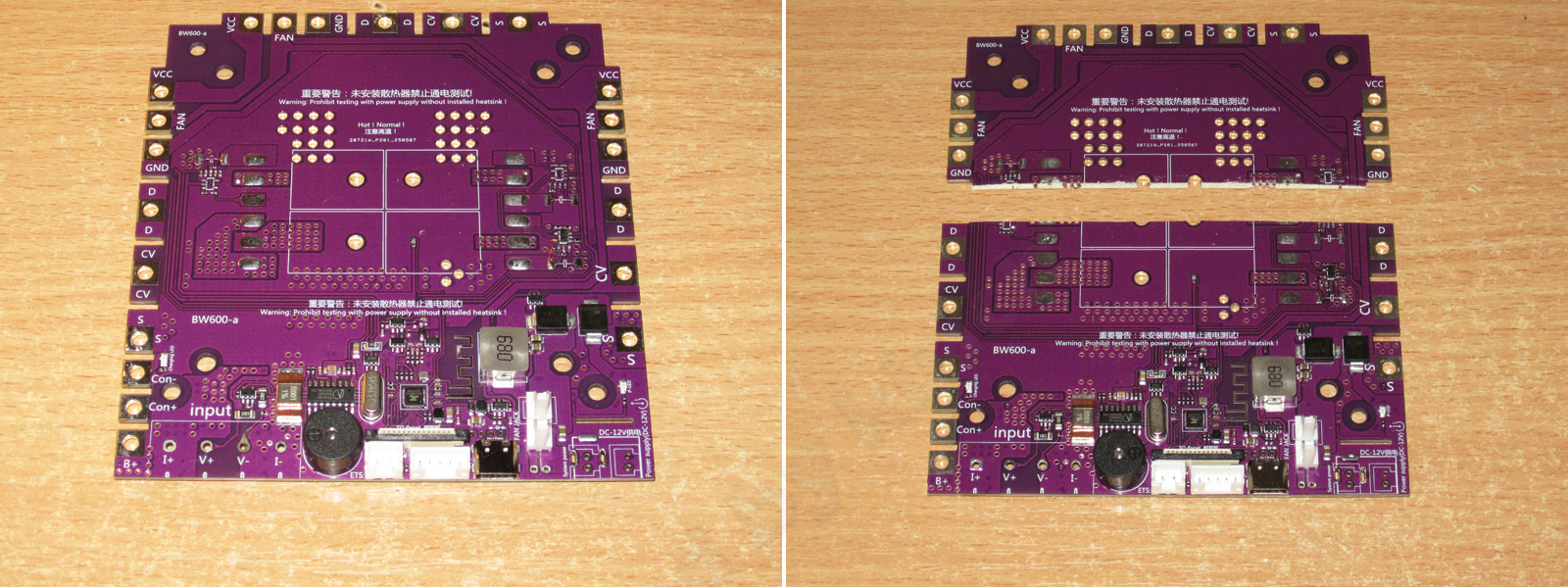
From there, it’s simple: desolder everything unnecessary from the main boards, solder in everything you need, then cut the board, because there’s no way it’ll fit as-is. By the way, the DL24MP was perfect for this: it ended up noticeably narrower and could be installed horizontally. I think I’ll miss it.
Install the modified boards in the load enclosure, connect all the wires, configure and test everything, and burn out a couple of fans along the way (well, who said switching to new hardware would be easy and painless?).
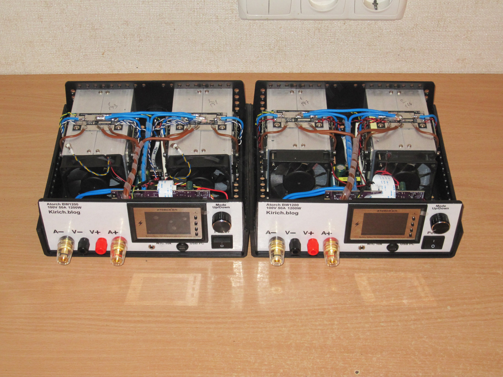
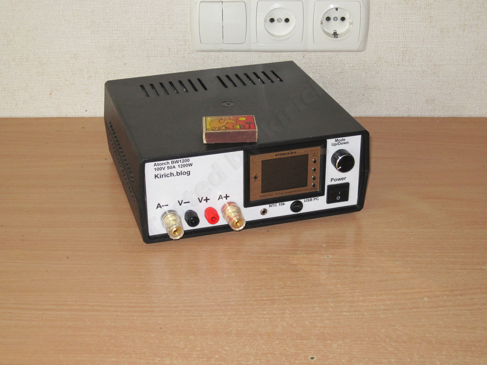
And from there, remember that picture showing how to draw an owl? It’s pretty much the same here—the owl is right in front of you :)
In this configuration, the load is rated for up to 1200 W and 50 A. And now it can do what mattered to me (and especially to someone else): load 6S packs at 50 A instead of 40 A, using the full power of the power modules.
By the way, I have a couple of complaints about the developers. They changed the controls here, just as they did on the CL24. Previously, you adjusted the value with the encoder and pressed it to confirm. Now the on/off button handles the OK function, which is inconvenient. It makes more sense to adjust and confirm with the encoder, and set the on/off button to work the way it did on the DL24MP.
In the future, the standard version may come with an XT-60 input. I also think a version with a built-in 20 A or 40 A charging switch may be possible.
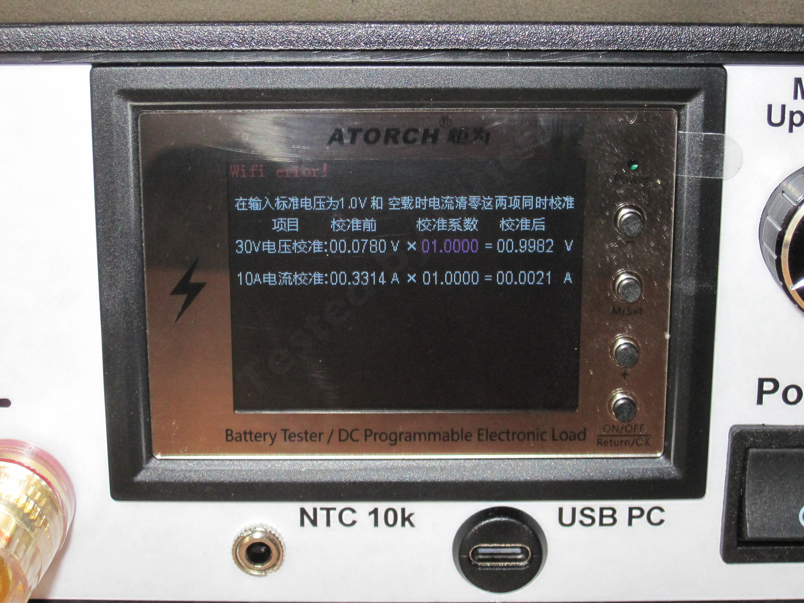
While I was at it, just out of curiosity, I pressed the encoder, as I used to do with the DL24MP—and lo and behold, the load entered low-level calibration mode. The old version had calibration points at 1 V and 30 V, and at 10 A; now they’ve kept only 30 V and 10 A.
The difference between this calibration and the one in the menu is that this one isn’t cleared when you reset to default settings. As a manufacturer of finished devices, that’s very important to me. I had so much trouble with the old DL24 units, where users could easily wipe the calibration.
But don’t rush to try this. I ran an experiment with the BW150, and it seemed to me that you can calibrate it only once, though I could be wrong. More testing is needed.
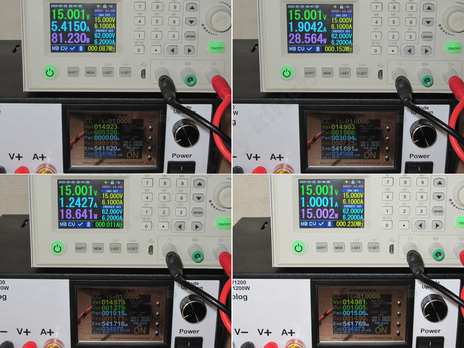
I noticed something odd during the tests with the power modules: when set to a low current, the load initially set a higher current, then lowered it. At the time, I thought I might have imagined it, especially since I was testing at high currents, where it could genuinely have seemed that way.
But after I assembled and configured my own version, I saw the glitch for myself. You set, say, 1 A and press Start, but the load immediately sets the current to 5–6 A (in my configuration), then gradually lowers it to the set value. and this is a long process, clearly not a random spike: the transition from 5.5 to 1 A takes... 20 seconds, as you can see from the timing on the bench power supply.
I thought I’d done something wrong, but it turned out to be the opposite: I’d actually minimized this spike because, unlike when using the original power modules, I’m using about 95–95% of the DAC’s operating range.
Let me explain.
Suppose our hypothetical DAC has an adjustment range of 0–2.6 V, and with 1–2 modules (including the main one) we just about cover it (the difference between 30 and 50 A is almost a factor of 2, just like the difference in the number of modules).
But if we connect two more modules, the same 50 A will be reached at 1.3 V instead of 2.6 V. If we double the number of modules again, the same 50 A will be reached at just 0.65 V. In other words, doubling the number of modules effectively reduces the setting accuracy by 1 bit.
But there’s a worse problem. I’ve just received some more of these boards and tested one of them. When I was testing operation at low currents, I noticed that the load had a nice soft start. It turns out that with one module, yes, we get a soft start across the entire current range. But if we configure it for the main module plus one additional module, we get a spike even with no module connected. In other words, this is purely a software bug.
I simply increased the number of modules in the settings without connecting them, and the spike grew with each step: for example, 1.3–1 A, 1.6–1 A, 2–! A. If I’d connected the power modules, the spike would have been even larger.
Why would the spike be larger, and why does it increase as the number of modules goes up?
As I mentioned above, increasing the number of modules makes the control voltage more sensitive. In other words, the relative size of the spike has a much greater effect on the current.
Suppose 2.5 V gives us 50 A with two modules, and a 5 A spike corresponds to 0.25 V. But with four modules, 0.25 V gives us 10 A instead of 5 A. With eight modules, that same 0.25 V gives us 20 A instead of 10 A. With 20 modules, the spike would effectively equal the full current.
Since my loads aren’t universal, I adjust the DAC’s full range to match the current of my modules. So even at 1200 W (although the settings say 1800, the limit is set to 1250 W), the spike is only a little over 5 A, which is tolerable. In the kits sold by Atorch, this spike will be noticeably larger.
If the developers read my review, I think they’ll be able to fix this bug, since it’s clearly a software issue and everything works perfectly with just the main module. And once again, I’d like to ask them to get in touch with me.
And of course, I had to test it. First, I balanced the battery, since all these experiments had thrown it badly out of balance.
Then I connected it to the load and set the discharge current to 50 A.
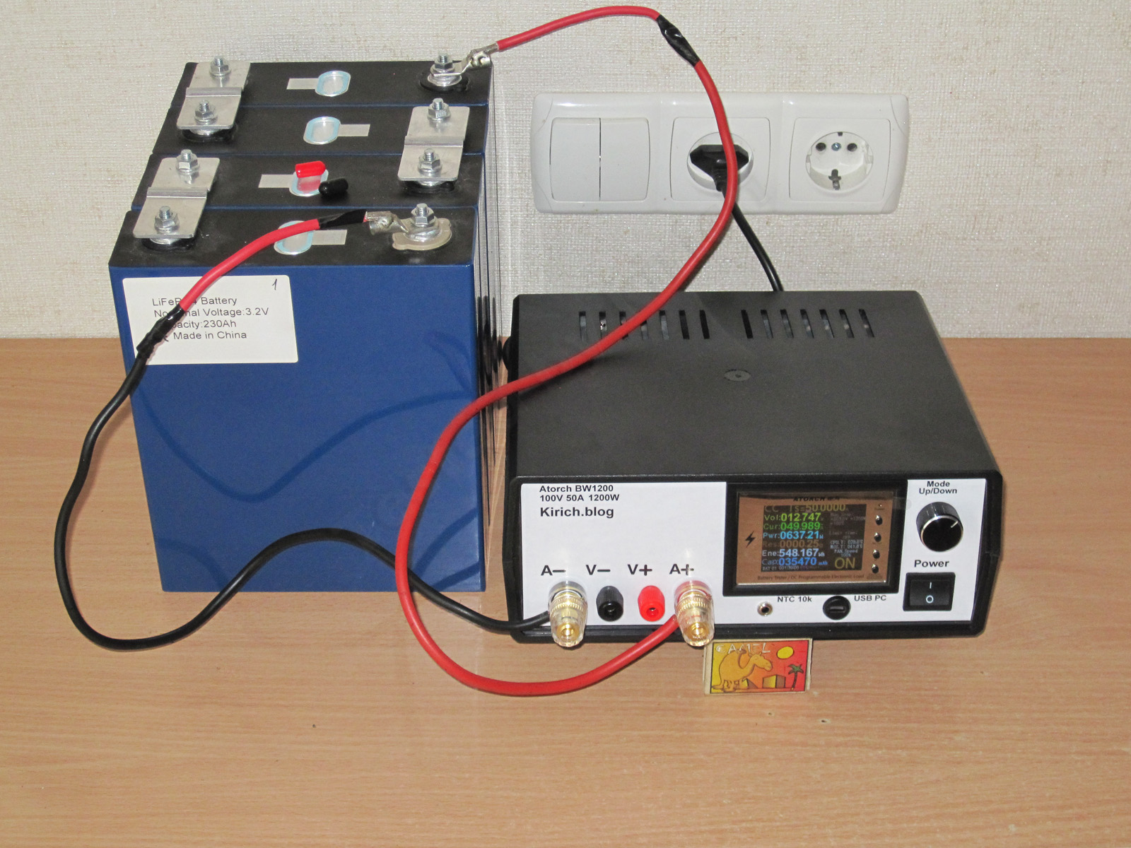
In reality, because of the automatic current regulation, it fluctuated a little, from about 48.9 to 50.2 A. By the way, reducing the adjustment range, as I mentioned above, will increase these fluctuations proportionally, but that can only be corrected in hardware. The DL24EW and DL24MP had a jumper for this, if you remember. That jumper was specifically for adjusting the control voltage according to the number of modules.
The current was 50 A. I didn’t make any adjustments; I simply resoldered the shunt and soldered the wires directly to it, which reduced the resistance slightly and brought the current back to normal.
In the end, I still got an overcurrent warning, of course, but now they should happen less often. Also, I can try to get rid of them altogether, although everything works fine already when the current is set to 49.5–49.8 A.

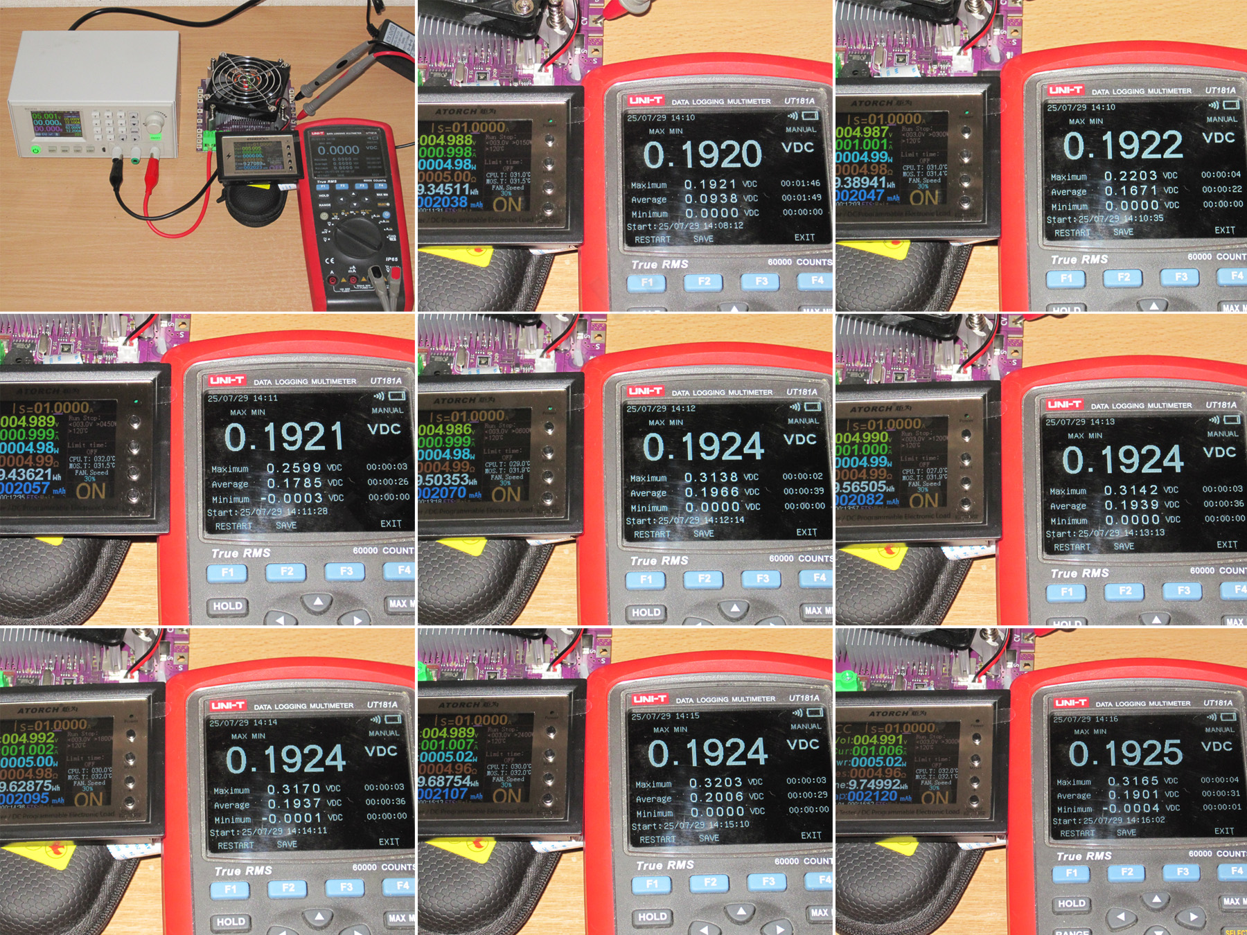
After publishing the review, I decided to measure the size of the spike in different configurations. I’d originally wanted to calculate the total current, but the relationship isn’t entirely clear to me. For example, at a control voltage of 0.192 V, the current was 1 A, while at 0.32 V it was already 2.5 A.
But it’s clear that the maximum occurs with the base plus 3 modules, i.e. 600 W, and this voltage is 0.32 V. As you add more modules, the spike stays at the same level, but the current increases in proportion to the number of modules.
I can say that during testing I measured the control voltage with the base unit plus 3 modules. It was 0.37 V at 12.5 A and 0.60 V at 25 A, so I initially got about 10 A, which then dropped to the lower set current.
Before wrapping up, here are the available bundles, add-on components, and links to them.
The store has discounted some items, but has limited purchases to 1 per person.
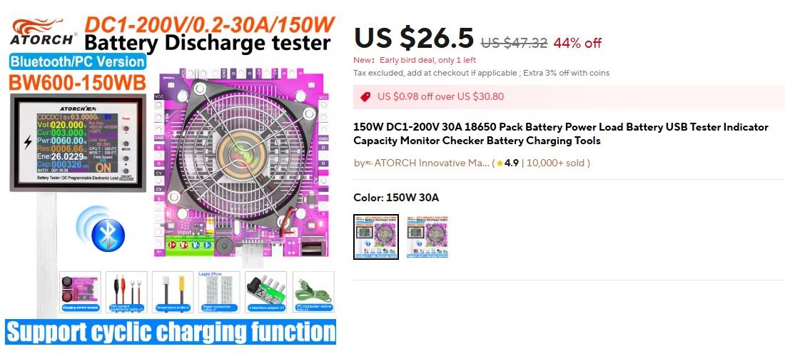
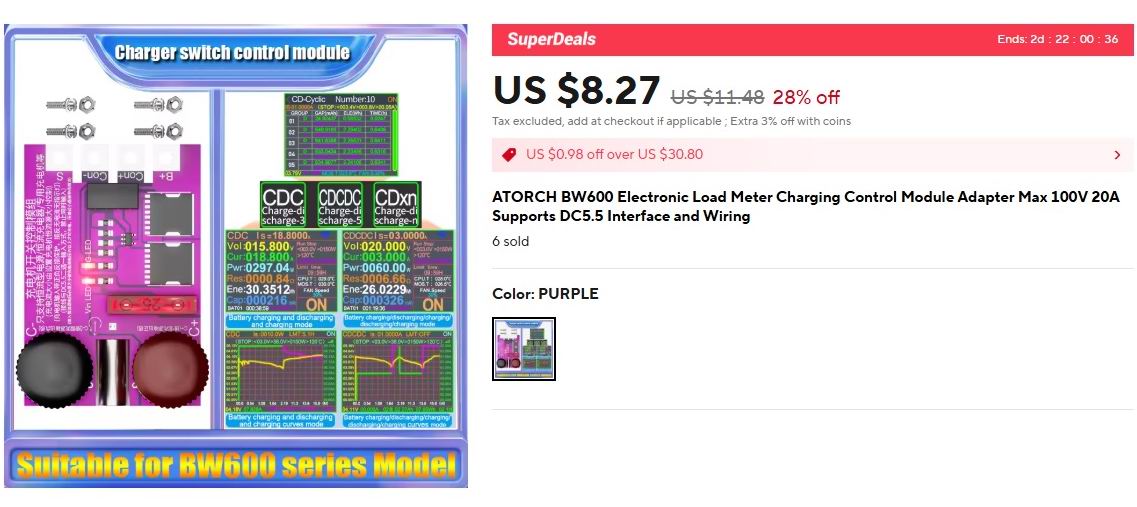
First, the basic version, available bare (without WiFi) or bundled with the switching board: link
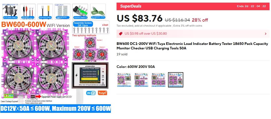
The full kit, with additional modules, WiFi, and all the extras: link.
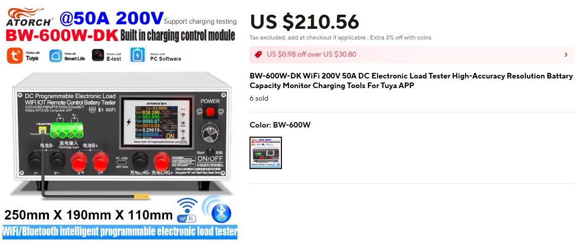
A ready-to-use electronic load based on this board: link.
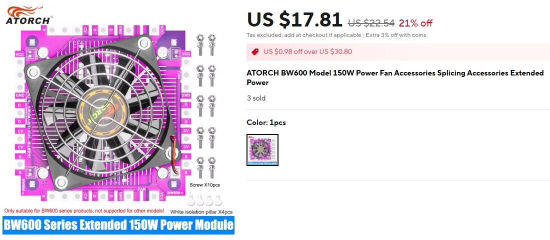
Power modules: link
Switching board: link
There are no actual photos yet, only renders. The transistor type is unknown; the specs claim 20 A and 100 V.
The board is quite similar to mine in many ways. You can clearly see that it now disconnects in both directions, rather than just one. But unlike mine, it has neither reverse-polarity protection nor a polarity indicator. As for why I rate my board at 50–55 V, that's because I know what voltage it will see if the polarity is reversed, and I think the transistors have the same voltage rating.
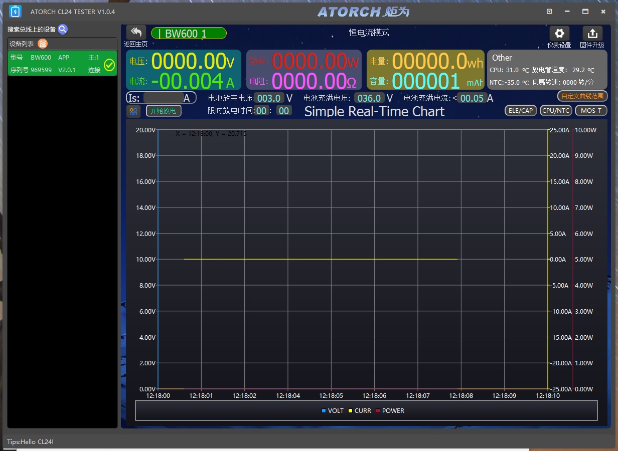
Almost forgot: the PC software is the same as for the CL24 and BW150, so I have a huge request: please finally add the ability to work with several loads at the same time—at least 4–8, preferably 16. People have asked me about this repeatedly. Running two copies of the program doesn't solve the problem; you can only work with one load at a time.
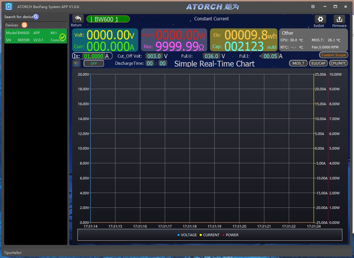
It turns out there's a new software version specifically for the BW150 and BW600 loads. I downloaded it and installed it, but didn't notice any difference from the previous version.
Conclusions.
It might be easier if you ask questions in the comments and I answer them, since I'm bound to forget some things.
But I can already say that, all things considered, the new version is better overall than the old one, because it now has:
1. USB, and WiFi on some versions, not just Bluetooth (it has Bluetooth too).
2. Control of the charger's switch and the ability to run cycle tests
3. New features, such as battery testing and power supply testing with mode switching.
4. Graph display, like the DL24EW
5. A proper current-sense shunt
6. A better transistor current-balancing circuit
7. A differential amplifier on the voltage measurement input
8. Fan speed control
9. Current up to 50 A
10. Essentially the same price as the 24MP, at least for now.
11. Thermal protection for the power modules
12. Works with the new software; the load itself is also built around a new controller and new software.
13. Reverse-polarity protection for the load's power input
There are also:
1. A current spike when using additional modules
2. A narrower DAC range when using more than two power modules (including the main one)
3. Encoder control that's not as convenient as on the 24MP
4. They kept their favorite 30 A terminal block in a load rated for up to 50 A
5. The fan turns on not only during operation, but also just after pressing the buttons.
6. The software can control only one load.
7. Something else—I don't remember; look through the review.
As you can see, there are still more advantages than drawbacks. I think some of the drawbacks can be fixed in software, which is partly why I'm asking the developers to get in touch with me. If the price is the same as the 24MP and 150 W is enough for you, it's an easy recommendation. If you're willing to put up with the current spike and reduced current-setting accuracy, you can get it with the modules—or write to me and I'll explain how to modify it.
Otherwise, I liked the load, and if the drawbacks are fixed, I'll be completely happy with it :)
That's all for today. I hope this information was useful, and I'd be very glad to hear your questions or just your comments.
$26.5
This page was found when searching for:
dl24mp настройка, atorch bw 600 как пользоваться, dl24mp kirich, электронная нагрузка atorch dlb600, atorch bw600 модуль управления зарядкой, atorch bw600 разъем, atorch bw600-series инструкция, форум bw600 электронный измеритель нагрузки, модуль для bw600, 3, https://mysku.club/blog/diy/85766, atorch dl24mp 600w, atorch dl24mp тестер аккумулятора 600 вт, корпус своими руками для bw600 atorch, отличия версий нагрузок atorch, atorch bw600 инструкция, bw600 инструкция, atorch bw600, atorch bw600 корпус, dl24 новаяверсия отшичия, attorch bw600, atorch dl24mp или atorch bw600, 4, обзор atorch bw-600w-dk тестер аккумуляторов, https://www.kirich.blog/obzory/izmeritelnoe/1280-atorch-bw600-prodolzhenie-lineyki-nagruzok-dl24mp
dl24mp настройка, atorch bw 600 как пользоваться, dl24mp kirich, электронная нагрузка atorch dlb600, atorch bw600 модуль управления зарядкой, atorch bw600 разъем, atorch bw600-series инструкция, форум bw600 электронный измеритель нагрузки, модуль для bw600, 3, https://mysku.club/blog/diy/85766, atorch dl24mp 600w, atorch dl24mp тестер аккумулятора 600 вт, корпус своими руками для bw600 atorch, отличия версий нагрузок atorch, atorch bw600 инструкция, bw600 инструкция, atorch bw600, atorch bw600 корпус, dl24 новаяверсия отшичия, attorch bw600, atorch dl24mp или atorch bw600, 4, обзор atorch bw-600w-dk тестер аккумуляторов, https://www.kirich.blog/obzory/izmeritelnoe/1280-atorch-bw600-prodolzhenie-lineyki-nagruzok-dl24mp
The figures from this review are in the measurement database: Electronic loads
Discounted products
You may be interested in


Discounted products
Support the project
All the content on the site and the advice are free, but we’d be grateful for your support of the project and the channel!
Comments22
Discuss on the forumHave a question or some experience to share? Discuss the article with the author and readers: the forum is a convenient place to share schematics and photos.
Go to the forumOnly registered readers can comment. It takes a minute to sign up, and you can log in with the same account you use on the forum.
Log inRegister
Comments are published in their original language.