
Four compact sealed power supplies: 10, 24, 36 and 50 watts, plus a bonus
You can never have too many power supplies. I thought so too, which is why today I'm doing a quick review of four compact, sealed power supplies, plus a bonus: a fifth unit. It's not exactly compact, but it is sealed. And that's not the last of the bonuses—look for one near the end of the article :)
A reminder: to keep up with new topics on the blog, I recommend following me on Instagram, where I'll post notifications about all new topics and maybe write about something interesting too - link to my account
You can also subscribe to updates and new articles on the Telegram channel - https://t.me/KirichBlog
Since these power supplies are sealed, their descriptions will be much simpler and will mostly consist of tests and some conclusions based on them.
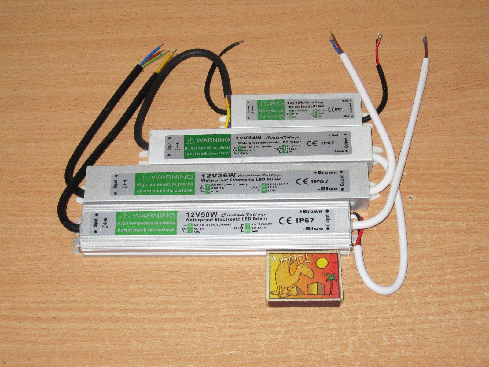
First, the main players: four slim power supplies, well suited for all kinds of built-in applications in light fixtures, LED signs, and more.

I'll start with the smallest model, rated at 12 V and 10 W. Yes, it's a little guy like this, though “little” is relative.

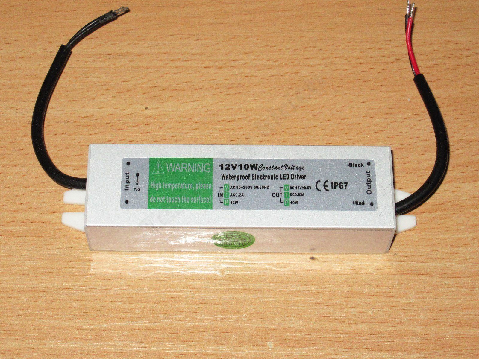
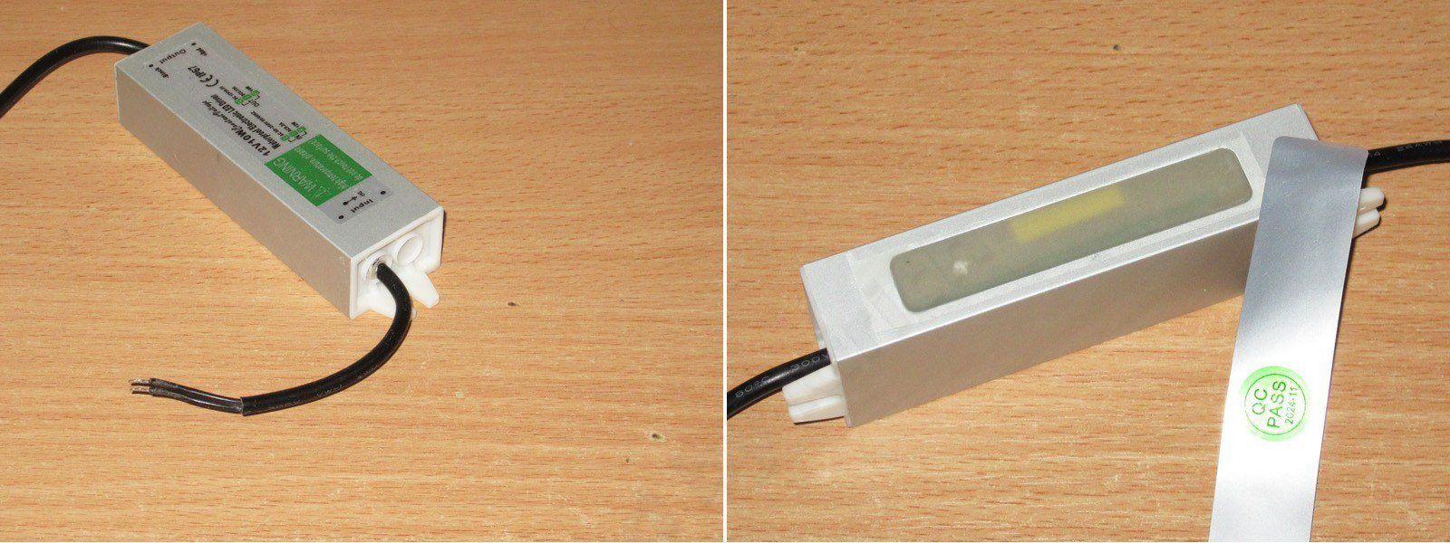
The case is made from an aluminum extrusion, with plastic end caps and the internals potted in compound. There is a small window under the label, though, through which you can get a glimpse inside.
The case measures 96(115) x 29 x 20 mm.

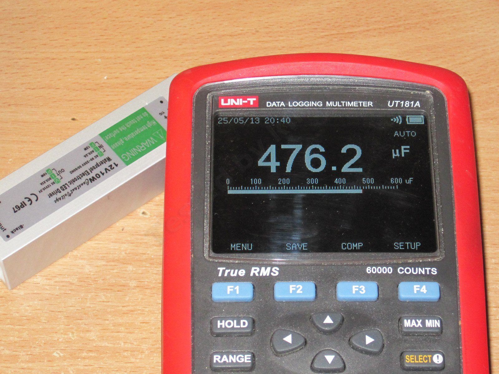
It's very awkward to measure the input capacitor's capacitance, but the output capacitor is easy to access, and its capacitance is clearly around 470 µF, which is quite enough for a power supply like this.

Why did I say the power supply is “relatively” small? Because I often use power supplies made by Sanmim. For example, here's a 6 W power supply that can actually deliver 9 W continuously, and includes an input inductor, a varistor, and a thermistor. It also has two capacitors and an inductor on the output, i.e. a filter to reduce ripple. I think if you put a board like that in a metal case and pot it, it could deliver 10 W too :) And here's a 12 W power supply from the same manufacturer, which can also run at a higher power.

I used a ZKEtech EBC-A10H battery tester for measurements and testing; it's more convenient for plotting graphs.

The tests will be roughly the same for all the models. First up is a test to find the overload protection trip point. I tested with input voltages of 230 and 115 V.
And here I have to say I wasn't happy with the results. At 230 V, the power supply shut down at a current above 2.5 A; at 115 V, it shut down above 2 A. So in practice, that's about 2–3 times the rated value.
That's not great, because you can load the power supply well beyond its rated power and it will fail simply from overheating, without the protection even making a peep. In my opinion, the protection trip point should be around 20–25% above the rated power, 50% at most, and at least 10% to avoid false trips. In any case, it should never exceed the level at which the power supply can operate reliably over the long term. The protection threshold also depends heavily on both the power supply's rating and the type of load.
One thing is somewhat reassuring: the protection has a threshold, and at 115 V the trip point is noticeably lower than at 230 V. In terms of power, the difference is as much as a factor of one and a half.

Test two: assessing the output ripple level. As usual, I measured two types of ripple: high-frequency and low-frequency.
I tested at load currents of 0.5, 1, and 1.5 A. In fact, even 1 A is a slight overload.
The ripple amplitude is almost independent of the load current and is around 300–400 mV. Unfortunately, that's not very good, but it's still quite adequate for powering all kinds of lights and backlights.
At low frequencies, you can see some spikes at 100 Hz. Interestingly, they have a well-defined shape. In any case, I have no complaints about the low-frequency component.

Load test: I again tested at load currents of 0.5, 1, and 1.5 A, for about 20 minutes at each step.
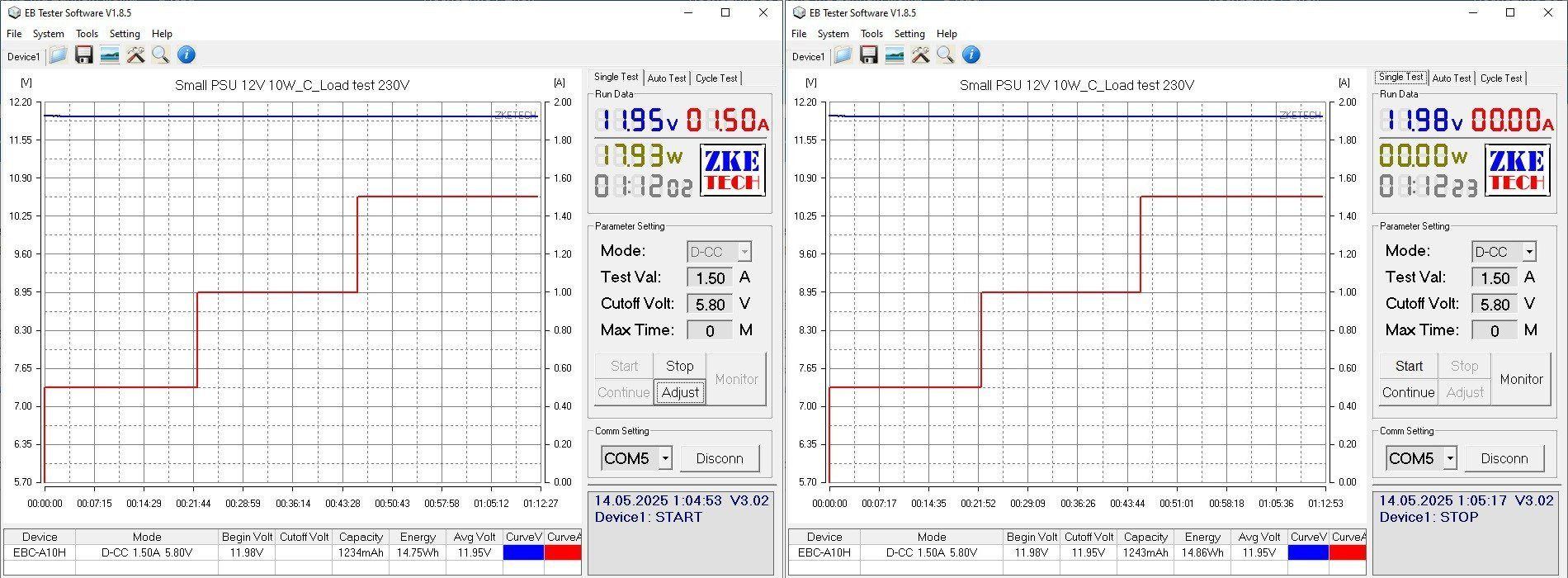
There are two graphs so we can see what the voltage was initially (the line at the bottom left), what it was at the end of the loaded test (the first graph at the top right), and what it was after removing the load (the second graph at the top right).
For example, this power supply started at 11.98 V. After warming up under load, it was at 11.95 V; after removing the load, it returned to 11.98 V.
That is, In practice, we have zero voltage dependence on temperature and only minimal dependence on load current—an ideal result, especially considering the nearly twofold overload.

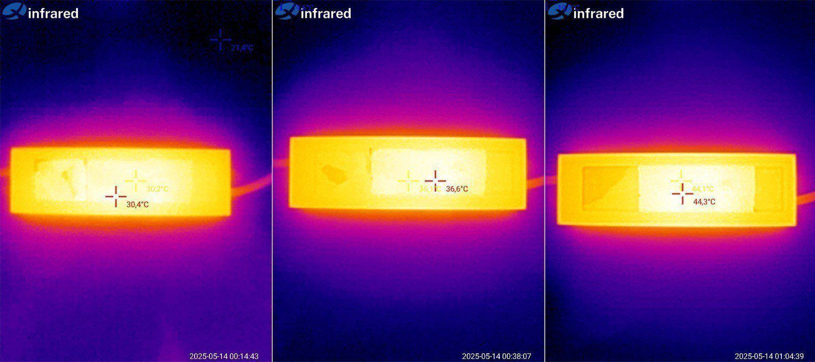
Case temperature after testing at 0.5, 1 and 1.5 A. A piece of electrical tape was stuck to the case to improve measurement accuracy.
It's hard to judge here: the case is warm, but it's impossible to tell whether there are any localized hot spots because the components aren't accessible.

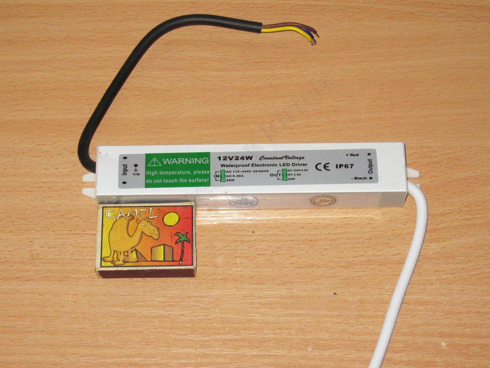
The second power supply, 12 V, 24 W.
Noticeably longer than the previous one: 162(180) × 29 × 20 mm.

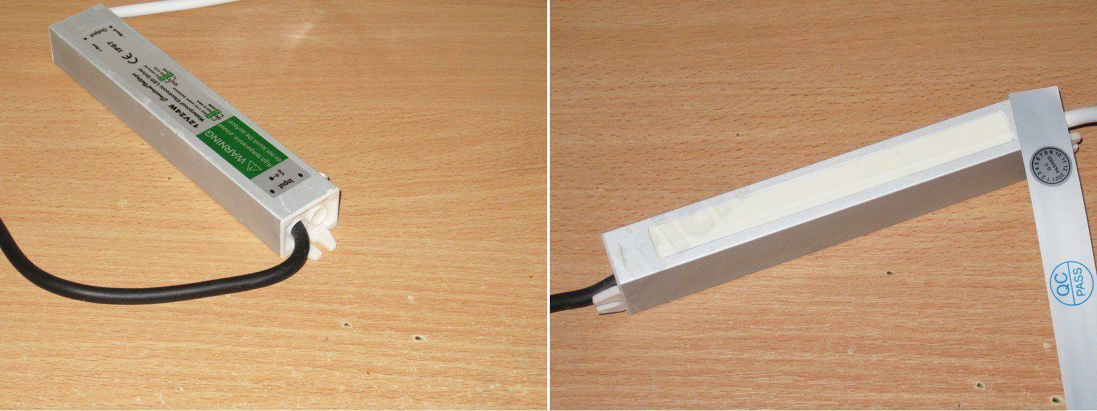
The design is identical; the only difference is that the potting compound here is opaque.

Apparently, there's a single 2200 µF capacitor on the output, which is more than enough for a 24 W power supply.

Interestingly, the protection trip current here doesn't depend on the input voltage. The input capacitor may also have a higher capacitance.
The protection trips at around 3 A, or roughly 50% above the maximum current, which is within the acceptable upper limit.

Ripple was measured at load currents of 1, 2 and 2.5 A, i.e. at up to 125% load.
And I have to say, the results are pretty good. Even at maximum load, the peak-to-peak ripple is around 200–250 mV. The low-frequency component is also fairly small, which indirectly suggests that the input capacitor has sufficient capacitance.

This test was run at 1, 2 and 2.5 A, with the same intervals of about 20 minutes each.
At the start of the test, the voltage was 12.19 V; hot under 125% load, 12.13 V; and with no load, 12.16 V. Practically perfect.

The case temperature is also fine.

The third model, 12 V, 36 W.
The case measures 201(221) × 29 × 20 mm; the only difference from the previous models is the length.

The design is similar to the previous models. You can just about see the transformer through the window; it's larger than the one in the 10 W version.

The 1000 µF output capacitance left me puzzled. The 10 W model had 470 µF, the 24 W model had 2200 µF, and this one has just 1000...

The protection trips at roughly the same current, 3.4 A, at both 230 and 115 V. The only difference is that at 115 V, the voltage started to drop noticeably before the protection kicked in.
In any case, the trip threshold is about 10–15% above the maximum current, which is actually pretty good.

Since the protection threshold is very close to the maximum current, I checked ripple at 1.5 and 3 A.
Well, it's clear that 1000 µF isn't enough here: the high-frequency ripple is around 400–600 mV peak-to-peak, while the low-frequency ripple isn't that large. The input capacitance may be relatively high; the similar protection trip thresholds at 230 and 115 V also point to this.

The temperature test was run at 1.5 and 3 A. I had to repeat the test to check how the voltage changed; each stage actually lasted about 20–25 minutes.
The initial voltage was 11.77 V; warmed up under full load, 11.69 V; warmed up with no load, 11.79 V. Results close to ideal.

I also had no complaints about the case temperature, although there are three possibilities here:
1. Bad: the potting compound has poor thermal conductivity, so the components are actually much hotter.
2. Good: the power supply is efficient, so it generates little heat.
3. In between: the case is simply large, so the heat is distributed well.
I hope it's at least the third option.

The fourth power supply, 12 V, 50 W.

The design differs slightly in both the case profile and its dimensions: 185(205) × 34 × 23 mm. You can see that the case is shorter than the 36 W version, but wider and thicker, and it also has extra fins, which is very useful.

The output capacitance is 2200 µF, just about enough for the rated specs.

The load graph shows that the protection threshold is set much too high. It also clearly uses a different controller, since the voltage drops gradually at the end. In other words, the power supply has essentially switched to power limiting, reaching about 100 W despite being rated for 50 W. That's far too much.
But there's a worse problem: during a test at 115 V, the power supply failed. At first it went quietly, but when I tried applying 230 V, there was a bang, a little smoke, and a black streak of soot on the table.
What a shame. I really should have run this test last. To be fair, though, this is the first power supply I've had die during a test like this.
This is also a clear example of why you shouldn't set the protection threshold too high.

But even a burnt-out power supply can be useful: you can take it apart and see what's inside. Now I definitely don't mind poking around in it :)

After a while with tweezers, a knife, and a few other tools, we get a look inside.

There was an insulating pad inside, too. Nice. But the first thing I noticed was how small the circuit board is. It takes up just over half the case; the rest is just potting compound and wires.
Interestingly, the potting compound inside is gray, while the end caps were white. Most likely, they filled it with compound and fitted the end caps at a different stage.

The circuit board really is quite small. There's no input filter, and no output filter either. And as you can see, there are soot marks; it looks like part of the board simply burned out.

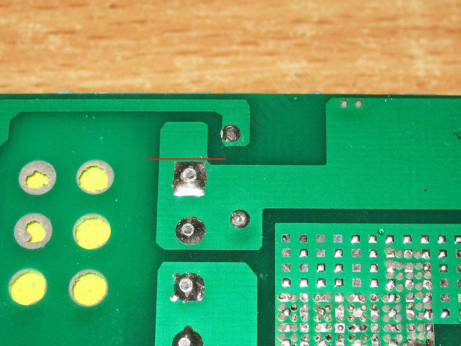
The underside is simple and neat. I do have one question about electrical safety: what idiot put a copper pour from the transformer so close to a trace on the hot side? There's plenty of room to provide a decent clearance here, but for some reason they made it smaller. The only thing that helps at all is that the board is potted.

Even trimming the copper pour along the line would make things noticeably better. Though I didn't look too closely at what's on the other side of the board.

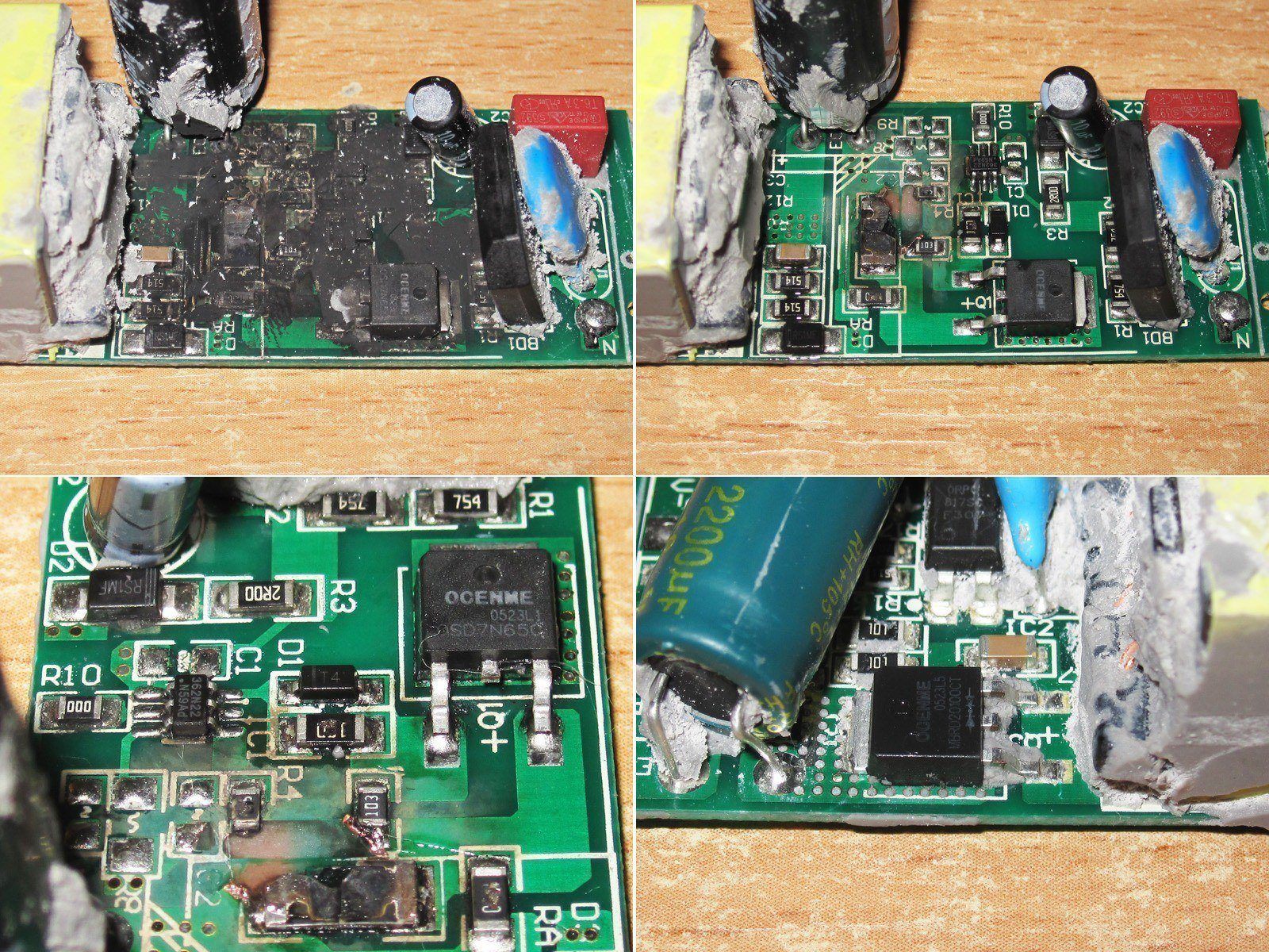
1. There's a varistor on the input, which is a nice and unexpected touch. The input capacitor is 47 µF, which is basically fine for a 50 W power supply running from 230 V, but a bit small for 115 V. Still, that's typical of Chinese power supplies.
2. The actual capacitance is slightly lower, but within tolerance.
3. The interwinding capacitor is the right type, though the markings are hard to read.
4. The output capacitor is rated for 16 V and 2200 µF, just as I measured above.

1, 2. Grab some cotton and alcohol and clean the board. Well, the damage isn't actually that bad, and the board could probably be repaired, but honestly, I can't be bothered.
3. The transistor is rated for 7 A and 65 V, which is perfectly fine for such a small power supply.
4. The output rectifier assembly is rated for 20 A and 100 V. It's unusual to see those specs in such a small package, but they're probably there to reduce the voltage drop, since it's still hard to dissipate much power from a package this size. Either way, that's very good.
My guess is that the transistor failed first, but the transformer limited the short-circuit current, so nothing else burned out. Then I connected it directly to 230 V mains, and things went downhill....

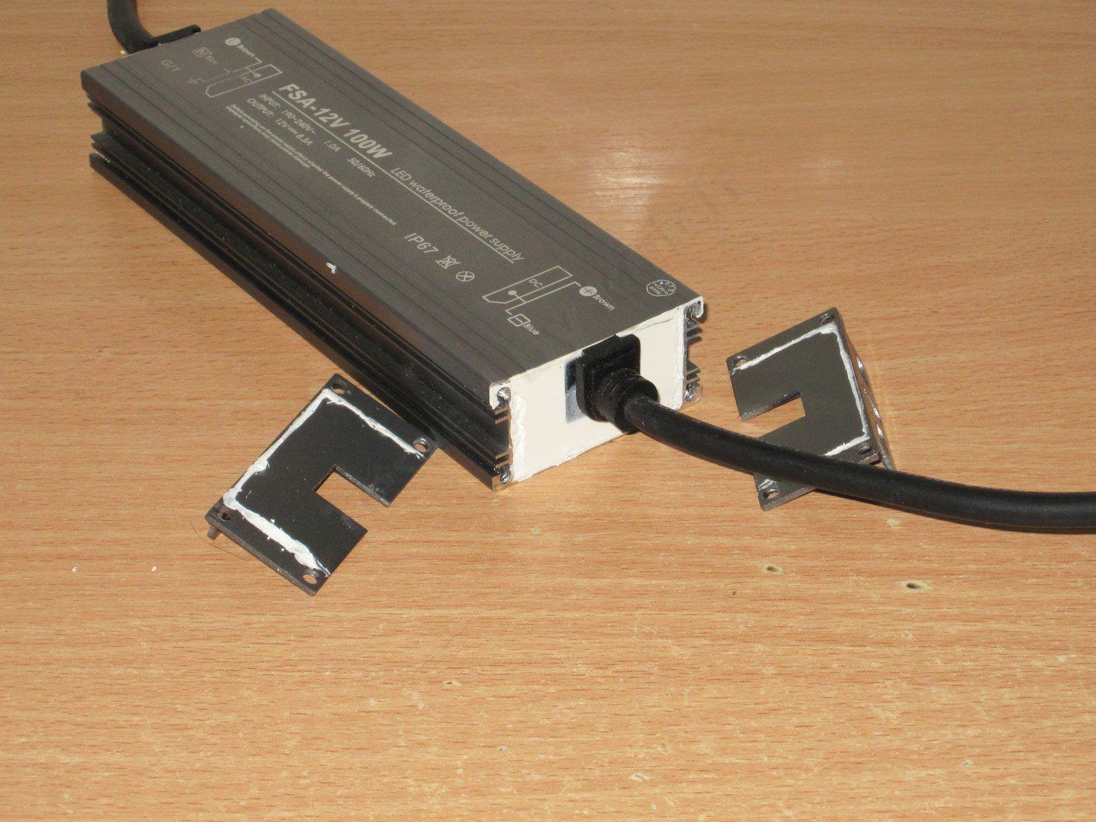
The fifth power supply is the FSA-12V 100W, rated for 12 V and 100 W.
This one made it into the article mostly "for company," since there's not much point in giving it its own article. So it's an extra bonus—and you could count the teardown as a bonus too :)
Case dimensions: 165(185) × 53 × 26 mm

The design is similar to the previous model, but noticeably larger in cross-section. The cable with the plug ended up here by chance and isn't included.

It turned out that the protection is set almost exactly at 60 W—just barely. I'd even say it can handle 50 W with some headroom, but the tests will tell us more about its actual power.

Ripple at currents of 2, 4, and 5.6 A. At high frequencies, things look pretty good here: 150–200 mV is perfectly acceptable.
At low frequencies, though, 100 Hz ripple is clearly showing up at 5.6 A. It’s not exactly critical, but it is noticeable.

The load test here was run straight at the maximum possible power, about 60 W, for roughly an hour and a half. I tested it the same way at both 230 V and 115 V input; I only ran the previous power supplies under load for an extended period at 230 V.
At the start of the test, the output was 11.89 V. Once warmed up under load, it was 11.81 V. After removing the load, it was back at 11.89 V, just like at the start. Excellent.

The case temperature was 50°C at 230 V and 53°C at 115 V input, which is also quite good. I even got the impression that this was originally a 100 W power supply, later limited to 60 W. Though I think it would get pretty hot at 100 W.

Don’t worry, nothing burned out. I’m taking the power supply apart as planned; the person who sent it to me asked me to do so for a rough look at its internals.

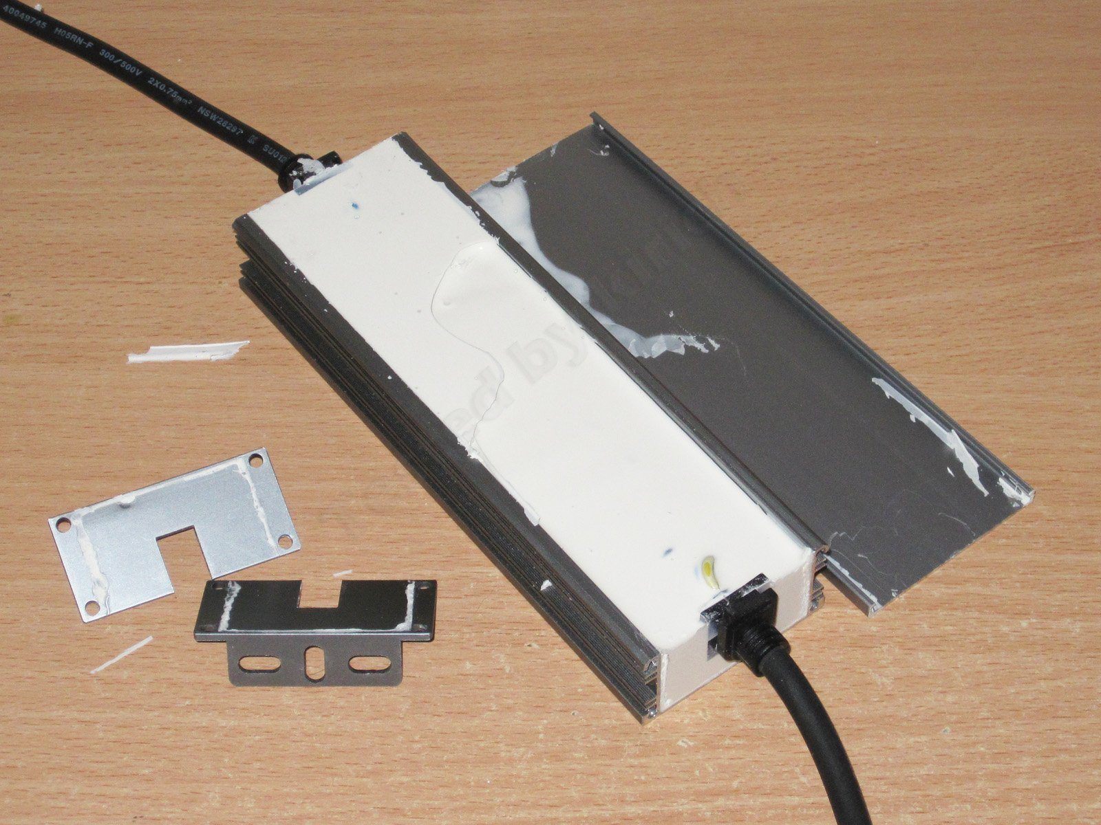
It’s thoroughly potted, no complaints there.

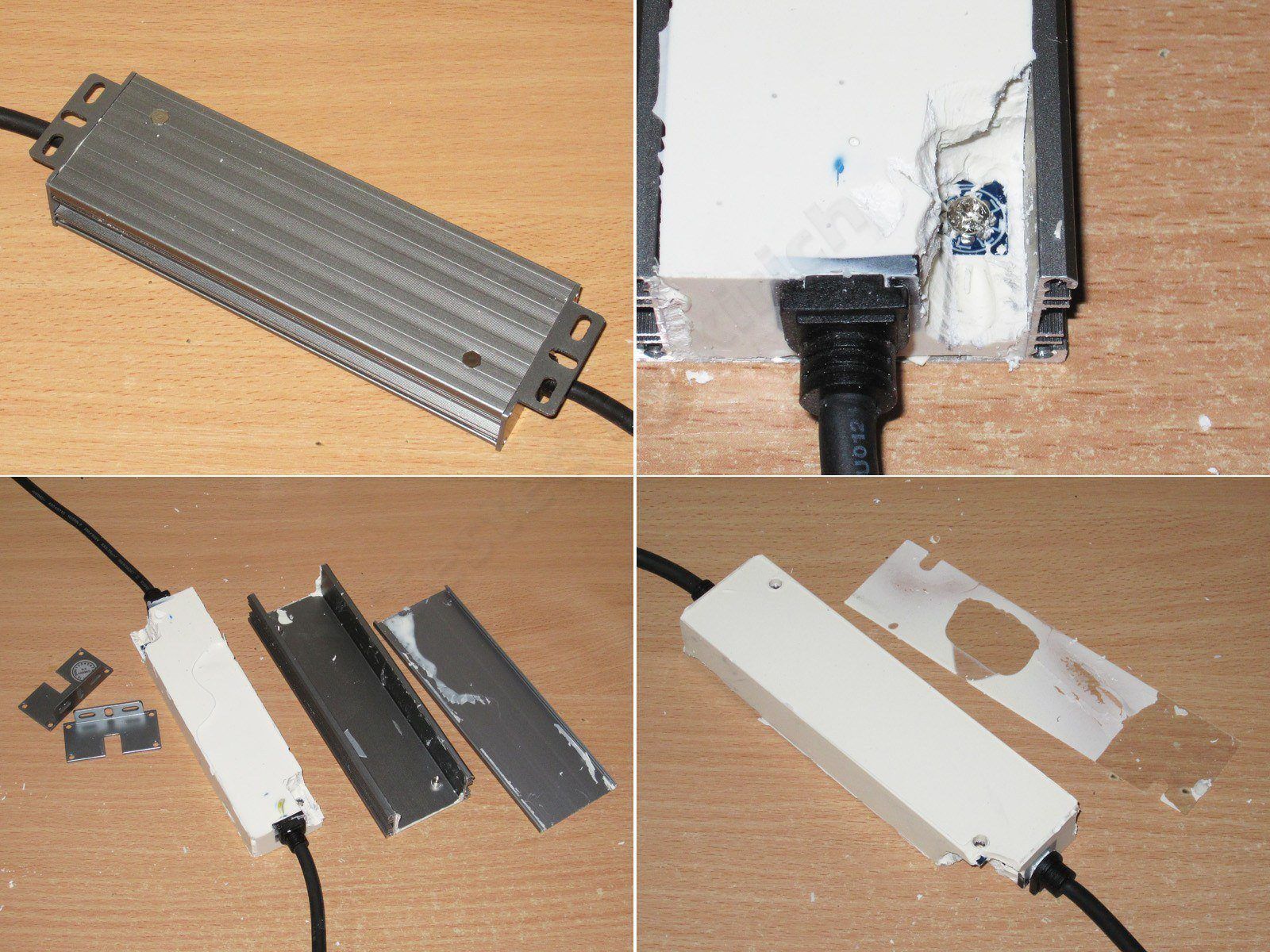
But what can stop someone who wants to see what’s inside? :) Actually, I got lucky that power supplies like this are potted with relatively soft compounds. When you dig into industrial equipment, you can run into stuff like epoxy resin, and then you’re in trouble...
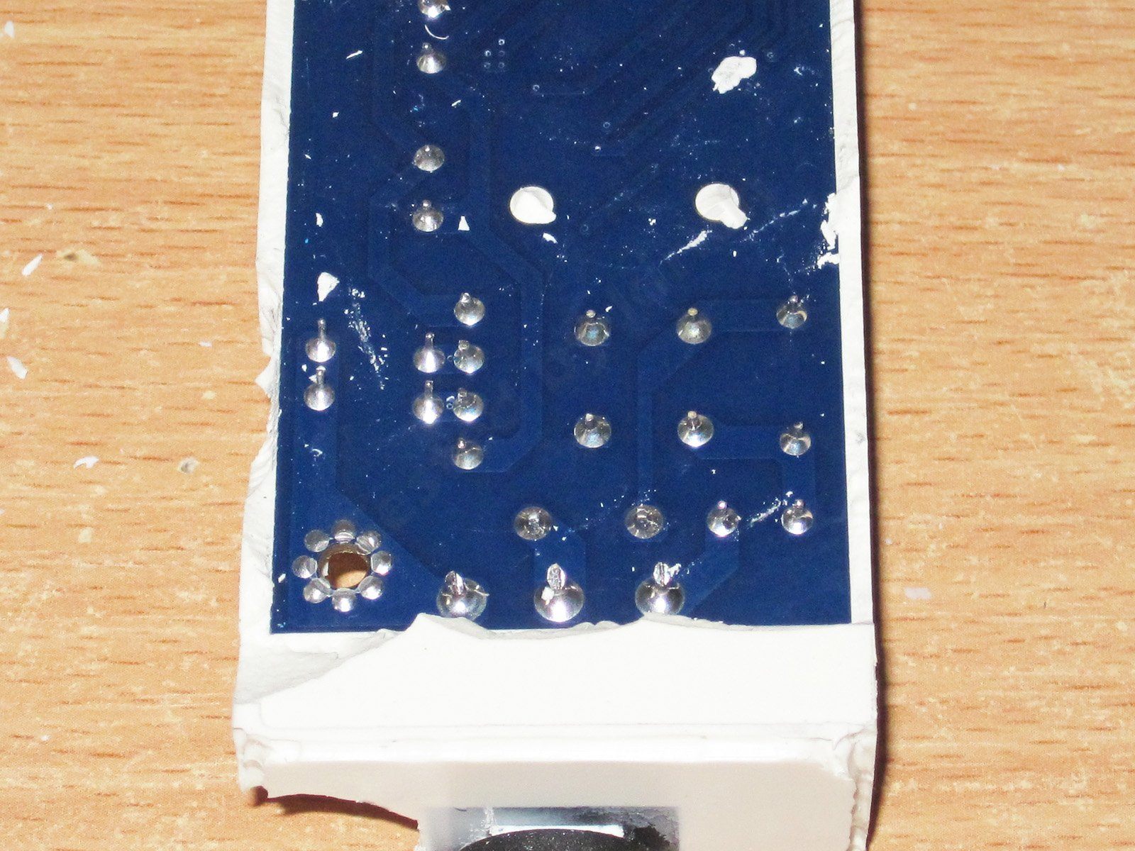
By the way, the board is screwed in rather than just sitting in the case, and the ground wire is connected to that screw as well.

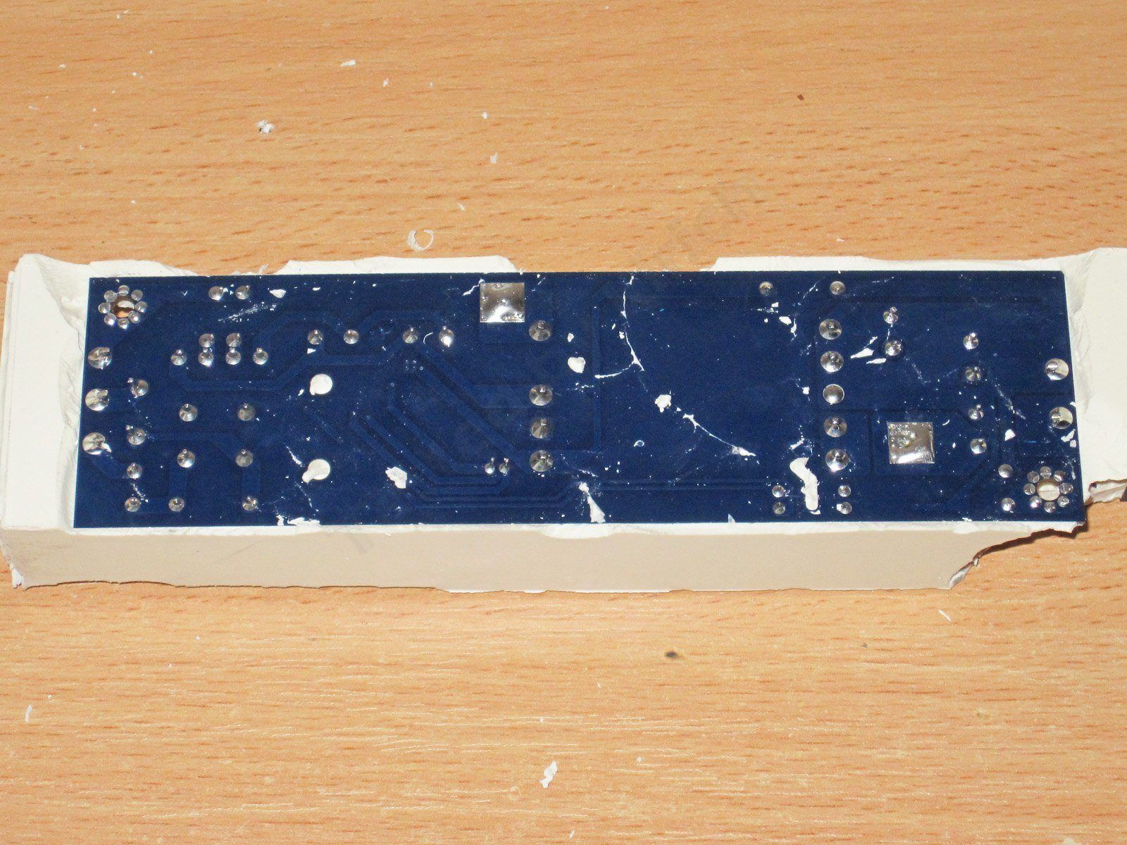
The underside of the board is neat, and I have no complaints about the clearance between the primary and secondary sides either.

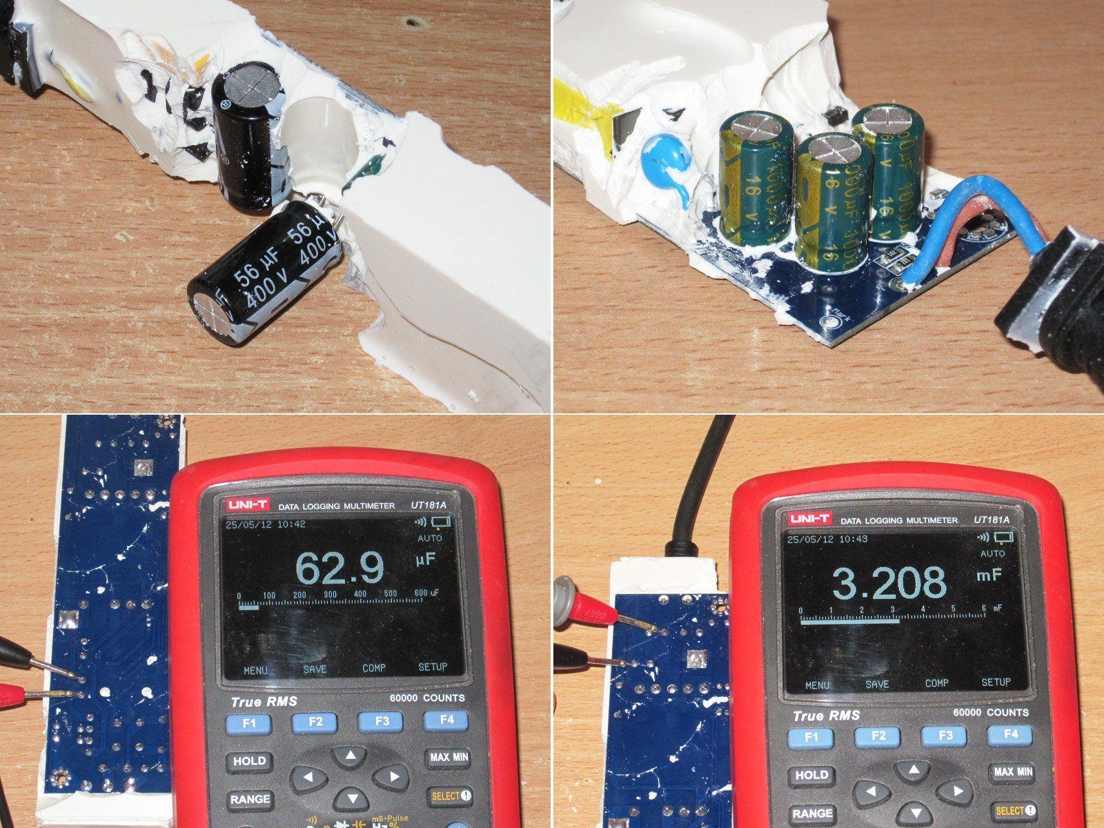
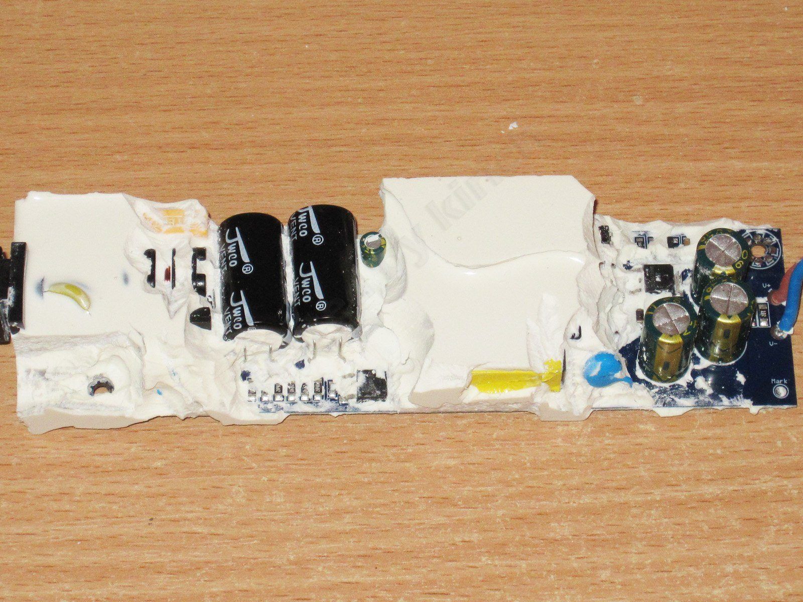
There are two 56 µF input capacitors and three 1000 µF, 16 V output capacitors.
The actual capacitance of the input capacitors is noticeably lower, at around 33 µF, while the output capacitance is as specified.
I think the engineers specified the right input capacitors, but whoever buys components for the factory decided to cut costs and bought some kind of counterfeit. Still, this capacitance is enough for 60 W at 230 V.

The input section layout shows a fuse, thermistor, inductor, X capacitor, and a pair of Y capacitors—in other words, an almost complete input filter, which is nice.

I decided to stop disassembling it at this point. I could have dug around some more, of course, but I’d got the information I needed and didn’t see any point in cleaning the board further.

Conclusions.
As usual, I’ll go through the models one by one.
10 W: A very good power supply. Being able to sustain almost twice its rated power for an extended period without the voltage drifting is fantastic. The ripple could be a little lower, though that’s secondary. The main issue is that its overcurrent protection is set far too high. I’d recommend lowering the threshold by about half, or at least by a third. Otherwise, I liked it.
24 W: This one was probably my favorite. It has decent output capacitance, relatively low ripple, and plenty of power headroom. It sustained 125% of its rated power for an extended period, and the protection is set up reasonably well. Overall, very good indeed.
36 W: A slightly odd power supply. On the one hand, it easily handles its rated power; on the other, the protection threshold is set almost right at the limit. The output capacitance is just 1000 µF, which means higher ripple in the short term and a shorter output capacitor lifespan in the long run. Personally, I’d either leave the protection current as is or raise it by about 10%. And the output capacitance should be at least 2200 µF, preferably 3 × 1000 µF. Then it would be a good, reliable power supply.
50 W: Unfortunately, it dropped out of the race too early. I did like its construction, though. Inside, it’s a proper board, if a bit small; there’s no filter, and the safety clearance is a little tight, but overall it’s perfectly fine if the price is low. The overcurrent protection is set very incorrectly, which is a major drawback. It needs to be lowered by at least a third, if not more, and then it would be a reasonably good power supply. Actually, no—the 2200 µF output capacitance is also a bit low. Looking inside gives some reason to think the other three power supplies are built similarly, but experience with Chinese power supplies tells me that may not be the case.
100 W: Here, they’ve effectively limited the power to 60 W right from the start. But the power supply has acceptable ripple, operates stably at this power on both 230 V and 115 V input, and its safety is fine too. Overall, if we consider it a 60 W power supply, it’s very good indeed. And given how tightly the output is limited, it would be quite difficult to burn it out: it works reliably up to 60 W, and above 62–65 W the protection simply kicks in.
In short, all the power supplies are interesting in their own way, but, as always, there are “caveats” you need to understand and accept. Meanwhile, we’ll keep looking for good power supplies among the Chinese offerings and giving manufacturers a nudge to make them the way they should be, rather than the way that’s easiest and most convenient for them.
That’s all for today. I hope you found this useful, and thanks to Vitaly for providing the power supplies for review.
A reminder: to keep up with new topics on the blog, I recommend following me on Instagram, where I'll post notifications about all new topics and maybe write about something interesting too - link to my account
You can also subscribe to updates and new articles on the Telegram channel - https://t.me/KirichBlog
Since these power supplies are sealed, their descriptions will be much simpler and will mostly consist of tests and some conclusions based on them.
First, the main players: four slim power supplies, well suited for all kinds of built-in applications in light fixtures, LED signs, and more.
I'll start with the smallest model, rated at 12 V and 10 W. Yes, it's a little guy like this, though “little” is relative.
The case is made from an aluminum extrusion, with plastic end caps and the internals potted in compound. There is a small window under the label, though, through which you can get a glimpse inside.
The case measures 96(115) x 29 x 20 mm.
It's very awkward to measure the input capacitor's capacitance, but the output capacitor is easy to access, and its capacitance is clearly around 470 µF, which is quite enough for a power supply like this.
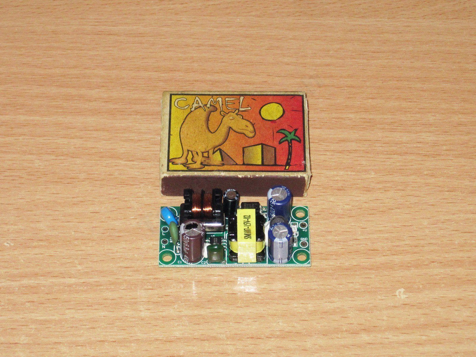
Why did I say the power supply is “relatively” small? Because I often use power supplies made by Sanmim. For example, here's a 6 W power supply that can actually deliver 9 W continuously, and includes an input inductor, a varistor, and a thermistor. It also has two capacitors and an inductor on the output, i.e. a filter to reduce ripple. I think if you put a board like that in a metal case and pot it, it could deliver 10 W too :) And here's a 12 W power supply from the same manufacturer, which can also run at a higher power.
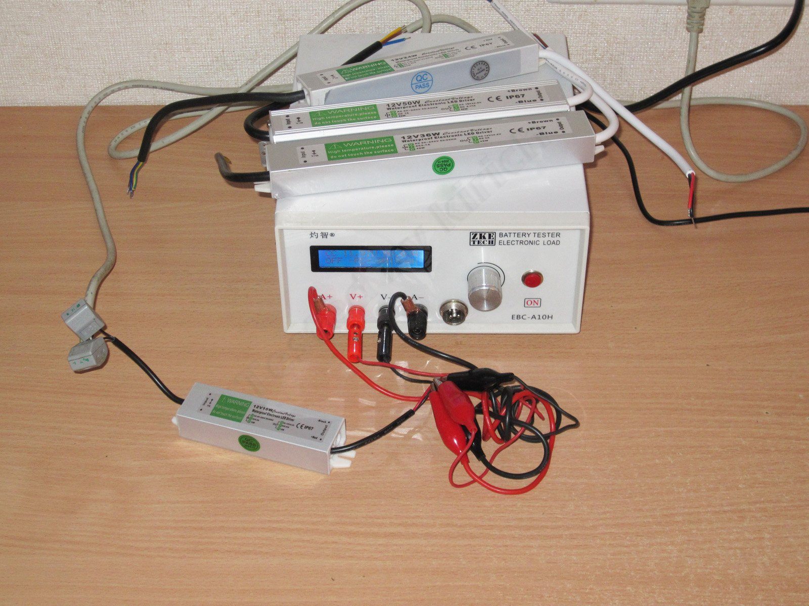
I used a ZKEtech EBC-A10H battery tester for measurements and testing; it's more convenient for plotting graphs.
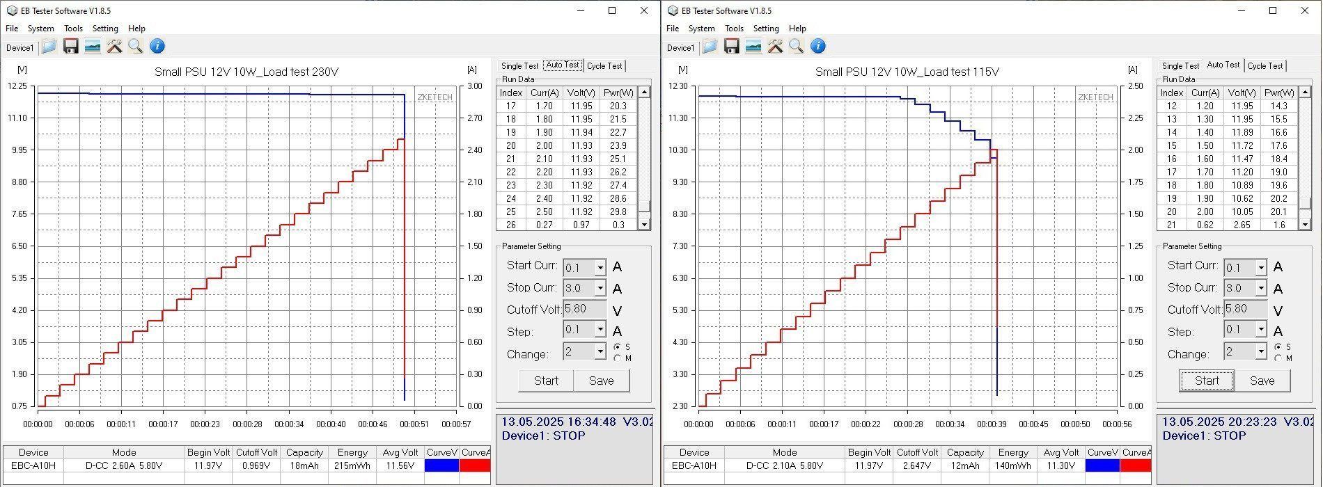
The tests will be roughly the same for all the models. First up is a test to find the overload protection trip point. I tested with input voltages of 230 and 115 V.
And here I have to say I wasn't happy with the results. At 230 V, the power supply shut down at a current above 2.5 A; at 115 V, it shut down above 2 A. So in practice, that's about 2–3 times the rated value.
That's not great, because you can load the power supply well beyond its rated power and it will fail simply from overheating, without the protection even making a peep. In my opinion, the protection trip point should be around 20–25% above the rated power, 50% at most, and at least 10% to avoid false trips. In any case, it should never exceed the level at which the power supply can operate reliably over the long term. The protection threshold also depends heavily on both the power supply's rating and the type of load.
One thing is somewhat reassuring: the protection has a threshold, and at 115 V the trip point is noticeably lower than at 230 V. In terms of power, the difference is as much as a factor of one and a half.
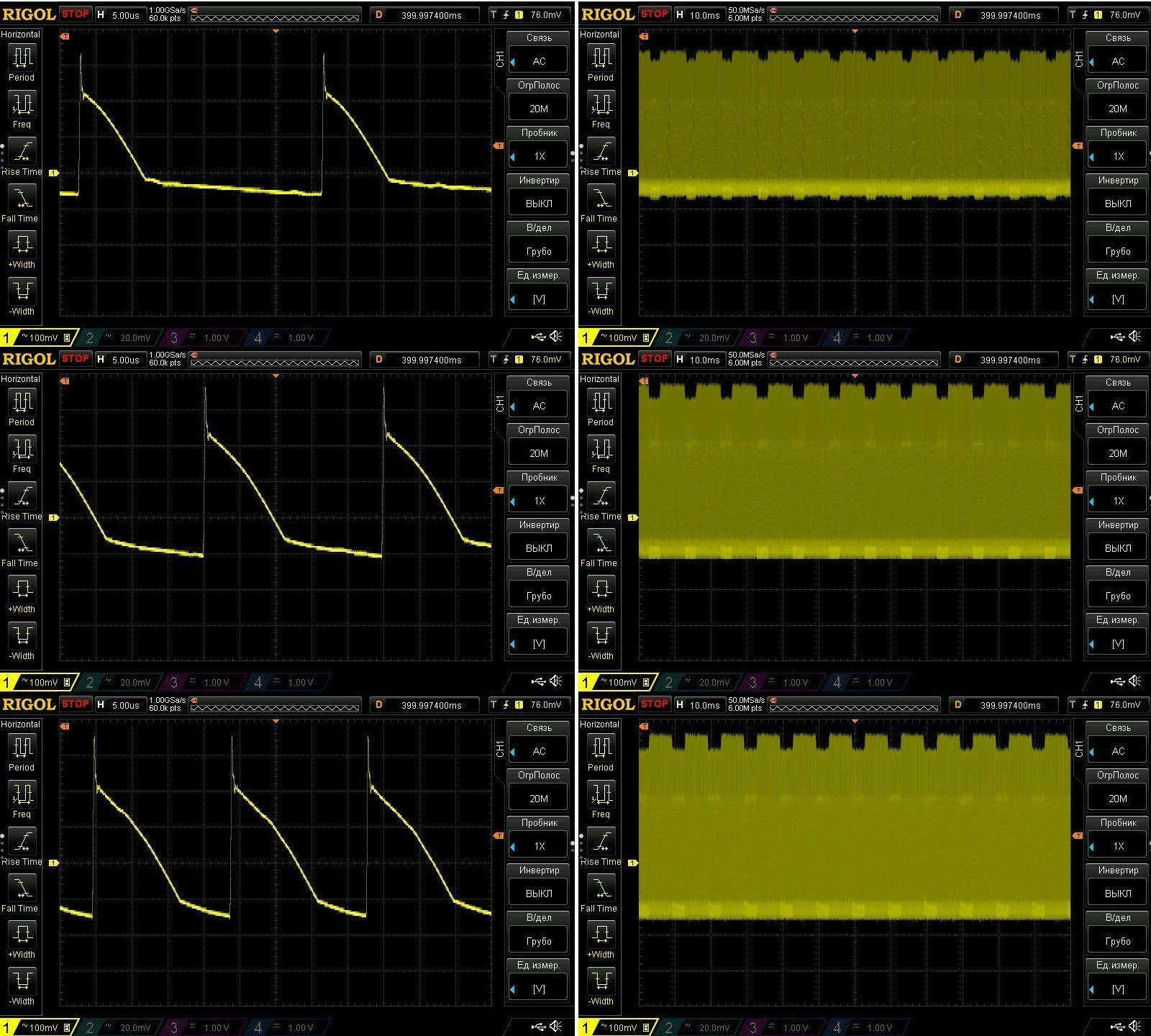
Test two: assessing the output ripple level. As usual, I measured two types of ripple: high-frequency and low-frequency.
I tested at load currents of 0.5, 1, and 1.5 A. In fact, even 1 A is a slight overload.
The ripple amplitude is almost independent of the load current and is around 300–400 mV. Unfortunately, that's not very good, but it's still quite adequate for powering all kinds of lights and backlights.
At low frequencies, you can see some spikes at 100 Hz. Interestingly, they have a well-defined shape. In any case, I have no complaints about the low-frequency component.
Load test: I again tested at load currents of 0.5, 1, and 1.5 A, for about 20 minutes at each step.
There are two graphs so we can see what the voltage was initially (the line at the bottom left), what it was at the end of the loaded test (the first graph at the top right), and what it was after removing the load (the second graph at the top right).
For example, this power supply started at 11.98 V. After warming up under load, it was at 11.95 V; after removing the load, it returned to 11.98 V.
That is, In practice, we have zero voltage dependence on temperature and only minimal dependence on load current—an ideal result, especially considering the nearly twofold overload.
Case temperature after testing at 0.5, 1 and 1.5 A. A piece of electrical tape was stuck to the case to improve measurement accuracy.
It's hard to judge here: the case is warm, but it's impossible to tell whether there are any localized hot spots because the components aren't accessible.
The second power supply, 12 V, 24 W.
Noticeably longer than the previous one: 162(180) × 29 × 20 mm.
The design is identical; the only difference is that the potting compound here is opaque.
Apparently, there's a single 2200 µF capacitor on the output, which is more than enough for a 24 W power supply.
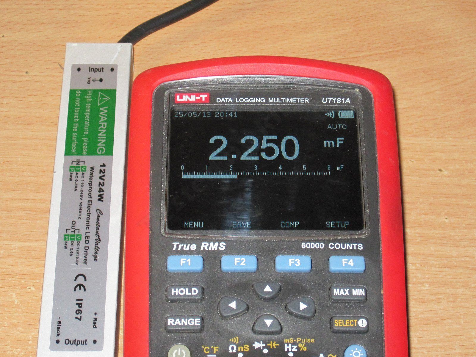
Interestingly, the protection trip current here doesn't depend on the input voltage. The input capacitor may also have a higher capacitance.
The protection trips at around 3 A, or roughly 50% above the maximum current, which is within the acceptable upper limit.
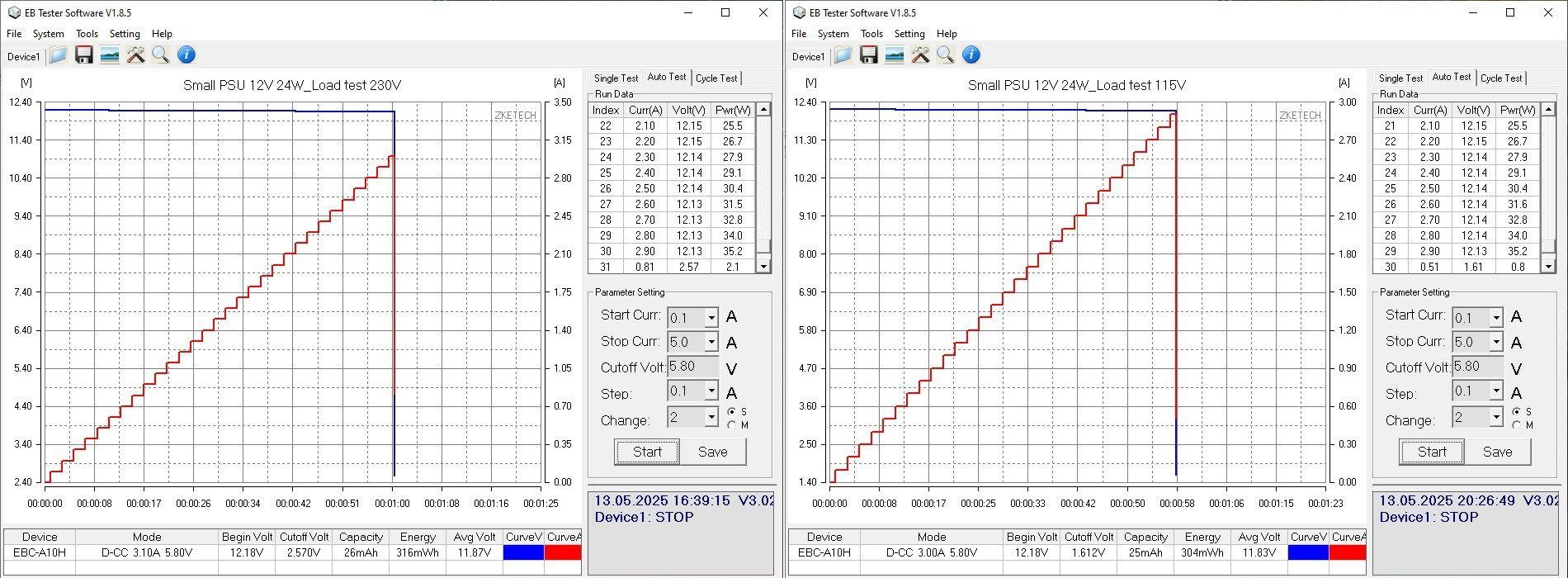
Ripple was measured at load currents of 1, 2 and 2.5 A, i.e. at up to 125% load.
And I have to say, the results are pretty good. Even at maximum load, the peak-to-peak ripple is around 200–250 mV. The low-frequency component is also fairly small, which indirectly suggests that the input capacitor has sufficient capacitance.
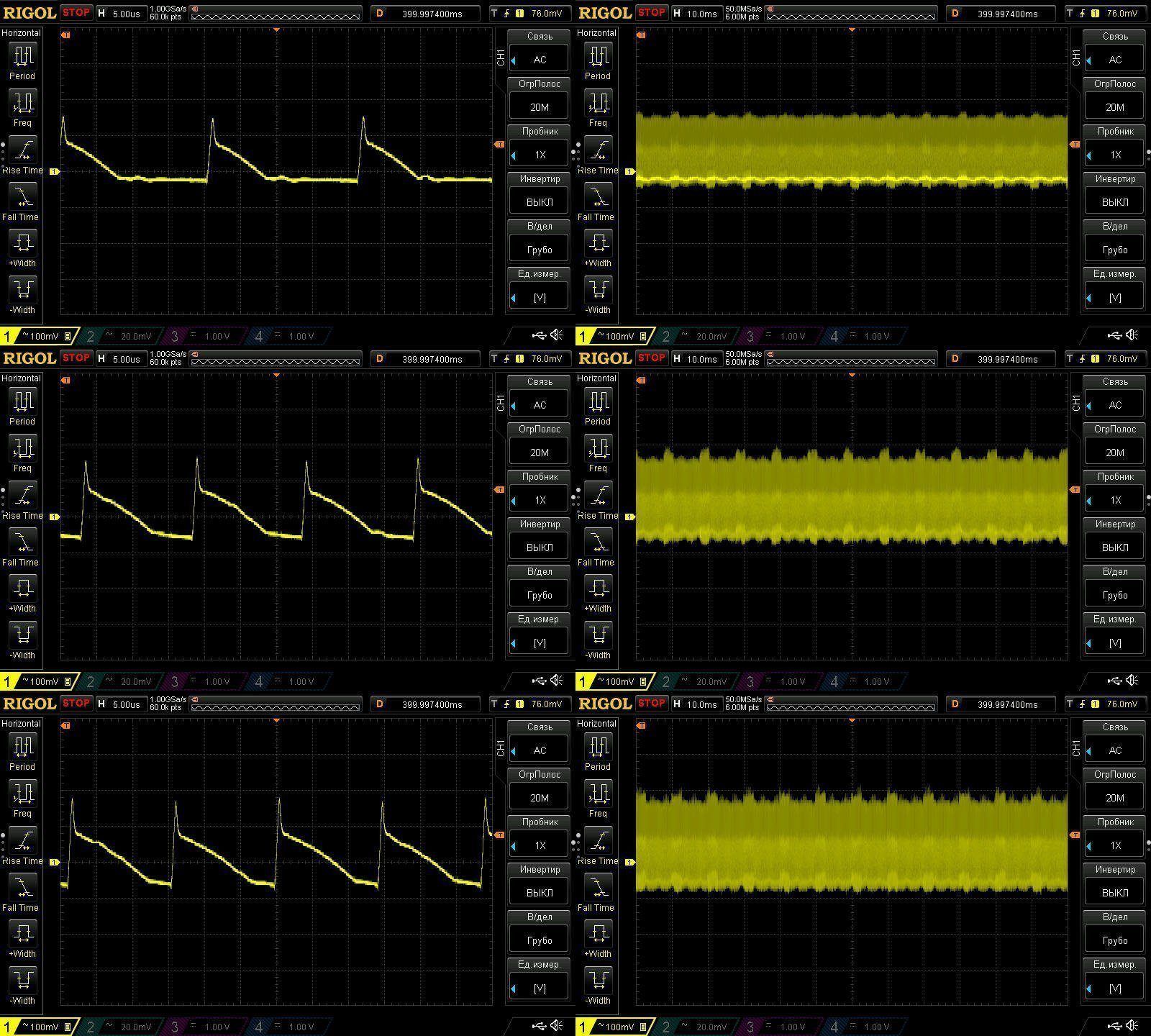
This test was run at 1, 2 and 2.5 A, with the same intervals of about 20 minutes each.
At the start of the test, the voltage was 12.19 V; hot under 125% load, 12.13 V; and with no load, 12.16 V. Practically perfect.
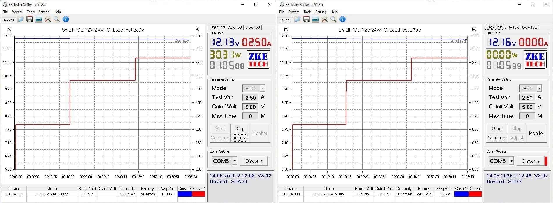
The case temperature is also fine.
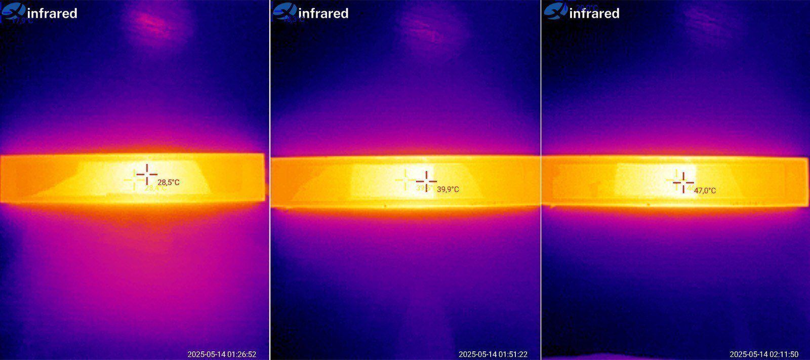
The third model, 12 V, 36 W.
The case measures 201(221) × 29 × 20 mm; the only difference from the previous models is the length.
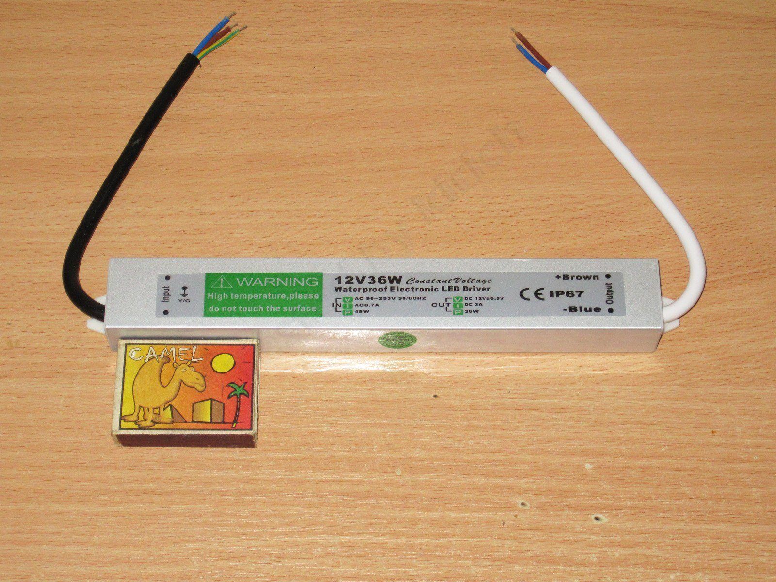
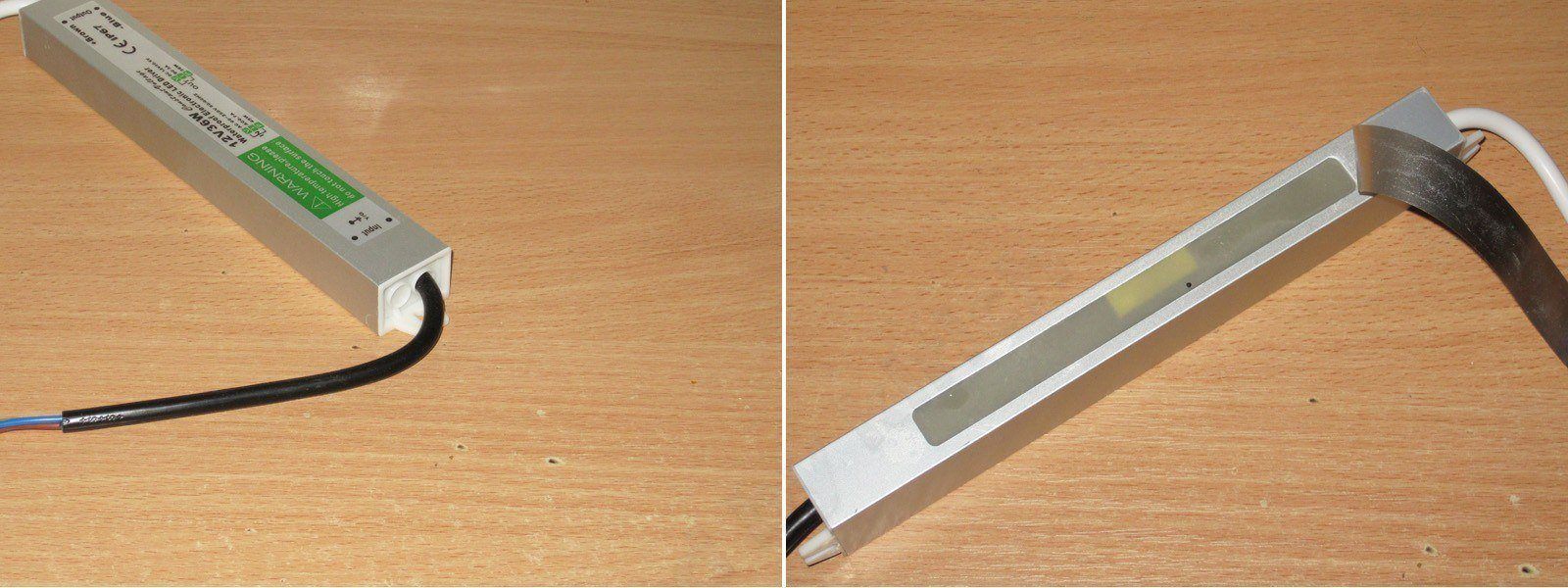
The design is similar to the previous models. You can just about see the transformer through the window; it's larger than the one in the 10 W version.
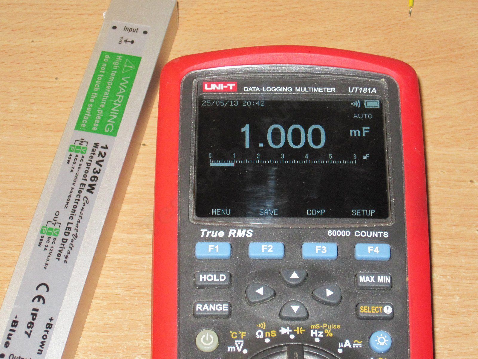
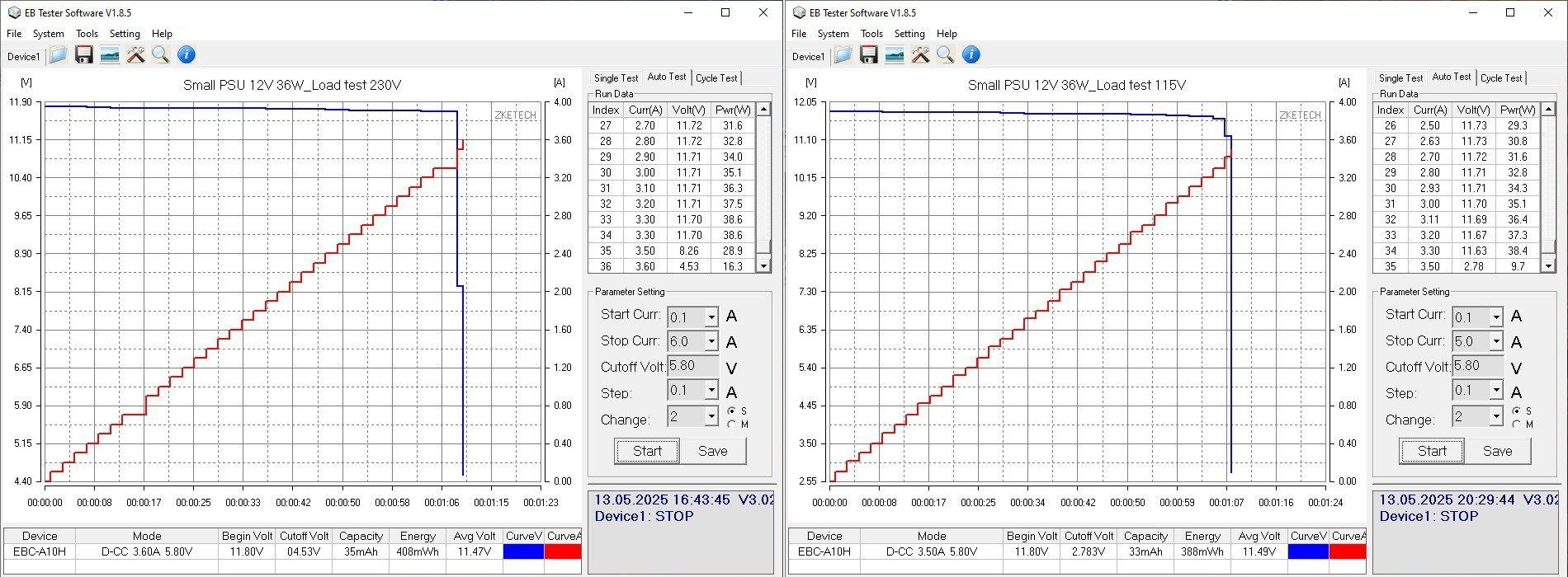
The 1000 µF output capacitance left me puzzled. The 10 W model had 470 µF, the 24 W model had 2200 µF, and this one has just 1000...
The protection trips at roughly the same current, 3.4 A, at both 230 and 115 V. The only difference is that at 115 V, the voltage started to drop noticeably before the protection kicked in.
In any case, the trip threshold is about 10–15% above the maximum current, which is actually pretty good.
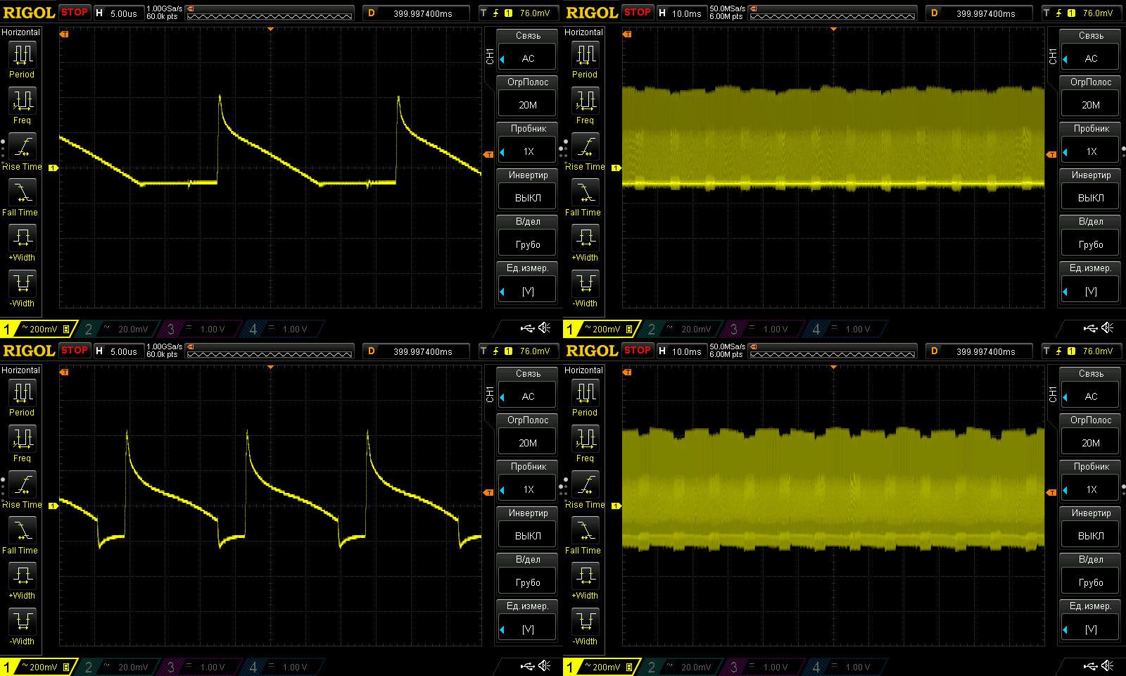
Since the protection threshold is very close to the maximum current, I checked ripple at 1.5 and 3 A.
Well, it's clear that 1000 µF isn't enough here: the high-frequency ripple is around 400–600 mV peak-to-peak, while the low-frequency ripple isn't that large. The input capacitance may be relatively high; the similar protection trip thresholds at 230 and 115 V also point to this.
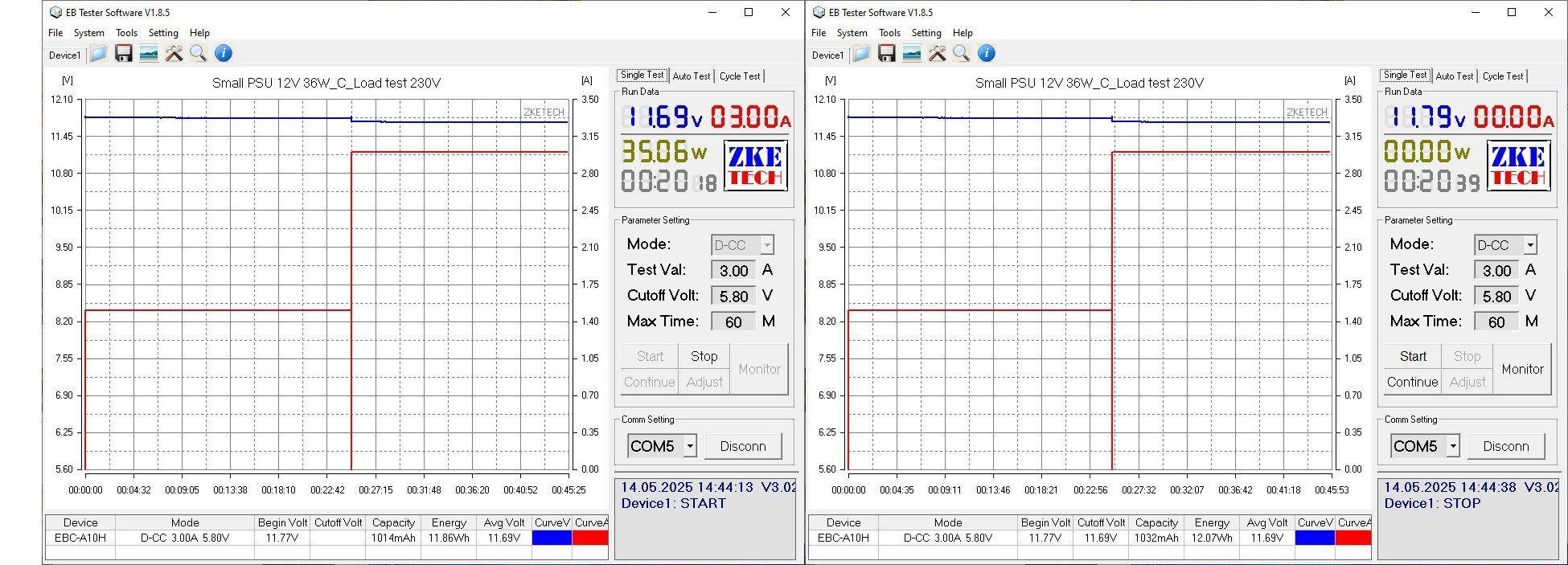
The temperature test was run at 1.5 and 3 A. I had to repeat the test to check how the voltage changed; each stage actually lasted about 20–25 minutes.
The initial voltage was 11.77 V; warmed up under full load, 11.69 V; warmed up with no load, 11.79 V. Results close to ideal.
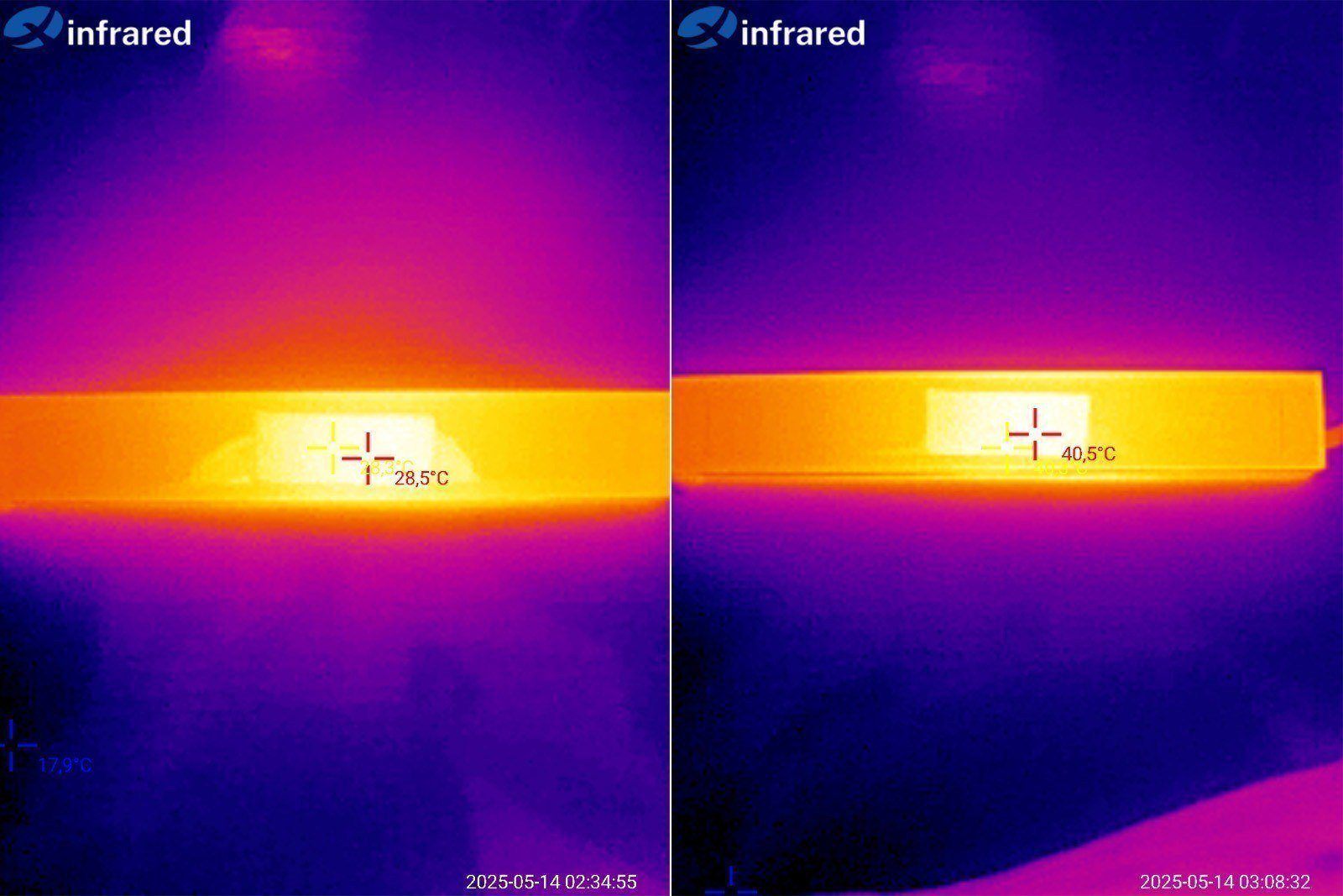
I also had no complaints about the case temperature, although there are three possibilities here:
1. Bad: the potting compound has poor thermal conductivity, so the components are actually much hotter.
2. Good: the power supply is efficient, so it generates little heat.
3. In between: the case is simply large, so the heat is distributed well.
I hope it's at least the third option.
The fourth power supply, 12 V, 50 W.
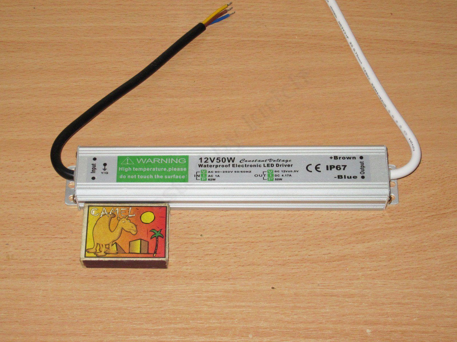
The design differs slightly in both the case profile and its dimensions: 185(205) × 34 × 23 mm. You can see that the case is shorter than the 36 W version, but wider and thicker, and it also has extra fins, which is very useful.
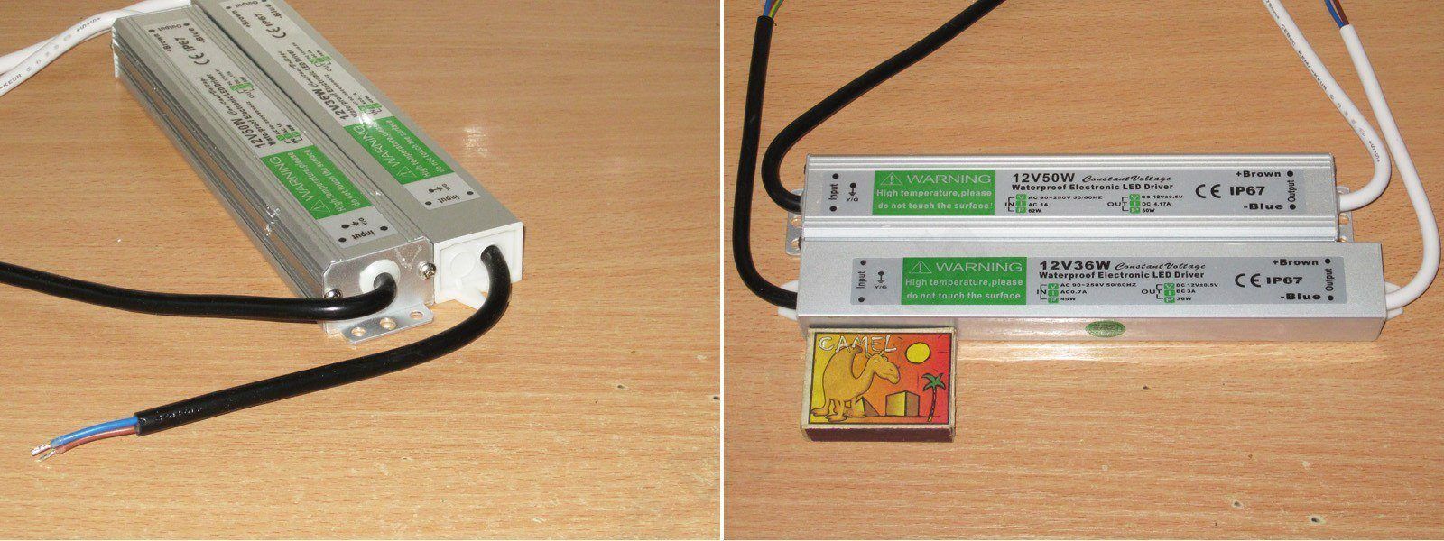
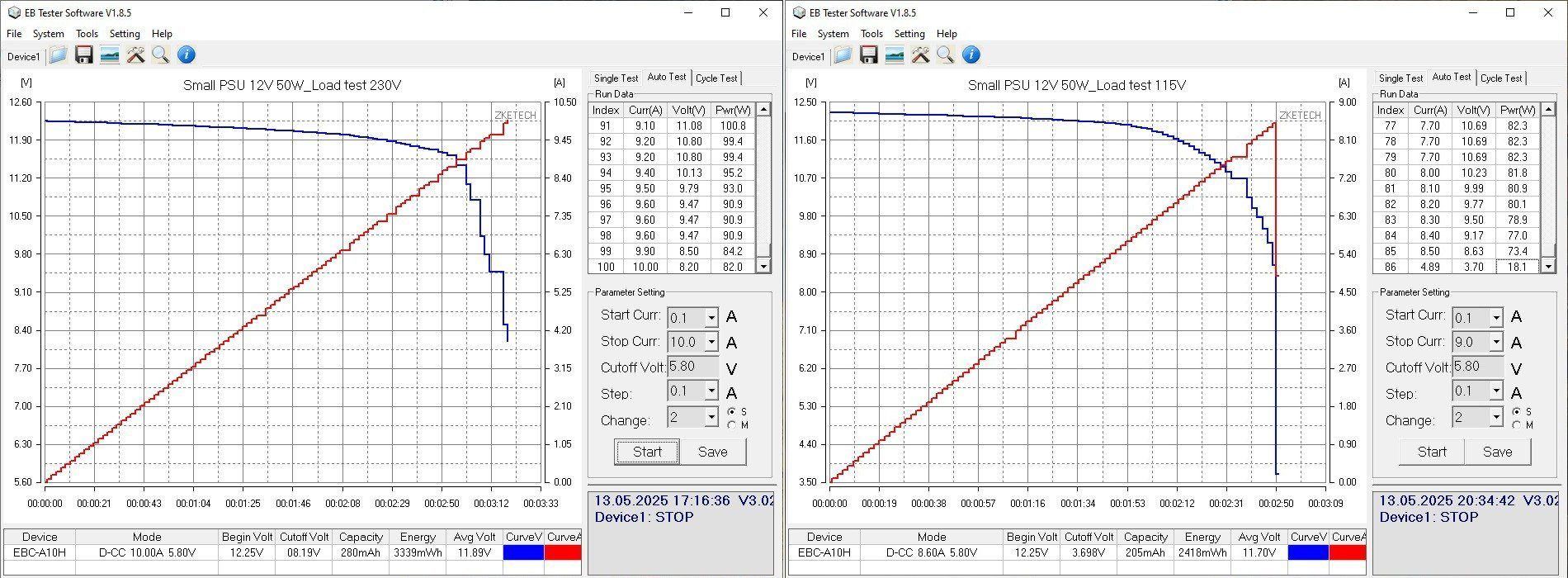
The output capacitance is 2200 µF, just about enough for the rated specs.
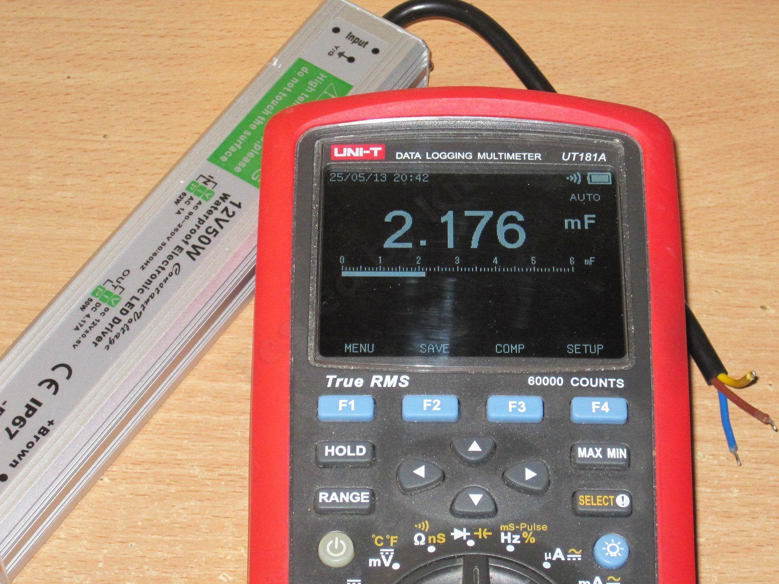
The load graph shows that the protection threshold is set much too high. It also clearly uses a different controller, since the voltage drops gradually at the end. In other words, the power supply has essentially switched to power limiting, reaching about 100 W despite being rated for 50 W. That's far too much.
But there's a worse problem: during a test at 115 V, the power supply failed. At first it went quietly, but when I tried applying 230 V, there was a bang, a little smoke, and a black streak of soot on the table.
What a shame. I really should have run this test last. To be fair, though, this is the first power supply I've had die during a test like this.
This is also a clear example of why you shouldn't set the protection threshold too high.
But even a burnt-out power supply can be useful: you can take it apart and see what's inside. Now I definitely don't mind poking around in it :)
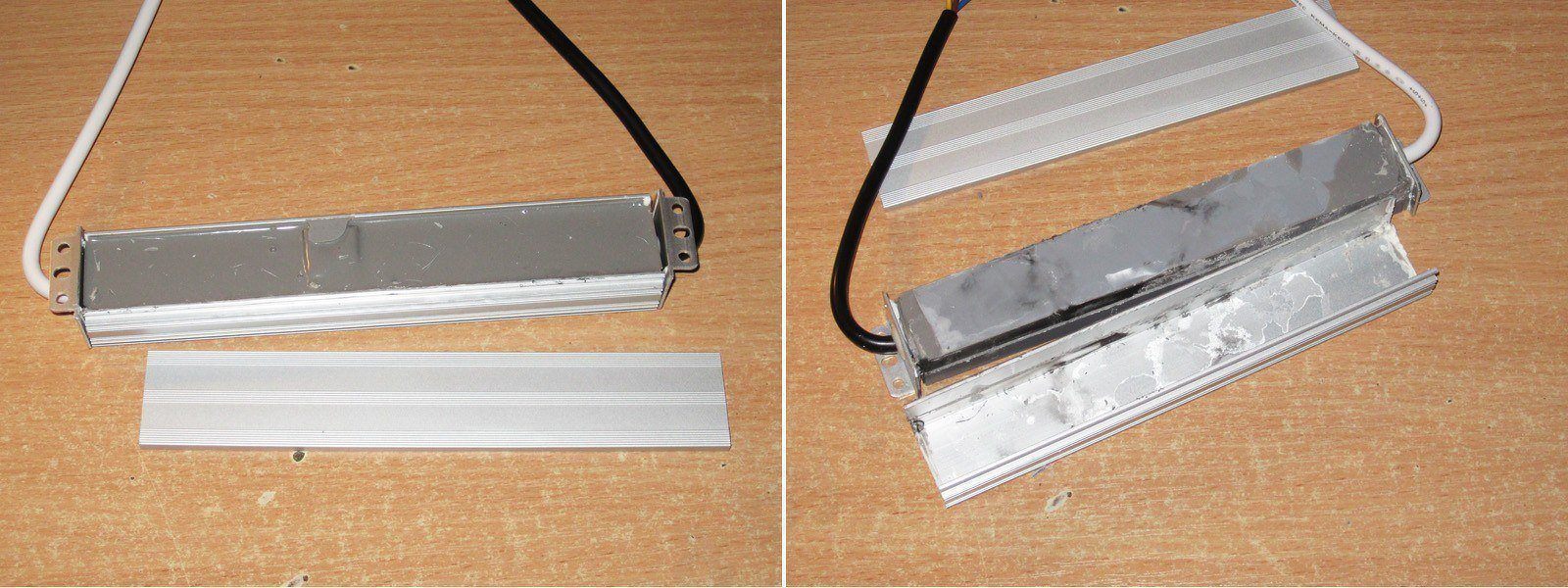
After a while with tweezers, a knife, and a few other tools, we get a look inside.
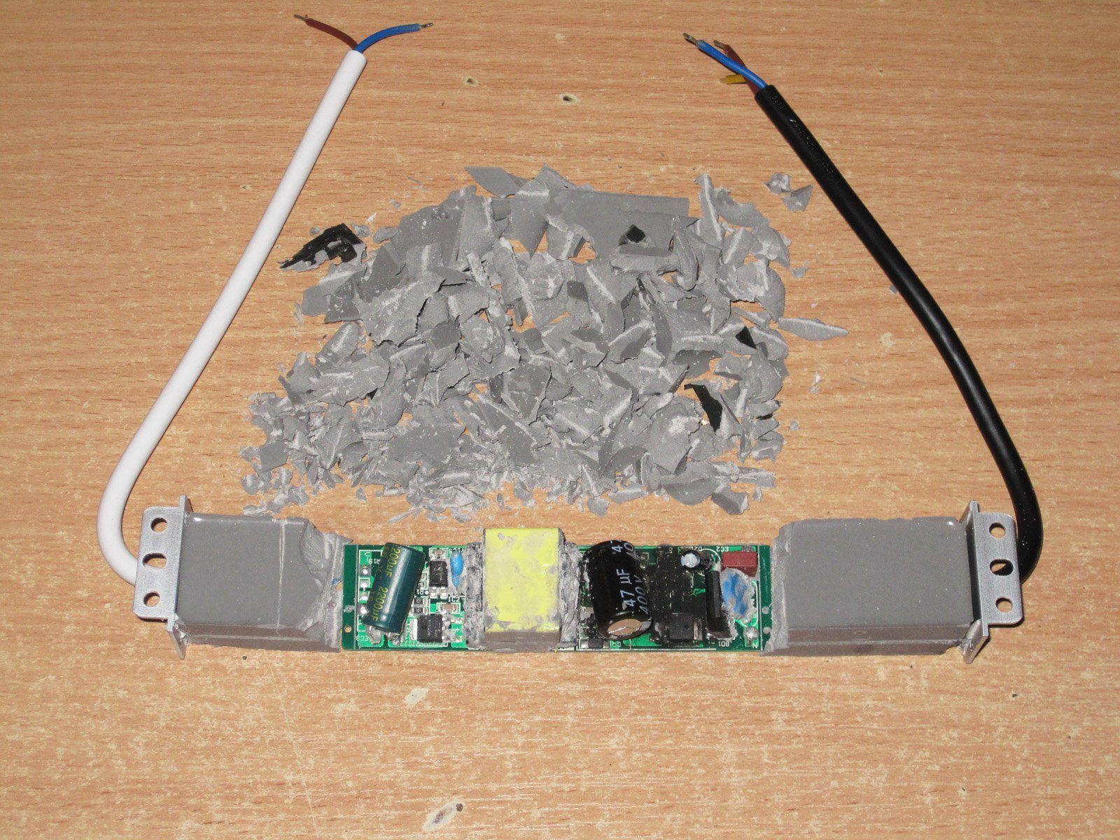
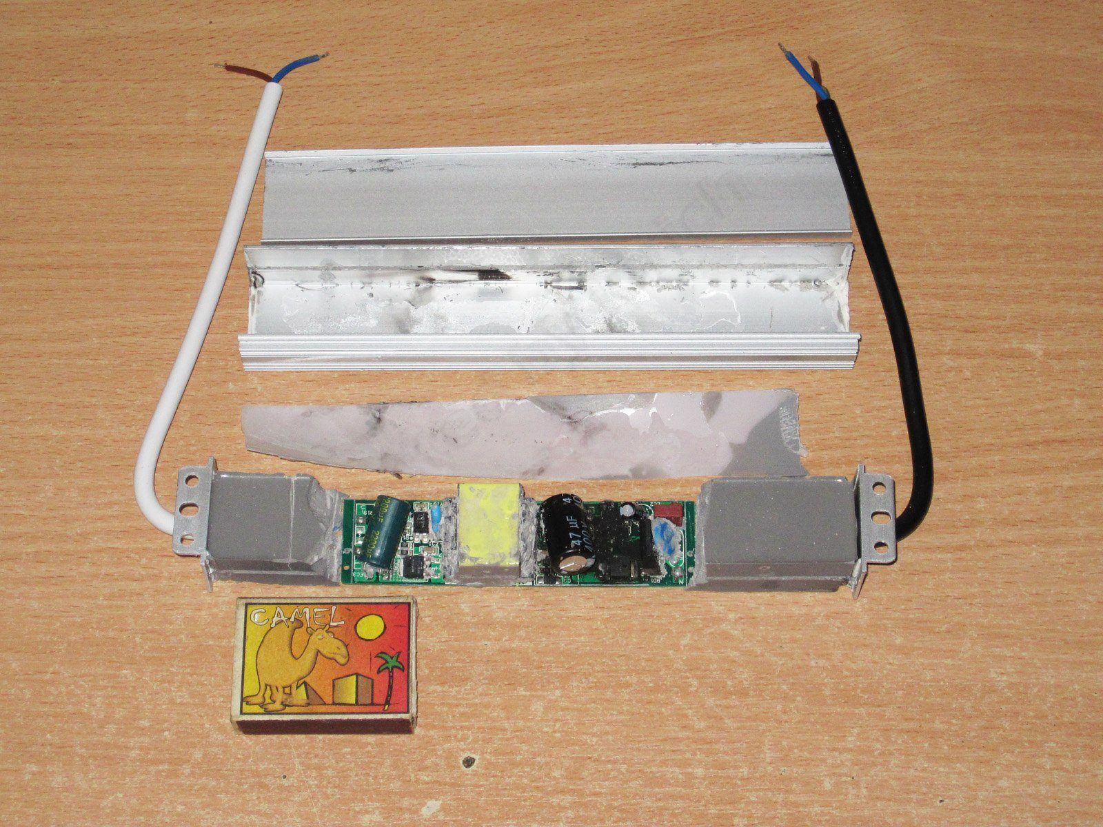
There was an insulating pad inside, too. Nice. But the first thing I noticed was how small the circuit board is. It takes up just over half the case; the rest is just potting compound and wires.
Interestingly, the potting compound inside is gray, while the end caps were white. Most likely, they filled it with compound and fitted the end caps at a different stage.
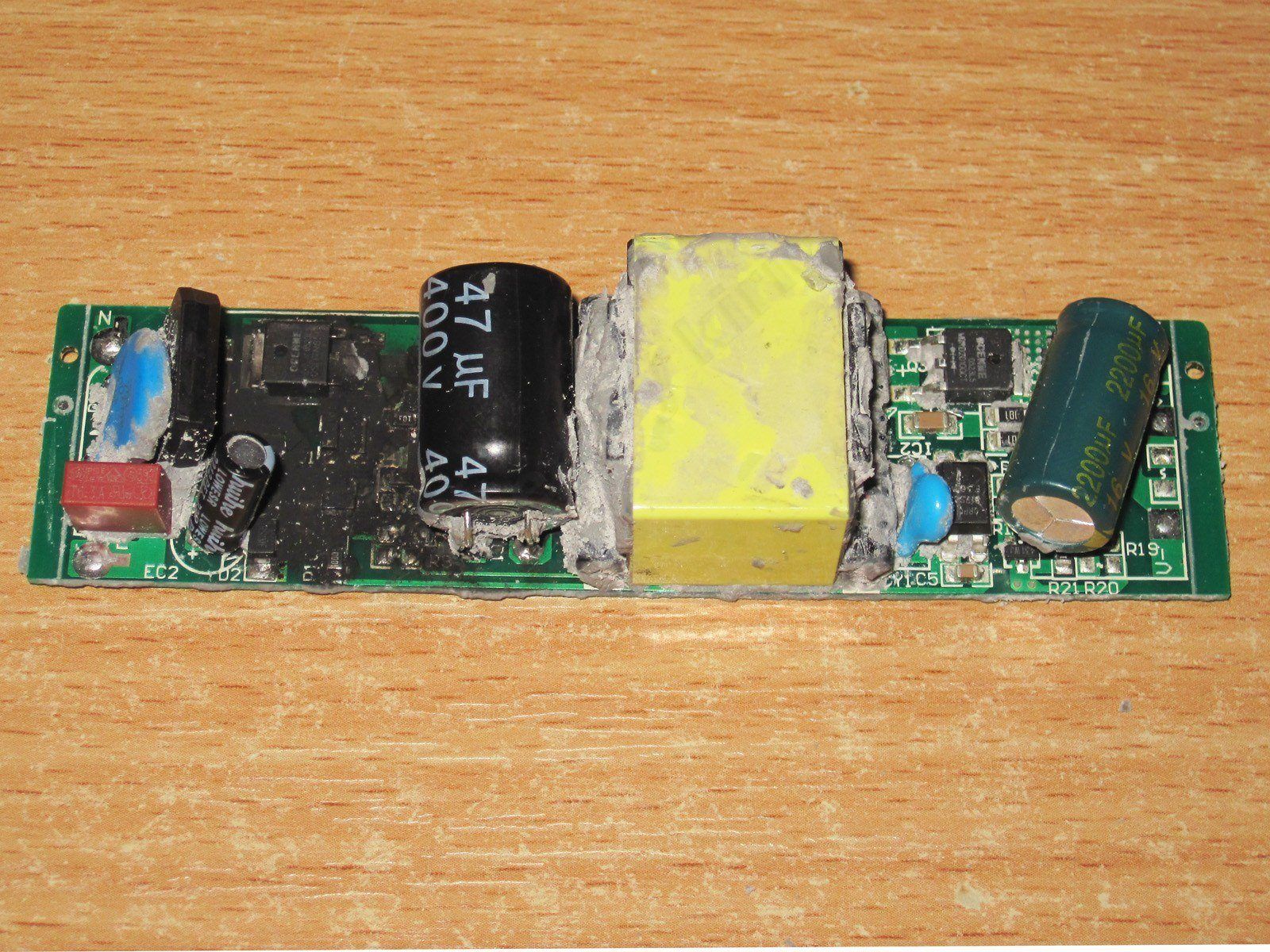
The circuit board really is quite small. There's no input filter, and no output filter either. And as you can see, there are soot marks; it looks like part of the board simply burned out.
The underside is simple and neat. I do have one question about electrical safety: what idiot put a copper pour from the transformer so close to a trace on the hot side? There's plenty of room to provide a decent clearance here, but for some reason they made it smaller. The only thing that helps at all is that the board is potted.
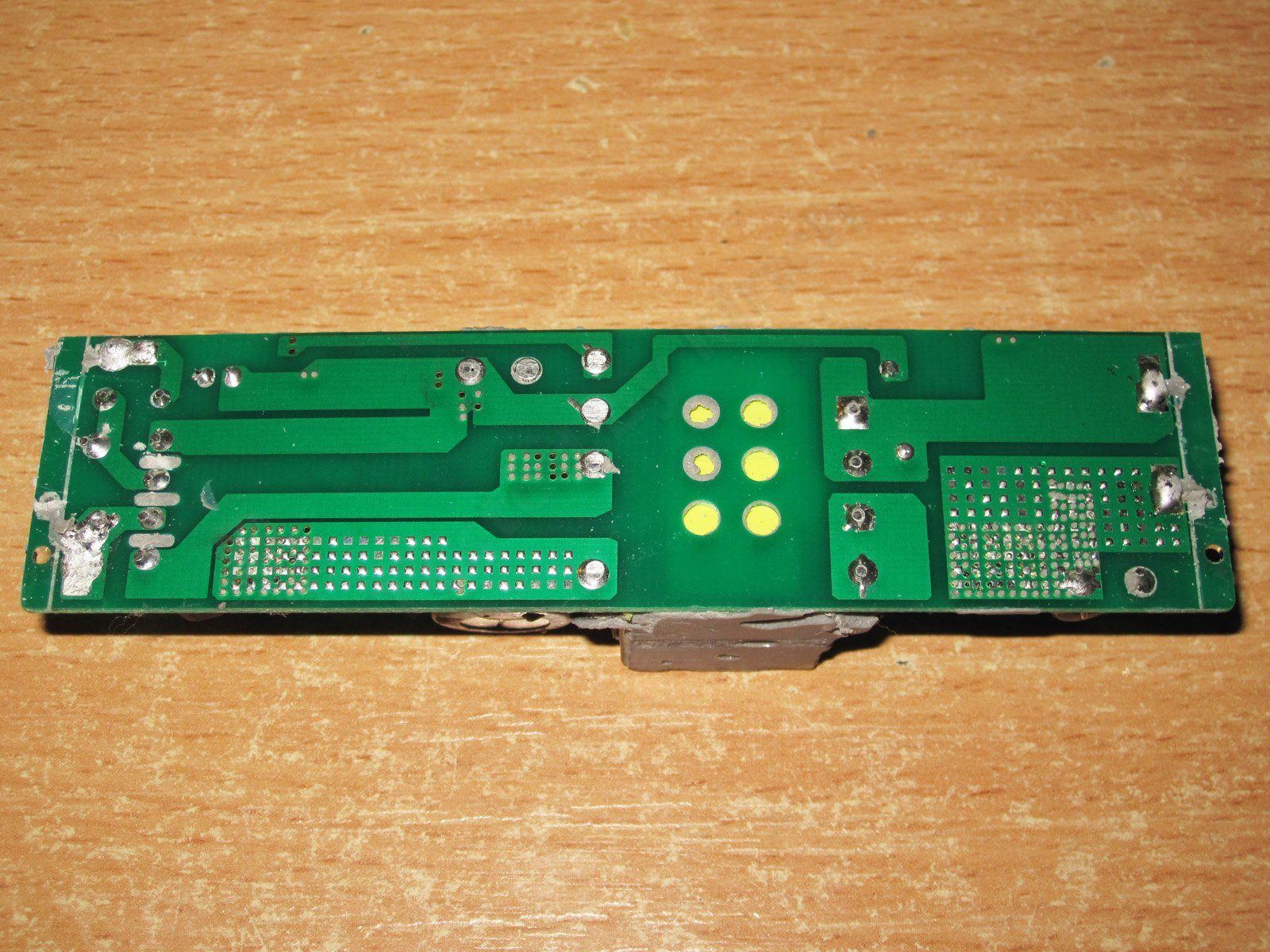
Even trimming the copper pour along the line would make things noticeably better. Though I didn't look too closely at what's on the other side of the board.
1. There's a varistor on the input, which is a nice and unexpected touch. The input capacitor is 47 µF, which is basically fine for a 50 W power supply running from 230 V, but a bit small for 115 V. Still, that's typical of Chinese power supplies.
2. The actual capacitance is slightly lower, but within tolerance.
3. The interwinding capacitor is the right type, though the markings are hard to read.
4. The output capacitor is rated for 16 V and 2200 µF, just as I measured above.

1, 2. Grab some cotton and alcohol and clean the board. Well, the damage isn't actually that bad, and the board could probably be repaired, but honestly, I can't be bothered.
3. The transistor is rated for 7 A and 65 V, which is perfectly fine for such a small power supply.
4. The output rectifier assembly is rated for 20 A and 100 V. It's unusual to see those specs in such a small package, but they're probably there to reduce the voltage drop, since it's still hard to dissipate much power from a package this size. Either way, that's very good.
My guess is that the transistor failed first, but the transformer limited the short-circuit current, so nothing else burned out. Then I connected it directly to 230 V mains, and things went downhill....
The fifth power supply is the FSA-12V 100W, rated for 12 V and 100 W.
This one made it into the article mostly "for company," since there's not much point in giving it its own article. So it's an extra bonus—and you could count the teardown as a bonus too :)
Case dimensions: 165(185) × 53 × 26 mm
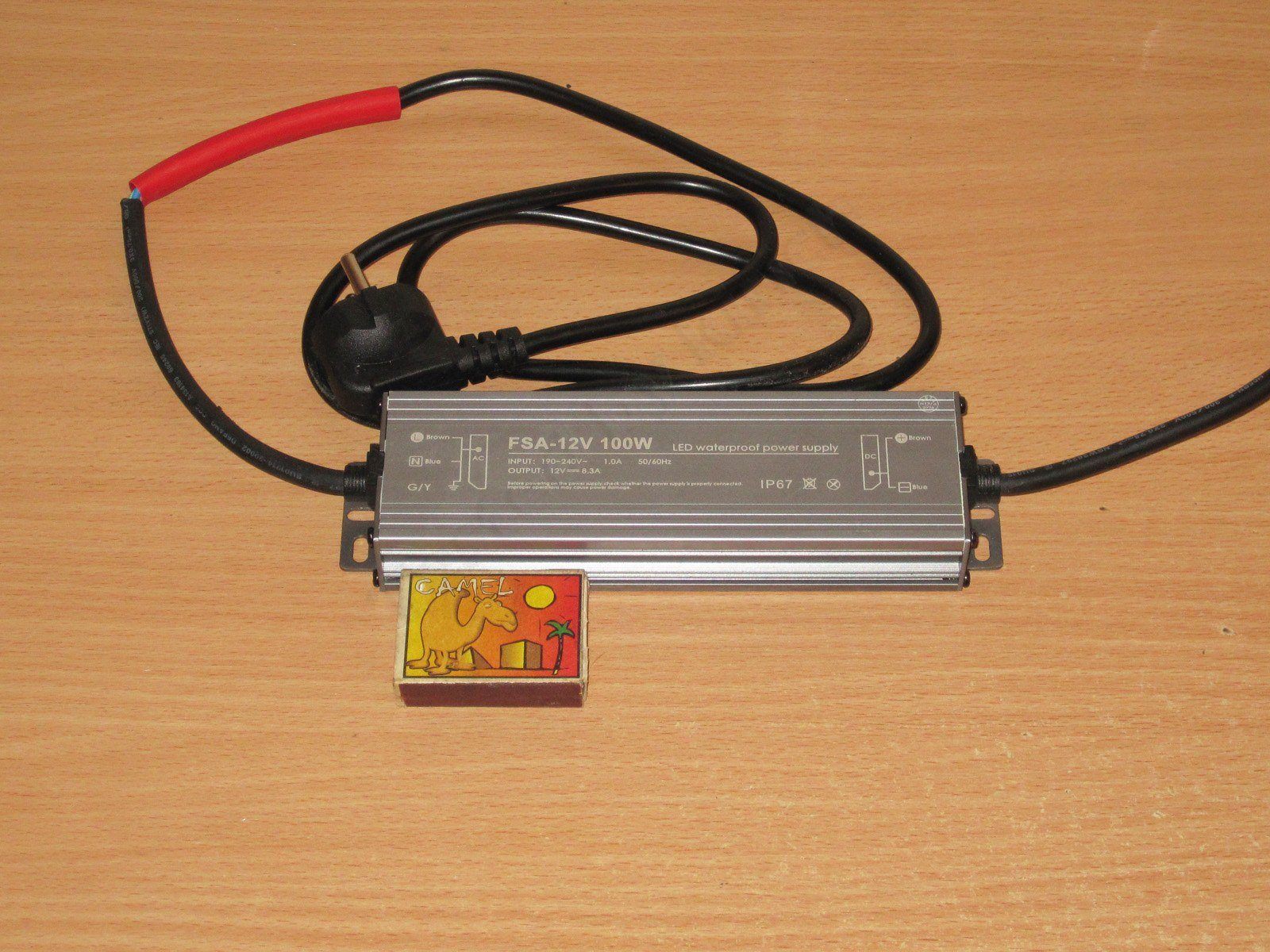
The design is similar to the previous model, but noticeably larger in cross-section. The cable with the plug ended up here by chance and isn't included.
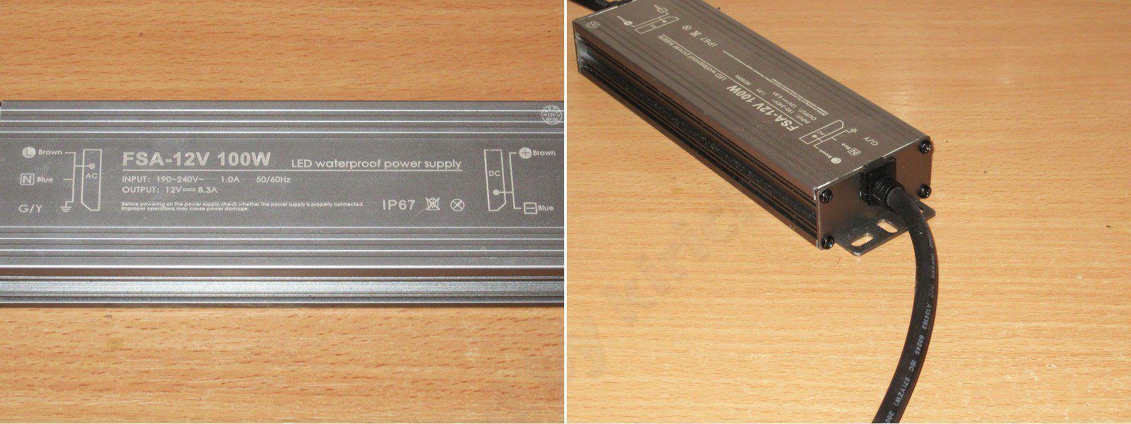
It turned out that the protection is set almost exactly at 60 W—just barely. I'd even say it can handle 50 W with some headroom, but the tests will tell us more about its actual power.

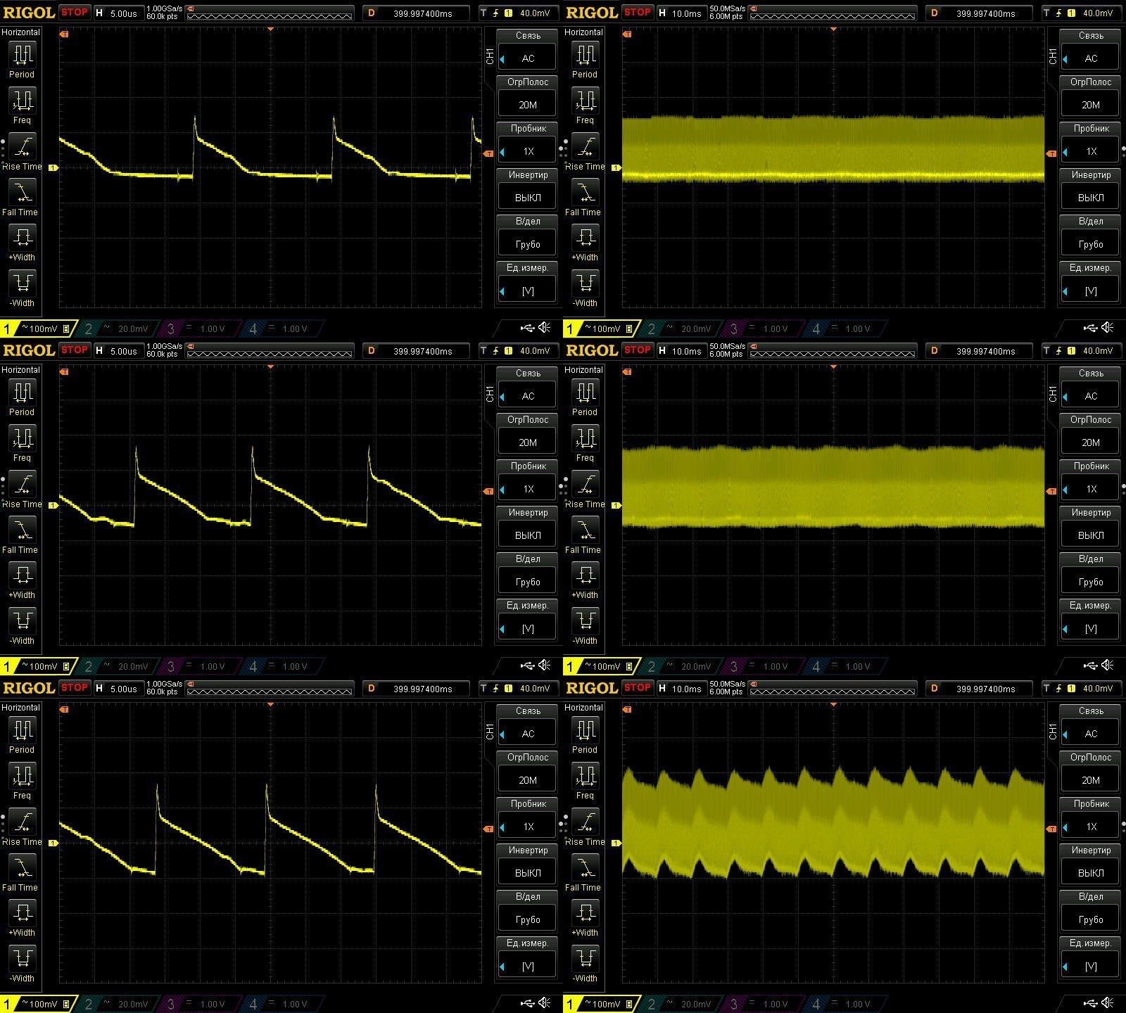
Ripple at currents of 2, 4, and 5.6 A. At high frequencies, things look pretty good here: 150–200 mV is perfectly acceptable.
At low frequencies, though, 100 Hz ripple is clearly showing up at 5.6 A. It’s not exactly critical, but it is noticeable.
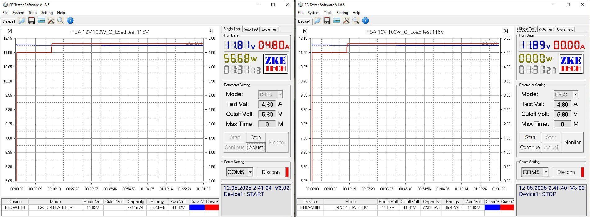
The load test here was run straight at the maximum possible power, about 60 W, for roughly an hour and a half. I tested it the same way at both 230 V and 115 V input; I only ran the previous power supplies under load for an extended period at 230 V.
At the start of the test, the output was 11.89 V. Once warmed up under load, it was 11.81 V. After removing the load, it was back at 11.89 V, just like at the start. Excellent.
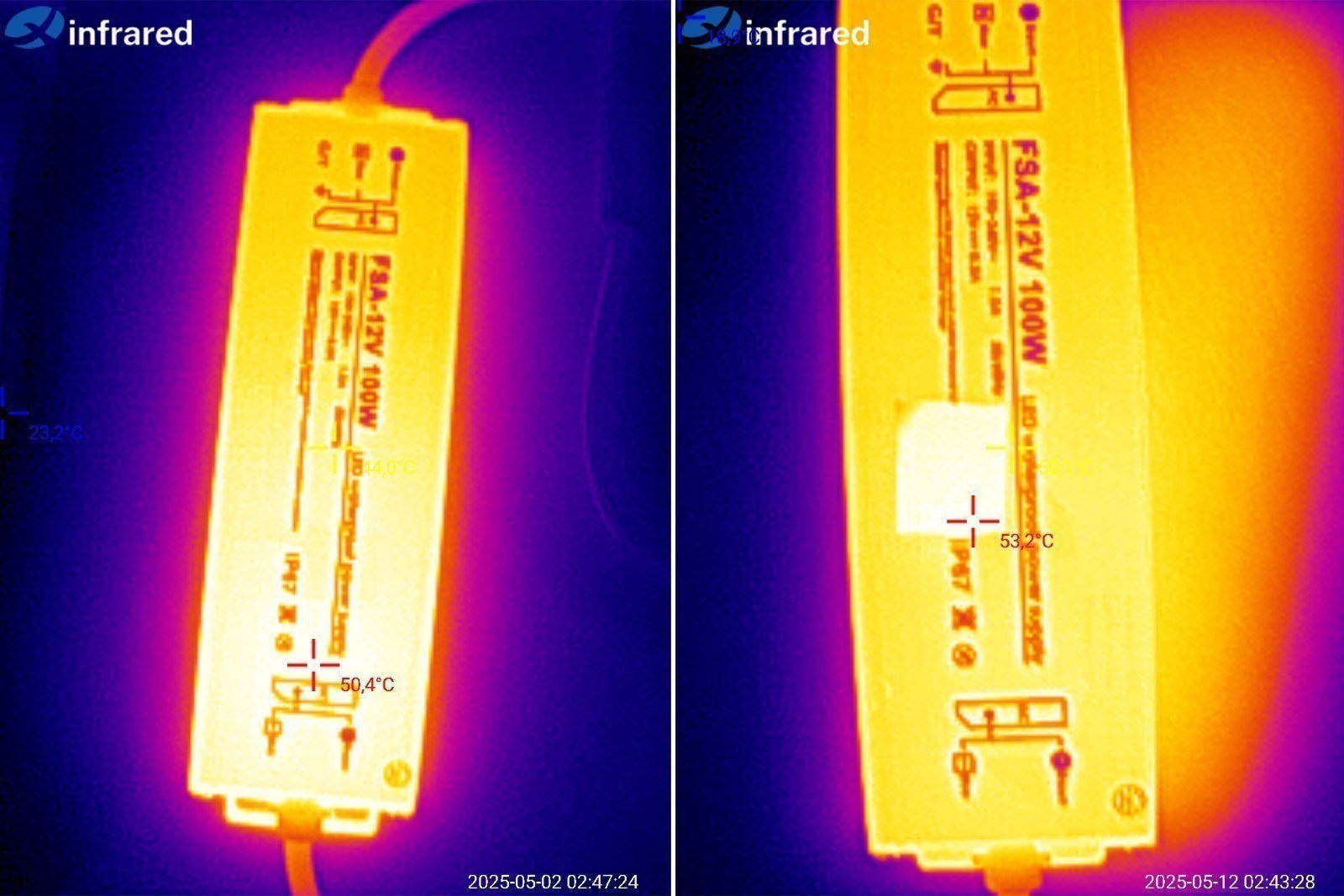
The case temperature was 50°C at 230 V and 53°C at 115 V input, which is also quite good. I even got the impression that this was originally a 100 W power supply, later limited to 60 W. Though I think it would get pretty hot at 100 W.
Don’t worry, nothing burned out. I’m taking the power supply apart as planned; the person who sent it to me asked me to do so for a rough look at its internals.
It’s thoroughly potted, no complaints there.
But what can stop someone who wants to see what’s inside? :) Actually, I got lucky that power supplies like this are potted with relatively soft compounds. When you dig into industrial equipment, you can run into stuff like epoxy resin, and then you’re in trouble...
By the way, the board is screwed in rather than just sitting in the case, and the ground wire is connected to that screw as well.
The underside of the board is neat, and I have no complaints about the clearance between the primary and secondary sides either.
There are two 56 µF input capacitors and three 1000 µF, 16 V output capacitors.
The actual capacitance of the input capacitors is noticeably lower, at around 33 µF, while the output capacitance is as specified.
I think the engineers specified the right input capacitors, but whoever buys components for the factory decided to cut costs and bought some kind of counterfeit. Still, this capacitance is enough for 60 W at 230 V.
The input section layout shows a fuse, thermistor, inductor, X capacitor, and a pair of Y capacitors—in other words, an almost complete input filter, which is nice.
I decided to stop disassembling it at this point. I could have dug around some more, of course, but I’d got the information I needed and didn’t see any point in cleaning the board further.
Conclusions.
As usual, I’ll go through the models one by one.
10 W: A very good power supply. Being able to sustain almost twice its rated power for an extended period without the voltage drifting is fantastic. The ripple could be a little lower, though that’s secondary. The main issue is that its overcurrent protection is set far too high. I’d recommend lowering the threshold by about half, or at least by a third. Otherwise, I liked it.
24 W: This one was probably my favorite. It has decent output capacitance, relatively low ripple, and plenty of power headroom. It sustained 125% of its rated power for an extended period, and the protection is set up reasonably well. Overall, very good indeed.
36 W: A slightly odd power supply. On the one hand, it easily handles its rated power; on the other, the protection threshold is set almost right at the limit. The output capacitance is just 1000 µF, which means higher ripple in the short term and a shorter output capacitor lifespan in the long run. Personally, I’d either leave the protection current as is or raise it by about 10%. And the output capacitance should be at least 2200 µF, preferably 3 × 1000 µF. Then it would be a good, reliable power supply.
50 W: Unfortunately, it dropped out of the race too early. I did like its construction, though. Inside, it’s a proper board, if a bit small; there’s no filter, and the safety clearance is a little tight, but overall it’s perfectly fine if the price is low. The overcurrent protection is set very incorrectly, which is a major drawback. It needs to be lowered by at least a third, if not more, and then it would be a reasonably good power supply. Actually, no—the 2200 µF output capacitance is also a bit low. Looking inside gives some reason to think the other three power supplies are built similarly, but experience with Chinese power supplies tells me that may not be the case.
100 W: Here, they’ve effectively limited the power to 60 W right from the start. But the power supply has acceptable ripple, operates stably at this power on both 230 V and 115 V input, and its safety is fine too. Overall, if we consider it a 60 W power supply, it’s very good indeed. And given how tightly the output is limited, it would be quite difficult to burn it out: it works reliably up to 60 W, and above 62–65 W the protection simply kicks in.
In short, all the power supplies are interesting in their own way, but, as always, there are “caveats” you need to understand and accept. Meanwhile, we’ll keep looking for good power supplies among the Chinese offerings and giving manufacturers a nudge to make them the way they should be, rather than the way that’s easiest and most convenient for them.
That’s all for today. I hope you found this useful, and thanks to Vitaly for providing the power supplies for review.
This page was found when searching for:
что внутри герметичного блока питания
что внутри герметичного блока питания
This model is included in the summary table: Comparison of power supplies: ripple, efficiency, and temperature rise
The figures from this review are in the measurement database: Power supplies
Calculate manuallyAll calculators
Discounted products
You may be interested in



Discounted products
Support the project
All the content on the site and the advice are free, but we’d be grateful for your support of the project and the channel!
Discuss on the forumHave a question or some experience to share? Discuss the article with the author and readers: the forum is a convenient place to share schematics and photos.
Go to the forumOnly registered readers can comment. It takes a minute to sign up, and you can log in with the same account you use on the forum.
Log inRegister