
Three classic power supplies rated at 120, 150, and 200 W
A few more power supplies, but this time they’re classic examples through and through, both in terms of circuit design and construction and in terms of how budget-friendly they are. Still, I hope you’ll find them useful.
A reminder: to keep up with new posts on the blog, I recommend following me on Instagram, where I’ll post notifications about all new articles and maybe write about something interesting now and then - link to the account
You can also subscribe to updates and new articles on the Telegram channel - https://t.me/KirichBlog
These power supplies are rightly considered classics. I don’t know how many similar models have been made, but I’m almost certain it’s well over several tens of millions. Of course, they differ from one another, but experience shows that the differences are mostly cosmetic and mainly concern the components installed in them.
Yes, these are power supplies based on the TL494, which has been around for several decades. They appeared at least as far back as the days of AT computers, but became widespread in the ATX era. Simpler versions with a single output voltage were also made alongside them; those are the models we’ll be looking at today.
There are three power supplies, but I’ll start with the two that arrived first. They’re rated at 120 and 150 W, which is about the lowest power rating you’ll usually find with this kind of circuit design. Below that, you generally get flyback converters, which are simpler and cheaper.

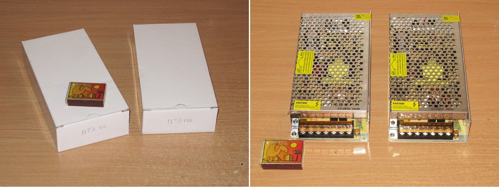
These power supplies usually come as an aluminum chassis with a metal cover, and this one follows the same classic design.
They’re the same size: 200 × 98 × 42 mm.
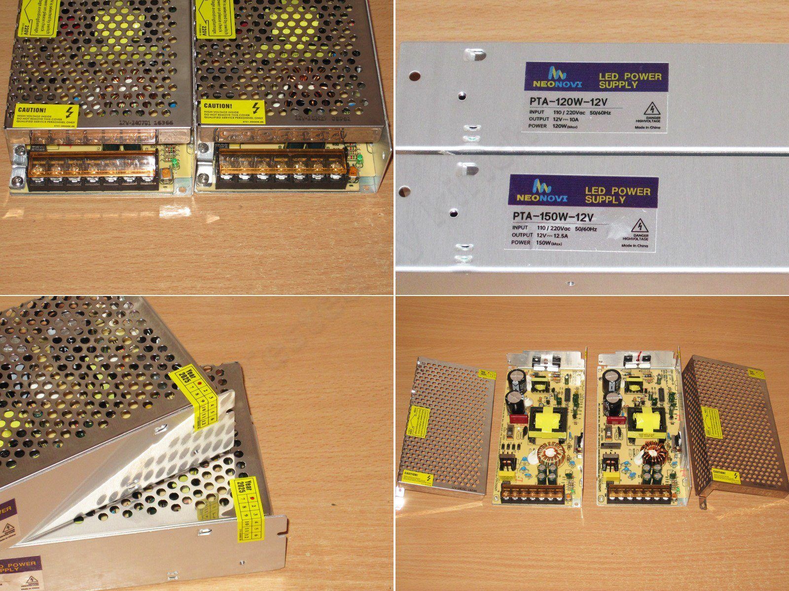
There’s a terminal block at one end, with paired outputs and a protective cover with a latch. Interestingly, Mean Well almost never puts covers on its terminal blocks. I don’t understand why; I think they’re convenient and improve safety.

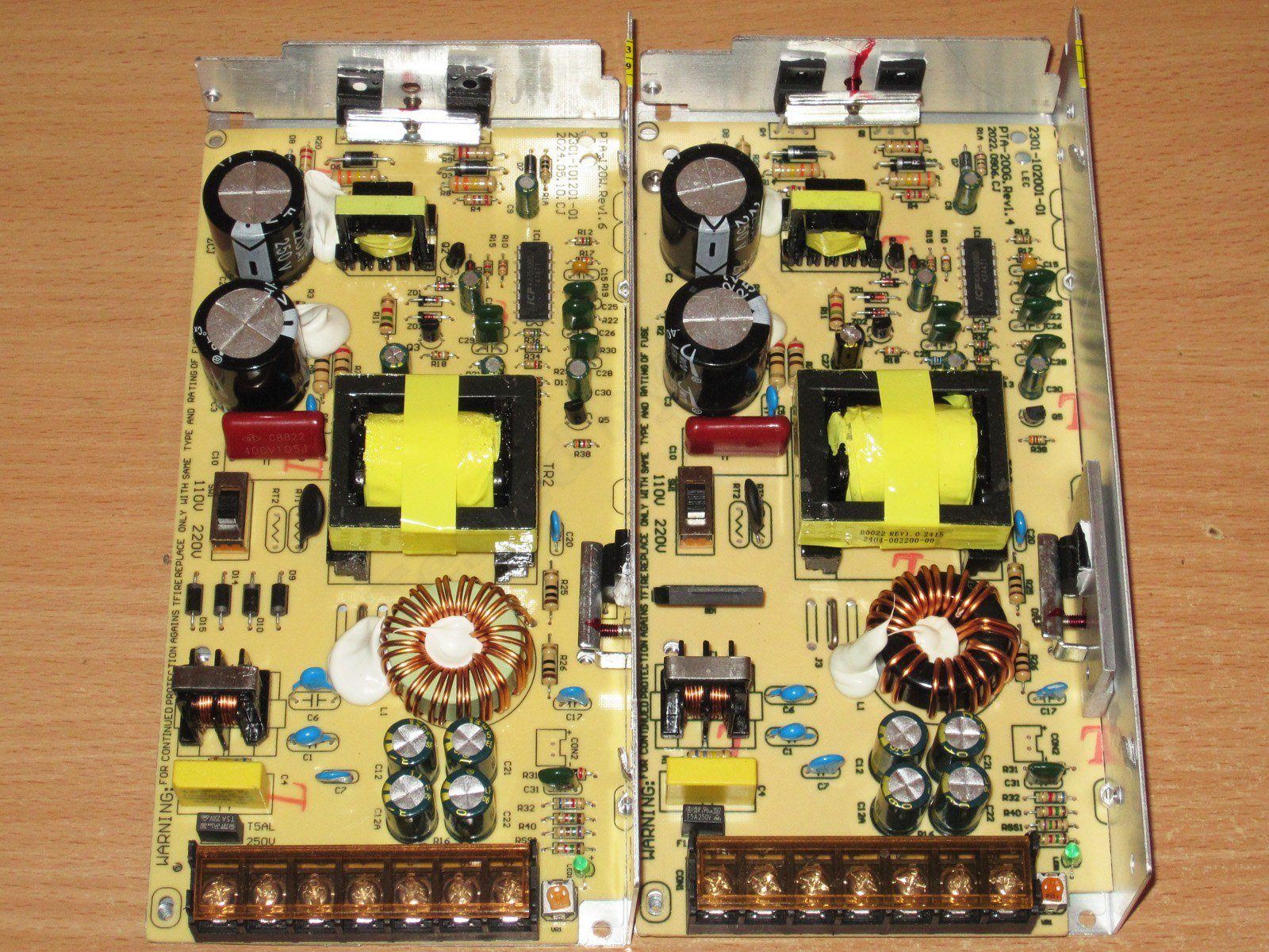
Inside, they look almost identical—you can’t tell them apart at a glance. That’s what I thought too, but no, there are some differences after all.

I’ll start with the PTA-120W-12V model, product link
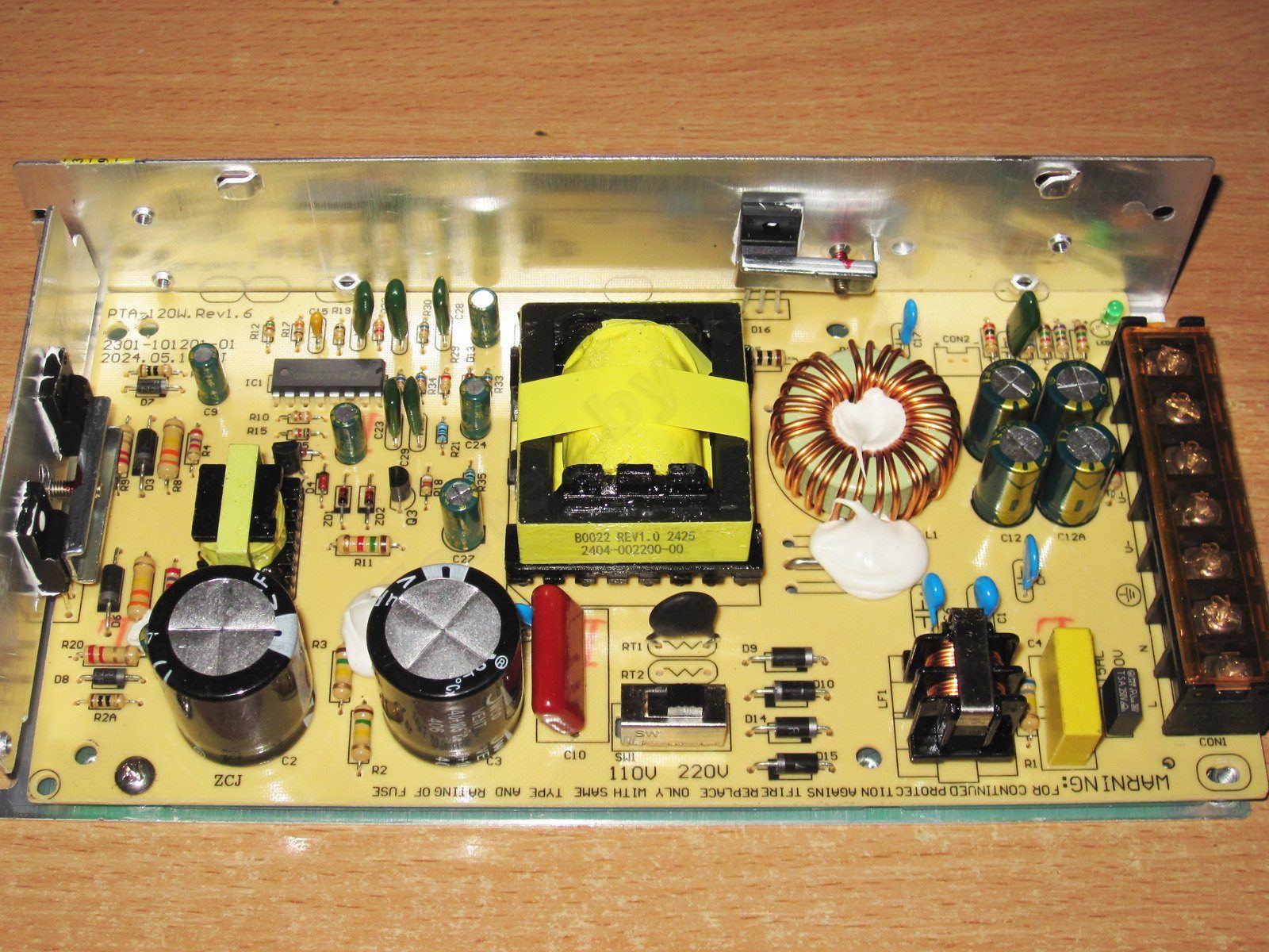
The layout is completely standard—nothing new here.

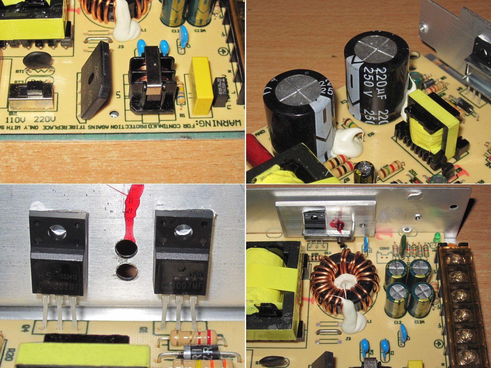
At the input, there’s a fuse, a filter, and a thermistor. There’s also, of course, a mains voltage selector.
A pair of capacitors rated at 220 µF.
The transistors are standard 13007s. They’re mounted with thermal paste, but they didn’t seem to sit very flush to me. Maybe that’s because the case is relatively soft, but we’ll check the temperature later.

At the output, there’s a 20 A, 100 V diode array, a power inductor, and four 1000 µF, 16 V capacitors. I’ll also note that Y capacitors are used where needed, rather than ordinary high-voltage capacitors.
This circuit design has an advantage: the output capacitors can be rated for a lower voltage than those in flyback power supplies, so 16 V is perfectly adequate here.
Also, since this uses a TL494 with two error amplifiers, power supplies like these can generally be used as battery chargers without any modifications. The reason is that the PWM controller fully regulates both the output current and voltage. If you connect a battery to the output, the power supply should enter CC mode. There is one caveat: you must check the output current and make sure it’s slightly higher than the rated value. If it’s much higher, the power supply will be overloaded.

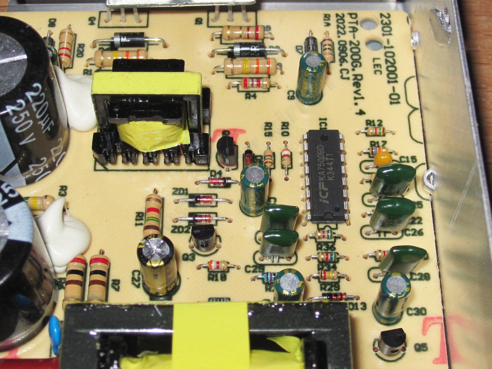
Even the control section layout is more or less standard; you can see the PWM controller and the pulse transformer.

The second power supply is the PTA-150W-12V, product link
It looks almost the same on the outside.

It also has a filter, the same capacitors, the same transistors, and the same output diode array. The inductor is slightly different.

Even the PWM controller section is the same.

But in fact, there are a few differences between these power supplies.
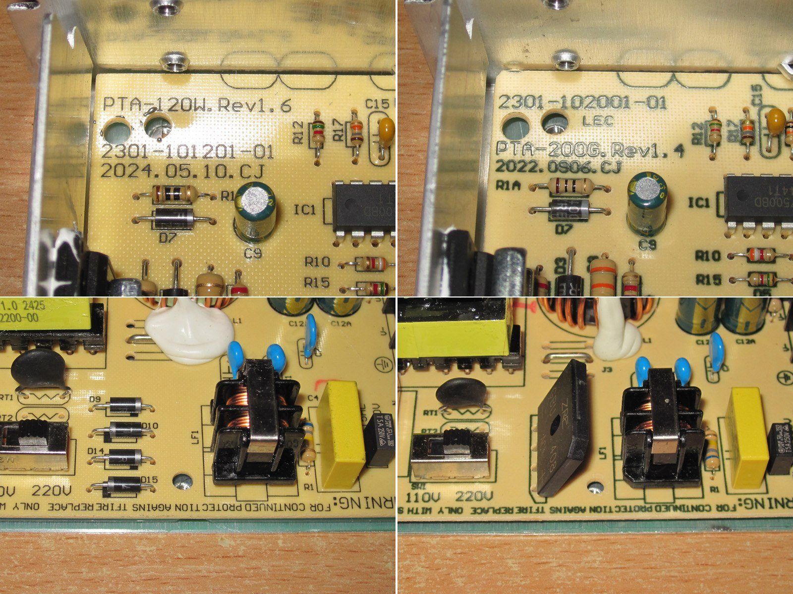
1. The board markings and revision are different, although I think they could easily have used a universal board.
2. The 120 W power supply uses discrete diodes for the input bridge, while the 150 W model has a single bridge rectifier. Again, I don’t see a major difference, although the bridge rectifier here is slightly more powerful.

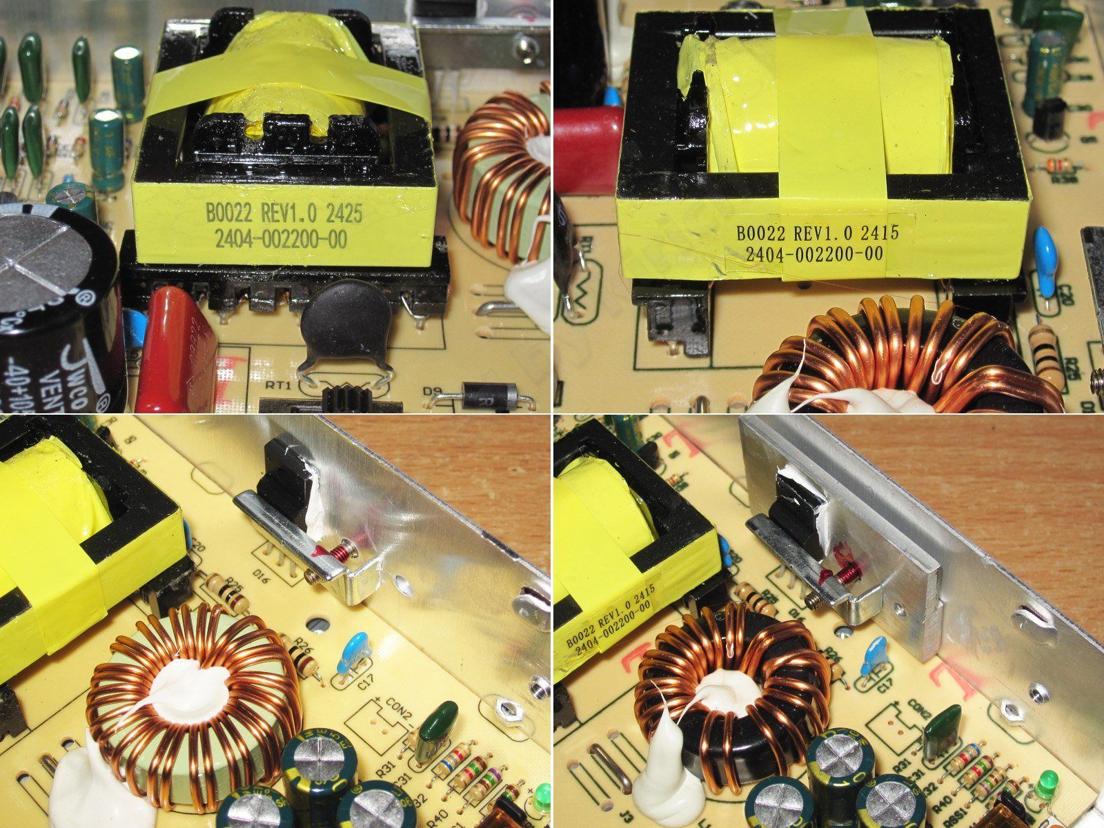
1. The transformers are the same size, but their markings differ by one digit. I think they’re actually identical.
2. The 120 W model's output diode assembly is attached directly to the case, while the 150 W model uses a heat spreader, which is certainly better.
The output inductors are also different: first, they have different cores, and second, they have different numbers of turns.

I took the board out of one of the power supplies. I could have checked them all, but I didn't see much point. There's an insulator between the board and the case.

The PCB is made of phenolic paper, as is the case with practically all of them. The layout is generally fine, although I did find one weak spot.

1. There's a relatively narrow clearance between the primary and secondary sides. I wouldn't say there's anything to worry about here, but I think they could have done better. This is actually the trace to the voltage selector, which we don't need at all in this case, so you can simply cut it on the left.
2. I also found signs of hand soldering. It looks like something went wrong after the board was assembled, and one of the PWM controller pins had to be soldered separately. This isn't anything unusual, really; it would have been worse if they hadn't soldered it.

Capacitors.
1, 2. The input capacitors have an actual capacitance of about 134 µF, compared with the stated 220 µF. That gives the filter a total capacitance of just 67 µF, versus the recommended 100–120 µF for the 120 W model and 130–150 µF for the 150 W model. Yes, both power supplies use the same capacitors, so the 150 W model's capacitance is about half the recommended value.
3. The output side is fine; I don't really have any complaints here.

As usual, I set up the test bench and move on to the tests.

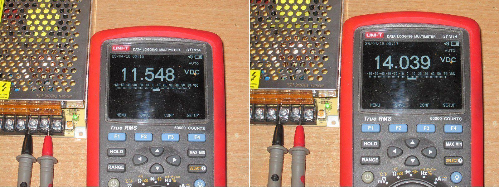
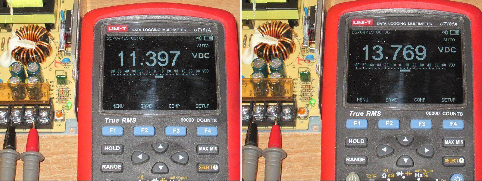
The power supplies have adjustable output voltage. The 120 W model can be adjusted from 11.55 to 14.04 V, which, incidentally, is quite suitable as a float voltage for lithium iron phosphate batteries.

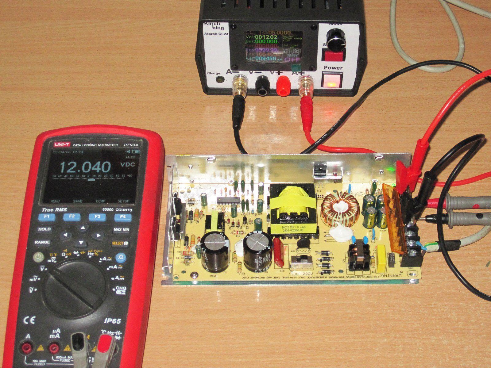
Voltage in different operating conditions.
Cold power supply, no load.

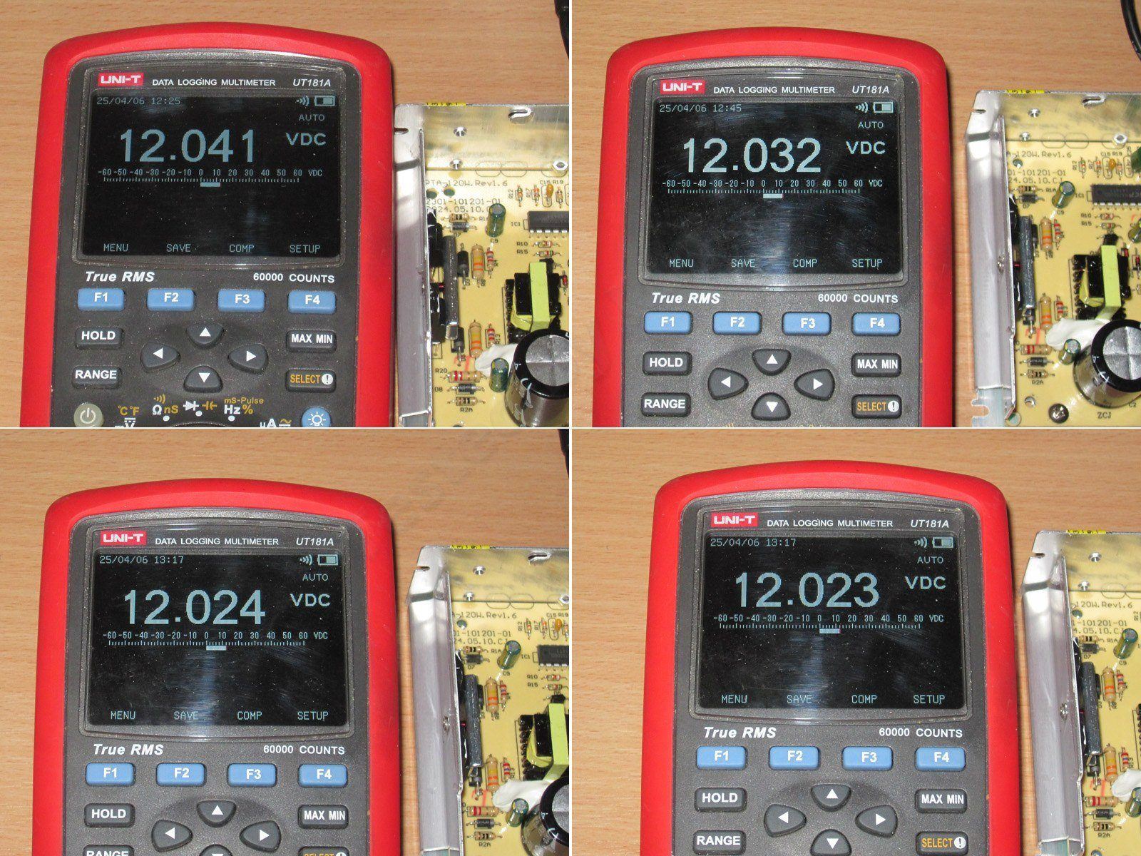
1. Cold power supply at 50% load
2. Warm power supply at 100% load
3. Hot power supply at 100% load
4. Hot power supply, no load.
Excellent results: the voltage varies slightly with temperature, but not with load. And considering that the requirements are less stringent for an adjustable power supply because it has a trim potentiometer, this is simply superb.

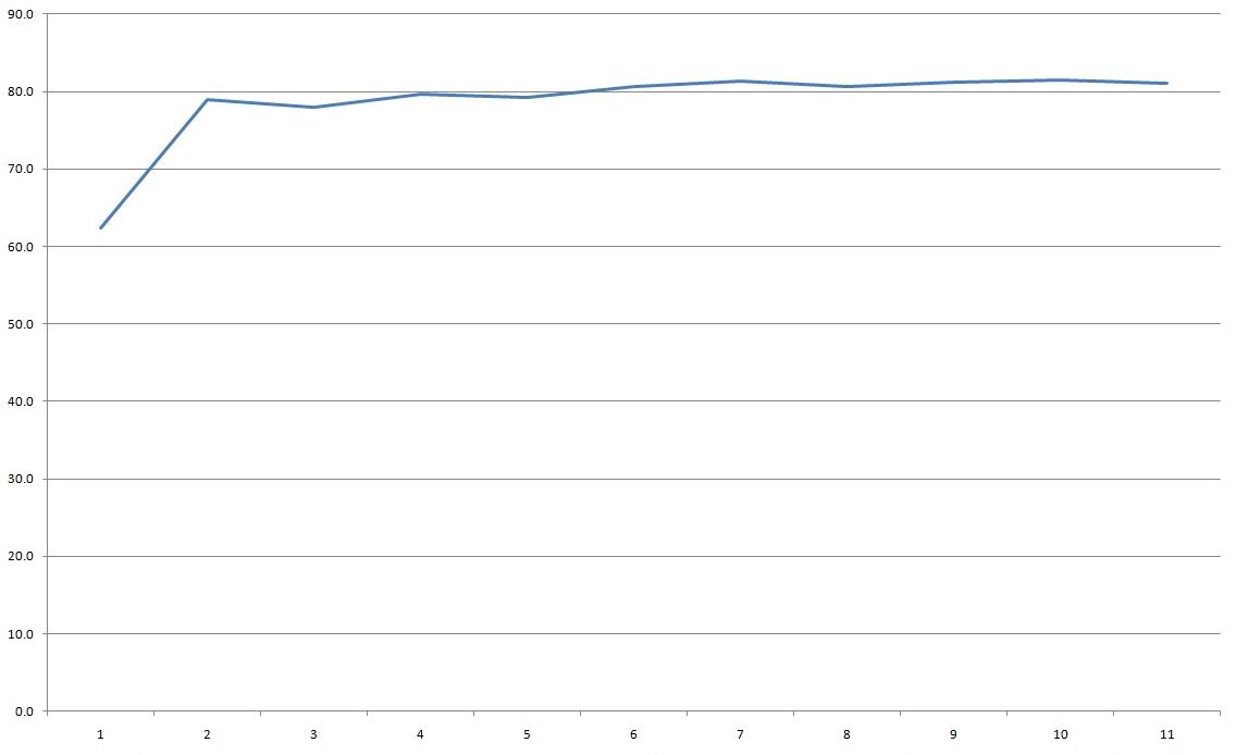
As expected, efficiency isn't very high, coming in at around 80–81% across almost the entire range.
Maximum current is around 11 A. At 12 A, the power supply switches to CC mode; I didn't measure the exact current at which it switches to CC mode.

The high-frequency ripple isn't very high—in fact, I'd even call it excellent. The first photo is with no load, at about 35 mV; the next ones are at 33%, 66%, and 100% load. Even at maximum load, the ripple is still around 35–40 mV peak-to-peak.

Low-frequency ripple at 100 Hz is predictably worse, due to the small input capacitor.

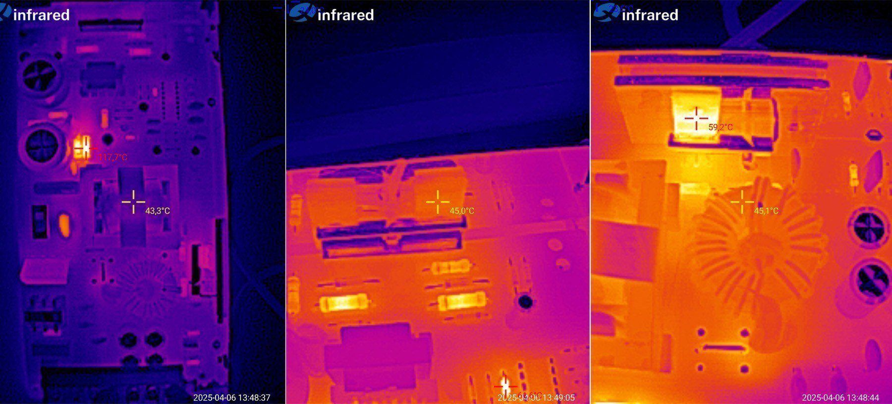
Temperature after warm-up at 50% load.
Everything looks great here; you could say the power supply runs cool. The hottest components were the resistors on the primary side, but that's normal.

Of course, the full-load test is more interesting. This looks fine to me as well.
Transistors — 63 °C
Transformer — 66 °C
Output diode assembly — 92 °C
Output inductor — 89 °C.
In my opinion, there's even a decent amount of power headroom here, which is certainly nice.

The second power supply, rated at 150 W.
Strangely enough, its voltage adjustment range is smaller, and I got a maximum of about 13.7 V, which is basically the float voltage for 12 V lithium iron phosphate batteries.

At the start of the test, the no-load voltage is 12.044 V.

1. At 50% load, the voltage on the cold power supply changed by just 1 mV
2. Warm power supply at 100% load
3. Hot power supply at 100% load
4. With the power supply hot and unloaded.
Here we see the same pattern as with the previous model: the voltage depends somewhat on temperature and is almost unaffected by the load current. Perfectly normal.

Efficiency across the 1–13 A load-current range. When raised to 14 A, the power supply switches to CC mode; I think the actual transition current is a little lower, but I didn't measure it separately.
Efficiency is slightly higher here, at around 83–84%.

The high-frequency ripple is a bit higher than on the 120 W version, but still within reasonable limits, measuring 60–70 mV at maximum power.
Results with no load and at 33%, 66%, and 100% load.

The low-frequency ripple results are more than predictable: 67 µF is simply too little for a 150 W power supply. When assessing ripple amplitude, always pay attention to the scale—how many mV per division. It's 20 mV here; the screenshot above was at 10 mV.

Temperatures after a run at 50% load—again, almost everything is cool.

And at 100% load.
Transformer: 75, excellent
Transistors: 68, superb
Diode assembly: 103, acceptable
Output inductor: 78, excellent.

The third power supply was delayed a little in transit. This is the PTA-200W-12V, product link
It looks exactly like the previous ones, even the dimensions are identical.

The inside is also almost identical, at least at a quick glance. Just to be safe: the 200 W one is on the right :)

1. The input section is the same as on the 150 W model.
2. The capacitors are also rated at 220 µF, but they're a different color.
3. The transistors, however, are beefier: 13009 here, not 13007.
4. The markings are different too.

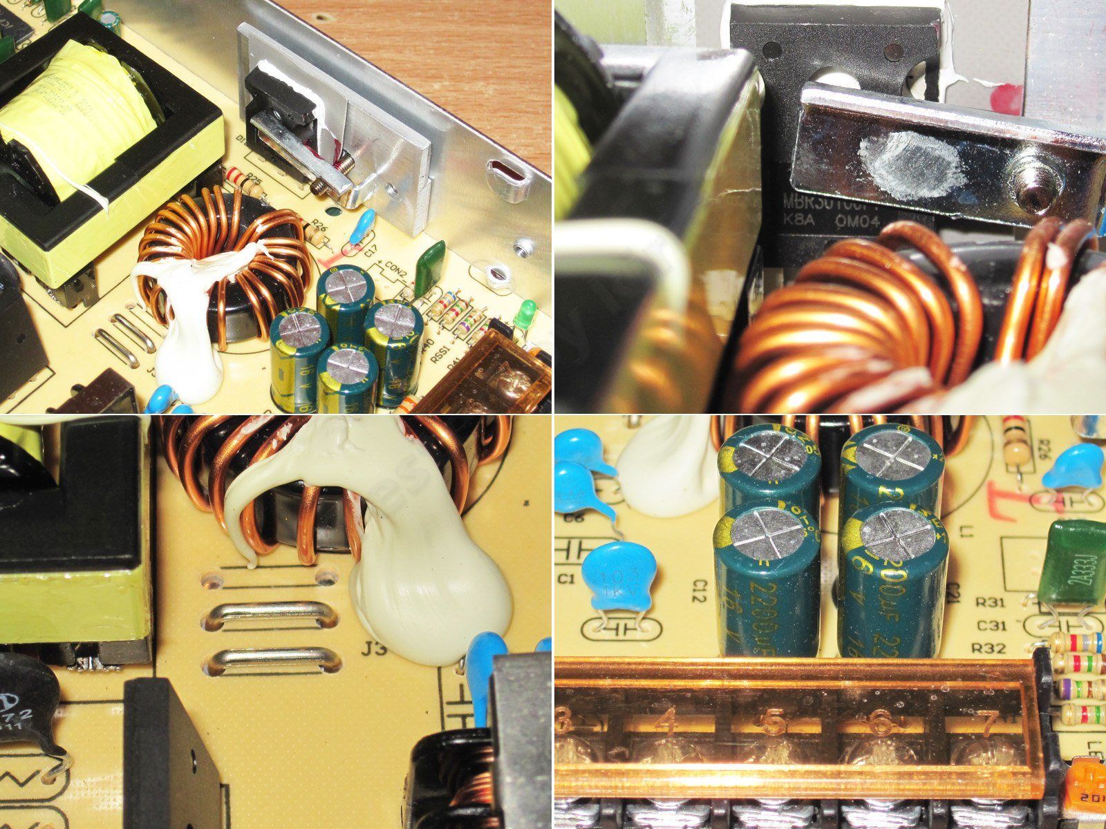
1. The power inductor is the same as on the 150 W model, but the transformer is clearly different. The 120 W and 150 W models had a 43×36×11 mm core, while the 200 W model has a 44×41×12 mm core.
2. The diode assembly is also larger now: 30 A, 100 V.
3. These are the shunts responsible for CC mode. There are two here, instead of one in the 120 W and 150 W units.
4. The output capacitors are also larger: 4×1000 µF before, now 4×2200 µF, which seems like more than enough to me.

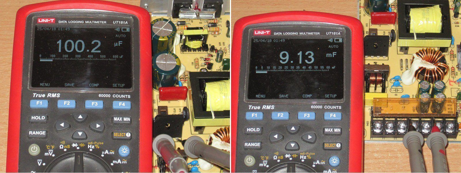
1. It turns out the input capacitors are also close to their rated capacitance. In series, they measure 100 µF, so each one is about 200 µF against a rated 220 µF. But I should say right away that 100 µF is too little for a 200 W power supply.
2. The output capacitors measure 9130 µF instead of the expected 11000 µF, but that's more than enough.

The voltage adjustment range is the same as on the 150 W version.

We set it to about 12 V; I got 12.03 V. By the way, although the adjustment range on these power supplies isn't very wide, I wouldn't call it precise.

1. Cold power supply at 8.5 A
2. Warm power supply at 17 A
3. Hot power supply at 17 A
4. Hot power supply with no load.
Everything is completely identical to the previous two models, with no issues here either.

Efficiency is about the same as the previous model, around 83–84%. Testing was carried out over the 1–18 A range; at 19 A, the unit switched to CC mode.

High-frequency ripple with no load and at 6, 12, and 18 A. No complaints here: even at 18 A (almost 110% load), the total ripple is around 50–60 mV.

But the ripple at 100 Hz is predictably high. Even the higher-capacitance capacitors don't help, although their capacitance is roughly proportionally higher, just like the power rating.

Temperature at 9 A, or about 108 W.
There's not much to comment on: everything is almost cool to the touch. Excellent.

Temperature at 18 A, or about 216 W.
Transformer: 85°C, fine.
Transistors: 72°C, excellent.
Output diode assembly: 115°C, a bit high. It might be worth clamping it down more firmly or applying better thermal paste.
Output inductor: 105°C, also a bit high.
I think at around 200 W the temperatures will drop a little, and that will basically be the long-term maximum for this power supply.

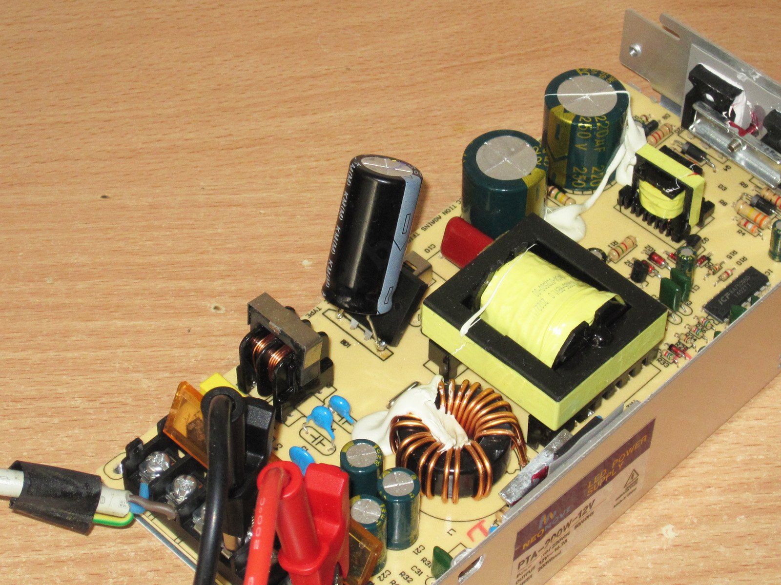
The 100 Hz ripple was really bothering me, so I decided to check how much it would drop if I brought the input capacitance up to the recommended value. So I added a 100 µF capacitor.
This gives us a 200 W power supply with about 200 µF of input capacitance. I soldered the capacitor directly to the diode bridge terminals. Yes, I've written before about increasing the filter capacitance by using one 400–450 V capacitor instead of two 200–250 V capacitors.

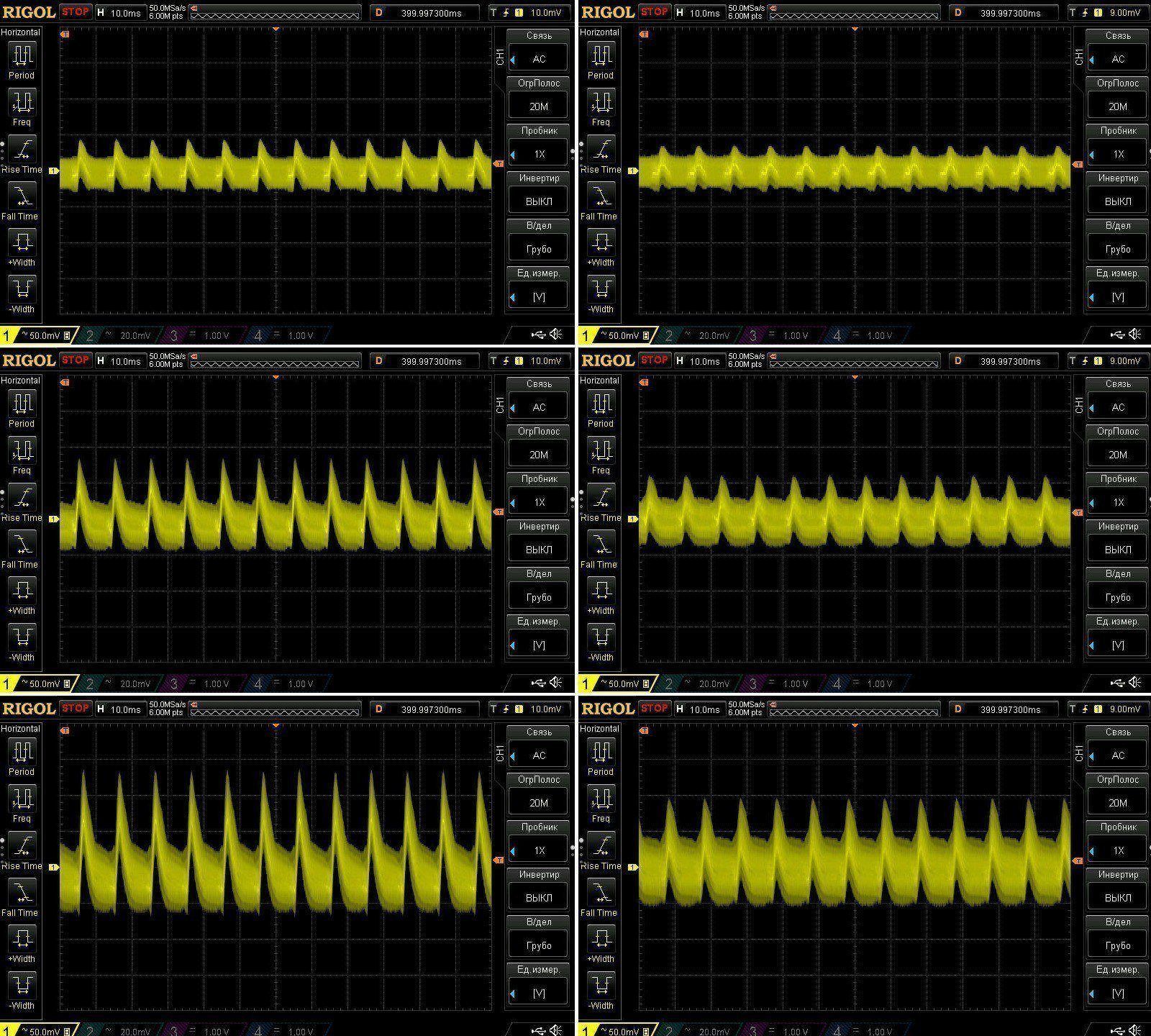
The ripple amplitude dropped significantly: original capacitors on the left, “by the book” capacitance on the right. Load currents are 6, 12, and 18 A.
In other words, the right capacitance won't give you zero ripple, or anything close to it, but it will bring it down to a certain level. Plus, as we can see, the ripple amplitude depends directly on the load power. Roughly speaking, with the added capacitor, the low-frequency ripple is about the same as with the original capacitors at 12 A.

Above, I mentioned that power supplies like these can be used as chargers. Naturally, I'm talking about versions based on the TL494 with current feedback.
For an experiment, I took a 150 W power supply and turned its voltage all the way up. It ended up very close to the buffer-mode voltage of a 4S LiFePO4 battery.

Next, I checked the current by simulating different battery voltages. In practice, with a battery and short wires, the results will be even better, because at higher voltages the current drops due to voltage loss in the wires. In other words, the current here is determined not by the load settings, but by the power supply itself, since the load is operating in CV mode.
A reminder: when testing a power supply operating in CV mode, the load should be in CC mode. When testing a charger in CC mode, the load should be in CV mode!
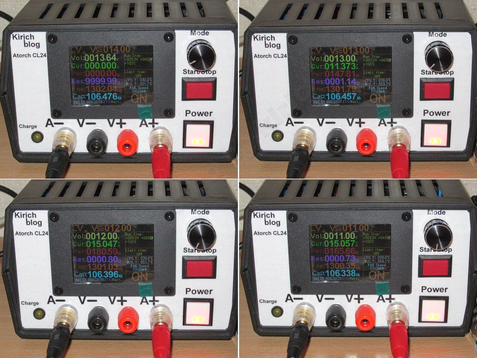
Anyway, that's not so important. Let's take a look.
At 14 V battery voltage, the current is zero, which makes sense: the power supply itself outputs less than that.
At 13 V, the current was about 11.4 A. With shorter, thicker wires, it would be higher.
As the voltage drops further, to 12 V and then 11 V, the voltage drop no longer matters, and the power supply fully regulates the current, which comes to about 15 A.
Of course, I'd prefer a slightly lower current, since toward the end of charging, the power in this setup is around 180 W, somewhat above the rated 150 W. There are a few ways to deal with this:
1. Don't worry about it and use it as is, since the power supply really can deliver that much power, and charging usually doesn't take all that long.
2. Adjust the value of the current-setting resistor.
3. File down the current-sense shunt a little to increase its resistance. It's best to file along its entire length. Roughly speaking, if you halve its cross-section, the current will also drop by half.
The first method is the easiest, the second is the proper way, and the third is a compromise that doesn't require knowing how to use a soldering iron :)

Conclusions.
Well, I think everything is pretty clear here. These are classic, standard designs, but budget ones, as we can see from the savings on the input capacitors. To be fair, though, the savings are really limited to those capacitors. The input filter is there, the transformer has plenty of headroom, and there's no overheating. The 120 W and 150 W units are practically cool, and I wouldn't say the build quality is bad either.
My only real complaint is the low-frequency ripple, so I wouldn't use these to power sensitive loads like amplifiers. And chargers, converters, lighting—no problem.
If you know your way around a soldering iron and can find a 68–100 µF, 400 V capacitor at home, you can easily get a better result.
In short, these are fairly decent budget power supplies for all sorts of undemanding jobs—workhorses of a sort.
That’s all for today. As always, I’d love to hear your comments. And thanks again to Vitaly for sending the samples. I’m off to test some other power supplies :)
A reminder: to keep up with new posts on the blog, I recommend following me on Instagram, where I’ll post notifications about all new articles and maybe write about something interesting now and then - link to the account
You can also subscribe to updates and new articles on the Telegram channel - https://t.me/KirichBlog
These power supplies are rightly considered classics. I don’t know how many similar models have been made, but I’m almost certain it’s well over several tens of millions. Of course, they differ from one another, but experience shows that the differences are mostly cosmetic and mainly concern the components installed in them.
Yes, these are power supplies based on the TL494, which has been around for several decades. They appeared at least as far back as the days of AT computers, but became widespread in the ATX era. Simpler versions with a single output voltage were also made alongside them; those are the models we’ll be looking at today.
There are three power supplies, but I’ll start with the two that arrived first. They’re rated at 120 and 150 W, which is about the lowest power rating you’ll usually find with this kind of circuit design. Below that, you generally get flyback converters, which are simpler and cheaper.
These power supplies usually come as an aluminum chassis with a metal cover, and this one follows the same classic design.
They’re the same size: 200 × 98 × 42 mm.
There’s a terminal block at one end, with paired outputs and a protective cover with a latch. Interestingly, Mean Well almost never puts covers on its terminal blocks. I don’t understand why; I think they’re convenient and improve safety.
Inside, they look almost identical—you can’t tell them apart at a glance. That’s what I thought too, but no, there are some differences after all.
I’ll start with the PTA-120W-12V model, product link
The layout is completely standard—nothing new here.
At the input, there’s a fuse, a filter, and a thermistor. There’s also, of course, a mains voltage selector.
A pair of capacitors rated at 220 µF.
The transistors are standard 13007s. They’re mounted with thermal paste, but they didn’t seem to sit very flush to me. Maybe that’s because the case is relatively soft, but we’ll check the temperature later.
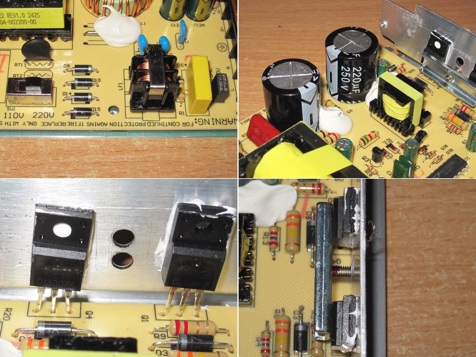
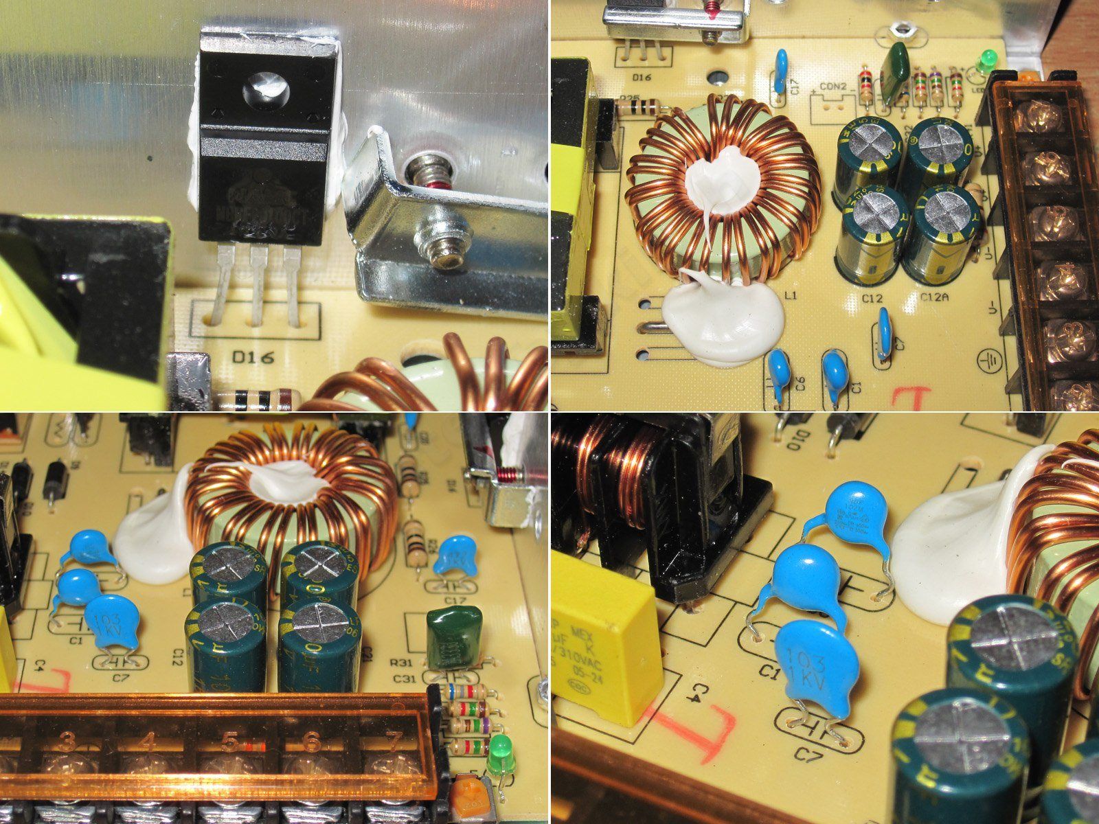
At the output, there’s a 20 A, 100 V diode array, a power inductor, and four 1000 µF, 16 V capacitors. I’ll also note that Y capacitors are used where needed, rather than ordinary high-voltage capacitors.
This circuit design has an advantage: the output capacitors can be rated for a lower voltage than those in flyback power supplies, so 16 V is perfectly adequate here.
Also, since this uses a TL494 with two error amplifiers, power supplies like these can generally be used as battery chargers without any modifications. The reason is that the PWM controller fully regulates both the output current and voltage. If you connect a battery to the output, the power supply should enter CC mode. There is one caveat: you must check the output current and make sure it’s slightly higher than the rated value. If it’s much higher, the power supply will be overloaded.
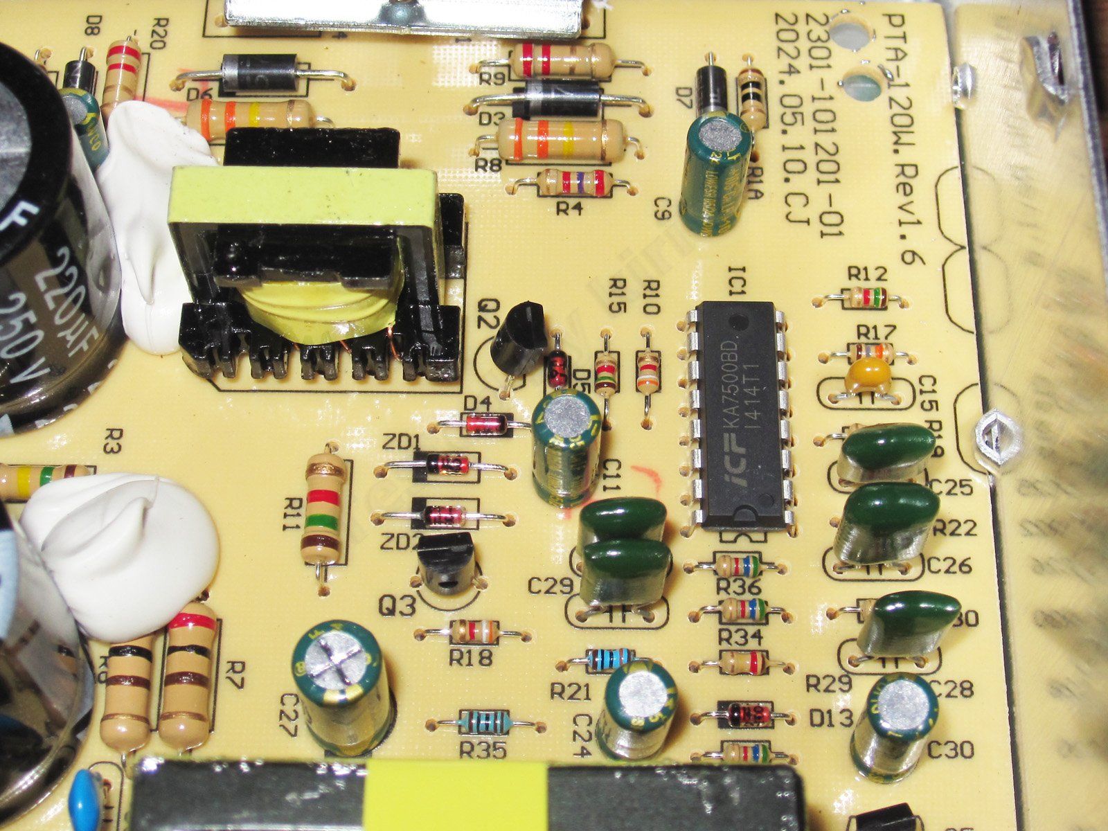
Even the control section layout is more or less standard; you can see the PWM controller and the pulse transformer.
The second power supply is the PTA-150W-12V, product link
It looks almost the same on the outside.
It also has a filter, the same capacitors, the same transistors, and the same output diode array. The inductor is slightly different.
Even the PWM controller section is the same.
But in fact, there are a few differences between these power supplies.
1. The board markings and revision are different, although I think they could easily have used a universal board.
2. The 120 W power supply uses discrete diodes for the input bridge, while the 150 W model has a single bridge rectifier. Again, I don’t see a major difference, although the bridge rectifier here is slightly more powerful.
1. The transformers are the same size, but their markings differ by one digit. I think they’re actually identical.
2. The 120 W model's output diode assembly is attached directly to the case, while the 150 W model uses a heat spreader, which is certainly better.
The output inductors are also different: first, they have different cores, and second, they have different numbers of turns.
I took the board out of one of the power supplies. I could have checked them all, but I didn't see much point. There's an insulator between the board and the case.

The PCB is made of phenolic paper, as is the case with practically all of them. The layout is generally fine, although I did find one weak spot.
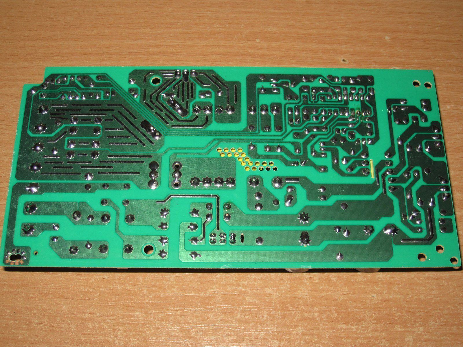
1. There's a relatively narrow clearance between the primary and secondary sides. I wouldn't say there's anything to worry about here, but I think they could have done better. This is actually the trace to the voltage selector, which we don't need at all in this case, so you can simply cut it on the left.
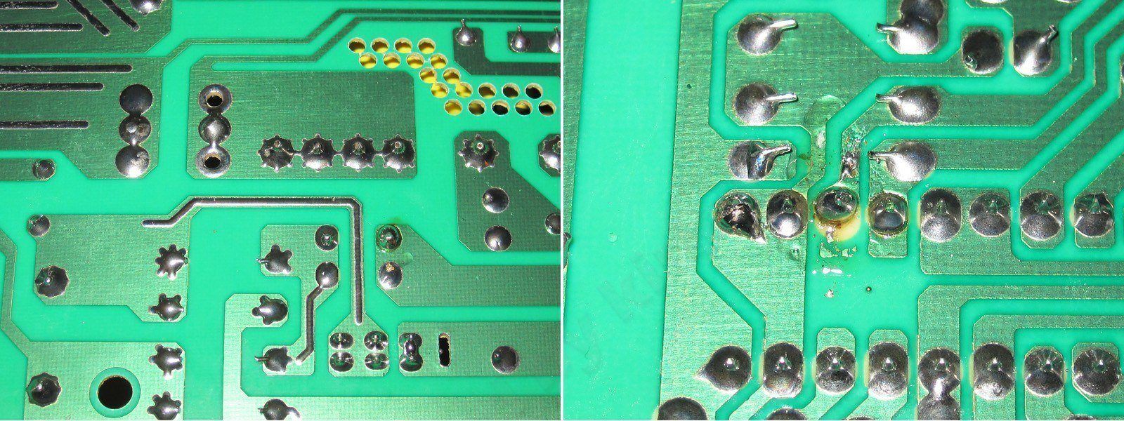
2. I also found signs of hand soldering. It looks like something went wrong after the board was assembled, and one of the PWM controller pins had to be soldered separately. This isn't anything unusual, really; it would have been worse if they hadn't soldered it.
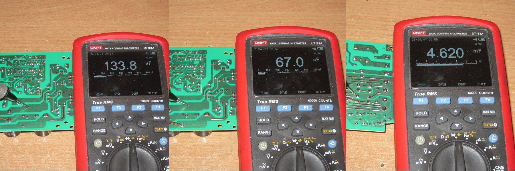
Capacitors.
1, 2. The input capacitors have an actual capacitance of about 134 µF, compared with the stated 220 µF. That gives the filter a total capacitance of just 67 µF, versus the recommended 100–120 µF for the 120 W model and 130–150 µF for the 150 W model. Yes, both power supplies use the same capacitors, so the 150 W model's capacitance is about half the recommended value.
3. The output side is fine; I don't really have any complaints here.
As usual, I set up the test bench and move on to the tests.
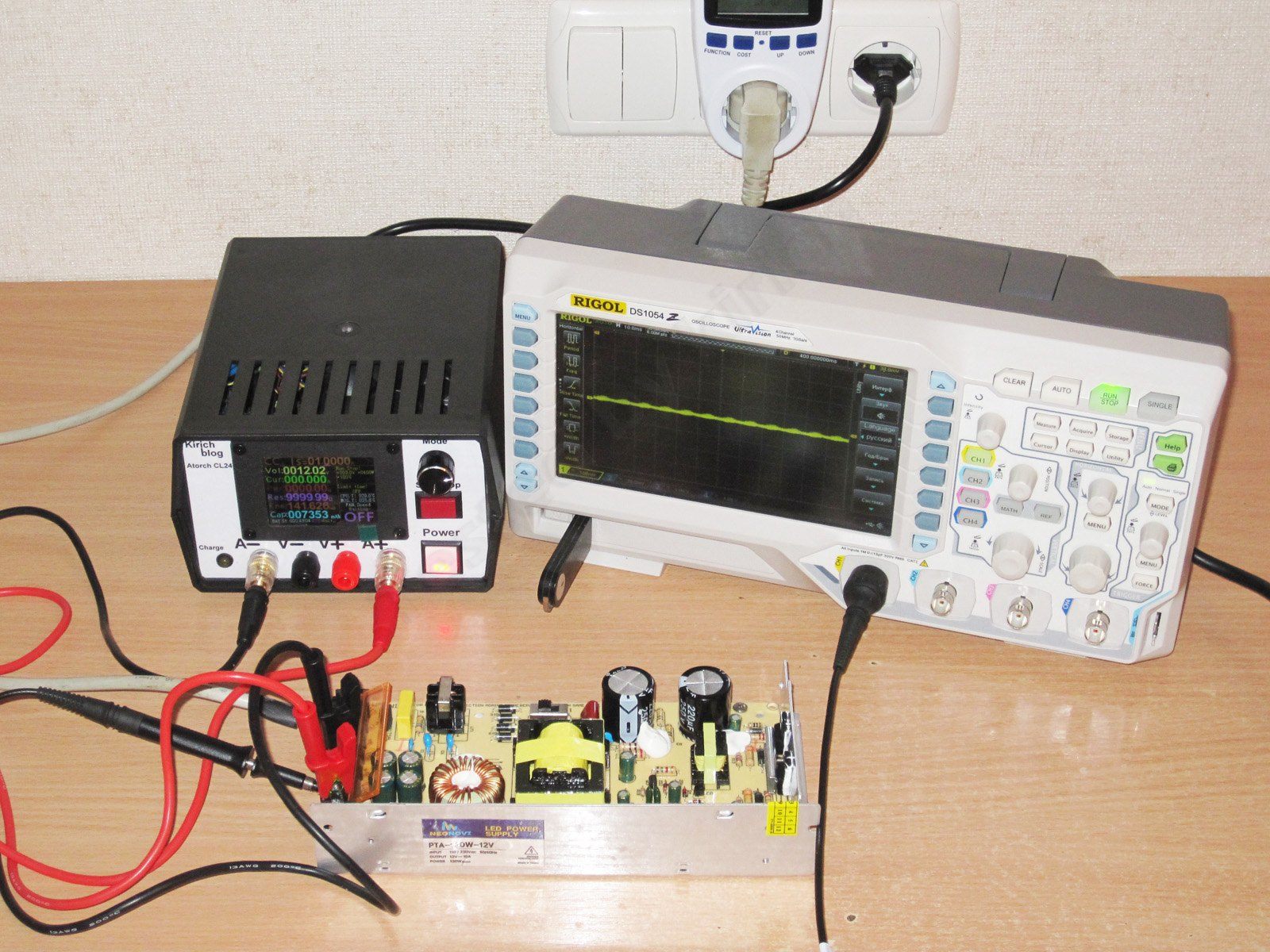
The power supplies have adjustable output voltage. The 120 W model can be adjusted from 11.55 to 14.04 V, which, incidentally, is quite suitable as a float voltage for lithium iron phosphate batteries.
Voltage in different operating conditions.
Cold power supply, no load.
1. Cold power supply at 50% load
2. Warm power supply at 100% load
3. Hot power supply at 100% load
4. Hot power supply, no load.
Excellent results: the voltage varies slightly with temperature, but not with load. And considering that the requirements are less stringent for an adjustable power supply because it has a trim potentiometer, this is simply superb.
As expected, efficiency isn't very high, coming in at around 80–81% across almost the entire range.
Maximum current is around 11 A. At 12 A, the power supply switches to CC mode; I didn't measure the exact current at which it switches to CC mode.
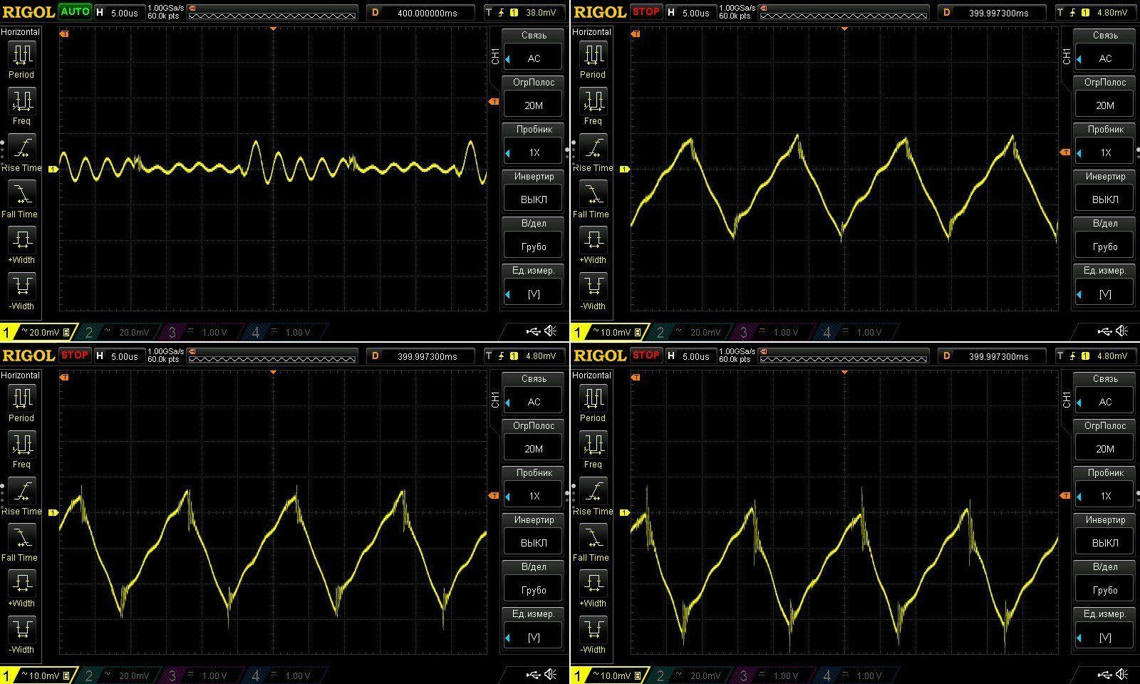
The high-frequency ripple isn't very high—in fact, I'd even call it excellent. The first photo is with no load, at about 35 mV; the next ones are at 33%, 66%, and 100% load. Even at maximum load, the ripple is still around 35–40 mV peak-to-peak.
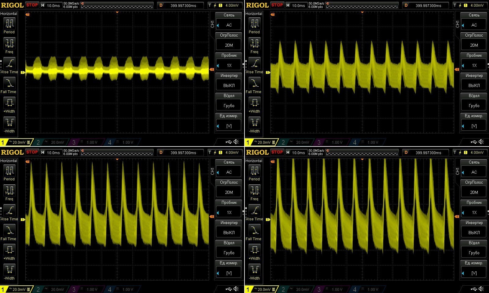
Low-frequency ripple at 100 Hz is predictably worse, due to the small input capacitor.
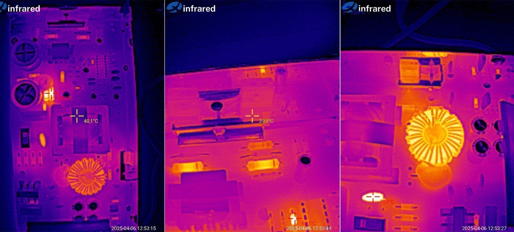
Temperature after warm-up at 50% load.
Everything looks great here; you could say the power supply runs cool. The hottest components were the resistors on the primary side, but that's normal.
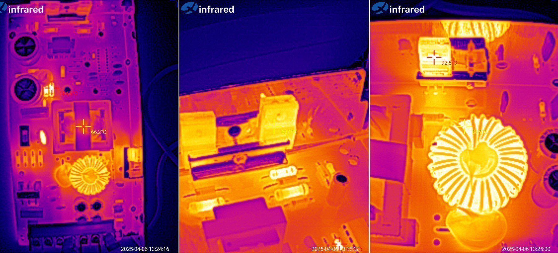
Of course, the full-load test is more interesting. This looks fine to me as well.
Transistors — 63 °C
Transformer — 66 °C
Output diode assembly — 92 °C
Output inductor — 89 °C.
In my opinion, there's even a decent amount of power headroom here, which is certainly nice.
The second power supply, rated at 150 W.
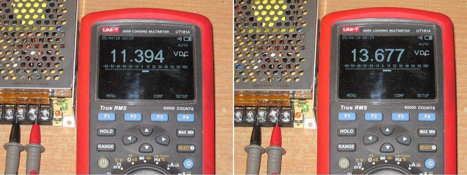
Strangely enough, its voltage adjustment range is smaller, and I got a maximum of about 13.7 V, which is basically the float voltage for 12 V lithium iron phosphate batteries.
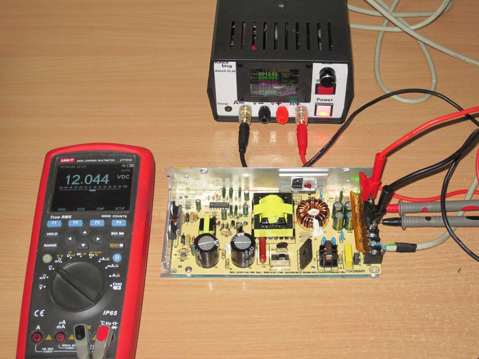
At the start of the test, the no-load voltage is 12.044 V.
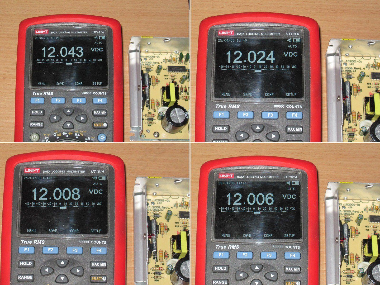
1. At 50% load, the voltage on the cold power supply changed by just 1 mV
2. Warm power supply at 100% load
3. Hot power supply at 100% load
4. With the power supply hot and unloaded.
Here we see the same pattern as with the previous model: the voltage depends somewhat on temperature and is almost unaffected by the load current. Perfectly normal.
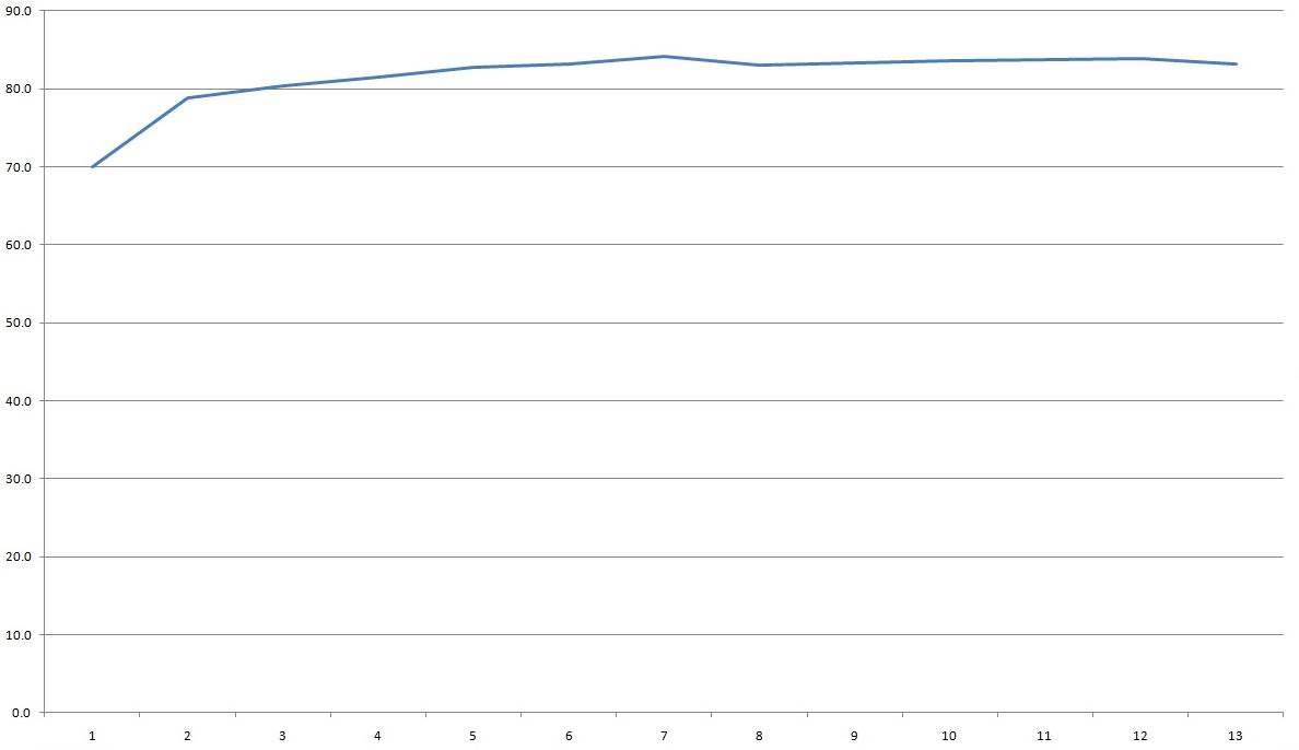
Efficiency across the 1–13 A load-current range. When raised to 14 A, the power supply switches to CC mode; I think the actual transition current is a little lower, but I didn't measure it separately.
Efficiency is slightly higher here, at around 83–84%.
The high-frequency ripple is a bit higher than on the 120 W version, but still within reasonable limits, measuring 60–70 mV at maximum power.
Results with no load and at 33%, 66%, and 100% load.
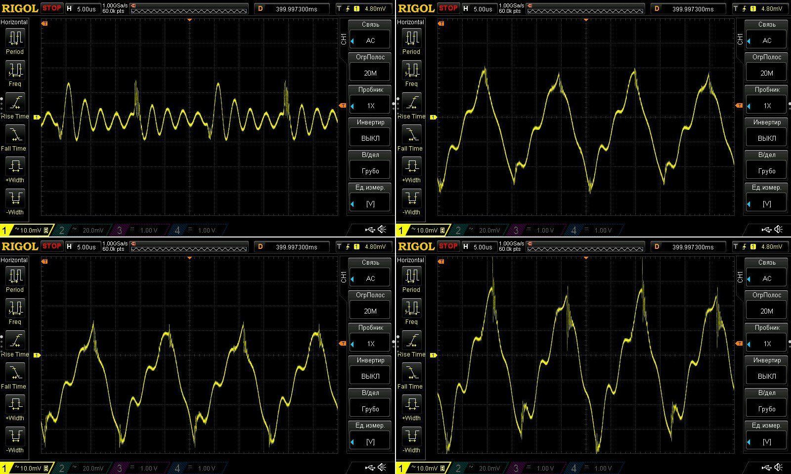
The low-frequency ripple results are more than predictable: 67 µF is simply too little for a 150 W power supply. When assessing ripple amplitude, always pay attention to the scale—how many mV per division. It's 20 mV here; the screenshot above was at 10 mV.

Temperatures after a run at 50% load—again, almost everything is cool.
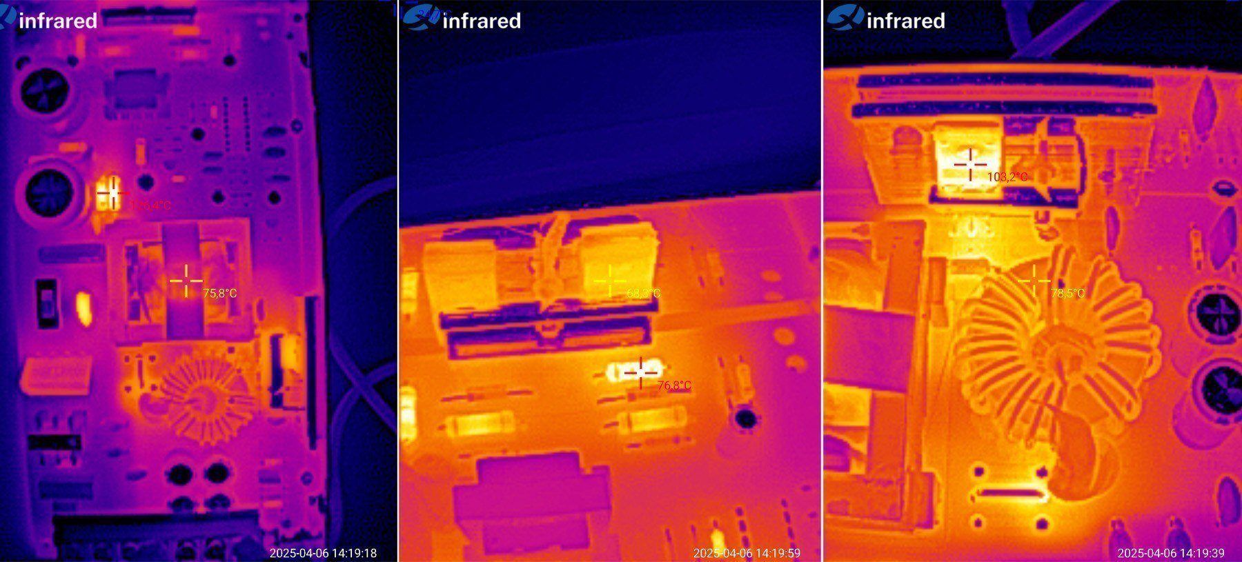
And at 100% load.
Transformer: 75, excellent
Transistors: 68, superb
Diode assembly: 103, acceptable
Output inductor: 78, excellent.
The third power supply was delayed a little in transit. This is the PTA-200W-12V, product link
It looks exactly like the previous ones, even the dimensions are identical.
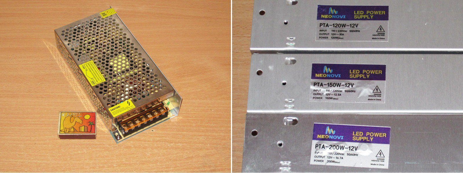
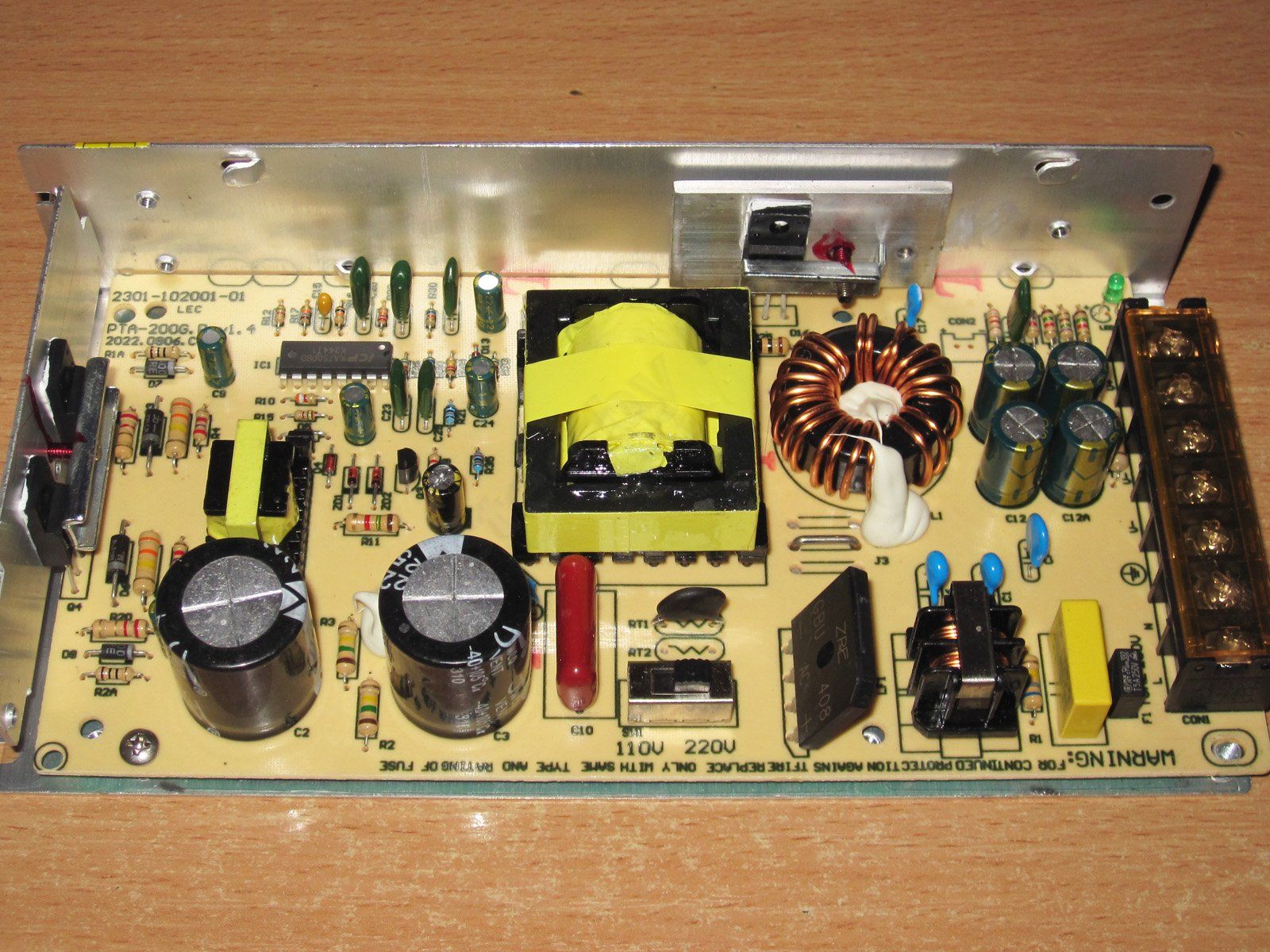
The inside is also almost identical, at least at a quick glance. Just to be safe: the 200 W one is on the right :)
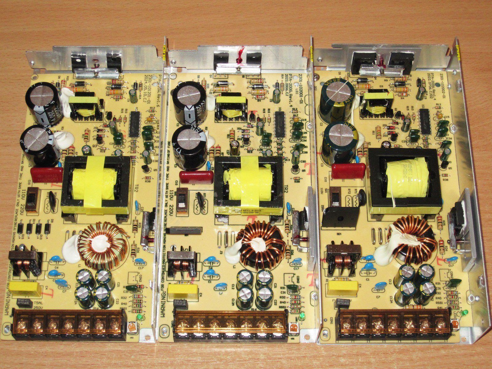
1. The input section is the same as on the 150 W model.
2. The capacitors are also rated at 220 µF, but they're a different color.
3. The transistors, however, are beefier: 13009 here, not 13007.
4. The markings are different too.
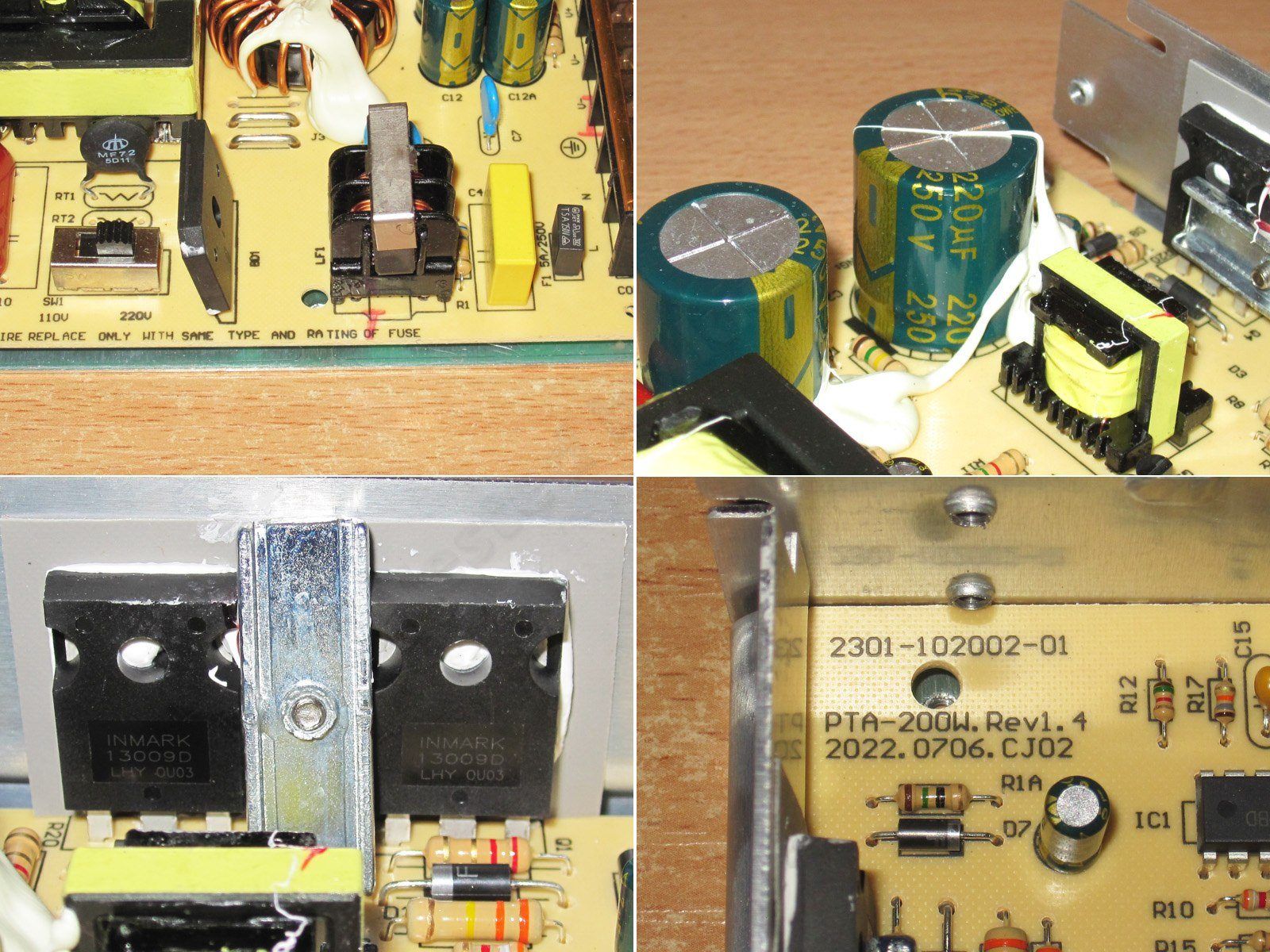
1. The power inductor is the same as on the 150 W model, but the transformer is clearly different. The 120 W and 150 W models had a 43×36×11 mm core, while the 200 W model has a 44×41×12 mm core.
2. The diode assembly is also larger now: 30 A, 100 V.
3. These are the shunts responsible for CC mode. There are two here, instead of one in the 120 W and 150 W units.
4. The output capacitors are also larger: 4×1000 µF before, now 4×2200 µF, which seems like more than enough to me.
1. It turns out the input capacitors are also close to their rated capacitance. In series, they measure 100 µF, so each one is about 200 µF against a rated 220 µF. But I should say right away that 100 µF is too little for a 200 W power supply.
2. The output capacitors measure 9130 µF instead of the expected 11000 µF, but that's more than enough.
The voltage adjustment range is the same as on the 150 W version.
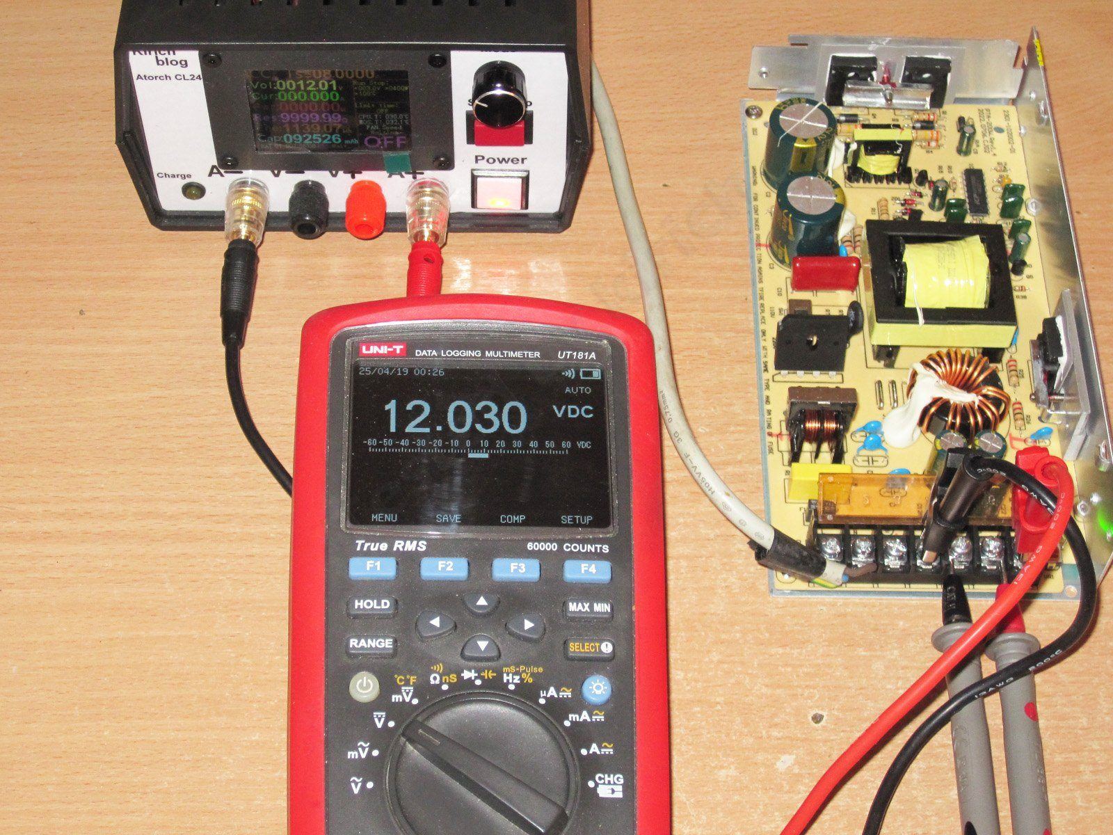
We set it to about 12 V; I got 12.03 V. By the way, although the adjustment range on these power supplies isn't very wide, I wouldn't call it precise.
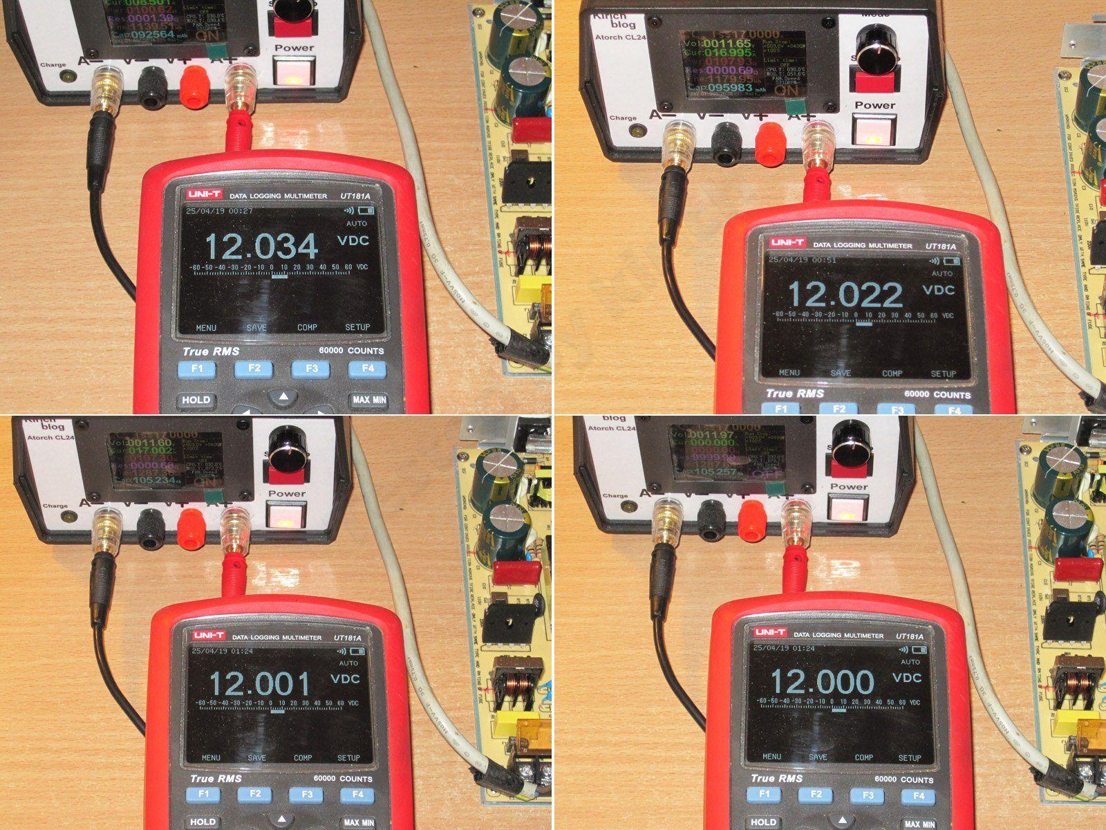
1. Cold power supply at 8.5 A
2. Warm power supply at 17 A
3. Hot power supply at 17 A
4. Hot power supply with no load.
Everything is completely identical to the previous two models, with no issues here either.
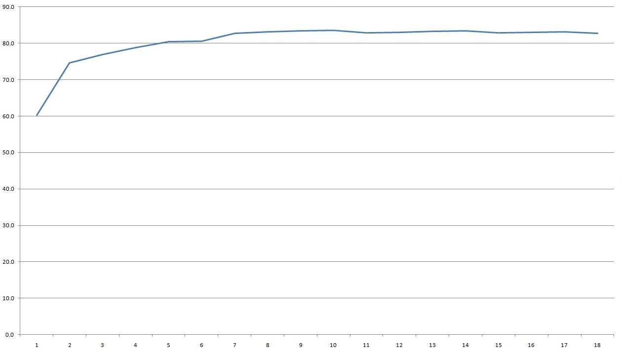
Efficiency is about the same as the previous model, around 83–84%. Testing was carried out over the 1–18 A range; at 19 A, the unit switched to CC mode.
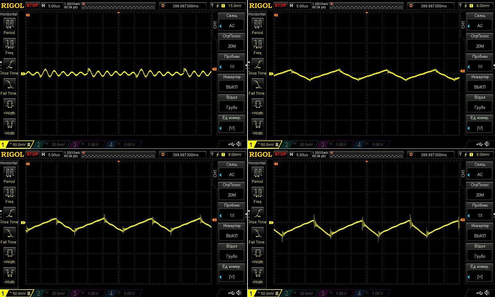
High-frequency ripple with no load and at 6, 12, and 18 A. No complaints here: even at 18 A (almost 110% load), the total ripple is around 50–60 mV.
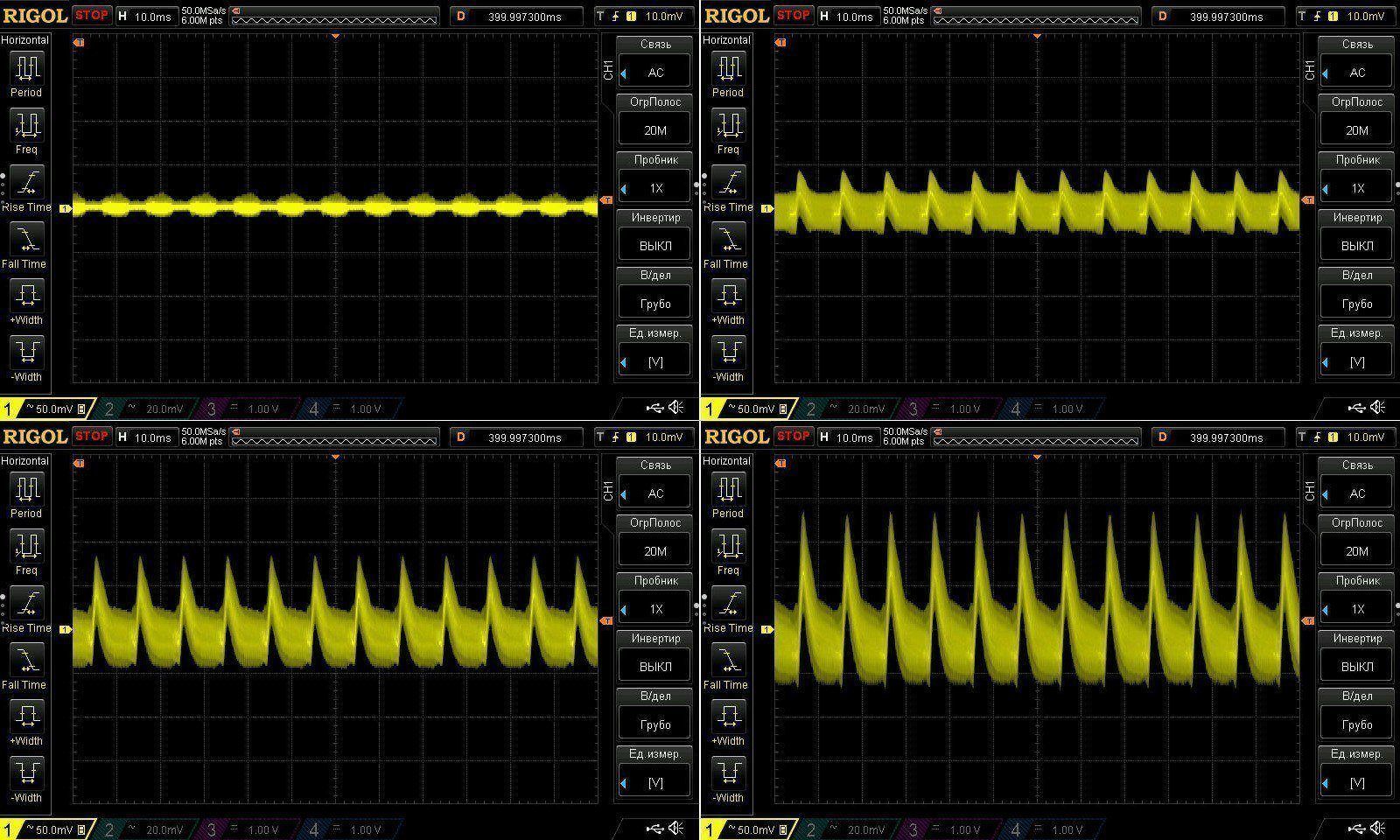
But the ripple at 100 Hz is predictably high. Even the higher-capacitance capacitors don't help, although their capacitance is roughly proportionally higher, just like the power rating.
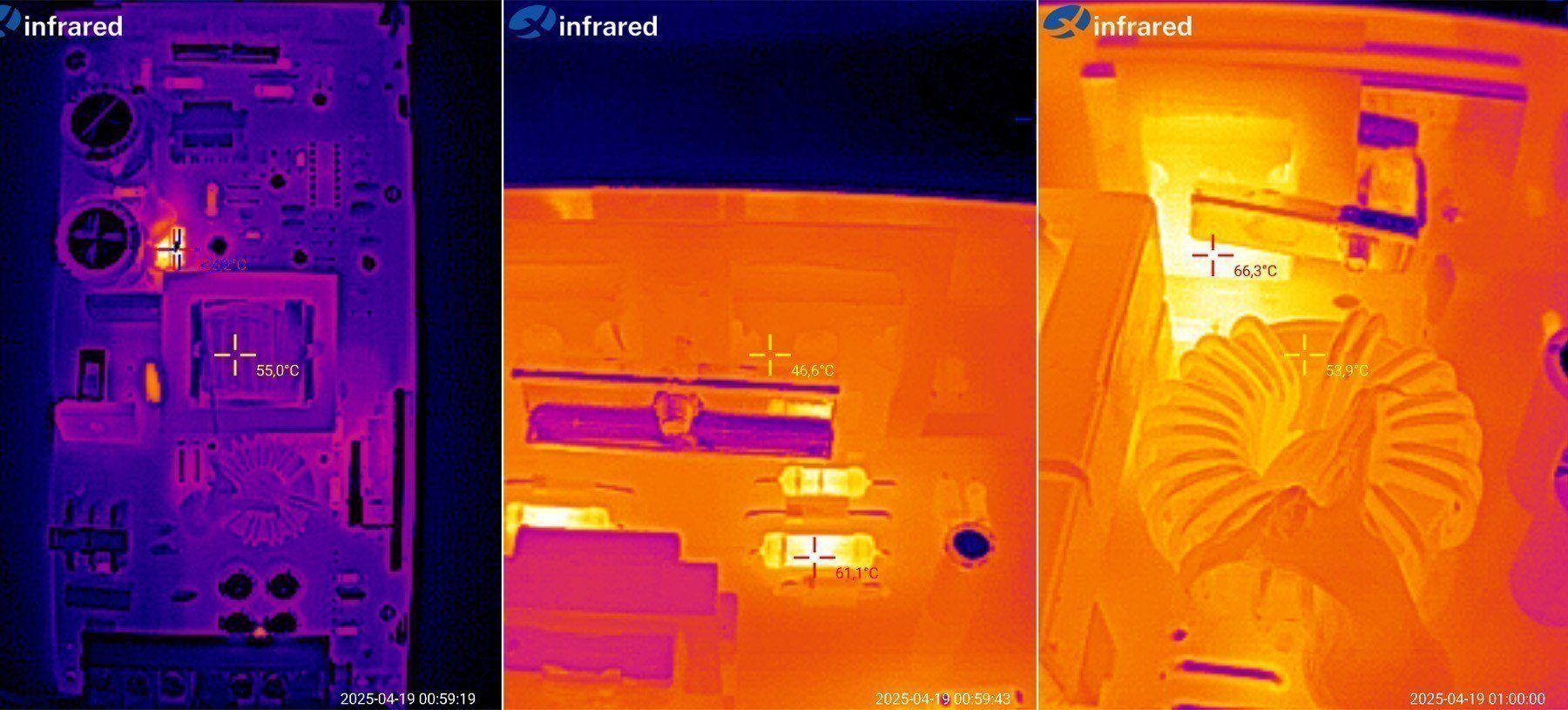
Temperature at 9 A, or about 108 W.
There's not much to comment on: everything is almost cool to the touch. Excellent.
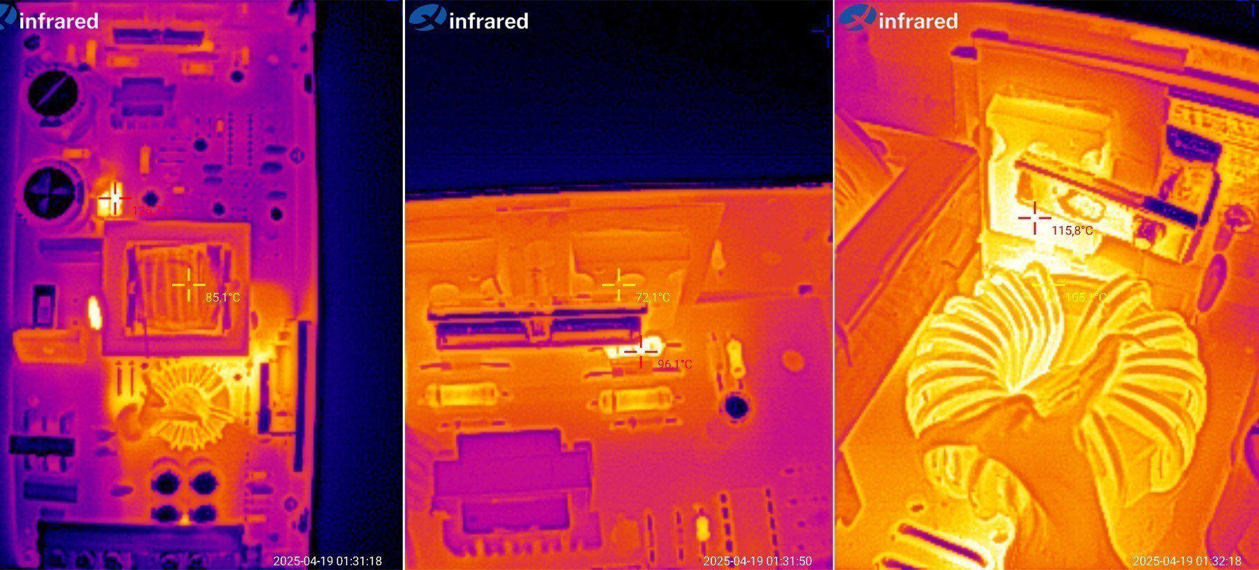
Temperature at 18 A, or about 216 W.
Transformer: 85°C, fine.
Transistors: 72°C, excellent.
Output diode assembly: 115°C, a bit high. It might be worth clamping it down more firmly or applying better thermal paste.
Output inductor: 105°C, also a bit high.
I think at around 200 W the temperatures will drop a little, and that will basically be the long-term maximum for this power supply.
The 100 Hz ripple was really bothering me, so I decided to check how much it would drop if I brought the input capacitance up to the recommended value. So I added a 100 µF capacitor.
This gives us a 200 W power supply with about 200 µF of input capacitance. I soldered the capacitor directly to the diode bridge terminals. Yes, I've written before about increasing the filter capacitance by using one 400–450 V capacitor instead of two 200–250 V capacitors.
The ripple amplitude dropped significantly: original capacitors on the left, “by the book” capacitance on the right. Load currents are 6, 12, and 18 A.
In other words, the right capacitance won't give you zero ripple, or anything close to it, but it will bring it down to a certain level. Plus, as we can see, the ripple amplitude depends directly on the load power. Roughly speaking, with the added capacitor, the low-frequency ripple is about the same as with the original capacitors at 12 A.
Above, I mentioned that power supplies like these can be used as chargers. Naturally, I'm talking about versions based on the TL494 with current feedback.
For an experiment, I took a 150 W power supply and turned its voltage all the way up. It ended up very close to the buffer-mode voltage of a 4S LiFePO4 battery.
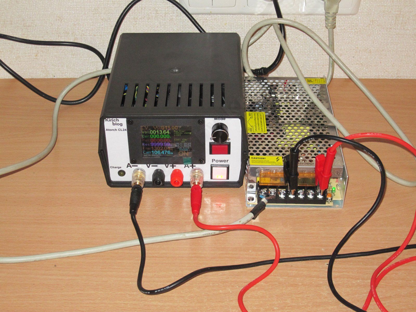
Next, I checked the current by simulating different battery voltages. In practice, with a battery and short wires, the results will be even better, because at higher voltages the current drops due to voltage loss in the wires. In other words, the current here is determined not by the load settings, but by the power supply itself, since the load is operating in CV mode.
A reminder: when testing a power supply operating in CV mode, the load should be in CC mode. When testing a charger in CC mode, the load should be in CV mode!
Anyway, that's not so important. Let's take a look.
At 14 V battery voltage, the current is zero, which makes sense: the power supply itself outputs less than that.
At 13 V, the current was about 11.4 A. With shorter, thicker wires, it would be higher.
As the voltage drops further, to 12 V and then 11 V, the voltage drop no longer matters, and the power supply fully regulates the current, which comes to about 15 A.
Of course, I'd prefer a slightly lower current, since toward the end of charging, the power in this setup is around 180 W, somewhat above the rated 150 W. There are a few ways to deal with this:
1. Don't worry about it and use it as is, since the power supply really can deliver that much power, and charging usually doesn't take all that long.
2. Adjust the value of the current-setting resistor.
3. File down the current-sense shunt a little to increase its resistance. It's best to file along its entire length. Roughly speaking, if you halve its cross-section, the current will also drop by half.
The first method is the easiest, the second is the proper way, and the third is a compromise that doesn't require knowing how to use a soldering iron :)
Conclusions.
Well, I think everything is pretty clear here. These are classic, standard designs, but budget ones, as we can see from the savings on the input capacitors. To be fair, though, the savings are really limited to those capacitors. The input filter is there, the transformer has plenty of headroom, and there's no overheating. The 120 W and 150 W units are practically cool, and I wouldn't say the build quality is bad either.
My only real complaint is the low-frequency ripple, so I wouldn't use these to power sensitive loads like amplifiers. And chargers, converters, lighting—no problem.
If you know your way around a soldering iron and can find a 68–100 µF, 400 V capacitor at home, you can easily get a better result.
In short, these are fairly decent budget power supplies for all sorts of undemanding jobs—workhorses of a sort.
That’s all for today. As always, I’d love to hear your comments. And thanks again to Vitaly for sending the samples. I’m off to test some other power supplies :)
This page was found when searching for:
силовой трансформатор 150 -200ватт выходное напряжение 2по 18 и 2 по 12
силовой трансформатор 150 -200ватт выходное напряжение 2по 18 и 2 по 12
This model is included in the summary table: Comparison of power supplies: ripple, efficiency, and temperature rise
The figures from this review are in the measurement database: Power supplies
Calculate manuallyAll calculators
Discounted products
You may be interested in



Discounted products
Support the project
All the content on the site and the advice are free, but we’d be grateful for your support of the project and the channel!
Comments8
Discuss on the forumHave a question or some experience to share? Discuss the article with the author and readers: the forum is a convenient place to share schematics and photos.
Go to the forumOnly registered readers can comment. It takes a minute to sign up, and you can log in with the same account you use on the forum.
Log inRegister
Comments are published in their original language.