
Two 12 V power supplies, 300 and 400 W, and both are interesting
593.90 ₴
A reminder: to keep up with new posts on the blog, I recommend following me on Instagram, where I’ll post notifications about every new article and maybe write about something interesting now and then: link to my account
You can also subscribe to updates and new articles on the Telegram channel - https://t.me/KirichBlog
So, here we have two models, both rated for 12 V, but one is 300 W and the other 400 W. I like the “new components” label on the box. The thing is, Chinese manufacturers really do sometimes use second-hand parts, most often salvaged capacitors. Usually, if you open up something inexpensive, you’ll find a bit of a “zoo,” even within a single batch. On the one hand, they often use branded components; on the other, their quality can of course vary.
You can also see the “full power” label, which means the supplies are designed to run at their full rated power. I usually recommend using power supplies at around 80%, leaving about 20% in reserve. This applies to almost all power supplies, but the point is that Chinese manufacturers often fudge the numbers: for example, they’ll print “500 W” in big letters, then add in tiny print somewhere in a far corner of the Chinese datasheet that it’s “no more than 20 seconds,” while the actual continuous rating is 50% of the stated figure. Unfortunately, they do this quite often.

The power supplies are branded and have all the necessary markings. By the way, I was thinking: what if I put a small label somewhere on the units that pass my tests and that I can recommend, something like “Tested by kirich”? For people who know me, that could serve as a kind of quality rating, since there really are models I like. If I found issues with a model and they were later fixed, I’d add the label only after the fixes and a successful retest. Anyway, just thinking out loud.
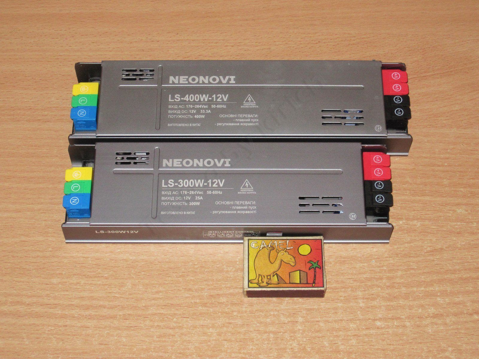
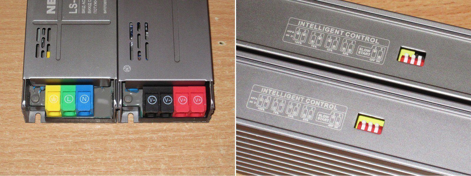
1. The connections use spring terminals. That’s neither good nor bad: screw and spring terminals each have their pros and cons. Just bear in mind that the terminals used in power supplies are often rated for 16 A, and less often for 20–25 A. If you have several terminals in parallel and are connecting a single wire to two of them, I recommend splitting the wire into a Y shape and connecting it to all the terminals. This reduces the load on each terminal.
The green terminal for the live wire looks a little odd; apparently they didn’t have a brown one.
2. There’s a three-position switch on the side that lets you change the output voltage. The idea is that this power supply is intended for lighting systems (though there’s nothing stopping you from using it for other purposes). The switch lets you set the strip brightness to 25, 50, 75, or 100%, and also ramp it up smoothly to the selected level.
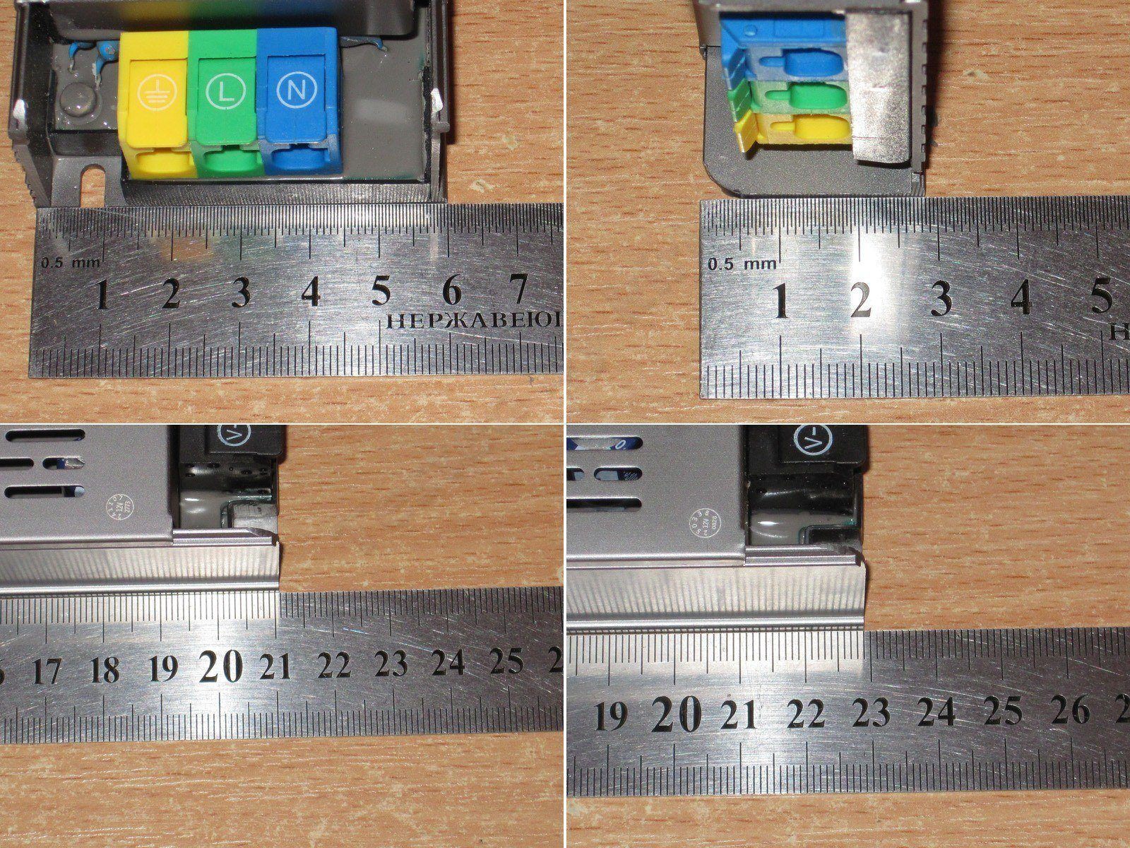
It’s 60 mm wide and about 28 mm high; both dimensions are the same for the two units. Their lengths differ: 210 and 230 mm.
Let’s start with the LS-300W-12V model: 12 V, 300 W, 25 A, respectively - link
It’s immediately clear that this supply is interesting, at least because of its LLC topology, which has several advantages over the typical “half-bridge” topology also used in power supplies of comparable power.
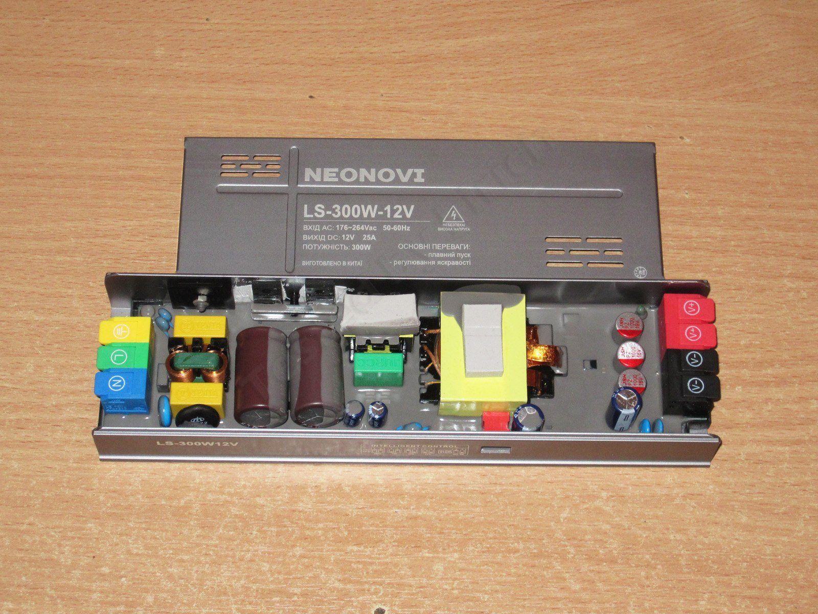
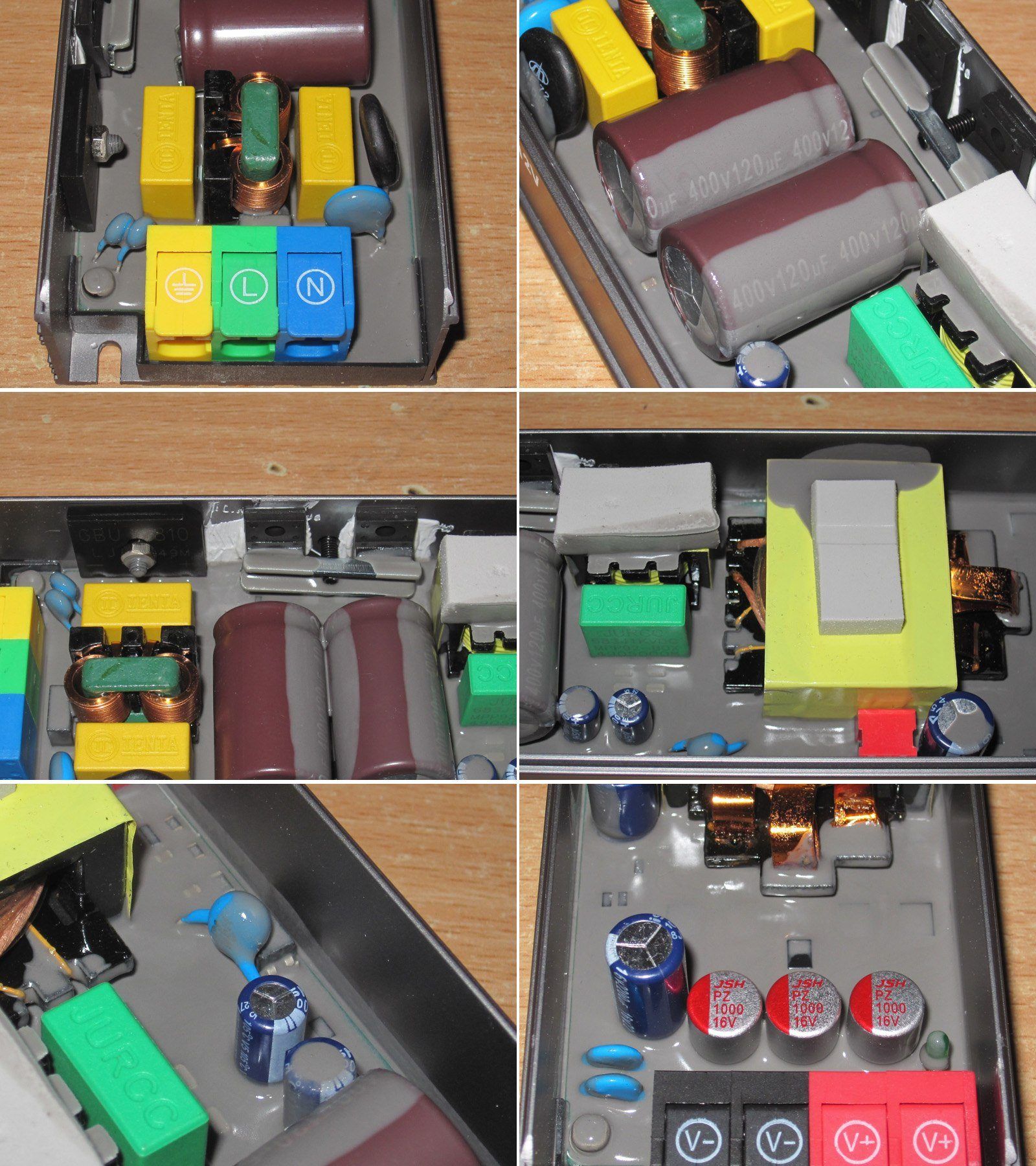
1. There’s a proper input filter, with not just a thermistor but also a varistor rated for 470 V peak.
2. There are two 120 µF input capacitors. The manufacturer’s name is hard to make out; I think it’s Aishi, which is already a good sign.
3. The transistors and bridge rectifier are screwed to the case, which acts as a heatsink. The transistors are mounted with thermal paste; the bridge seems to be mounted without it. The case is profiled, so it’s fairly rigid.
4. The LLC converter’s resonant tank: an inductor (choke) + an inductor (transformer) and a capacitor (below the choke).
5. They didn’t forget the Y capacitor, either.
6. The output has three 1000 µF polymer capacitors and one regular 2200 µF capacitor, all rated for 16 V.
The circuit board is coated with a soft, sealant-like compound. Keep in mind that this power supply isn’t waterproof; it’s merely moisture-resistant, for example against condensation. The coating also improves electrical safety in case dust gets inside.
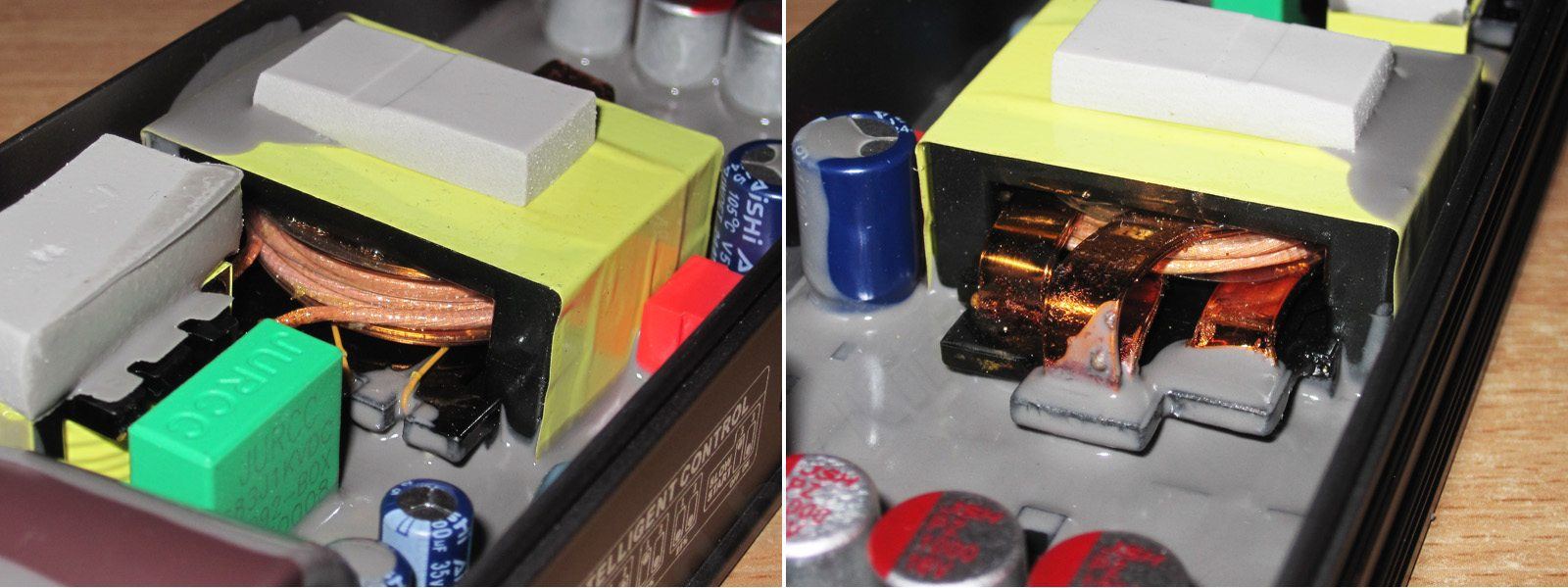
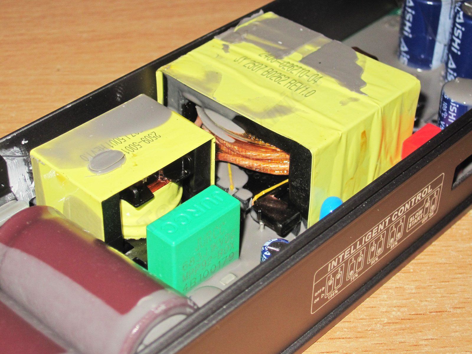
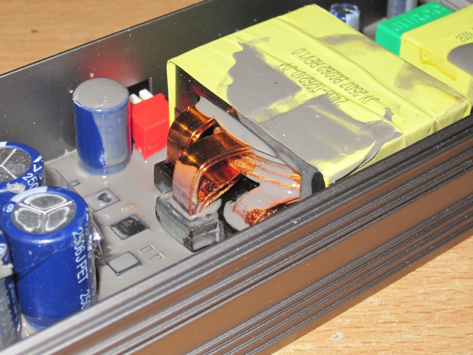
The transformer looks nice. The primary winding appears to be litz wire, while the secondary is made from a copper busbar. This design helps reduce the skin effect.
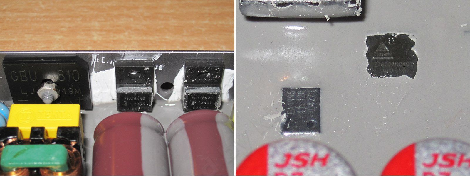
I only got to the transistors after the tests, so as not to compromise the validity of the testing.
On the input side, the PTA18N45 is rated at 18 A, 450 V, judging by the markings.
On the output side, there are four ZTG020N04 MOSFETs, controlled by the synchronous rectifier controller TEA1995.
I have to say, this is a beautiful design: an LLC converter, synchronous rectification, and polymer capacitors. I like it already.
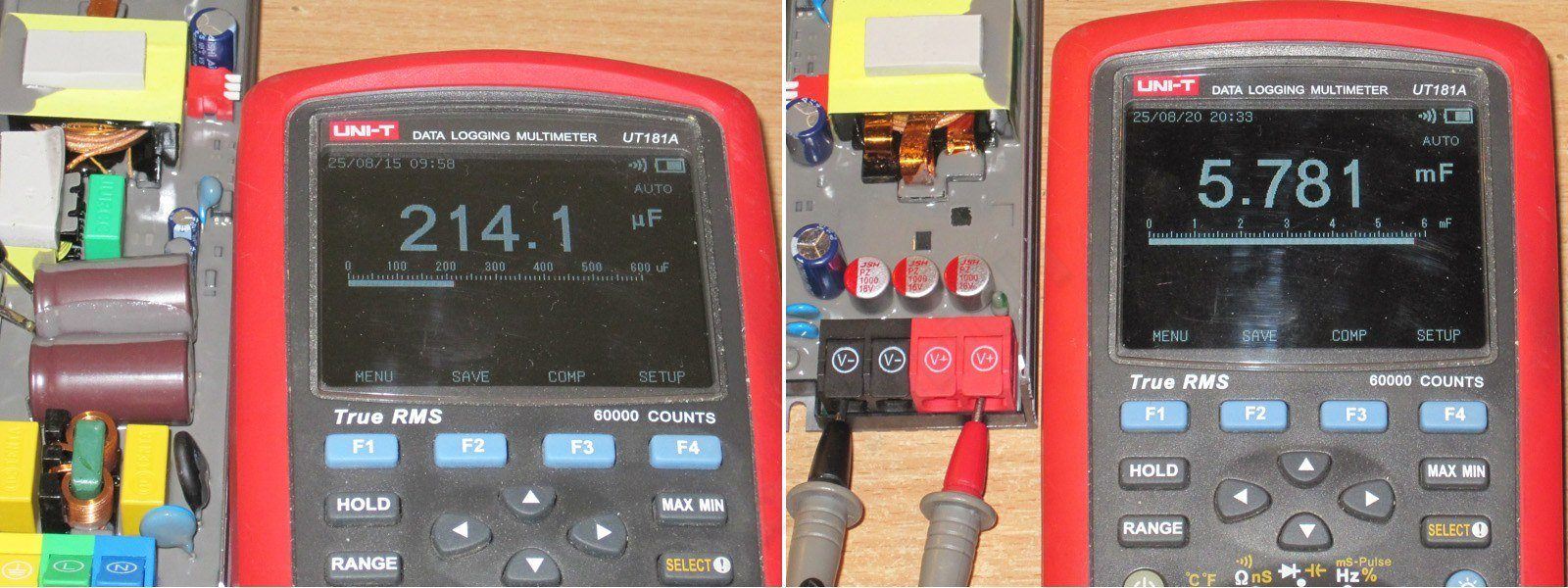
The measured input capacitance was 214/2 = 107 µF, compared with the rated 120 µF—well within the tolerance of both the capacitors and the measurement. The output capacitors measured 5780 µF, which is also fine.
As a reminder, the output capacitance depends heavily on the power supply topology and its operating frequency.
The dimming method really surprised me. PWM dimming is often used because it’s simple, provides a guaranteed equivalent power level (roughly speaking, a 35% duty cycle corresponds to 35% brightness for LED strips), and doesn’t shift the color temperature.
But PWM dimming also has several drawbacks. First, it puts extra load on the power supply. Second, it’s essentially a noise generator. Third, there’s ripple.
This unit instead controls the voltage: each power setting corresponds to a different output voltage. It’s a less precise approach, but in practice there’s virtually no ripple or interference.
The first two switches select the voltage at which the LED strips will deliver about 25%, 50%, 75%, or 100% of their power.
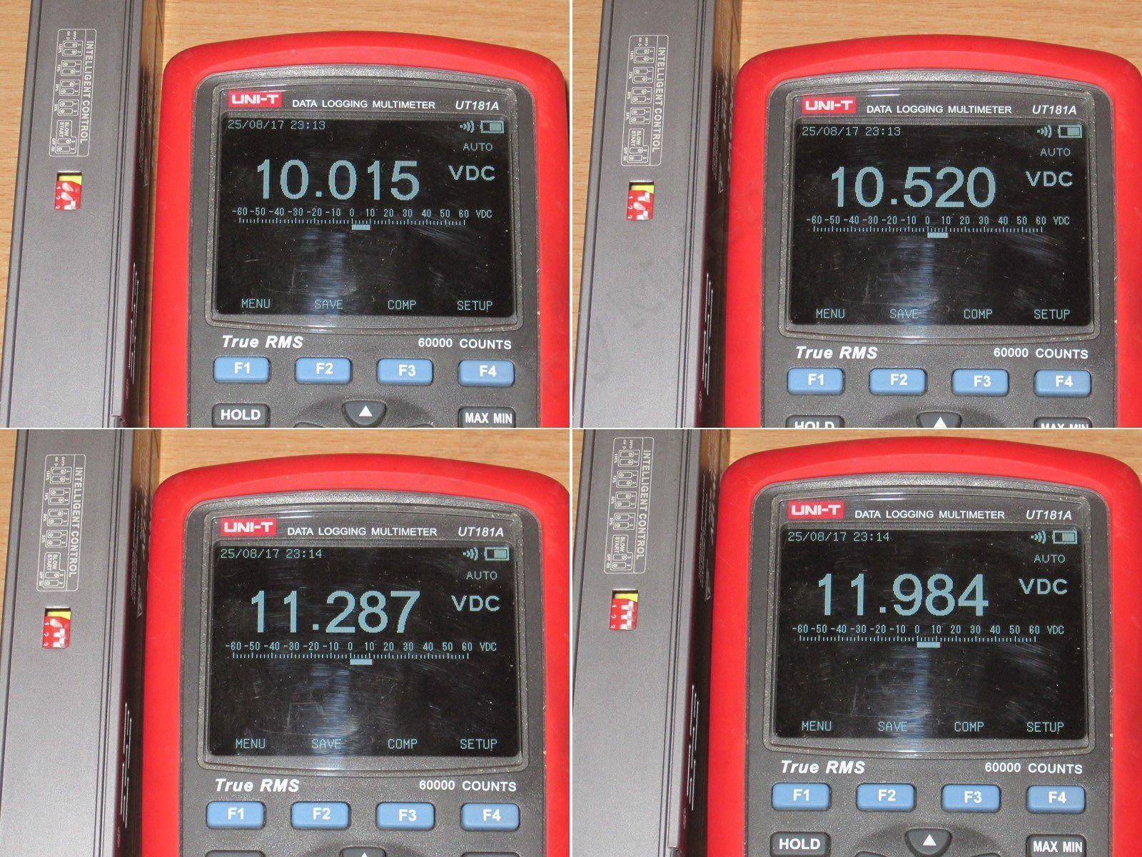
During soft start, the power supply quickly raises the voltage to about 7–7.5 V, then gradually brings it up to the selected level—in this case, 12 V (100%). The whole process takes about 5 seconds.
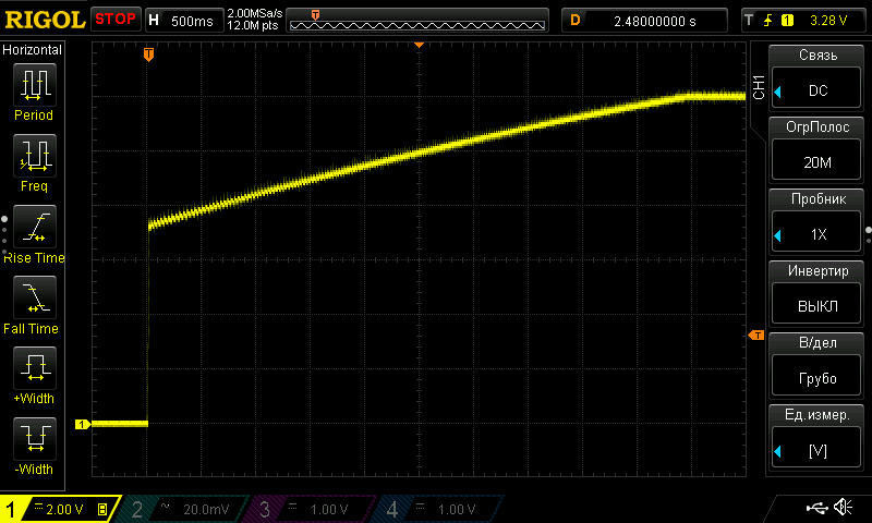
For the test, I used one of the loads from the new series and connected it using a four-wire setup to improve the accuracy of the efficiency measurement.
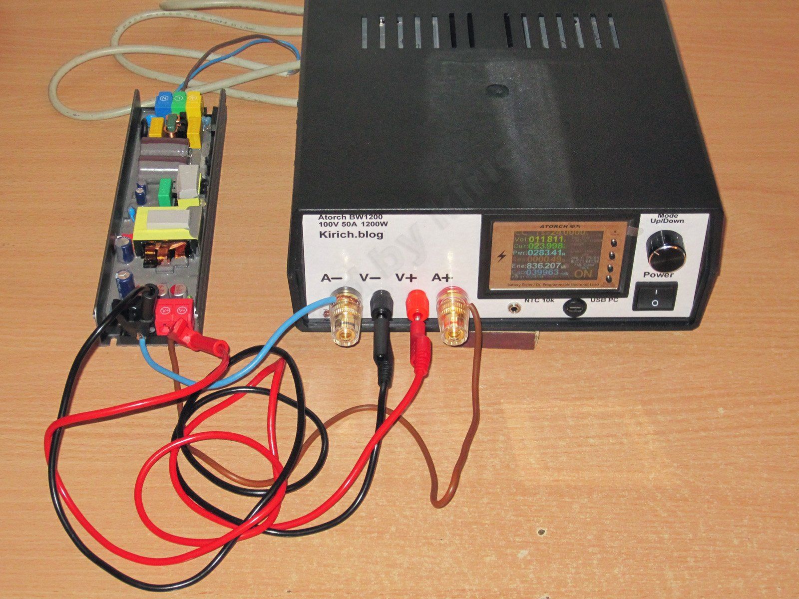
The graph still came out a bit wonky, but never mind. A better measurement instrument should arrive soon, because this one has really been getting on my nerves.
Efficiency is about 91% over the 1–25 A range. It could be better, but overall I like it.
The power supply’s protection trips at about 25.5 A, practically right at the rated maximum. In my view, that improves reliability, although I’ll get ahead of myself and say that based on the test results, I’d raise the threshold a little, to about 27 A.
High-frequency ripple. I messed up the scale a bit here, sorry about that. I didn’t redo the measurement.
The main point is that the peak-to-peak ripple across the entire range is about 250–300 mV at most, which is perfectly normal for power supplies with this much power and voltage.
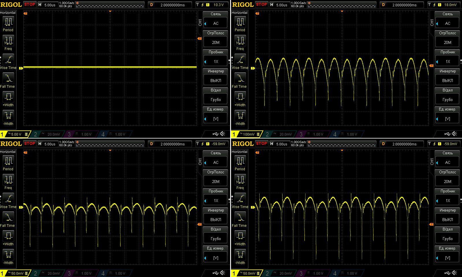
The low-frequency ripple test gives a clearer picture. First, the peak-to-peak ripple is no more than the same 250–300 mV. Second, there’s a little 100 Hz ripple showing through. It looks pretty rough on the graph, but keep in mind the scale is only 50 mV per division, so it’s perfectly acceptable.

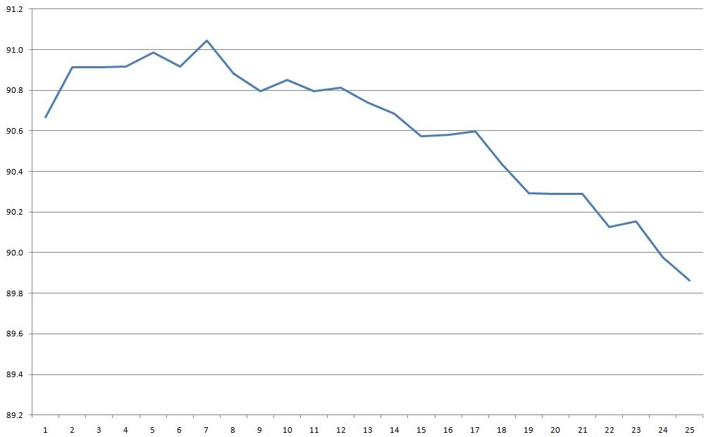
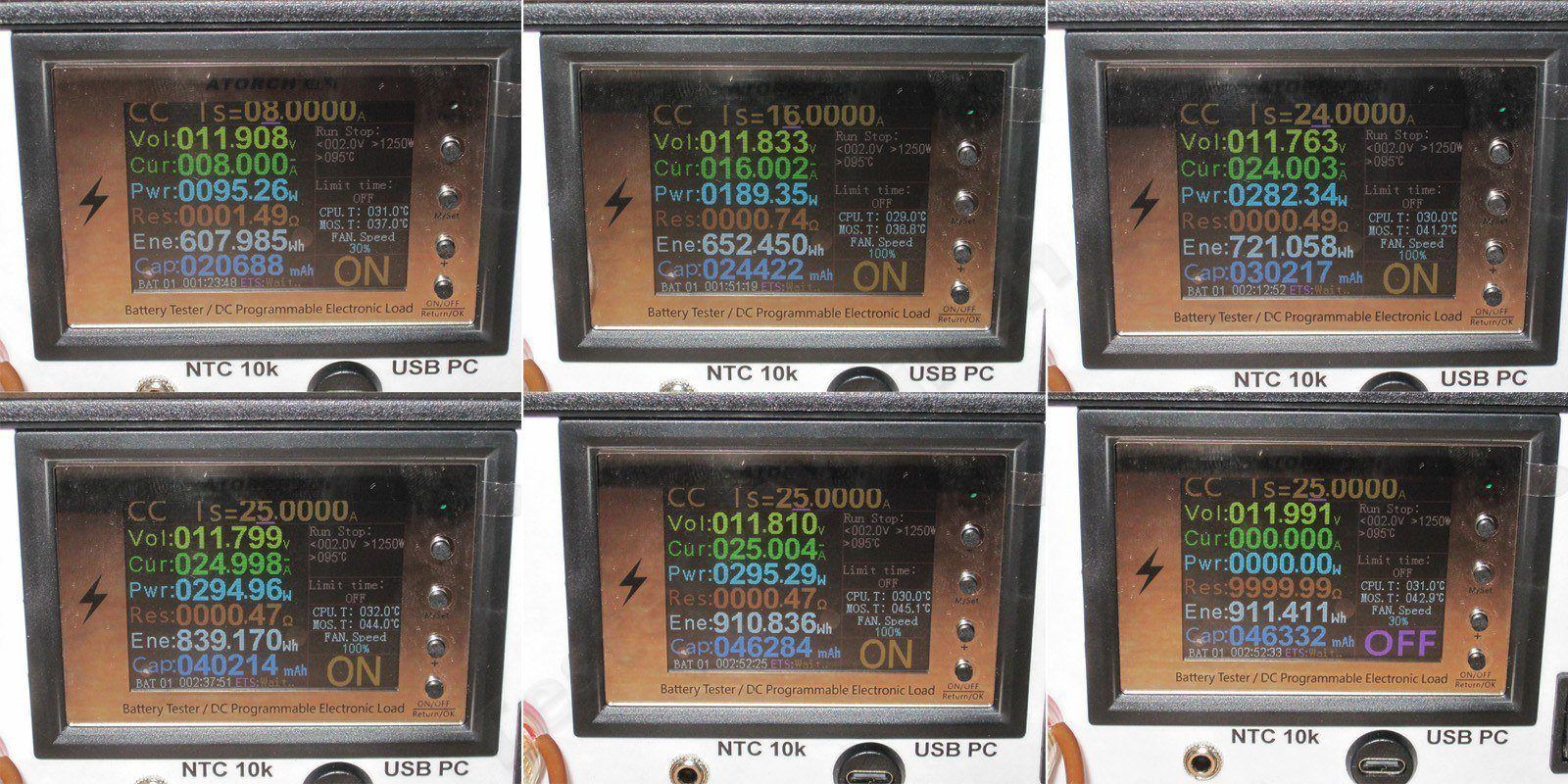
The test was run in stages of about 20 minutes each (often longer) at 8, 16, 24, and 25 A. I ran the last test separately because the current was right up against the protection limit.
The initial voltage was about 11.908 V. As the load increased and the unit warmed up, it dropped; with the power supply hot and under full load, it was 11.81 V. After removing the load, it rose to 11.991 V. The last two photos show the unit hot, under load and with no load.
The voltage-versus-current behavior may have been affected by voltage drop across the terminal block. The power supply also has a positive temperature coefficient, but overall the results are quite satisfactory.
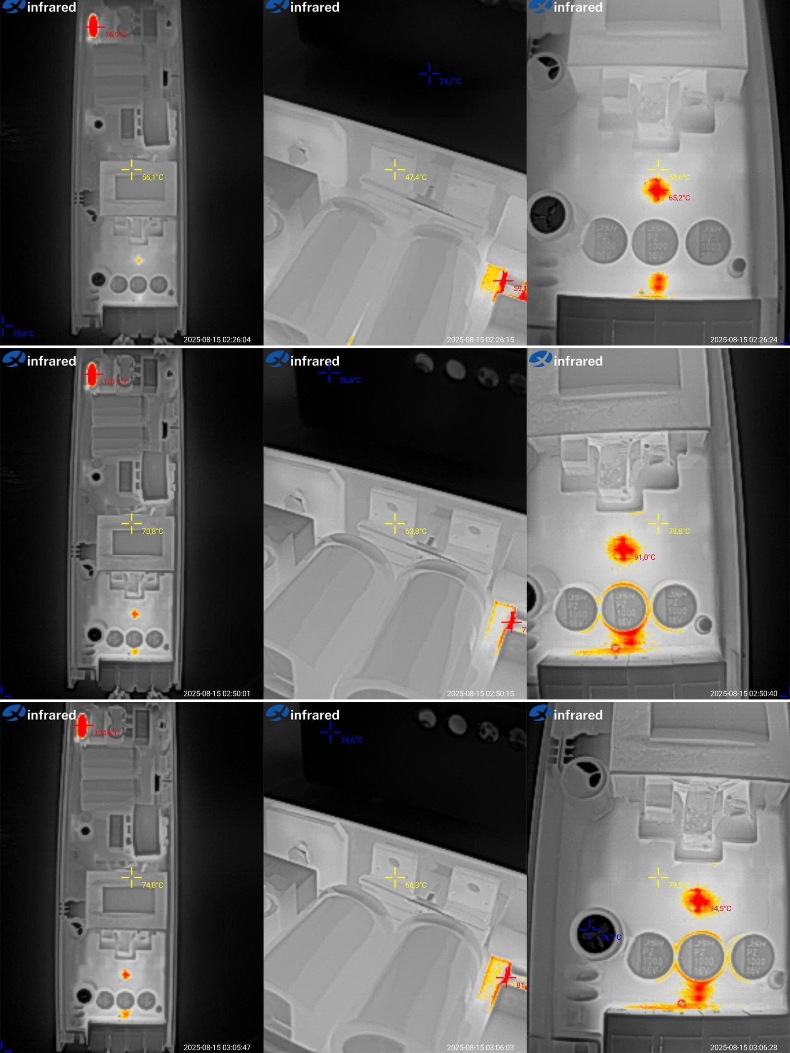
And now the temperatures.
Results after testing at 16, 24 and 25 A.
Even at full load, the transformer was at 74 °C, the input transistors at 66 °C, and the output transistors at 80 °C. Oddly enough, the hottest component, at around 95 °C, was the synchronous rectifier controller.
The second power supply, LS-400W-12V — link.
Rated at 12 V, 400 W, 33 A.
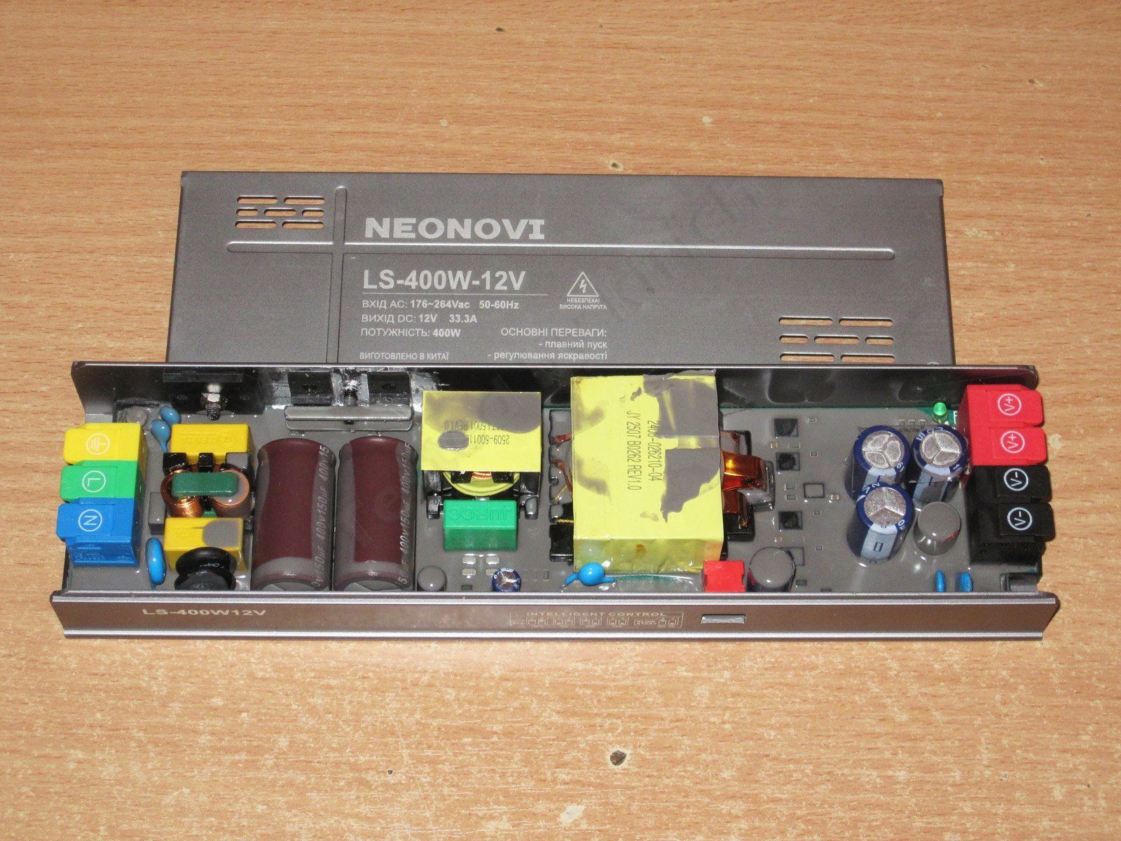
Essentially, the manufacturer just increased the capacitor capacity and the power ratings of the inductor and transformer. The input diode bridge is different too, but overall the units are very similar.
The synchronous rectifier transistors are different here, though. The previous unit had ZTG020N04; this one has ZTG014N04. I couldn't find the datasheet right away, but I assume the first ones have an on-resistance of 2 mΩ and the second ones 1.4 mΩ; both are rated for up to 40 V.
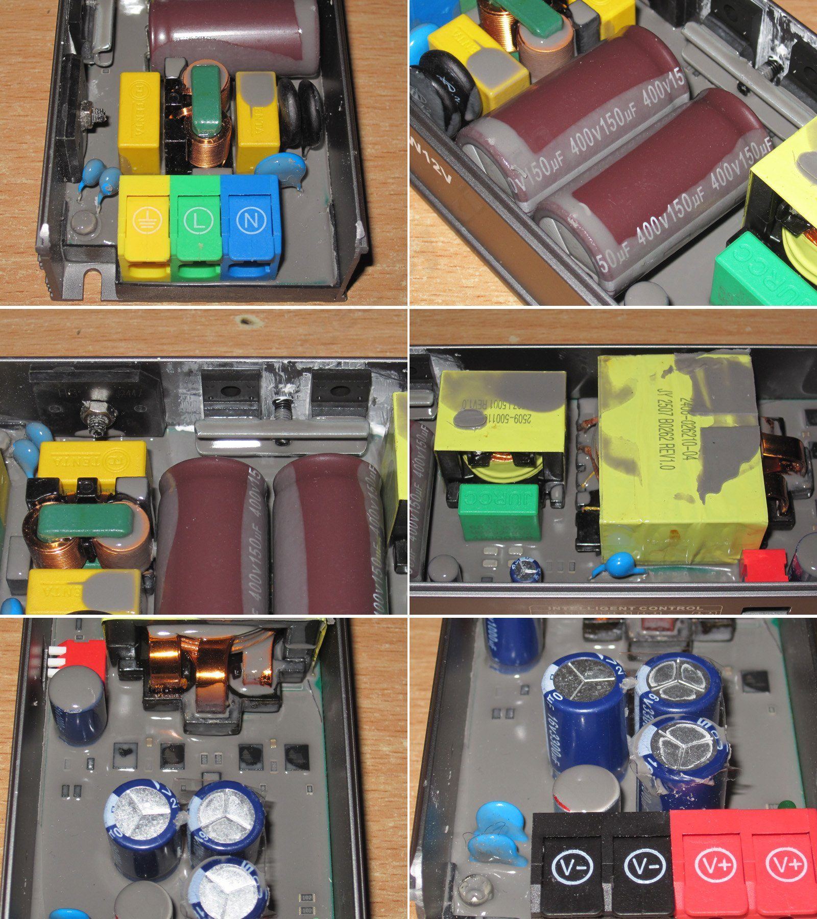
I just couldn't resist adding some photos of the transformer. It's beautiful :)
Especially the secondary winding, made from a pair of copper busbars.
And here's a side-by-side photo of the internals of both models, to show why the 400 W model is longer.
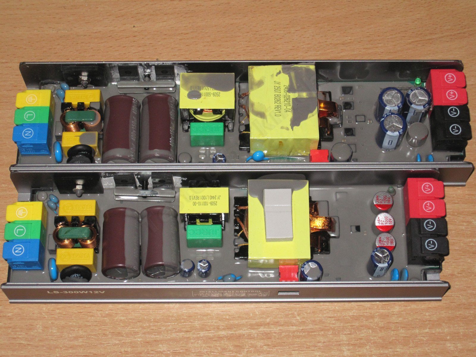
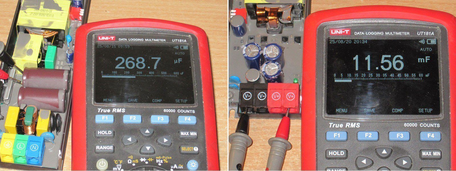
The input filter capacitance is about 270 µF, or 135 µF if you go by the 150 µF rating printed on the capacitors. That's perfectly normal.
The output capacitor configuration has changed: there's one 100 µF polymer capacitor, with three 3300 µF capacitors in parallel with it, for a total capacitance of about 11,000 µF. They're all rated for 16 V.
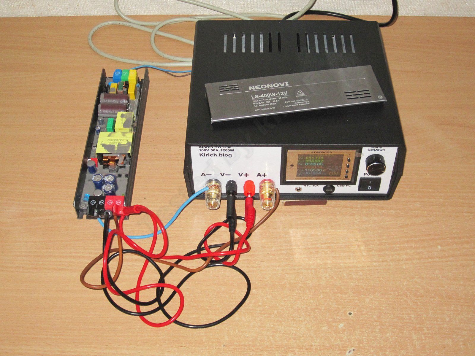
The same electronic load was used for testing, with a maximum current of 50 A and power up to 1200 W.
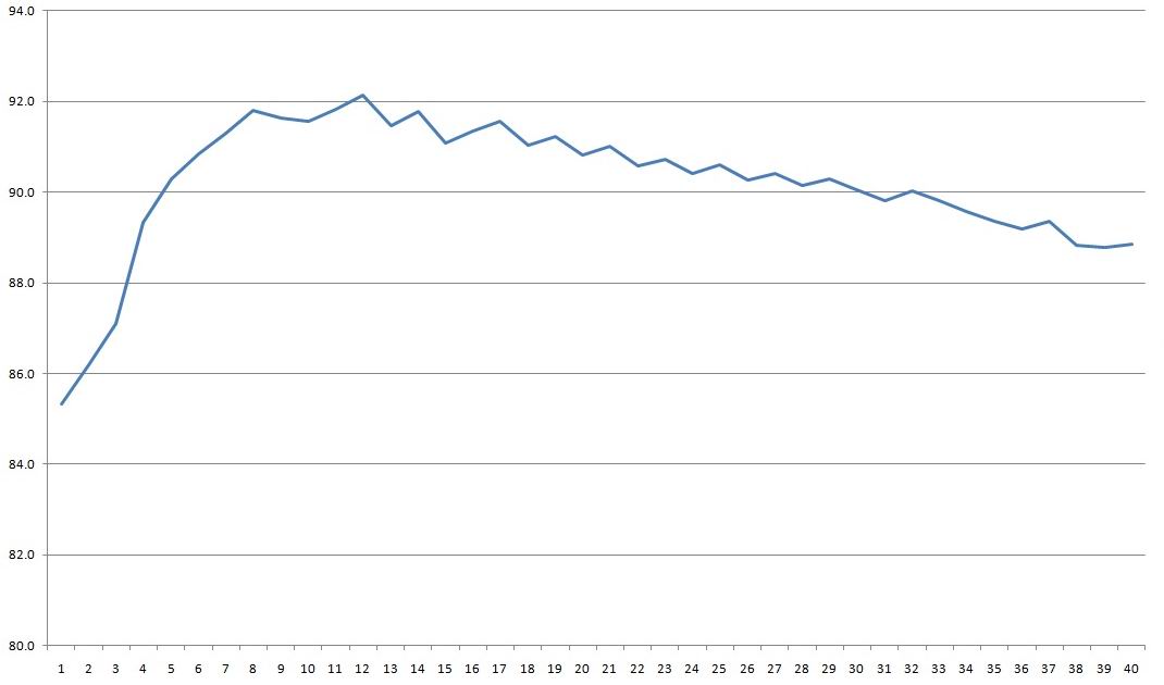
Efficiency was even a little higher here, around 91–92%, but it peaks at about 150 W and then drops, while still remaining relatively high.
Efficiency was measured over the 1–40 A range.
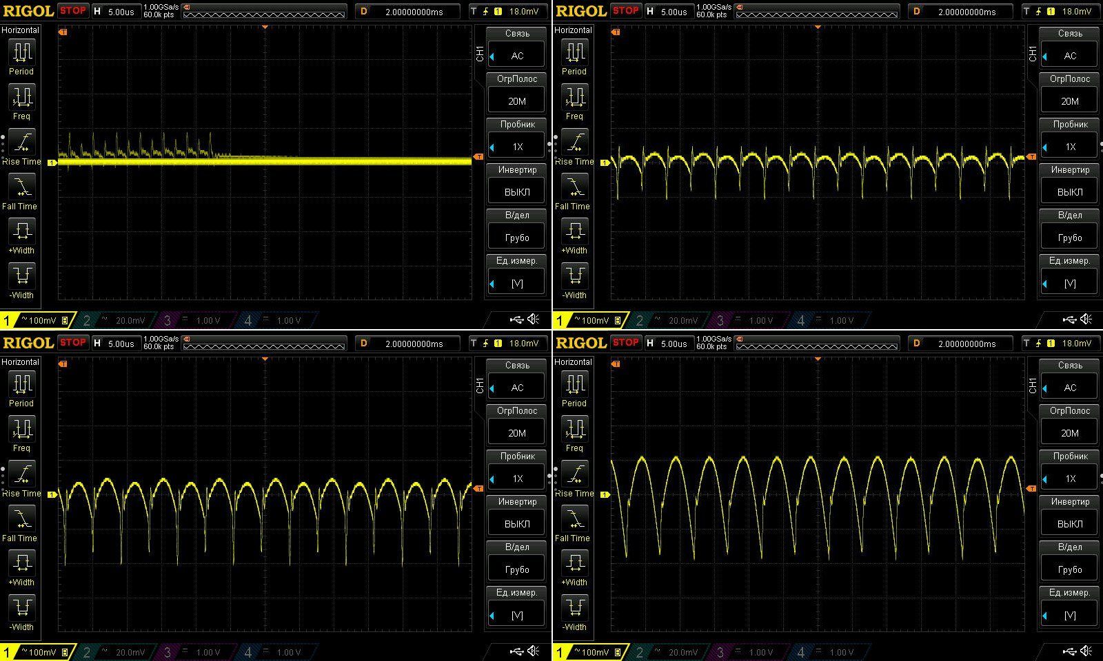
High-frequency ripple was up to about 300 mV, which is also normal for power supplies with comparable power and voltage ratings. And given that there's no output filter here, it's perfectly fine.
As usual, measurements were taken with no load and at 33%, 66% and 100% load.
Low-frequency ripple reached 400 mV peak-to-peak, and at full power the 100 Hz ripple became quite noticeable. These results are satisfactory. They could be improved a little by increasing the input capacitance, but it's fine as is.
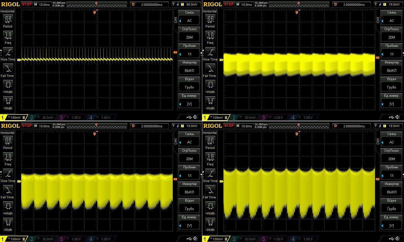
Operation under load.
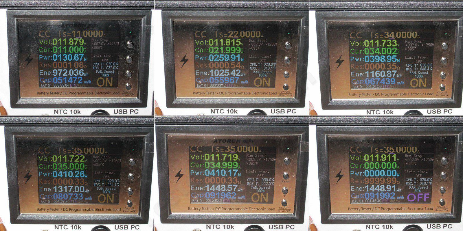
With no load, the output was 11.879 V. I then increased the load current in steps to 11, 22, 34 and 35 A. At the last setting, the unit delivered 410 W, despite its 400 W rating. The last two photos show the power supply hot, under a 35 A load and with no load.
The voltage regulation under load is quite satisfactory (especially considering the voltage drop across the terminal block), and the temperature regulation is excellent.
You may be wondering why I didn't mention the maximum protection current earlier. First, it turned out that the load's maximum current of 50 A wasn't enough to find it. Second, the power supply failed this test.
We contacted the manufacturer, who replied that they try to set the protection current to 1.3 times the maximum rated current. But 50 A compared to 33 A is clearly not 1.3 times; it's closer to 1.5. And the principle of “the more, the better” doesn't apply here: the protection current should only slightly exceed the rated maximum, typically by 10–20%. But you also need to take temperature into account. If the power supply gets very hot, the protection current should be set just below the limit, or you should definitely install a temperature sensor.
In any case, I’ve informed the manufacturer. While I was at it, I asked why the 300 W model has thermal pads between the cover and the transformer and inductor, while the 400 W model, which runs hotter, doesn’t.
Here’s a photo of the 400 W power supply delivering almost 600 W.

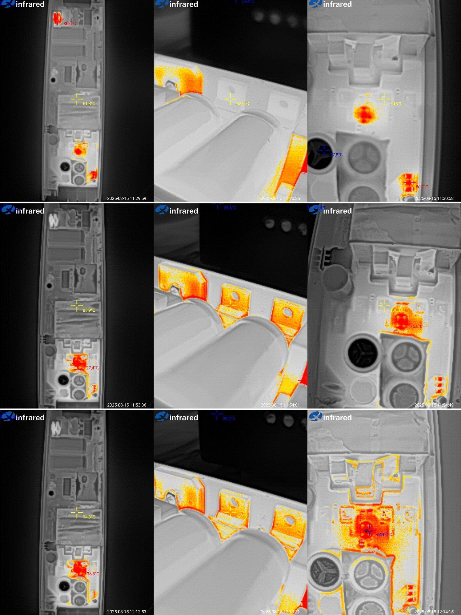
Temperatures at output currents of 16, 34, and 35 A. As usual, we’re interested in the maximum readings.
Transformer: 94 °C (which is exactly why it could use a thermally conductive pad); transistors: 86 °C, which is fine (the diode bridge in both power supplies was at roughly the same temperature); output transistors: 123 °C, which is a lot; and the synchronous rectifier controller went over 130 °C.
I suspect the output transistors here are “stiffer,” i.e. they have higher gate capacitance, making them harder for the driver to control. As a result, the driver runs hotter, and the transistors themselves heat up more, in turn heating the driver even further.
Not exactly great. In my opinion, this power supply’s maximum continuous current is closer to 30–32 A.
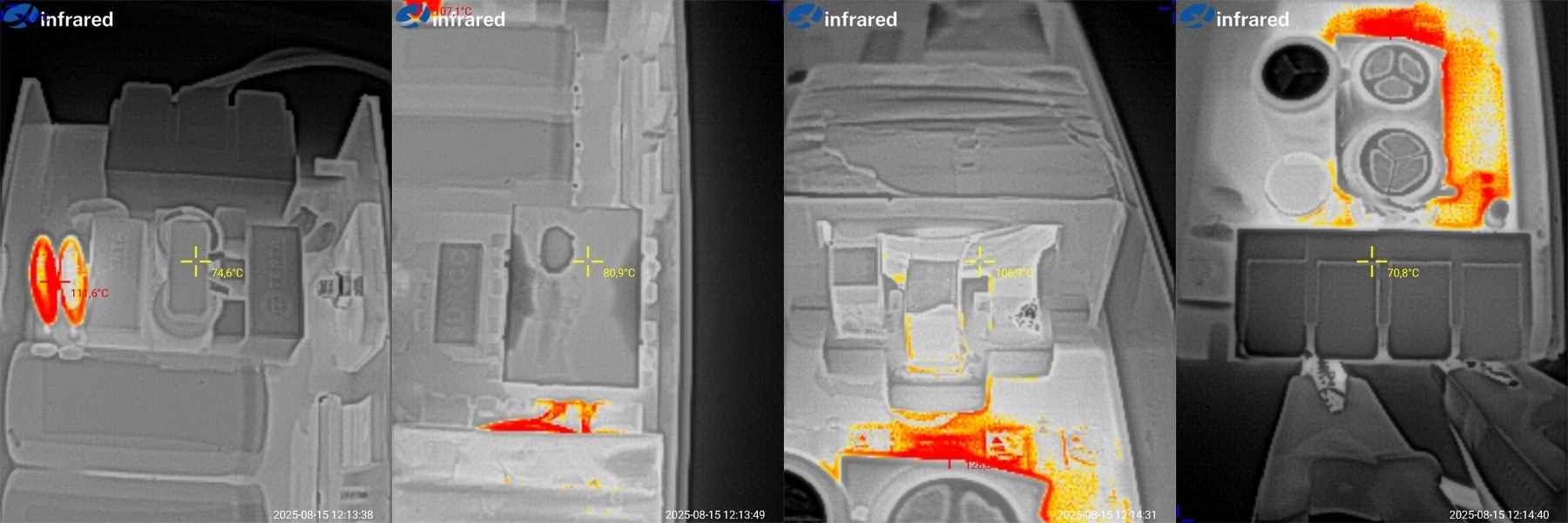
I also took temperature readings of the other components.
1. Input thermistors: 111 °C, which is normal for them. Input inductor: 74 °C, also fine.
2. Inverter inductor: 81 °C, excellent.
3. Winding temperature: 110 °C, acceptable, though it could be lower.
4. Output terminal block: noticeably hot, with a maximum measured temperature of about 74 °C. It looks like the terminals are rated for 16 A each, giving a total maximum current of 32 A. For a higher load, there should be 3+3 terminals.
Conclusions.
I’d call both models good, if it weren’t for a few “buts.”
The 300 W model is essentially faultless: the protection is set up properly, temperatures and ripple are within spec, and I also liked the components and build quality. In fact, I think it’s an excellent power supply. You could nitpick, but honestly, I don’t want to.
The 400 W model could have been pretty good, if not for two issues: it runs relatively hot at currents above 32 A, and the protection threshold is set incorrectly. I never managed to reach it, hitting the 50 A output limit first. Subjectively, if you adjust the protection current, it would make a good 350 W power supply.
And then there’s the price: around $14–15 for a quality 300 W model, even without a fan, is pretty good in my book.
That’s it for the 12 V models for now; the 24 V versions will follow a little later. I hope you found this interesting. As always, I’ll be glad to read your comments, and thanks to Vitaly for providing the samples.
593.90 ₴
This page was found when searching for:
https://www.kirich.blog/obzory/bloki-pitaniya/1283-dva-bloka-pitaniya-12-volt-300-i-400-vatt-interesnyh
https://www.kirich.blog/obzory/bloki-pitaniya/1283-dva-bloka-pitaniya-12-volt-300-i-400-vatt-interesnyh
This model is included in the summary table: Comparison of power supplies: ripple, efficiency, and temperature rise
The figures from this review are in the measurement database: Power supplies
Calculate manuallyAll calculators
Discounted products
You may be interested in



Discounted products
Support the project
All the content on the site and the advice are free, but we’d be grateful for your support of the project and the channel!
Discuss on the forumHave a question or some experience to share? Discuss the article with the author and readers: the forum is a convenient place to share schematics and photos.
Go to the forumOnly registered readers can comment. It takes a minute to sign up, and you can log in with the same account you use on the forum.
Log inRegister