
Four more power supplies: 60, 100, 200 and 400 watts, 24 volts
227.87₴
A reminder: to keep up with new posts on the blog, I recommend following me on Instagram. I’ll post notifications about every new article there, and might also write about something interesting from time to time - link to my account
You can also subscribe to updates and new articles on the Telegram channel - https://t.me/KirichBlog
These are essentially power supplies from the same product line as the previous ones, but only one has the same power rating: the 400-watt model. That’s a good thing, since it lets us cover a wider range of 60, 100 and 200-watt models, and compare the 400-watt, 24 V version with the 400-watt, 12 V version.
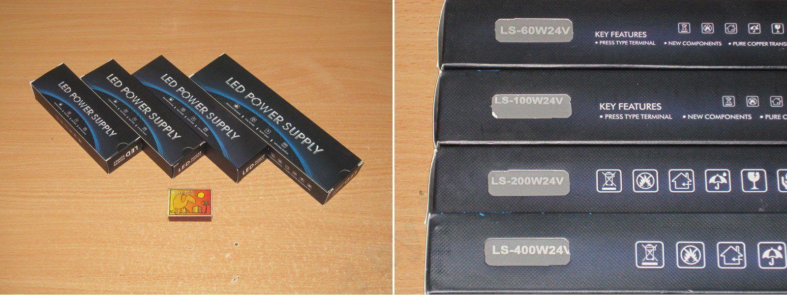
The design is identical to the previous models, and I personally like it: neat and understated.
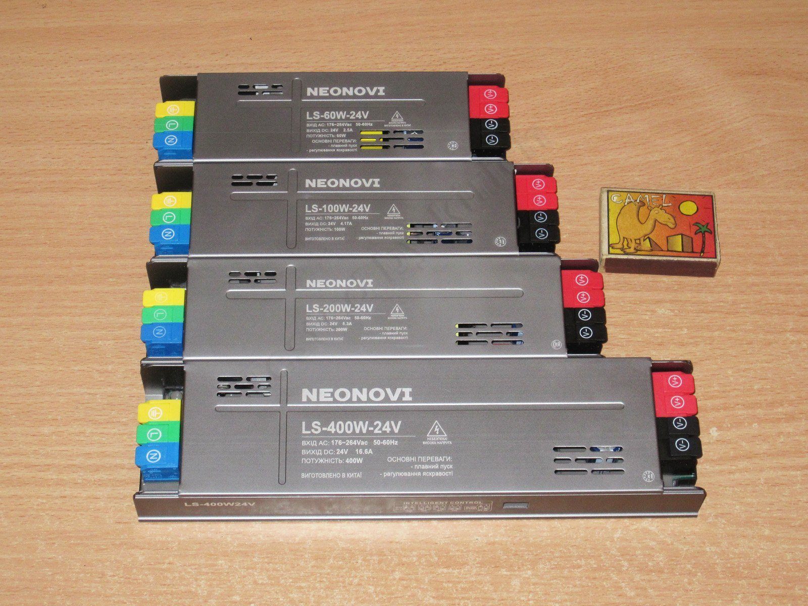
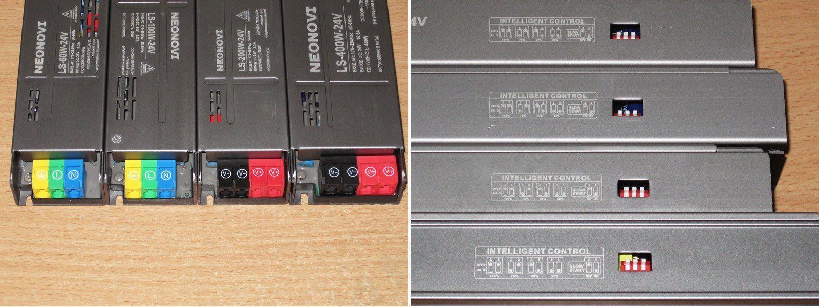
The same terminals and the same operating mode switch.
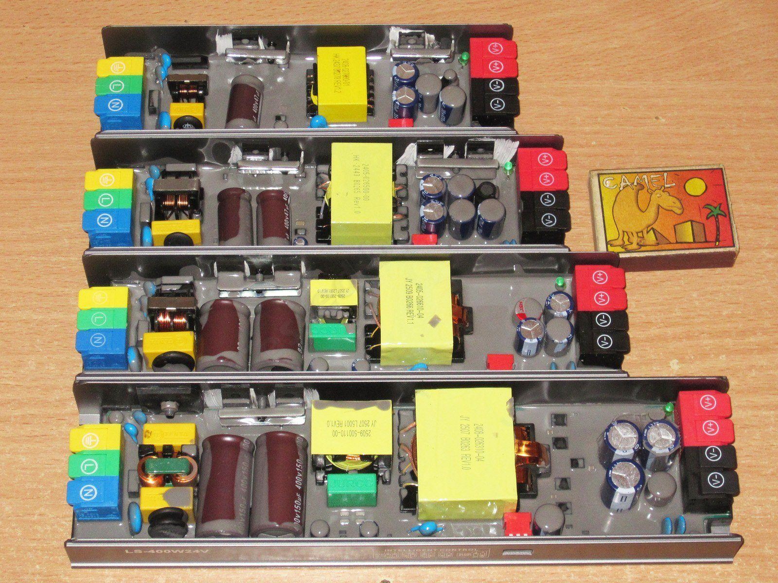
So you don’t have to hunt through the review later, here’s a group photo of all the units with their covers off, for comparison. I should say right away that the build quality is pleasantly impressive: neat work, good quality, branded components. It’s clear these power supplies were designed with a long service life in mind, and at this point I’m pleased. Though there’s that green live terminal again—it really bugs me....
Let’s start with the smallest model, the 60-watt LS-60W-24V - link
In my experience, the smaller models usually have the fewest problems with heat. In that respect, it’s a bit like living organisms: compare the ratio of the weight an ant can carry to its body mass with that of an elephant.
The topology is clearly single-switch flyback, which is more than appropriate for this power rating. The specified input voltage range is 176-264 V, but I’m almost certain it will also work fine from 115-120 V.
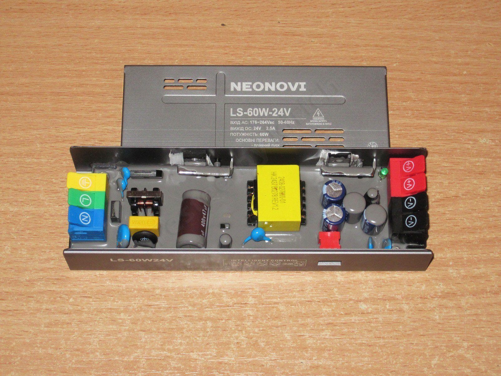
1. There’s an input filter, and you can also see the varistor here. I’ve already removed the sealant from it; the exact same varistors are used in all the power supplies in this series.
2. The input capacitor is 47 µF, which is enough for a 230 V mains supply, but a bit low for 115-120 V. In that case, I recommend reducing the load power.
3. There’s a Y capacitor. There’s also a small flaw in the potting nearby, leaving a small area of the board exposed.
4. There are four 470 µF, 35 V output capacitors, plus an inductor to reduce ripple.
5. The high-voltage transistor is a 4N65, apparently rated for 4 A and 650 V. That’s perfectly fine; it’s mounted with thermal paste.
6. The output rectifier assembly is rated for 10 A and 200 V, which is more than enough for an output current of 2.5 A.
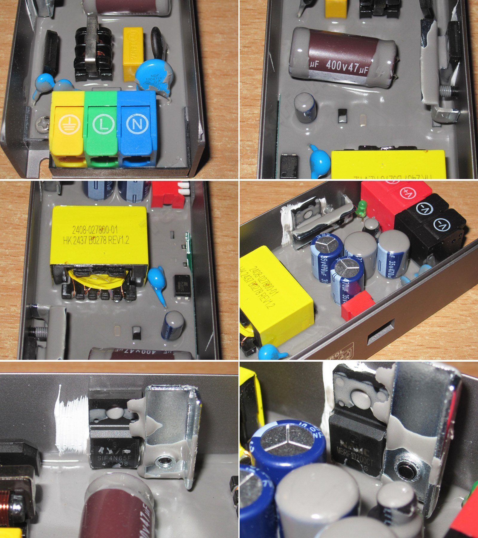
The input capacitor’s actual capacitance is closer to 42-43 µF, below the stated value but within tolerance.
The total output capacitance is 1357 µF, somewhat less than the expected 4 × 470 µF, which is odd. Usually, the output capacitors have measured higher than their rated capacitance. Still, this is plenty for this power supply, and using four small capacitors instead of one or two large ones is even better.
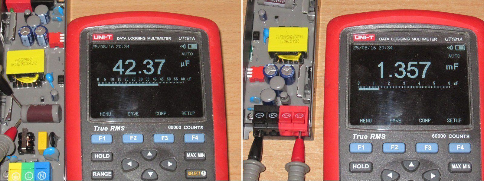
As with the 12 V models, this one has stepped output voltage adjustment. When used with an LED strip, the settings correspond to 25-50-75-100% of the strip’s power. The output is 24 V, so the intermediate voltages differ accordingly.

The soft start here takes 3 seconds instead of 5, which is a bit odd. If you power 12 V and 24 V LED strips from power supplies in the same room, they won't start up in sync.
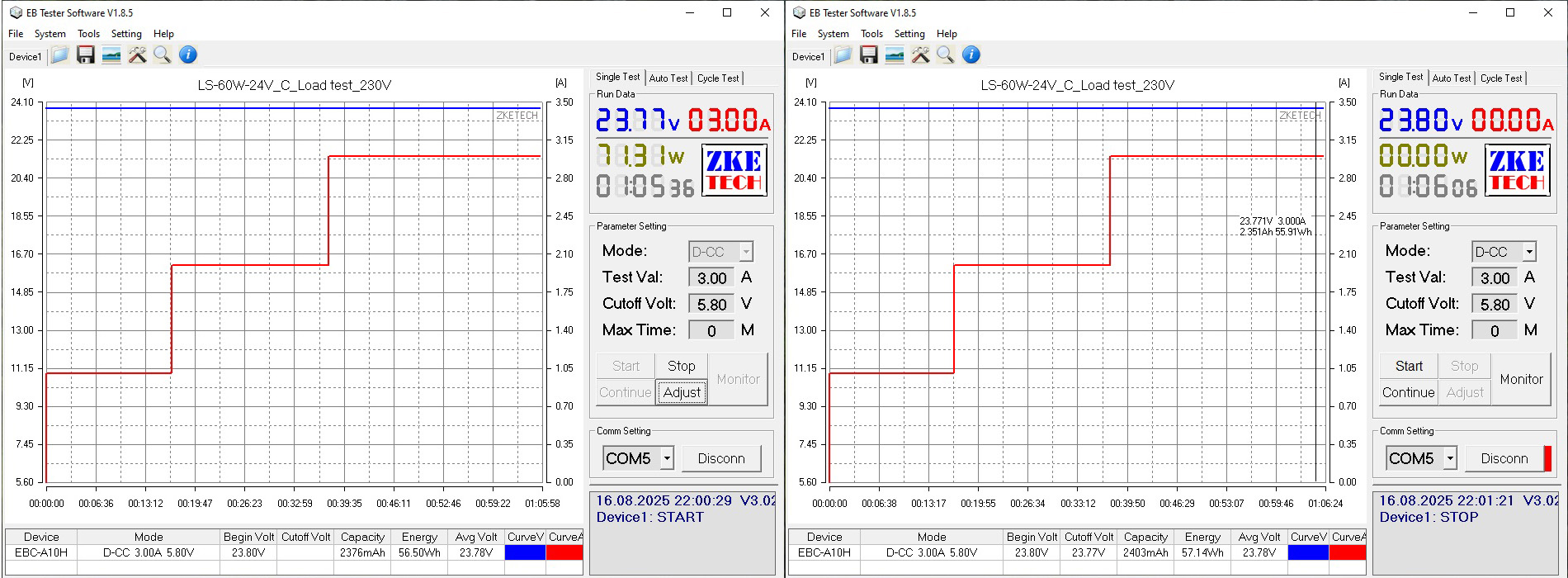
To test low-power supplies, I usually use a ZKEtech EBC-A10H electronic load. It's fairly convenient, although in some situations the lack of direct control on the fly is annoying.

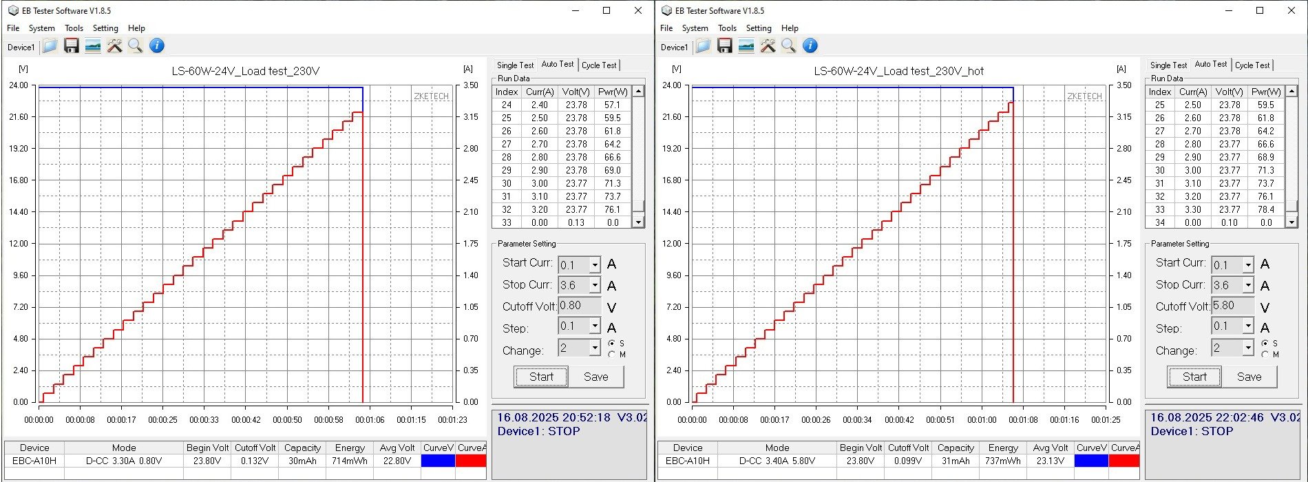
I checked the protection trip current in two modes, with the supply cold and warmed up. In the first case, the protection kicked in at 3.3 A; in the second, at 3.4 A. That's perfectly fine, although the current usually drops when the supply is hot.
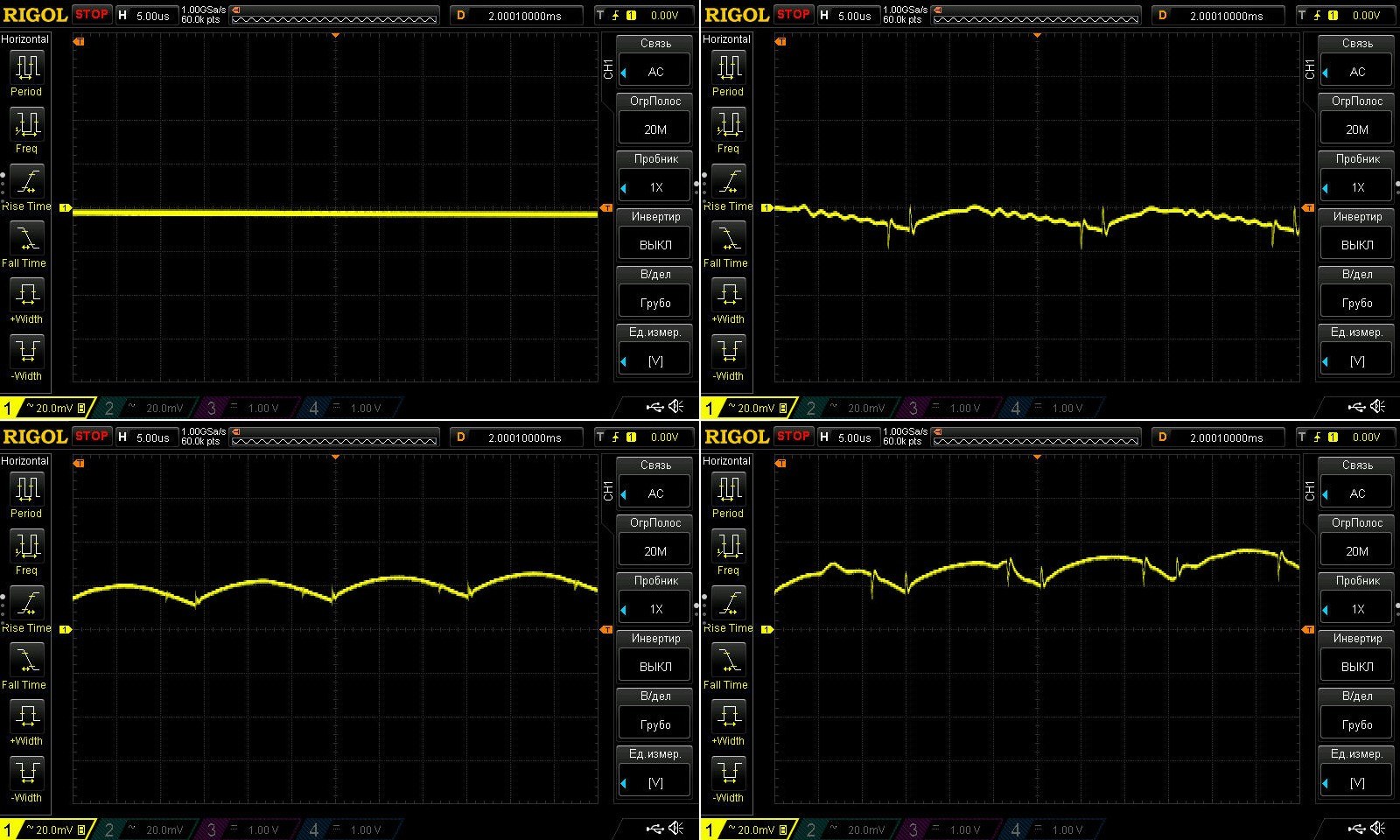
I checked ripple with no load and at currents of 1, 2, and 3 A. The maximum rated current is 2.5 A.
Overall, everything is excellent here: less than 20 mV peak-to-peak at 120% load.
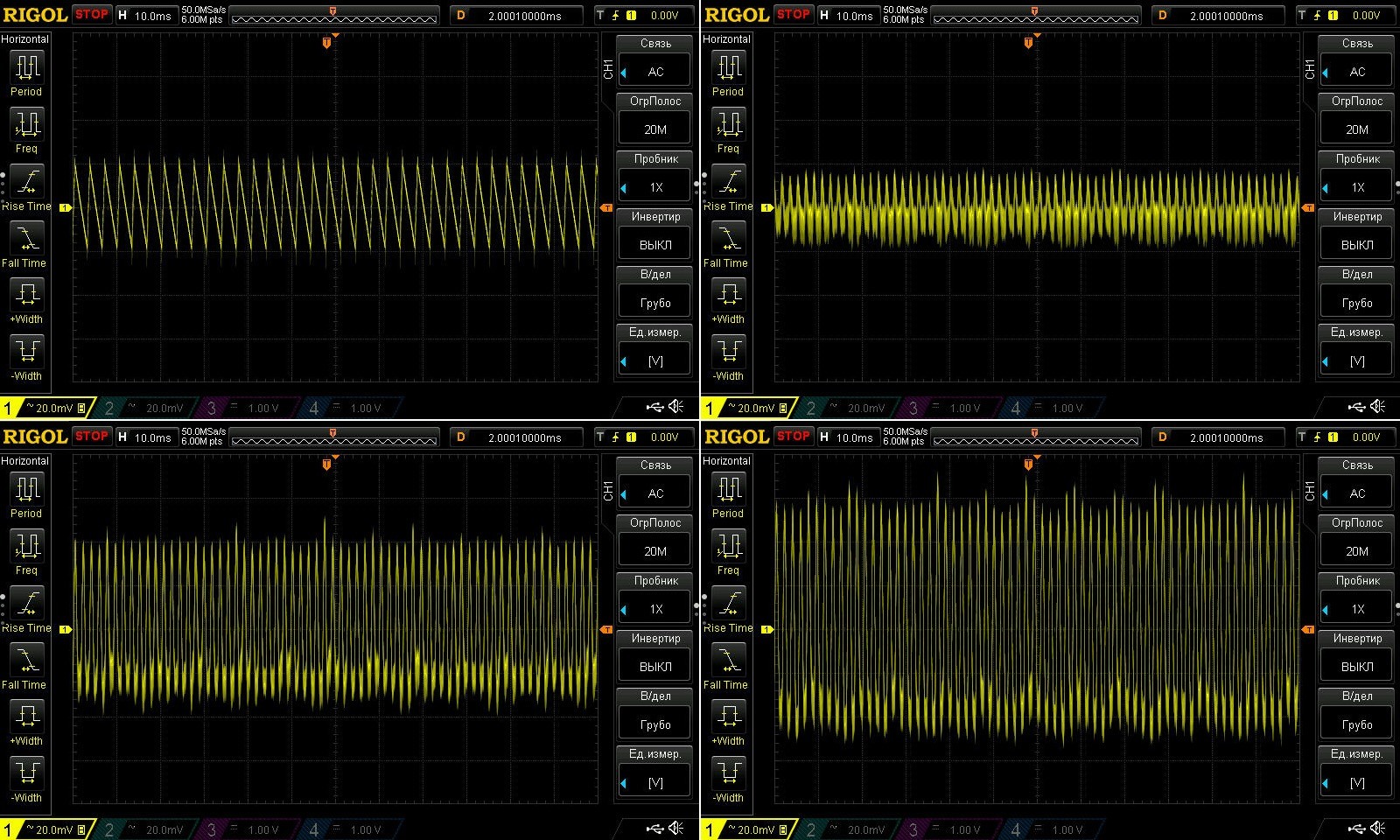
At low frequencies, the picture is completely different: the total peak-to-peak ripple is around 100–120 mV. But the strange thing isn't that—it's the waveform itself.
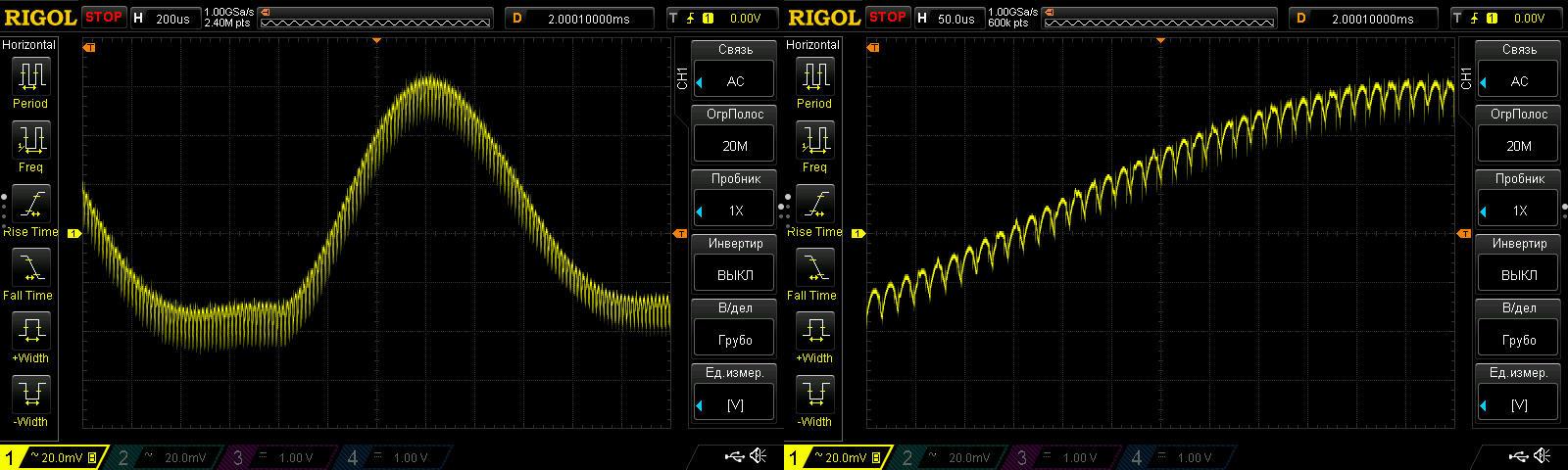
When I was testing the supply under different operating conditions, I noticed some strange ripple. You can already see in the first screenshots that the waveform is drifting upward.
Looking more closely, I noticed this pattern at the output: low-frequency ripple modulated by high-frequency ripple. This isn't really a problem for the load; I just don't understand what's causing it. At one point I suspected the load (this screenshot was taken using an Atorch CL24 electronic load), but when I tried the EBC-A10H shown above, I saw exactly the same thing. Later, I thought I could try loading it with resistors and compare the results, but I didn't.
So it's not exactly bad, I just don't understand why it's happening.
The test had three stages, each lasting about 20 minutes, at currents of 1, 2, and 3 A. As a reminder, the rated current is up to 2.5 A.
The second screenshot shows the voltage of the hot power supply with no load. And everything is excellent here too: it was 23.80 V at the start of the test, dropped to 23.77 V under load, possibly partly due to the voltage drop across the terminal block, then returned to the original 23.80 V after the load was removed.
Temperatures at 2 and 3 A. I'll comment on the readings at 3 A, which is 120% load.
The transformer was at 72°C, the high-voltage transistor at 54°C, and the output diode assembly at 57°C. An excellent result.

Next up is a slightly more powerful 100 W model, the LS-100W-24V - link
This model is very similar to the previous one, but with a bit more power.
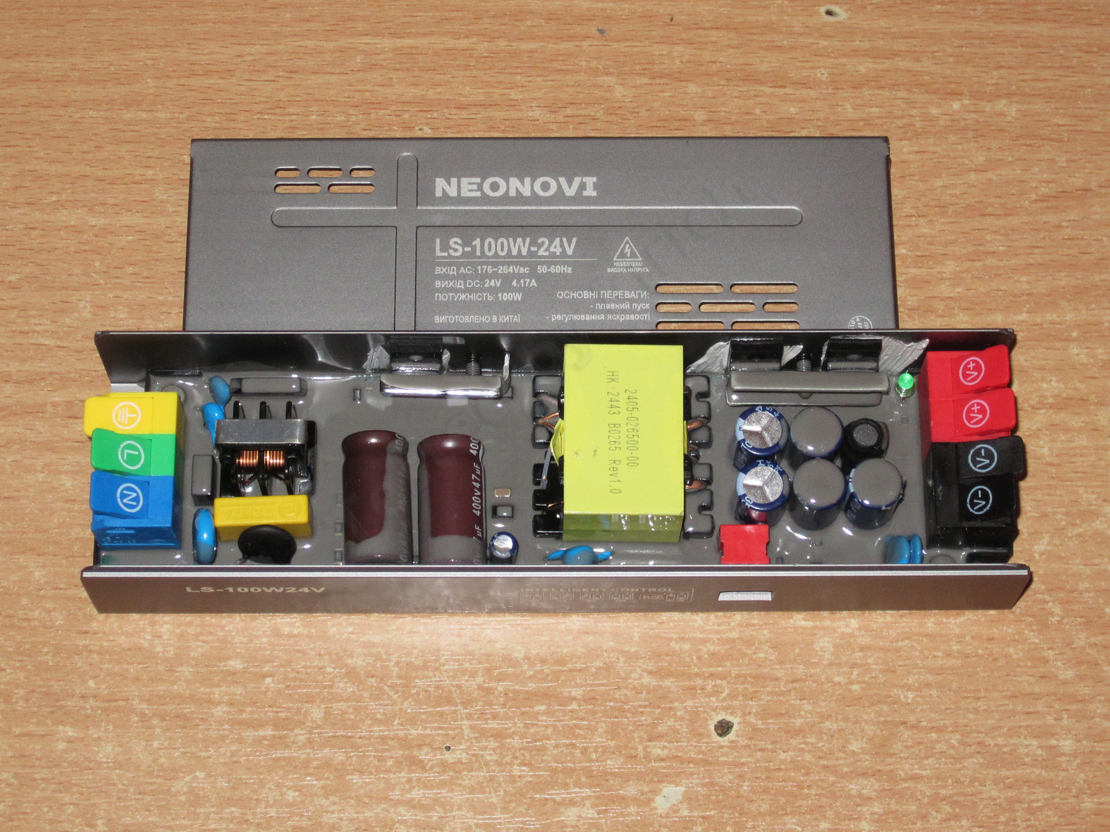
Basically, here's what we have:
1. There are now two 47 µF capacitors instead of one
2. A larger transformer
3. There are now two output diode assemblies
4. The capacitors are the same, 470 µF, 35 V, but there are now five instead of four.
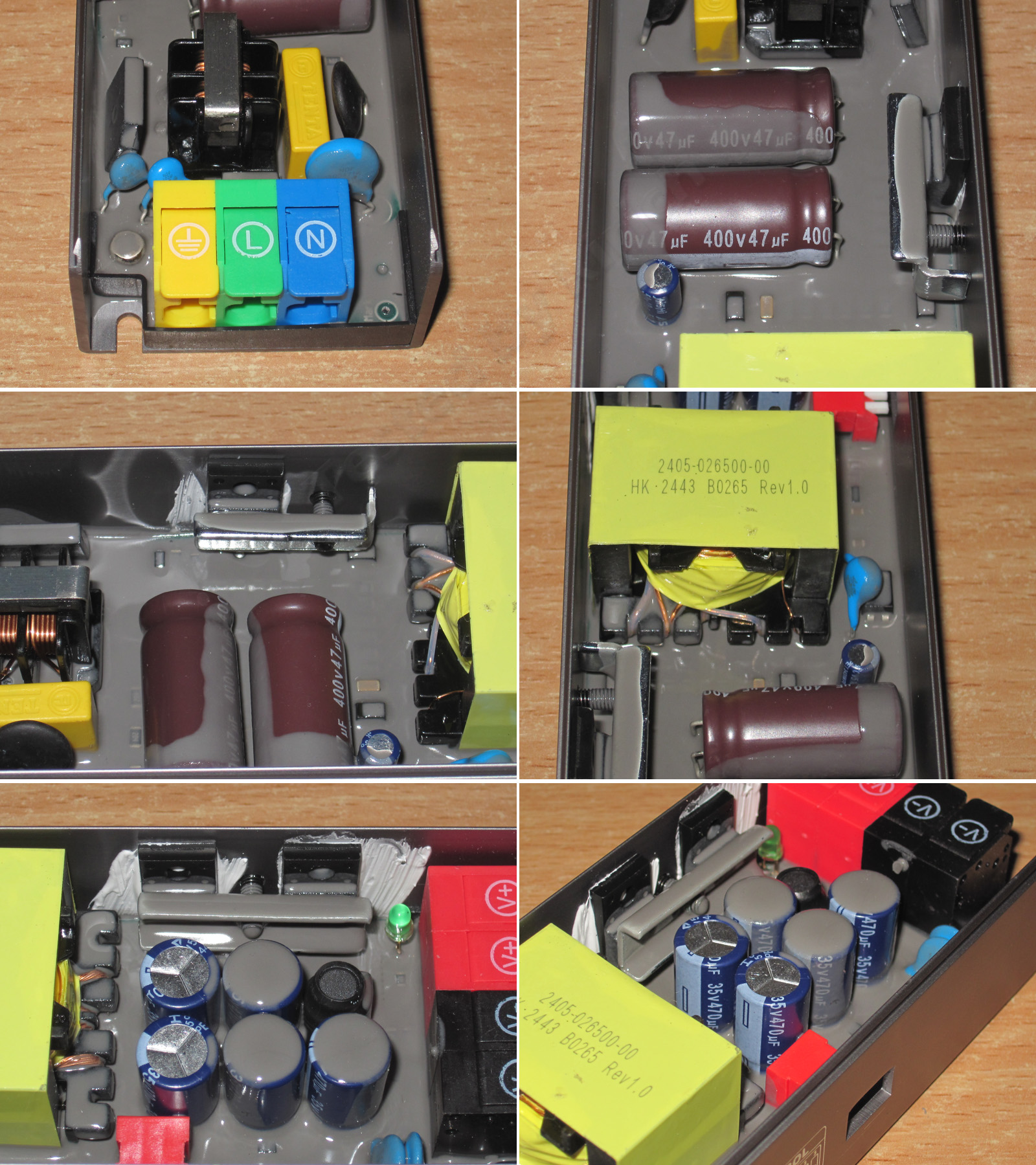
The high-voltage transistor is a 7N65, apparently rated for 7 A and 650 V; the previous one was rated for 4 A, so the rating has been increased in proportion to the power.
The previous model's diode assembly was already generously rated, but this one has two, giving a total rating of 20 A for an output current of 4.5 A.
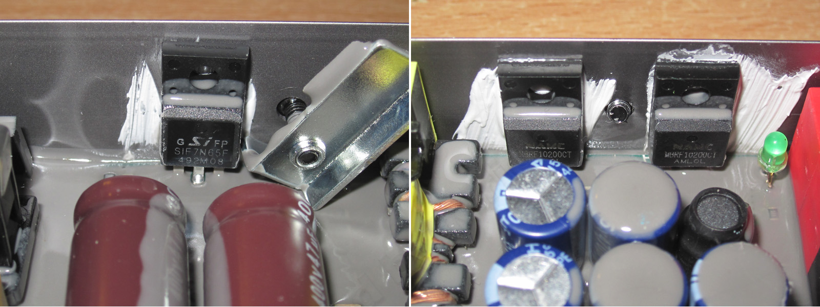
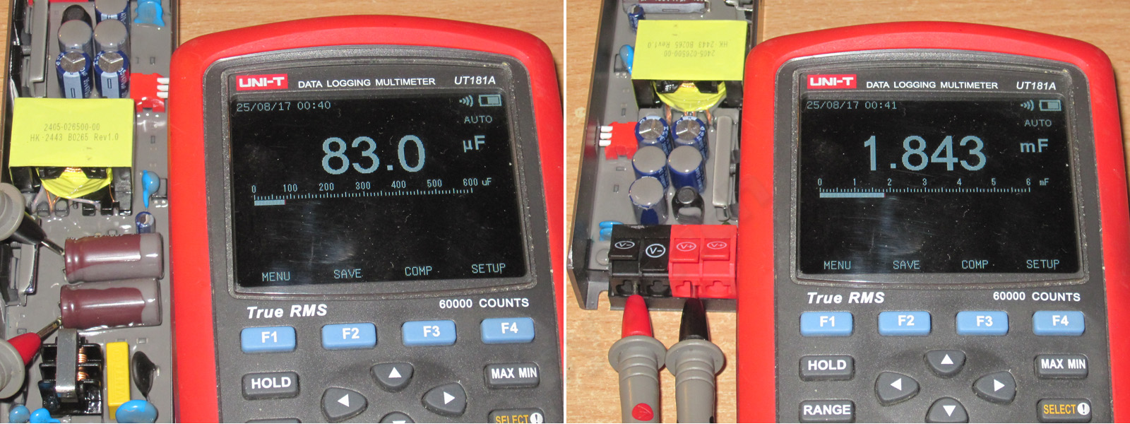
The total input capacitance is 83 µF, which is perfectly fine for 230 V, but still a bit low for 115–120 V and could affect the low-frequency ripple level.
The output capacitance is 1843 µF, which is generally fine, but again oddly low for five 470 µF capacitors, even though Aishi capacitors are considered a reputable brand.
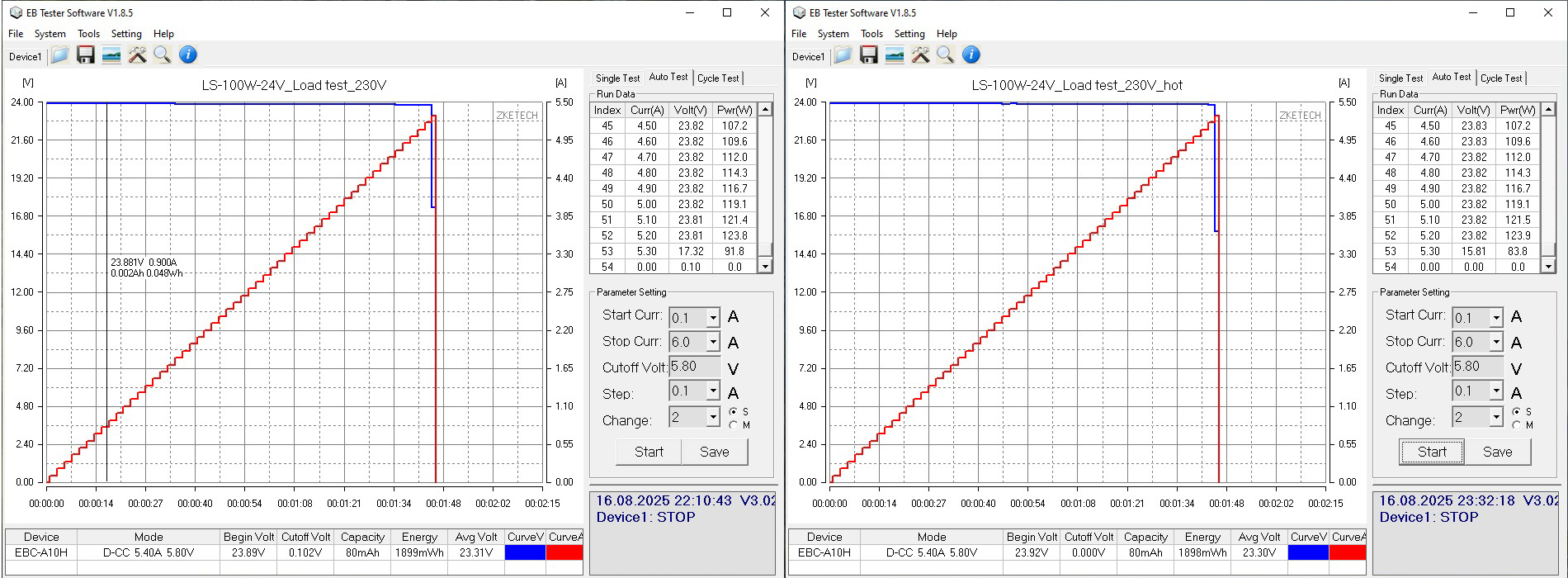
Whether the supply is cold or hot, the protection trips at around 5.4 A, which is about 20–25% above the rated power. I think that's exactly the right approach.
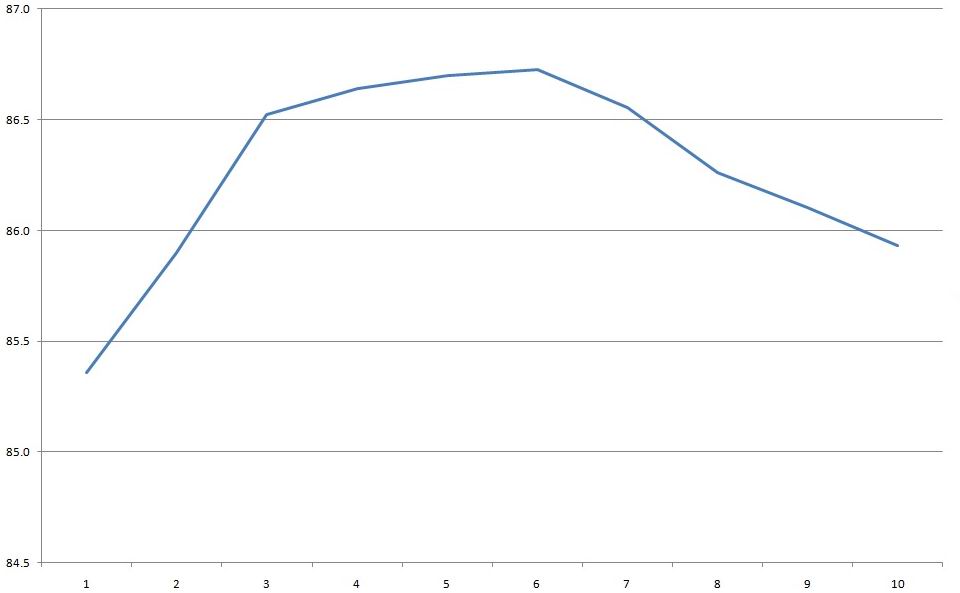
I also measured efficiency here. I don't do that with the lower-power models because the measurement accuracy is far too low. I got around 86–87%, which isn't exactly low, but it could be higher. The graph was recorded at currents from 0.5 to 5 A in 0.5 A increments.
I checked ripple with no load and at currents of 1.5, 3, and 4.5 A.
Yes, the peak-to-peak ripple is higher here, around 60 mV at 4.5 A, but it's still quite low.
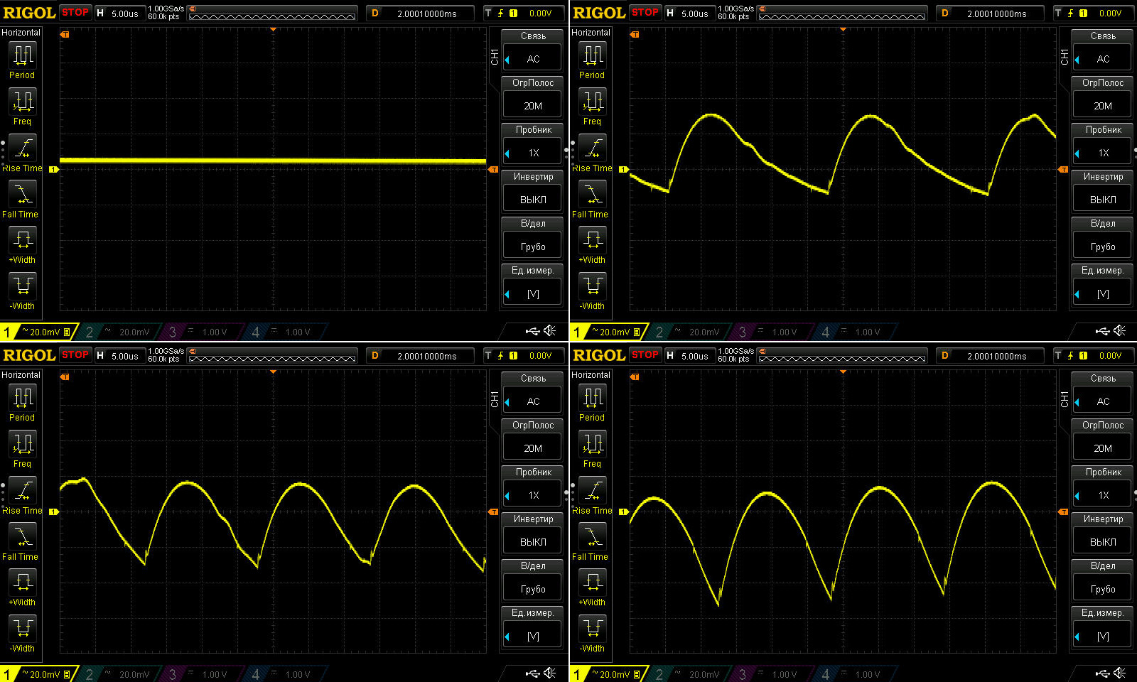
The low-frequency ripple is worse; basically, we're seeing the same situation as with the previous model. Again, the total ripple is about 160 mV, but since its shape is different, I don't think it's critical.
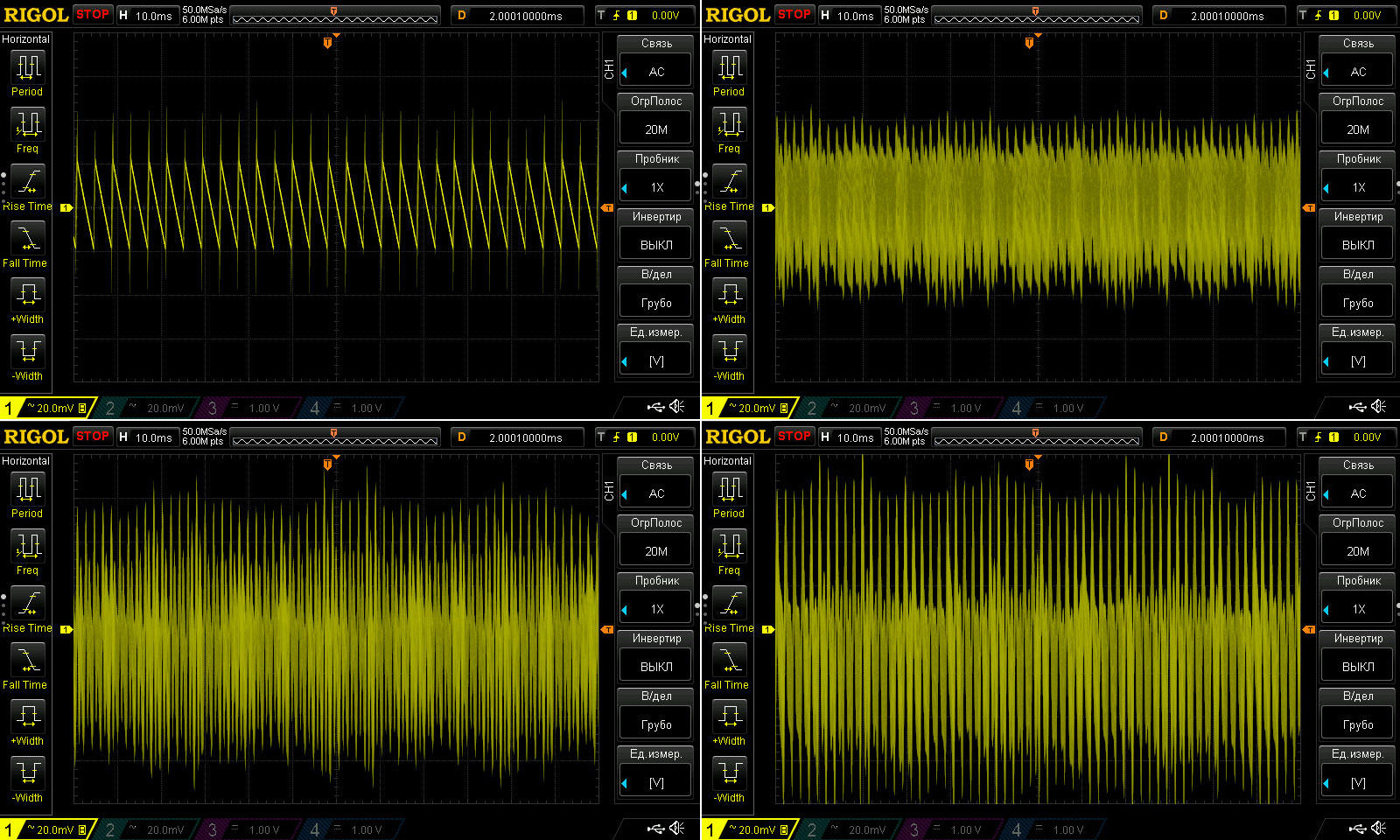
But this oddity is still bothering me. The left-hand screenshot shows that even the low-frequency component isn't chaotic, but repeats quite consistently. I'm starting to think this is just a characteristic of how the PWM controller works.

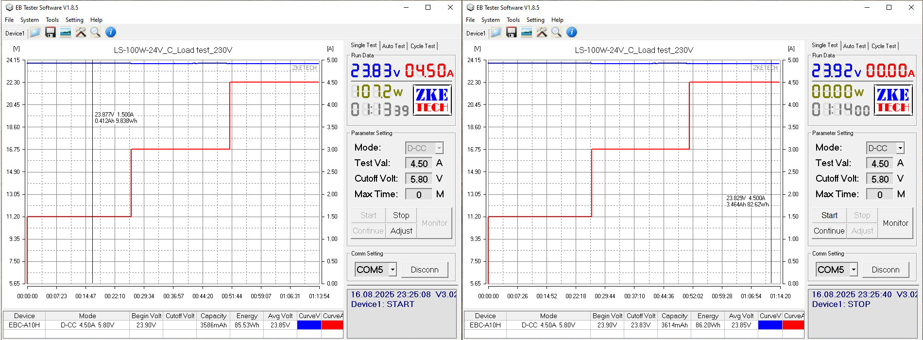
The load test was also conducted in three stages, at 1.5, 3 and 4.5 A, for about 20–25 minutes per stage. The maximum rated current is 4.17 A.
Here, the voltage varied by about 100 mV with load and about 50 mV with temperature, which is perfectly normal, especially since some of the voltage drop was across the terminal block.
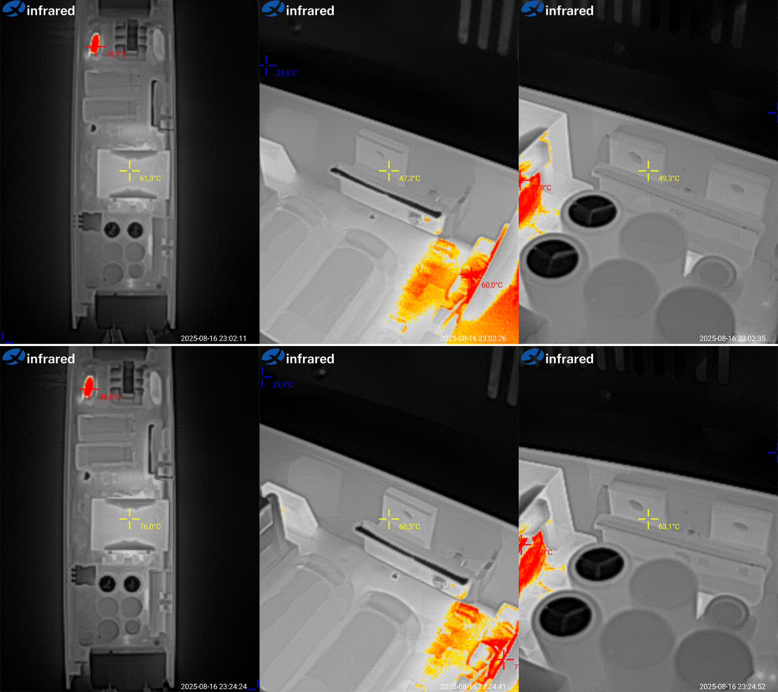
Temperatures at 3 and 4.5 A. As before, I'll also comment on operation at maximum power.
The transformer reached 76°C, the transistor 60°C, and the diode assemblies 63°C. Excellent results: even with a slight overload, the power supply has plenty of thermal headroom. I think it will work without any problems with a reduced input voltage of 115–120 V as well.
200 W model, LS-200W-24V - link
This one uses the same LLC topology as the 300 and 400 W models, but in a more compact form, so to speak.
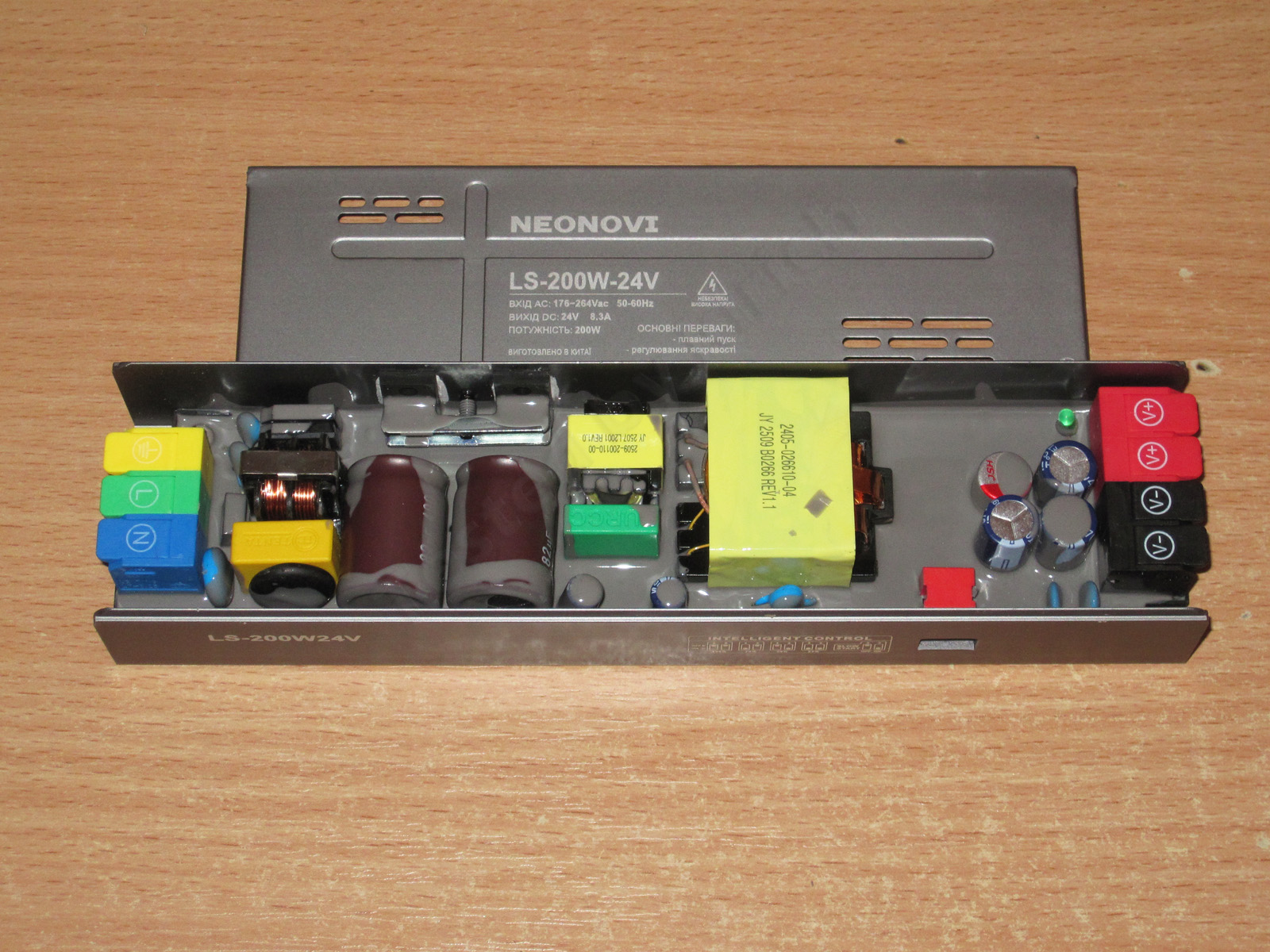
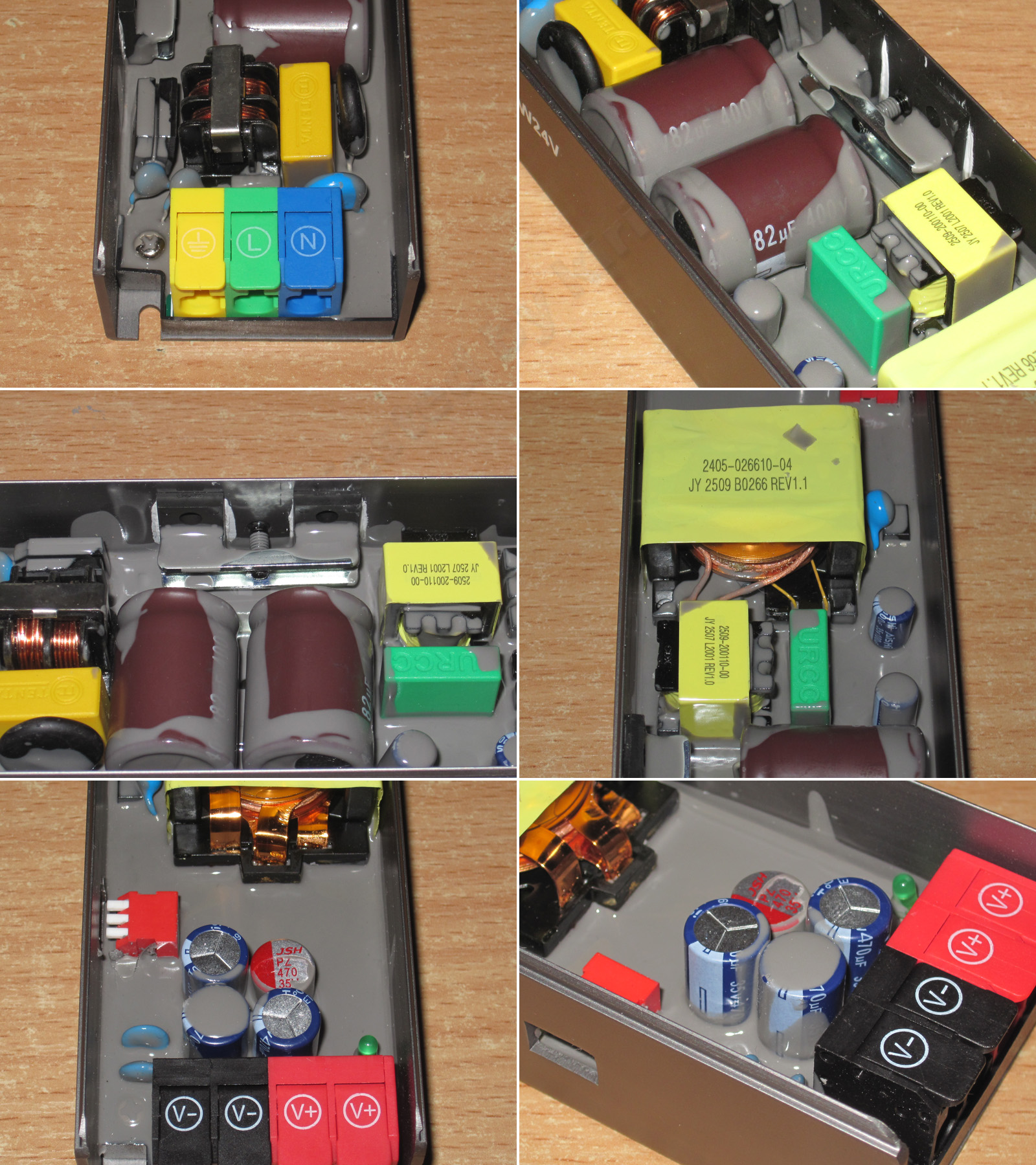
1. The same input filter as in the previous models.
2. Two 82 µF capacitors.
3. The transistors are clamped down with thermal paste.
4. The inductor-capacitor-transformer assembly. The Y capacitor is visible on the right; everything is neat and tidy.
5. I couldn't make out what rectifiers are used on the output. There's nothing visible there, but perhaps they'll show up in the thermal image later.
6. There are four output capacitors: three standard 470 µF, 35 V capacitors and one polymer capacitor, also 470 µF, 35 V.
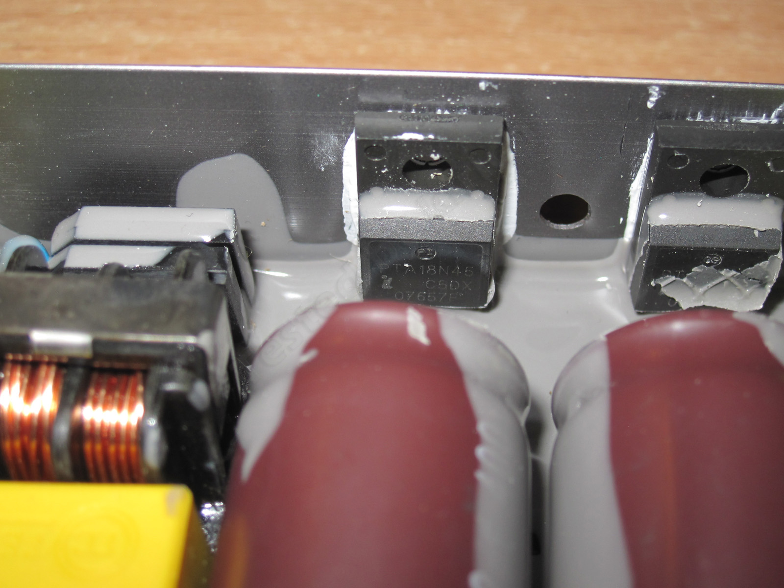
The transistors are 18N45, most likely rated for 18 A and 450 V, which is more than enough for this power level.
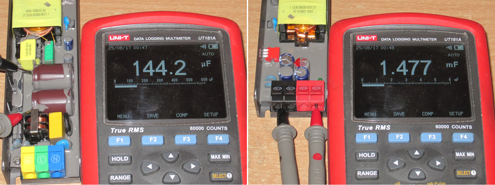
The input filter's total capacitance is 144 µF. That's perfectly adequate for this power level, especially given that this power supply is designed for the “narrow” 176–264 V range only.
The output capacitance is about 1500 µF. Given the polymer capacitor and the power supply's topology, that's probably fine too, but I'd have used two polymer capacitors and two standard ones instead.
Since this power supply is clearly more powerful than 150 W, I used a higher-power load as well.
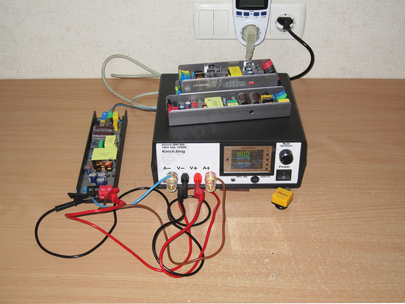
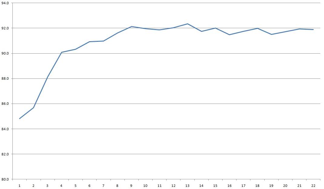
Testing showed that at 11 A the load starts reducing the output voltage, and at around 11.4–11.5 A it shuts down.
Efficiency is about 92%. What can I say? LLC topology is clearly more efficient than a conventional flyback. Interestingly, there's no characteristic “hump” like on the previous 300 and 400 W models; efficiency stays at 92% practically all the way up to the maximum current.
The graph was recorded at currents from 0.5 to 11 A in 0.5 A increments.
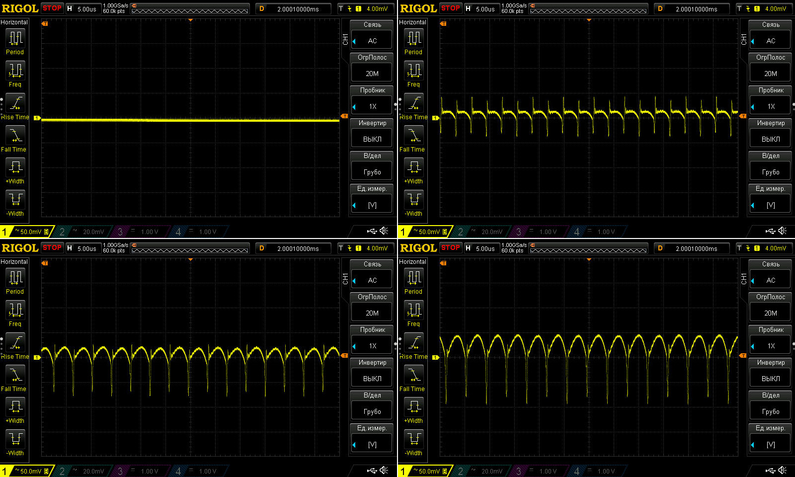
Ripple was measured with no load and at 3, 6 and 9 A. The maximum rated current is 8.3 A.
The results are excellent: even at 9 A, the total ripple is only about 150 mV, with the main component around 50 mV.
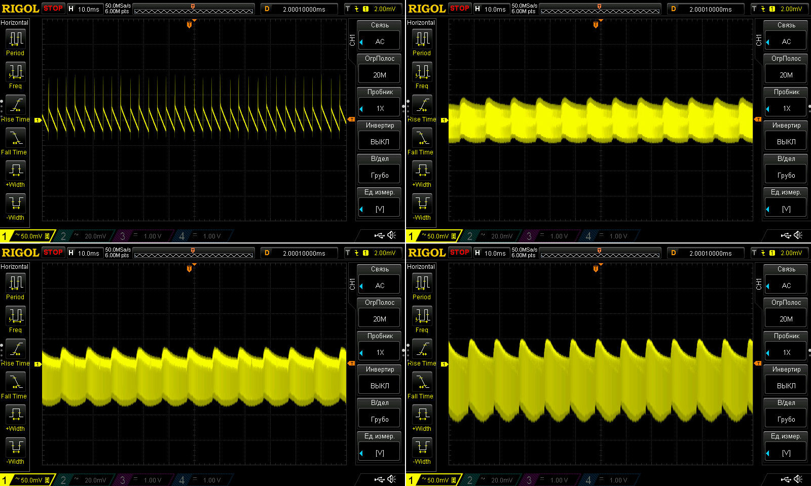
Some bumps appear at 100 Hz, but since the total ripple remains at 150 mV, I don't consider this a problem—just a characteristic of the design. And given that these power supplies were originally made for lighting, it's actually excellent. Overall, no complaints here.
Load test, plus an assessment of how the output voltage changes with temperature and heating.
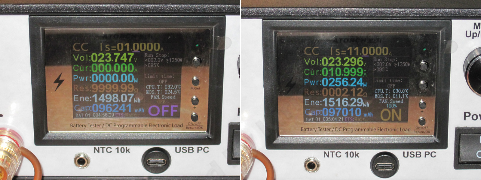
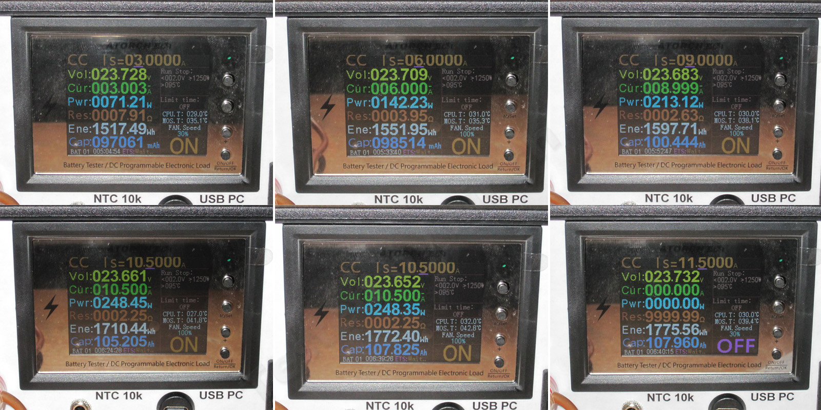
No load: 23.747 V
1. With the power supply cold and the current at 3 A, the voltage dropped to 23.728 V.
2. With the power supply warm and the current at 6 A, the voltage dropped to 23.709 V.
3. Once it had warmed up noticeably, at 9 A the voltage dropped further, to 23.683 V.
4. Then I decided to raise the current a little more, up to 10.5 A, close to the protection trip threshold.
5. I ran it like that for another 15 minutes; the voltage was 23.652 V.
6. I removed the load, and the voltage rose to 23.732 V, very close to the original 23.747 V. So the voltage dependence is almost nonexistent, while the dependence on load current is quite small, at around 80 mV.
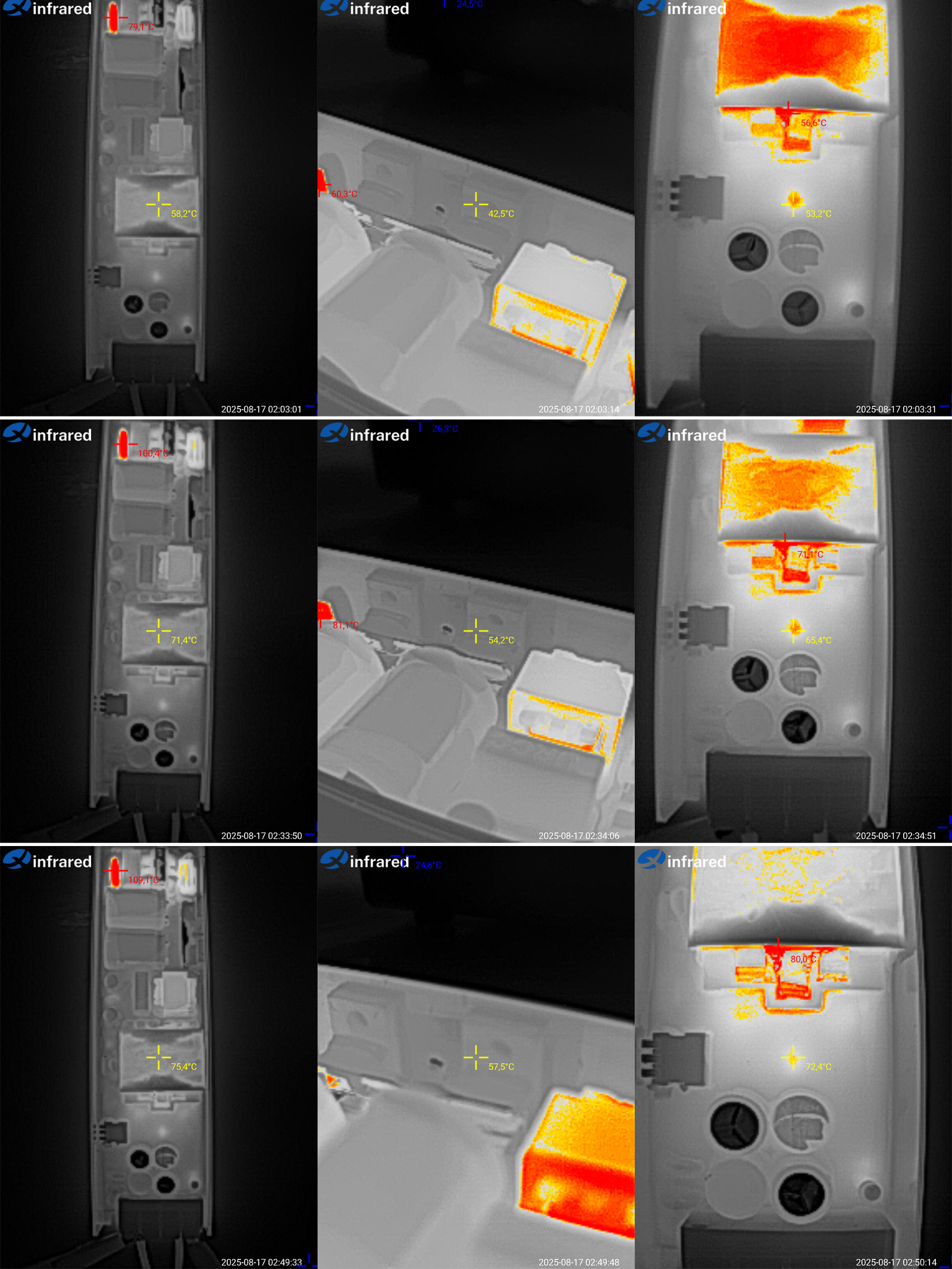
And here are the temperatures at 6, 9, and 10.5 A.
Since the results at 6 and 9 A are not interesting at all, I'll comment on how it behaves at 10.5 A, which is about 125% of the maximum rated load.
The transformer reached 75.4°C, the transistors 57.5°C. I couldn't find the rectifier, but based on the topology of the 300 and 400 W models, I assume the synchronous rectifier controller is what gets warm. Not by much, though—just 72°C.
Overall, the results here are excellent too. The power supply works great at 125% load, with no overheating. If you push it further, the protection will simply kick in. Reliability, baby.
The hottest components on the board were probably the input bridge rectifiers. There are two of them connected in parallel, and they reached 90°C at 125% load.
The inductor reached 75°C, and the transformer winding 84°C. All good.

And the fourth unit under test, the LS-400W-24V - link.
There is also an intermediate version, 300 W, 24 V - link, but I think its results will be somewhere between the 200 and 400 W models, especially since the 300 W, 12 V model performed very well.
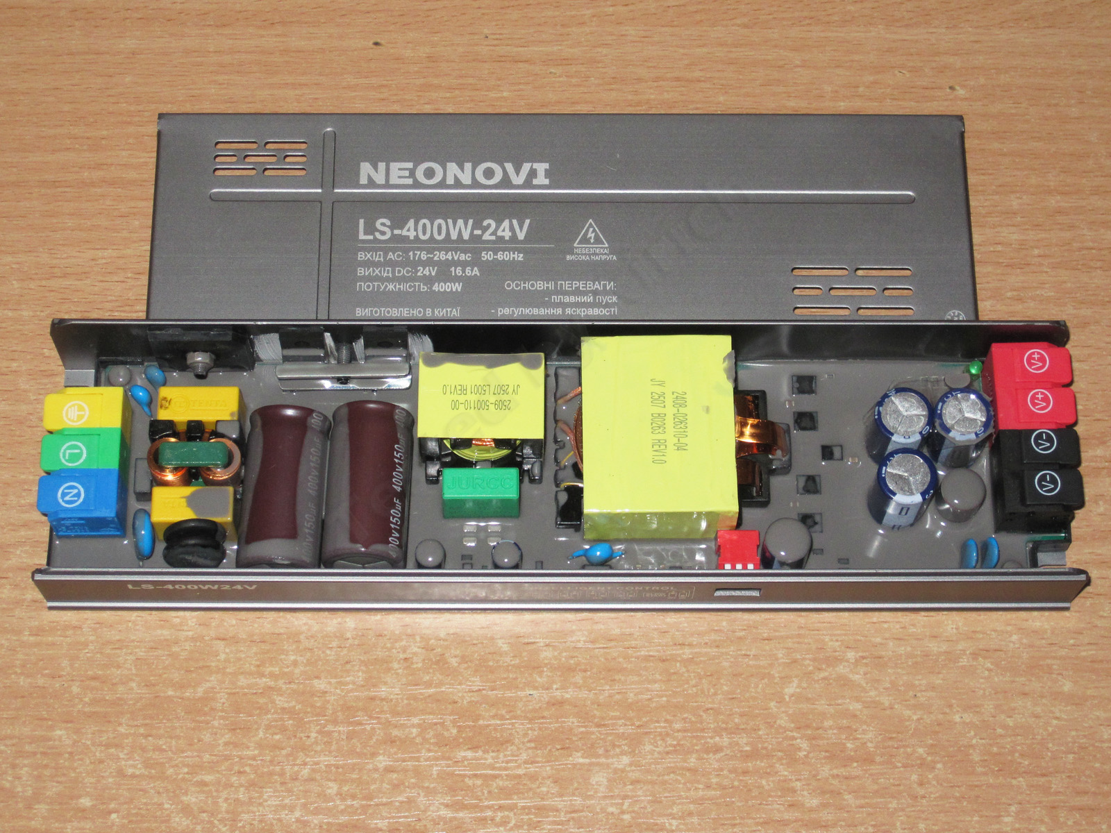
As you can see, the internals are essentially identical to the 400 W, 12 V model. The only differences are in some components that depend on the output voltage, such as the capacitance and voltage rating of the output capacitors. Here they are rated at 1500 µF, 35 V, plus one 470 µF, 35 V polymer capacitor.
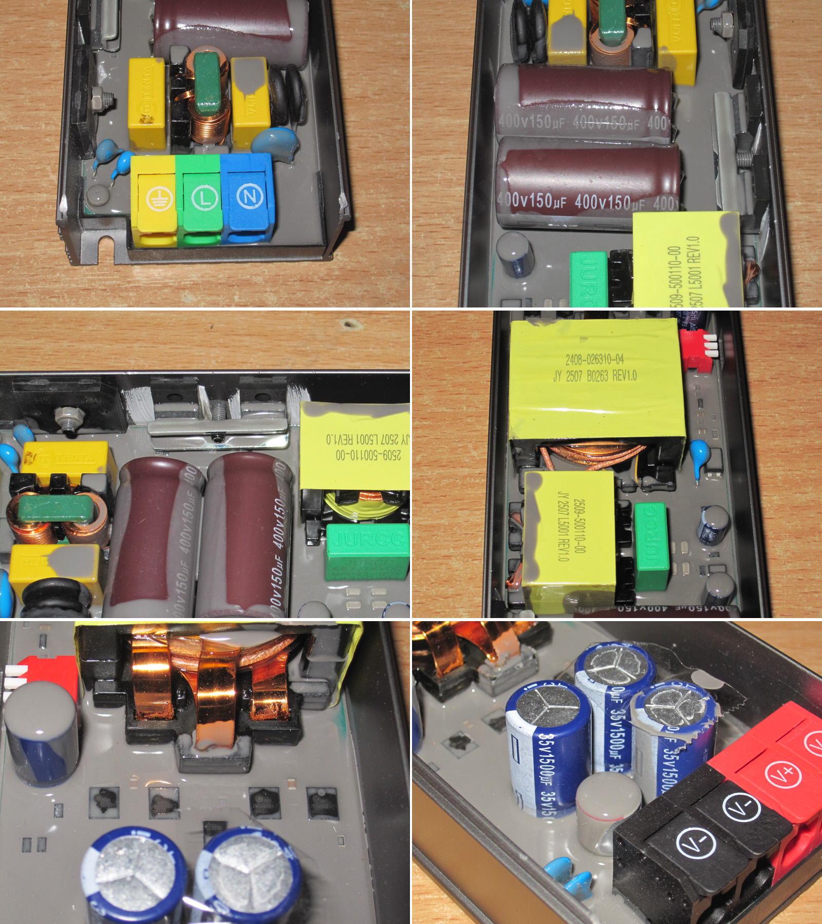
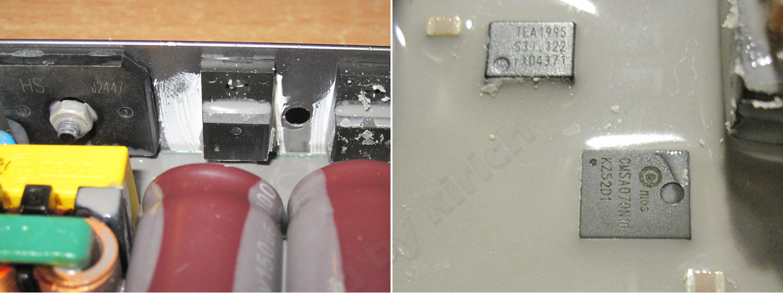
The transistors are the same as in the 200 W model, 18N45, but the output rectifier uses SMSA070N10, most likely 7 mΩ, 100 V.
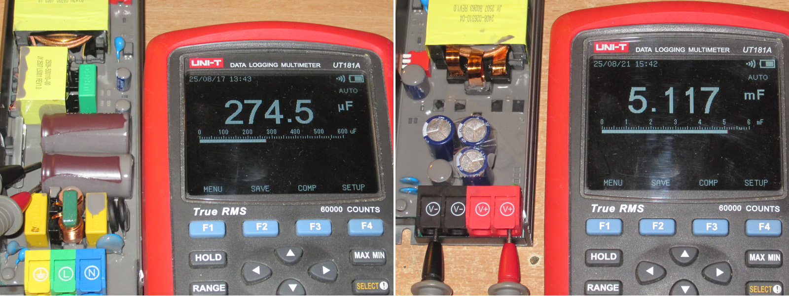
The input filter capacitance is about 275 µF, which seems a little low to me for a 400 W power supply. I would have gone with a bit more.
The output capacitance is about 5100 µF. Given the topology and the polymer capacitor, that may be fine, though.
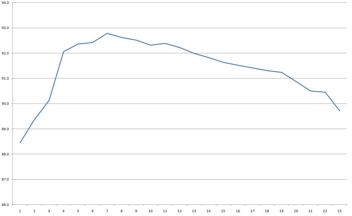
Efficiency was measured from 1 to 23 A in 1 A increments. Note that at 23 A, the output voltage started to drop, and increasing the current further triggered protection. In my opinion, the protection threshold isn't set quite right, although it's better than on the 12 V model. I'd still recommend lowering it to at least 20 A.
Efficiency is around 92–92.5%, but it has the same “hump” as the 300 and 400 W, 12 V models.
Incidentally, all else being equal, 24 V models will always be slightly more efficient (about 1%) than their 12 V counterparts.
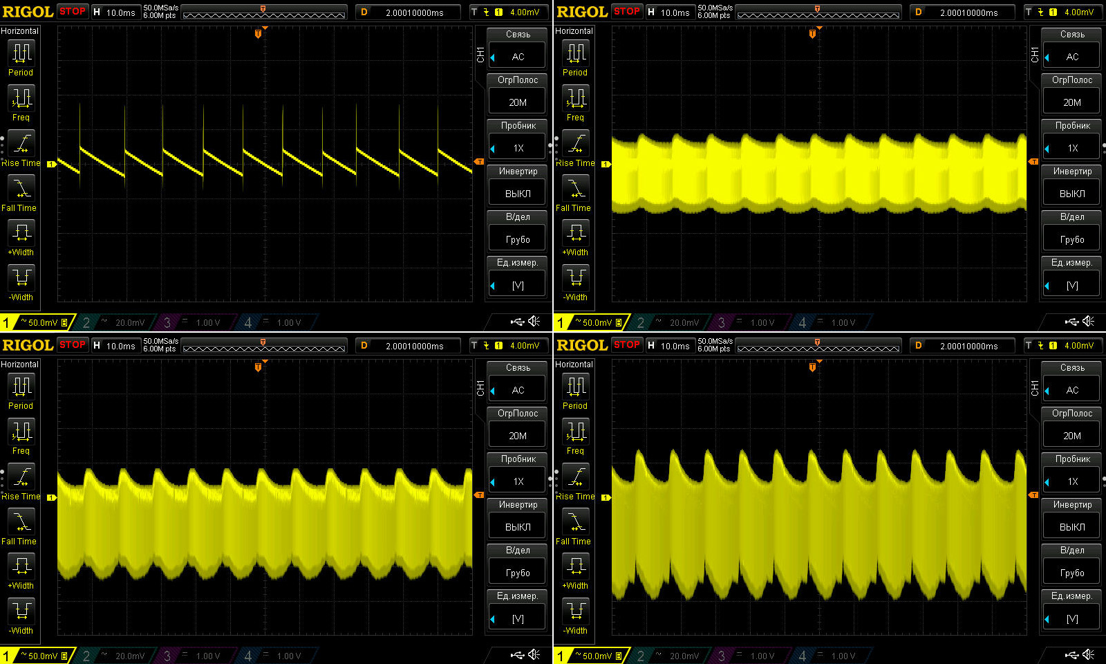
Ripple was measured with no load and at 6, 12, and 17 A. The maximum rated current is 16.6 A.
Nothing to complain about here. At 17 A, peak-to-peak ripple was about 180–200 mV. That's perfectly normal for a 24 V power supply—in fact, it's quite good.
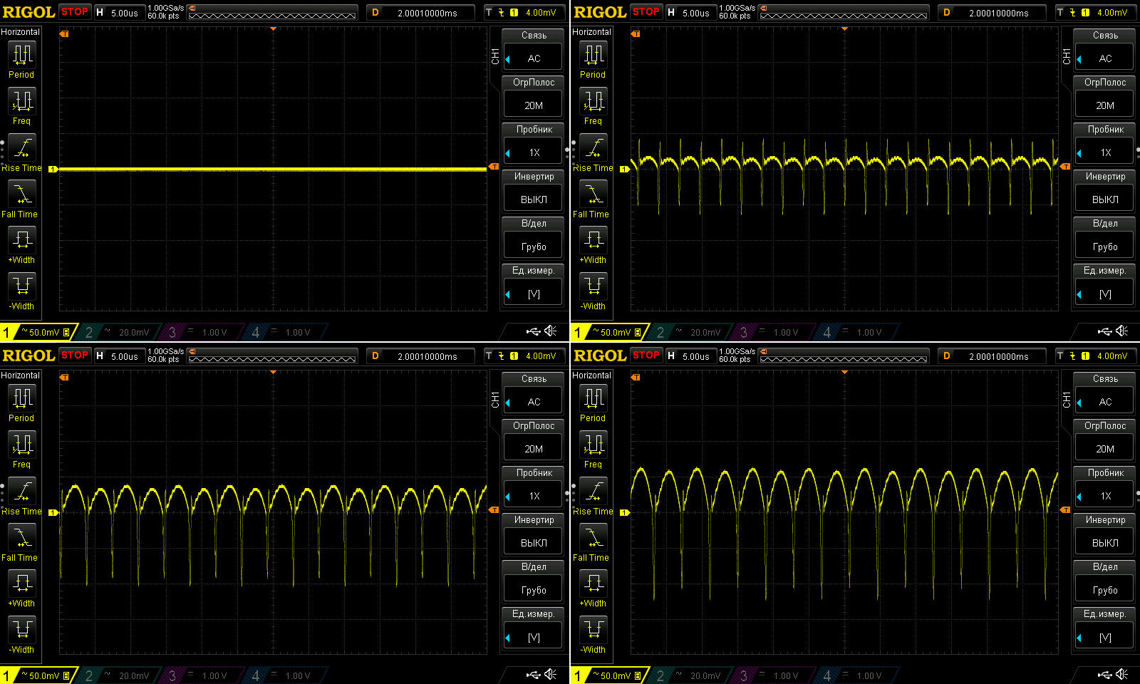
Some humps show up at 100 Hz, unfortunately, due to the relatively low input filter capacitance. Still, the peak-to-peak ripple remains the same, and the humps themselves are only 50 mV, so they look scary on the oscilloscope trace but aren't actually dangerous. Plus, as usual, I recommend leaving about 20% headroom on the load: temperatures and ripple will be lower, and service life longer.
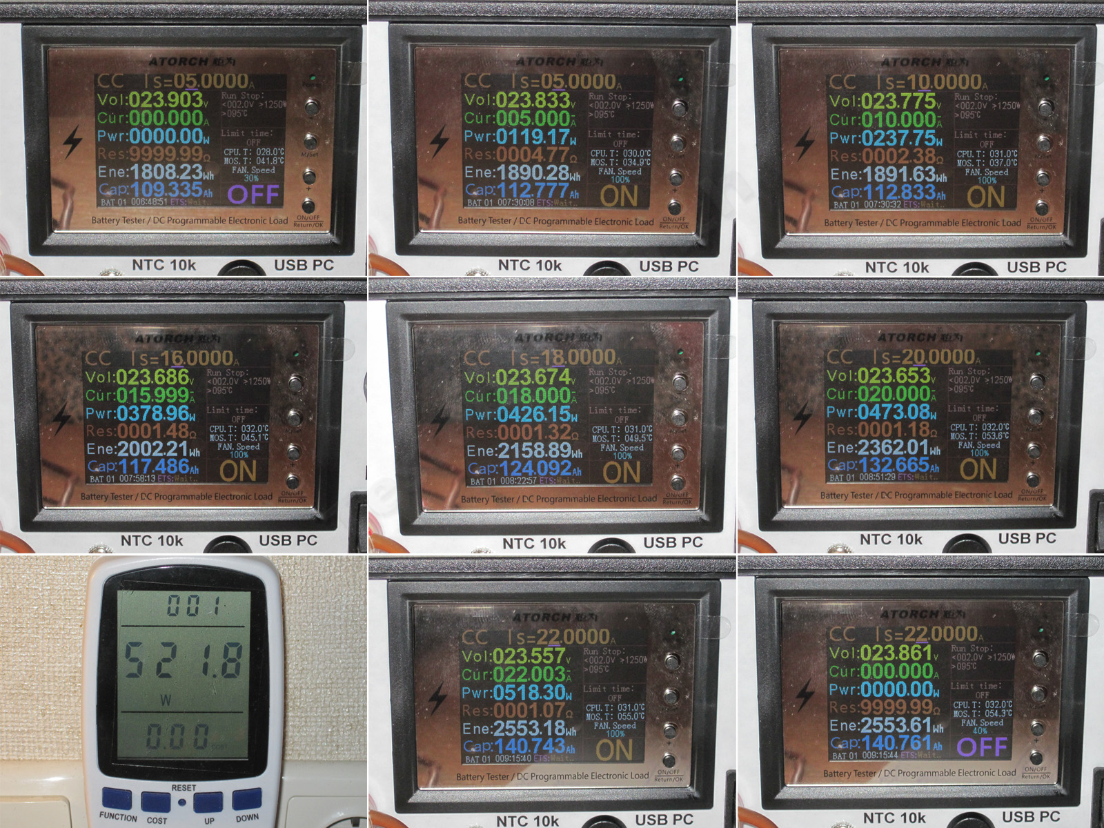
So, how about temperature and stability?
1. No load: 23.903 V
2. Cold power supply, 5 A load: 23.833 V
3. Warm power supply, 10 A: 23.775 V.
4. Fully warmed up, 16 A, close to maximum: 23.686 V
5. Hot power supply, 18 A, 426 W: 23.674 V.
6. 20 A, almost 120% of the maximum rated load: 23.653 V.
7. Input power is now over half a kilowatt.
8. Just out of curiosity, I briefly raised the load current to 22 A, but the power supply took it in stride. The voltage dropped noticeably to 23.557 V.
9. Removing the load, we get 23.861 V, compared with the initial 23.903 V. It dropped 40 mV as it warmed up, and about 250 mV under load (at 20 A).
The results are quite satisfactory, except that I’d have shut it down at 20 A.
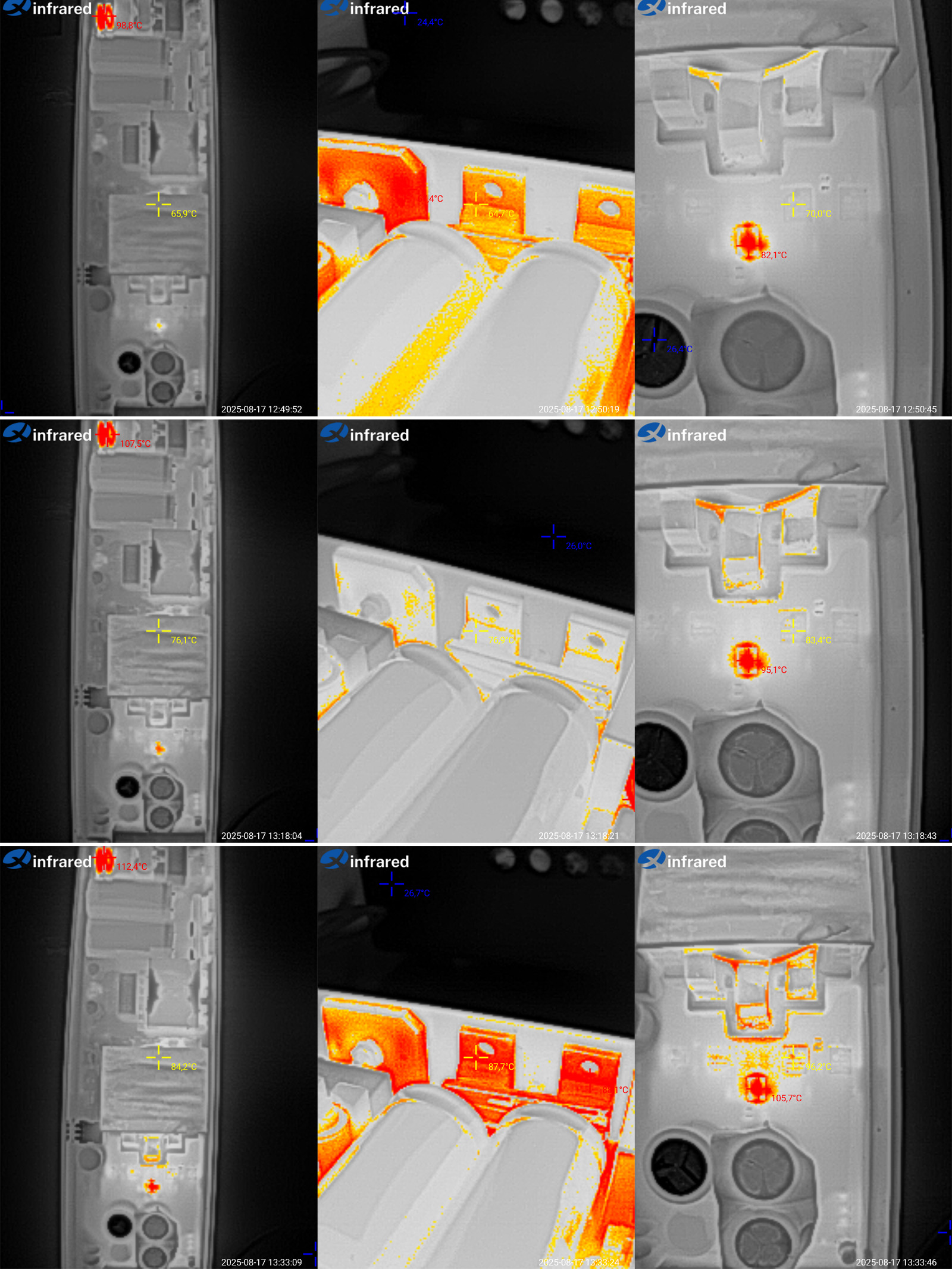
Since the test at 22 A was brief, here are the results at 16, 18, and 20 A. The last test, incidentally, ran for about 30 minutes, so I’ll comment on that one.
The transformer reached 84 degrees, the transistors 88 degrees, the rectifier’s output transistors 96 degrees, and the synchronous rectifier controller 105 degrees.
I’d call that moderate, but bear in mind that the current was 20 A, while the rated maximum is 16.6 A. At 16 A, everything is absolutely fine, which is exactly why I recommend that the manufacturer lower the overcurrent protection threshold to 20 A.
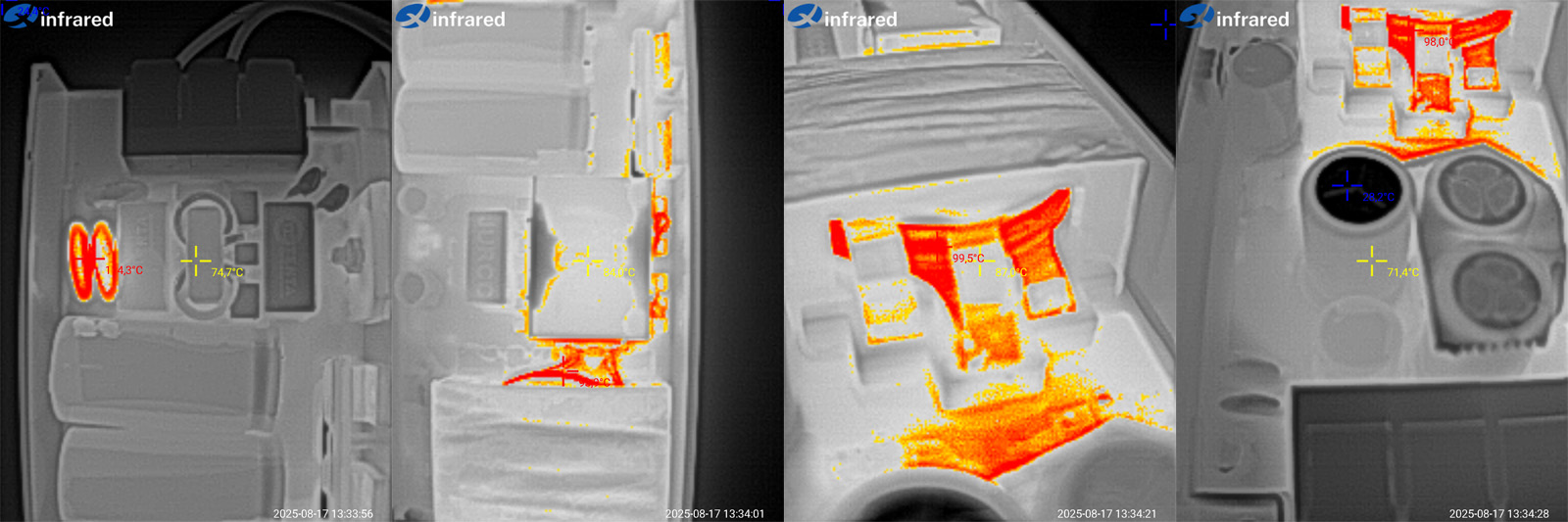
Temperatures of the other components at 20 A.
The input bridge rectifier was at about 88 degrees, the same as the transistors; the thermistors were at 114 degrees, which is perfectly normal for them; the inductor was at 84 degrees, also fine; the transformer winding was around 100 degrees, a bit high but tolerable; and the output capacitors were at 71 degrees, which is perfectly fine.
Conclusions.
60 W — excellent in every respect, apart from slightly odd ripple.
100 W — same story as the 60 W model.
200 W — no complaints at all: build quality, components, ripple, and temperatures are all excellent. Recommended.
400 W — I have two minor quibbles: I’d increase the input capacitor capacity a little and lower the overcurrent protection threshold.
Overall, I can confidently recommend the 60, 100, and 200 W models as excellent, and the 400 W model as very good, with one caveat: don’t overload it, at least until the manufacturer adjusts the overcurrent protection threshold.
That’s all for today. I hope this was useful. As always, I’d be glad to hear your comments, and thanks again to Vitaly.
227.87₴
This model is included in the summary table: Comparison of power supplies: ripple, efficiency, and temperature rise
The figures from this review are in the measurement database: Power supplies
Calculate manuallyAll calculators
Discounted products
You may be interested in



Discounted products
Support the project
All the content on the site and the advice are free, but we’d be grateful for your support of the project and the channel!
Discuss on the forumHave a question or some experience to share? Discuss the article with the author and readers: the forum is a convenient place to share schematics and photos.
Go to the forumOnly registered readers can comment. It takes a minute to sign up, and you can log in with the same account you use on the forum.
Log inRegister