
Ten budget 12 V power supplies, 1–8 A, in plastic enclosures
Strictly speaking, it would be more accurate to say 6+4 power supplies rather than 10: six arrived as samples for preliminary testing, and the other four came later, after some revisions, and are essentially production models. But the point remains the same: today’s review covers ten 12 V power supplies of various power ratings.
A reminder: to keep up with new posts on the blog, I recommend following me on Instagram. I’ll post notifications about every new article there, and might also write about something interesting from time to time — link to my account
You can also subscribe to updates and new articles on the Telegram channel — https://t.me/KirichBlog
A package arrived with ten different power supplies. I’ll say right away that, in my opinion, a plastic enclosure is far from the best choice for a power supply. The problem is that heat dissipation is much worse in enclosures like these. Still, it’s the simplest way to make a complete, ready-to-use device.
You’ll probably say, “What about laptop power supplies and the like?” Yes, fair enough, but those are a very different story. First, the components and circuit design are more sophisticated, so efficiency is much higher. But the main difference is the layout: potting the board with sealant or compound removes the air, so heat is transferred to the plastic enclosure almost immediately (and sometimes literally right away). The plastic can also have fairly good thermal conductivity. In cheap, no-name Chinese models, the components first heat the air, which then warms the enclosure through natural convection. The result is a relatively warm enclosure and hot electronics. Laptop-style power supplies may feel as hot as a stove, but that’s because the components transfer heat efficiently, so their actual temperature isn’t as high.
Obviously, Chinese factories churning out the cheapest possible models aren’t going to bother with this: it’s complicated and expensive. So we get what we get.
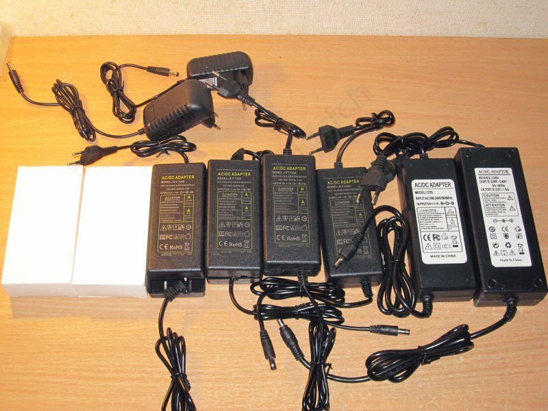
As I said, the power supplies are split into two groups: six and four. I’ll start with the six models sent as samples. Four of them look identical.
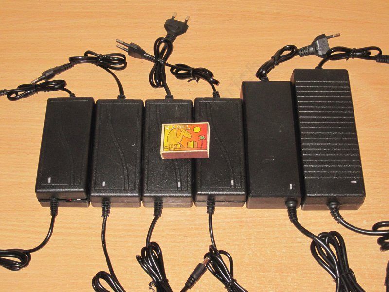
All the power supplies are rated for 12 V, with claimed output currents of 3, 4, 5, 6, 7, and 8 A, and are marked 1203–1208, respectively.

As usual, I’ll go in ascending order, starting with model 1203 and ending with 1208.
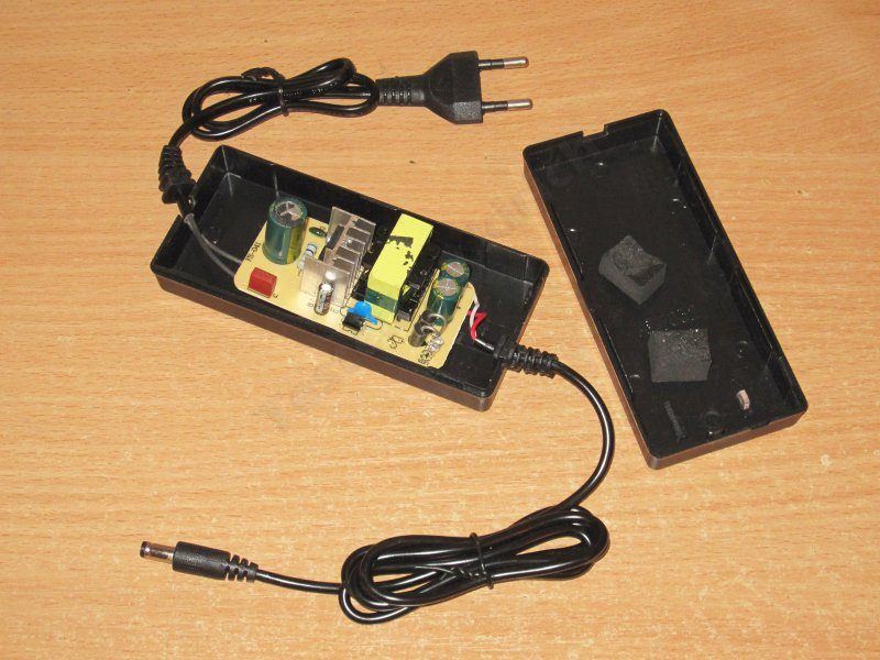
First up is the 12 V, 3 A power supply. Inside, it’s empty and sad.
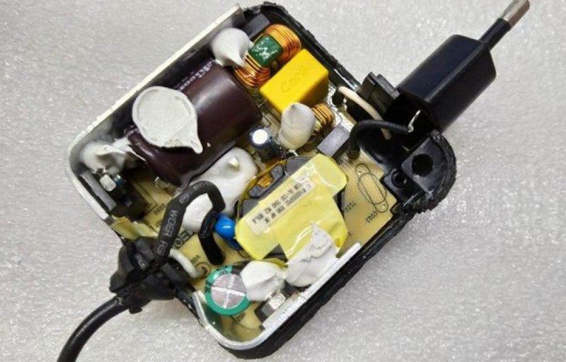
Here’s a Lenovo laptop power supply as an example. It’s rated at around 45 W, and you can see that the heatsinks are positioned to minimize the air gap. This costs nothing—or almost nothing—to do in production; you just have to think about it a little. The same goes for the transformer: you can transfer heat to the enclosure in the same way, either directly through a thermal pad or by adding a heat spreader. And I haven’t even mentioned designs where part of the heatsink sits directly in the plastic enclosure, as in some Mean Well models.
All these tests are making me increasingly keen to design my own budget power supply and then place an order with the same factory that makes the cheap ones.
I noticed something interesting during the initial inspection: the opening for the LED in the enclosure is designed to work either way, so it’s easy for the factory to put it on the left or the right.

There’s no input filter; the design is as simple as it gets. At least they didn’t forget the fuse.

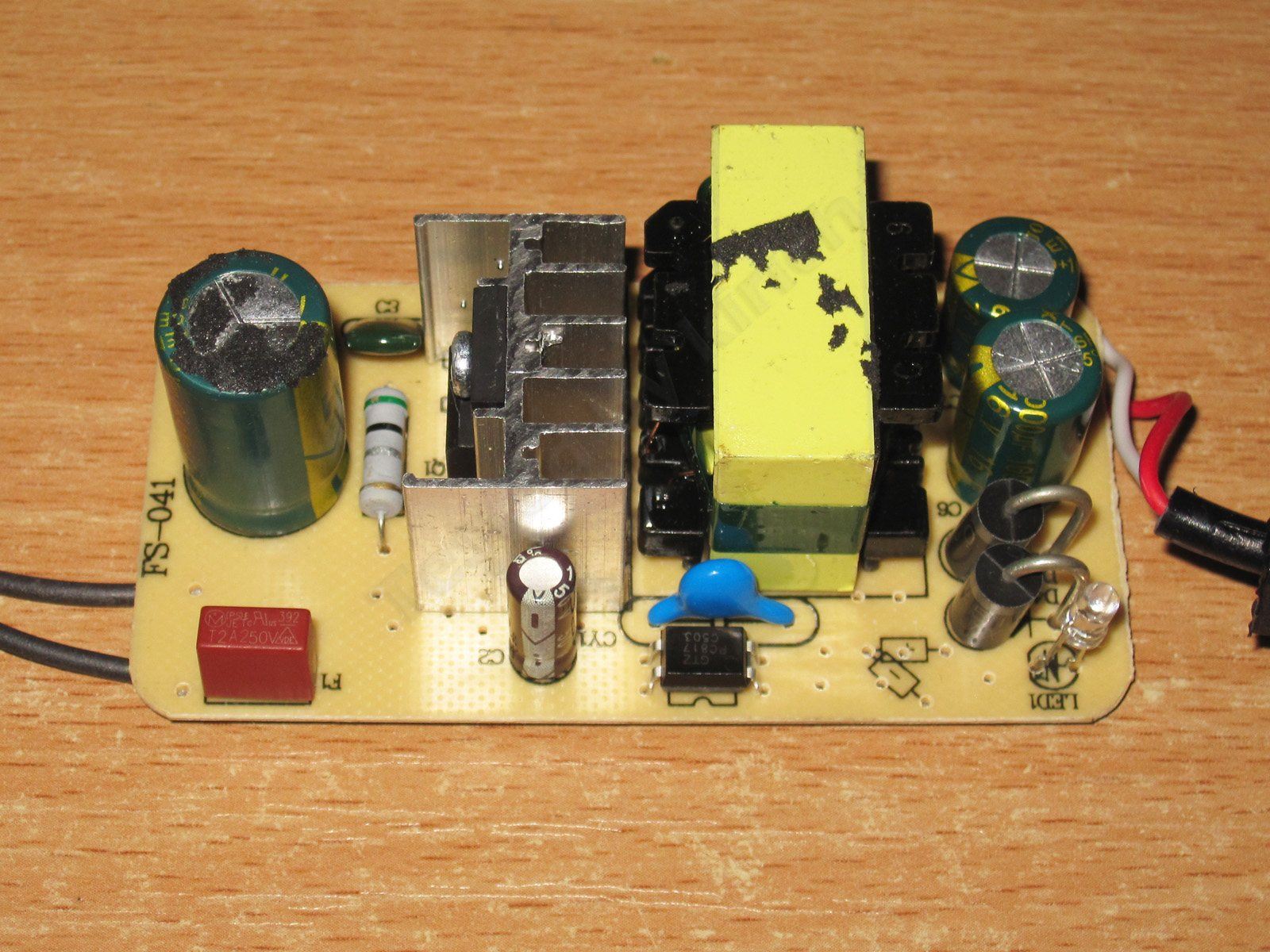
The input capacitor is marked 47 µF, the transistor is rated for 5 A, and there’s a Y capacitor. On the output, there are two diodes and two capacitors rated at 16 V: 680 + 1000 µF.
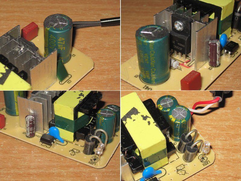
No complaints about electrical safety, or the circuit board, for that matter. The assembly is even reasonably neat, apart from the usual Chinese habit of soldering wires directly to the traces instead of through the holes.

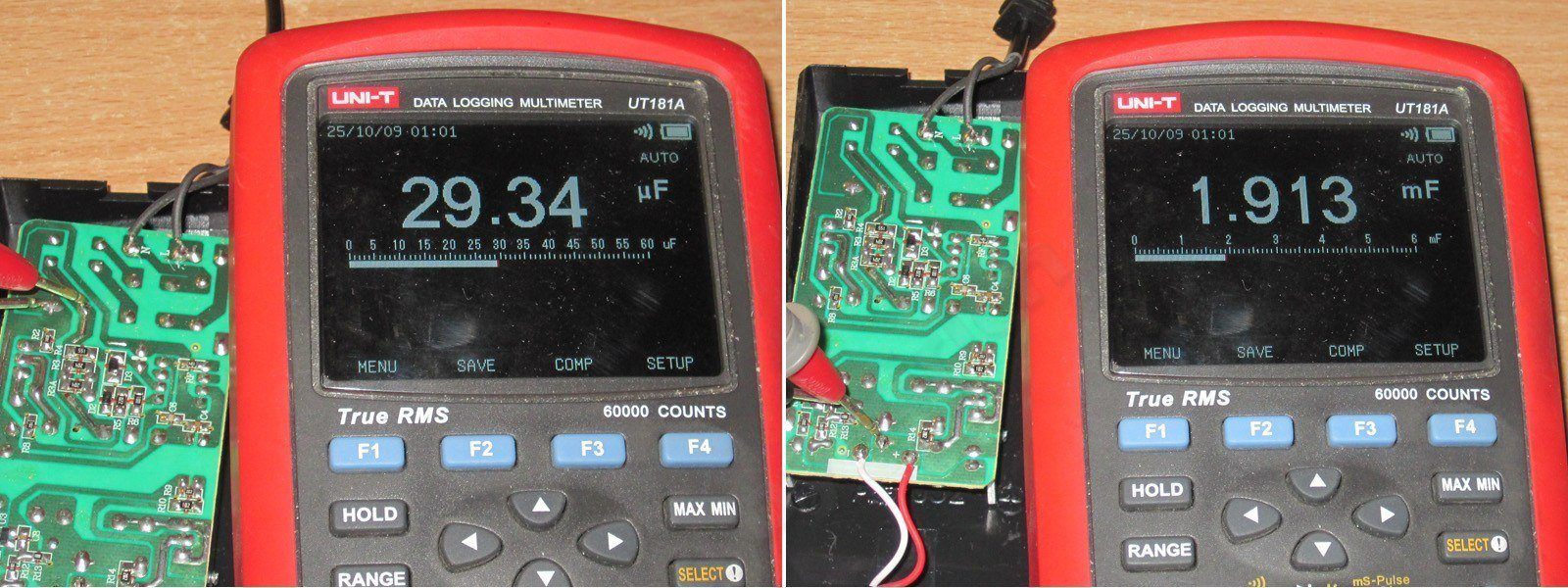
The input capacitor’s actual capacitance is 30 µF, and the output capacitors add up to 1650 µF. It’s clear that the input capacitor should have been marked 33, but they decided to make it look “nicer.” Still, 30 µF is enough for a 230 V mains supply and 36 W output power.

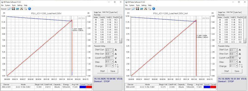
The overcurrent protection trips at a much higher current than it should: although the rated current is 3 A, it doesn’t kick in until 5.7 A, which is far too high. The trip current doesn’t depend on temperature.
The output voltage measured at the power supply terminals is 12.28 V with no load, and varies from 12.28 to 12.25 V over the 0.5–4 A range, which indicates good regulation. Everything else you see on the graph is due to the voltage drop across the thin output cable.
No-load power consumption is about 0.45 W.
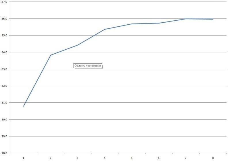
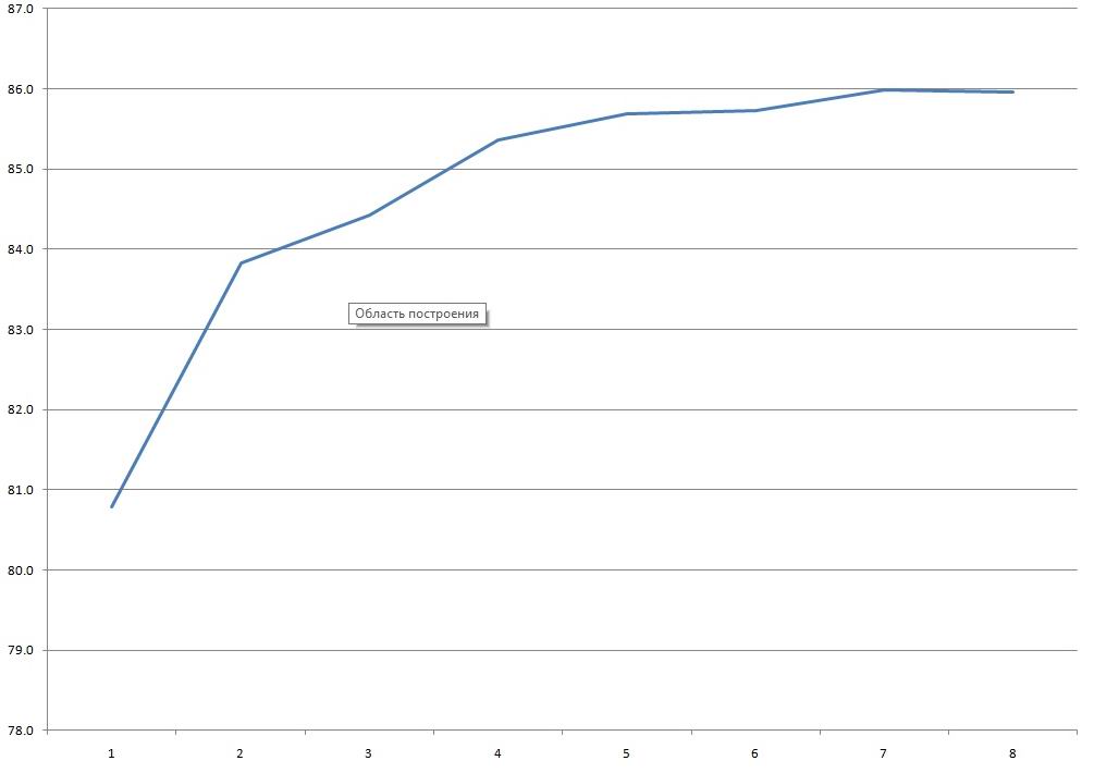
Efficiency is around 85%, which is fine for budget models. Efficiency was measured from 0.5 to 4 A in 0.5 A increments.
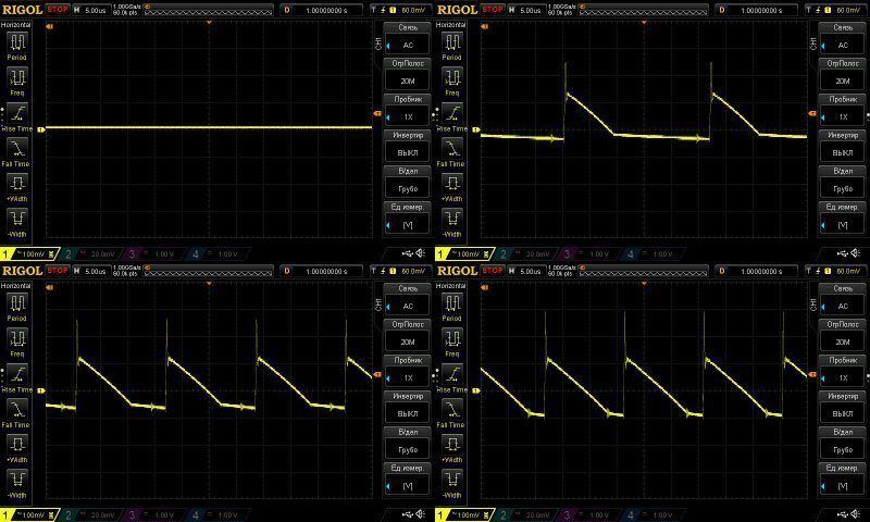
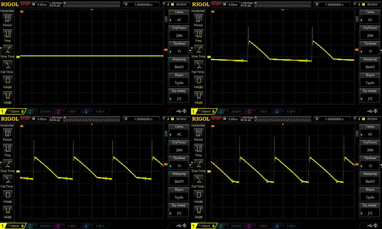
As usual, I measured high-frequency ripple with no load and at 33%, 66% and 100% load. At maximum current, the main ripple component is around 200 mV, which is quite acceptable for models like this.
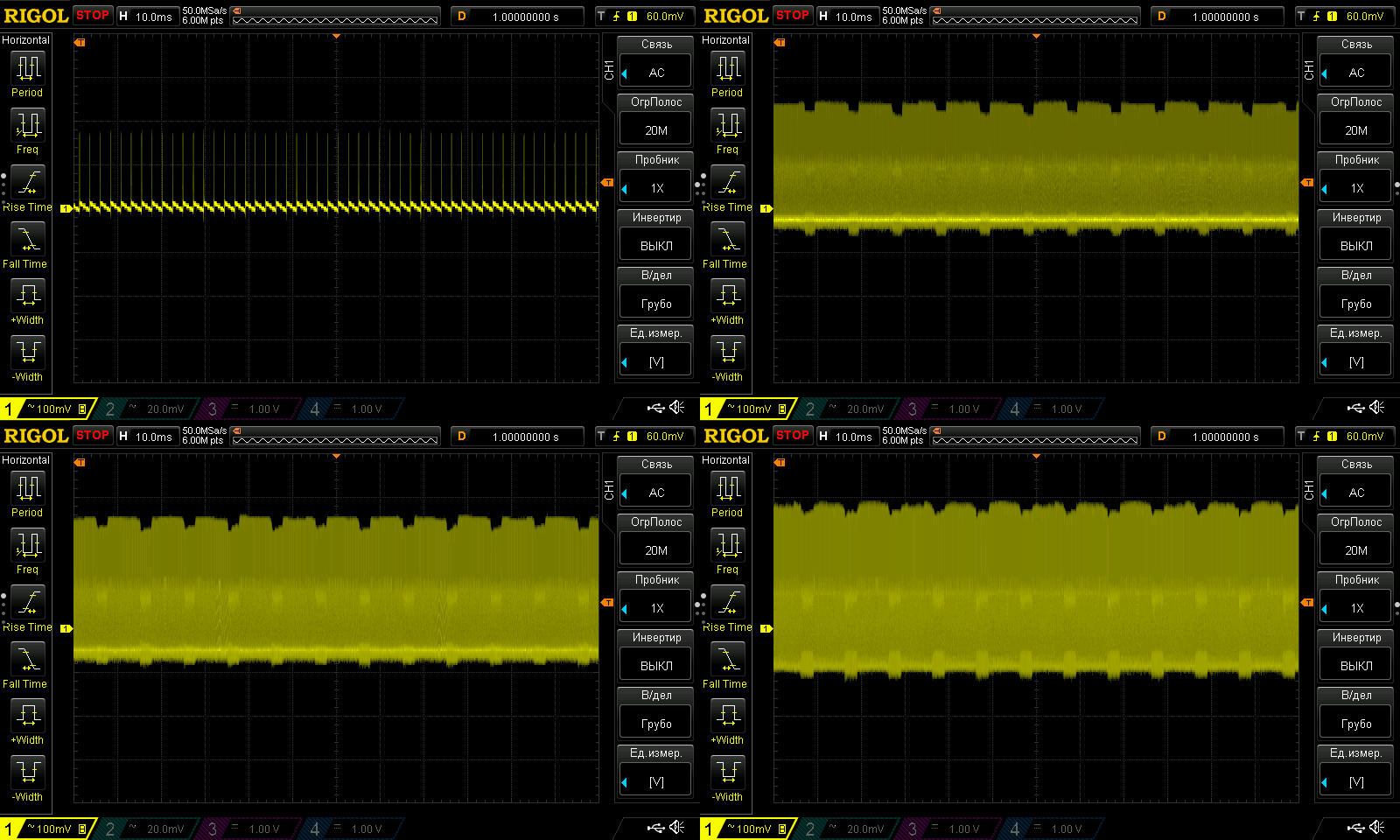
There are no issues with 100 Hz ripple either, so we can consider this test passed.

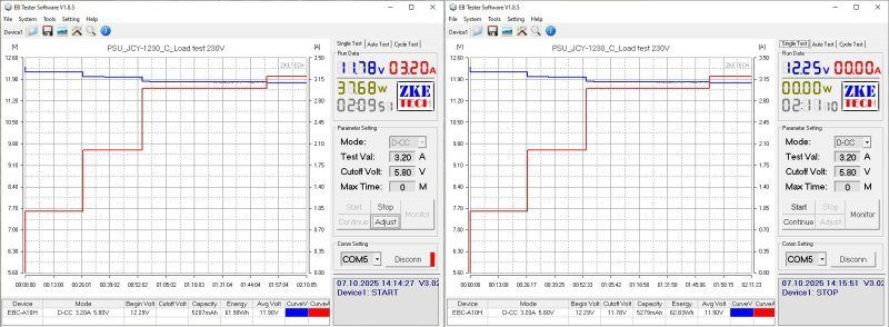
I tested it at 1, 2, 3 and 3.2 A; the last step was just out of curiosity. The output voltage has a slight negative temperature coefficient: when hot, the unit's output is 40 mV lower than when cold.
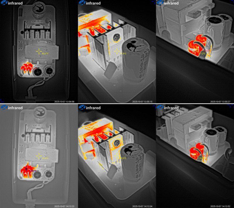
Temperature rise at load currents of 3 and 3.2 A. Here, I'd even say everything looks fine: the transistor is ideal, and the transformer does pretty well too. The output diodes get fairly hot, but if you keep the current below 2.5 A, it should work without problems. The one thing that definitely needs changing is the protection current setting.
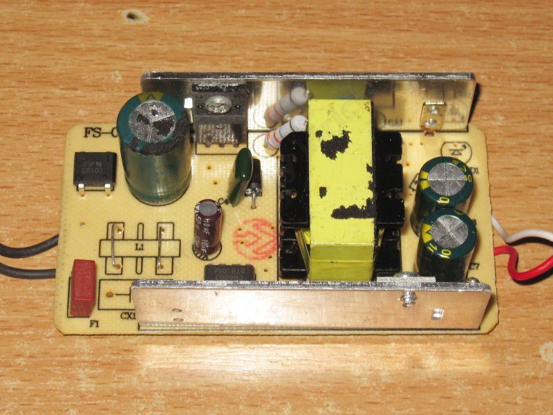
The 1204 is a 12 V, 4 A unit. Essentially, it's not much different: they added a heatsink to the output diode assembly and moved the transistor heatsink to the side.

There's no filter here either. I should say that the lack of a filter isn't always critical, but a thermistor would definitely help, since it limits the inrush current while the input capacitor charges. The larger the capacitor, the more important it is to have a thermistor.
The input has only a fuse. The capacitor is marked 47 µF, just like in the previous version. The transistor is rated for 7 A, and there's a Y capacitor. On the output, there's a 20 A diode assembly and a pair of 16 V, 1000 µF capacitors.
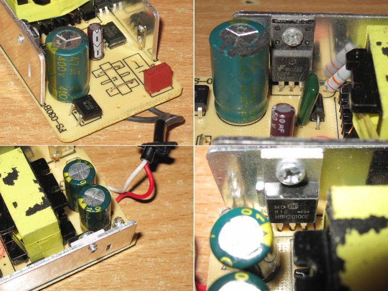
From an electrical safety standpoint, the board has two critical points: the heatsink mounting points. The upper heatsink is connected to the output because the diode assembly isn't insulated. The transistor is in an insulated package, but its heatsink is connected to the negative side of the high-voltage input.
The only way to fix this is to change the PCB routing and the location of the heatsink mounting contact.

The input capacitor is 30 µF, just like in the previous version. The output capacitors are fine: 1000 + 1000 µF.
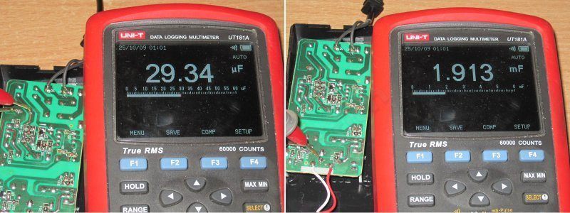
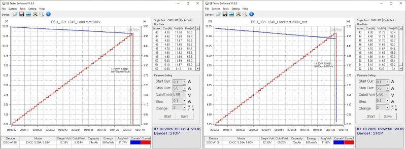
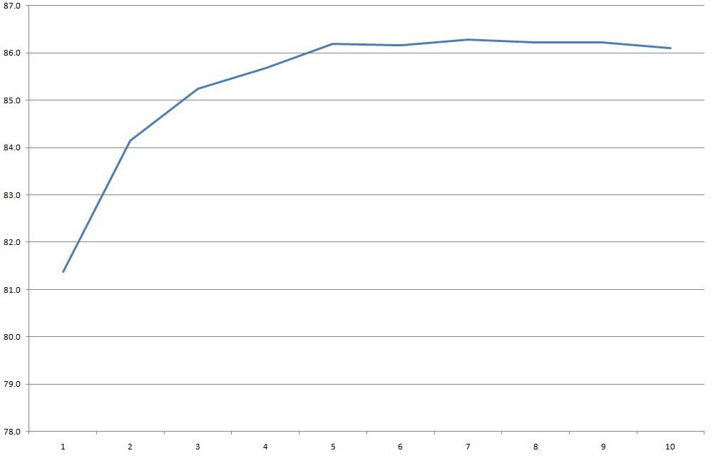
The protection trips at 5.2 A, which is quite acceptable. With no load, the output is 12.37 V, and the unit draws 0.45 W, just like the previous one.
As the load current increases from 0.5 to 5 A, the voltage at the board terminals drops from 12.37 to 12.33 V, which is excellent.
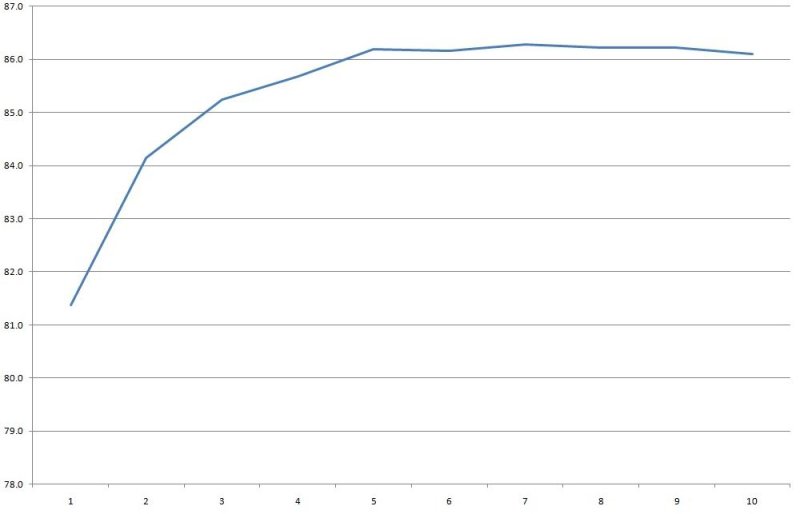
Efficiency is around 86%, measured from 0.5 to 5 A in 0.5 A increments.
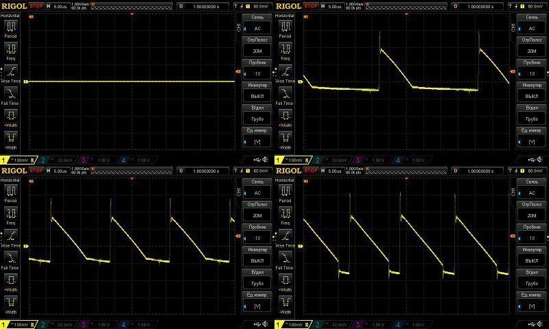
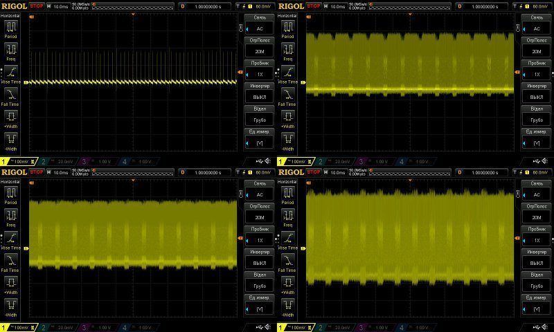
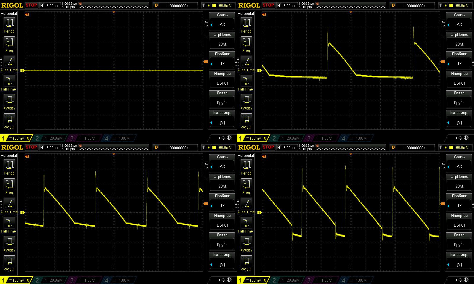
High-frequency ripple with no load and at currents of 1, 2 and 4 A.
This is worse than the previous unit: at 4 A, we get around 300–350 mV, not counting the spikes. It's not a complete disaster, but I'd like to see better results, and I wouldn't use it with sensitive loads.
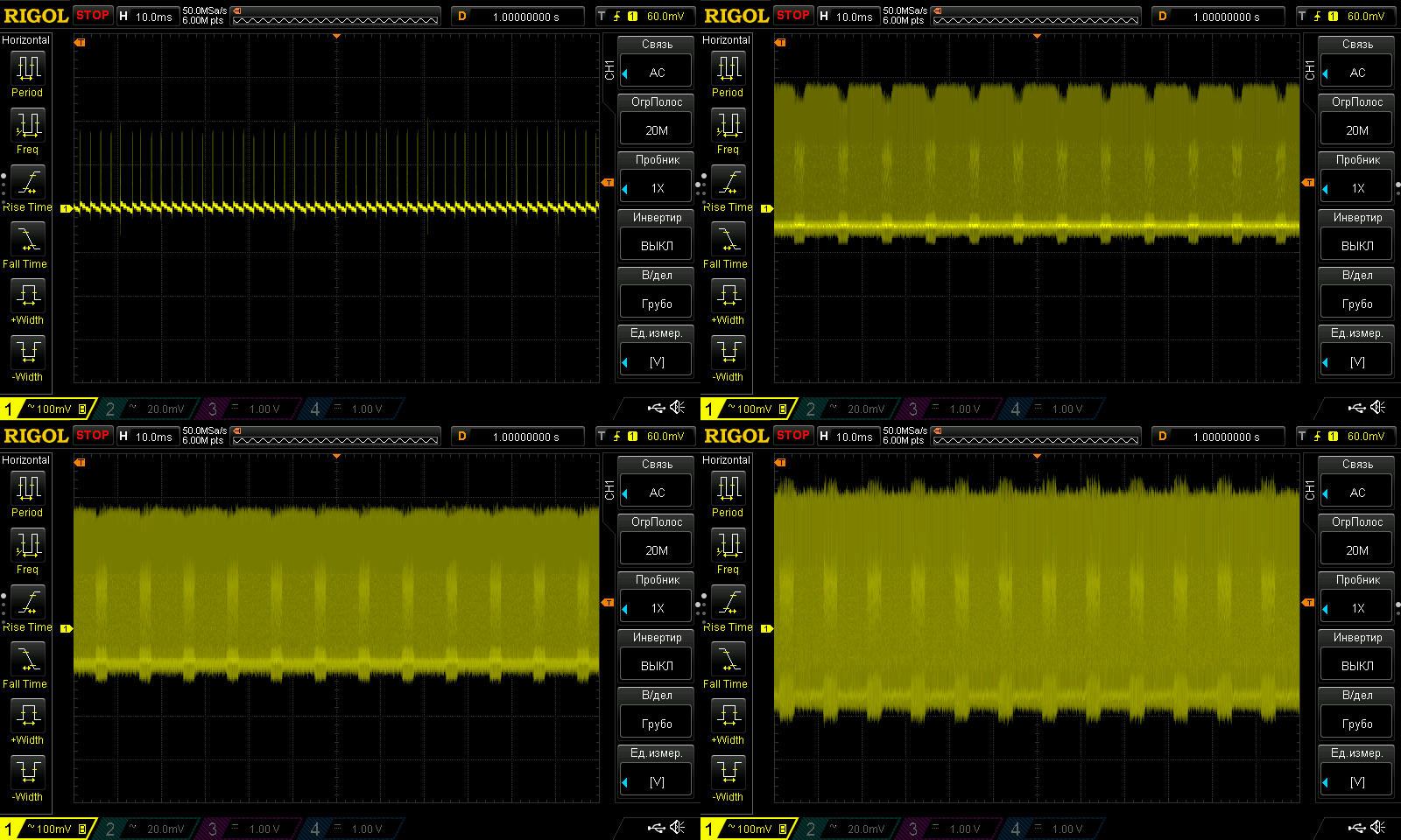
No complaints at 100 Hz.
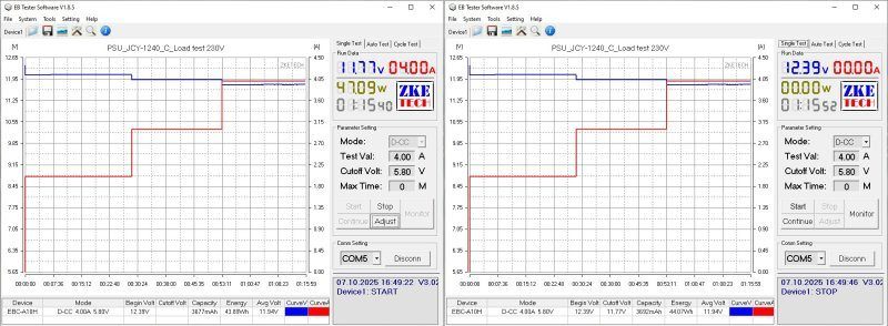
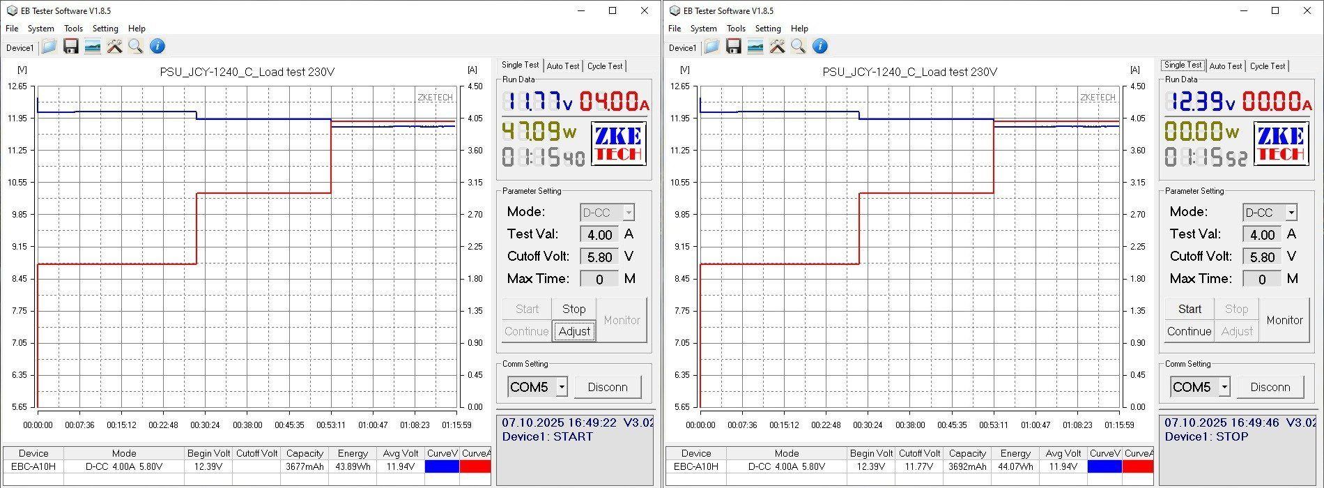
I checked the temperature rise at 2, 3 and 4 A. The output voltage is practically unaffected by temperature: it was 12.39 V and stayed at 12.39 V.
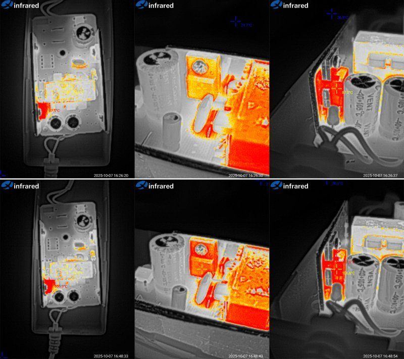
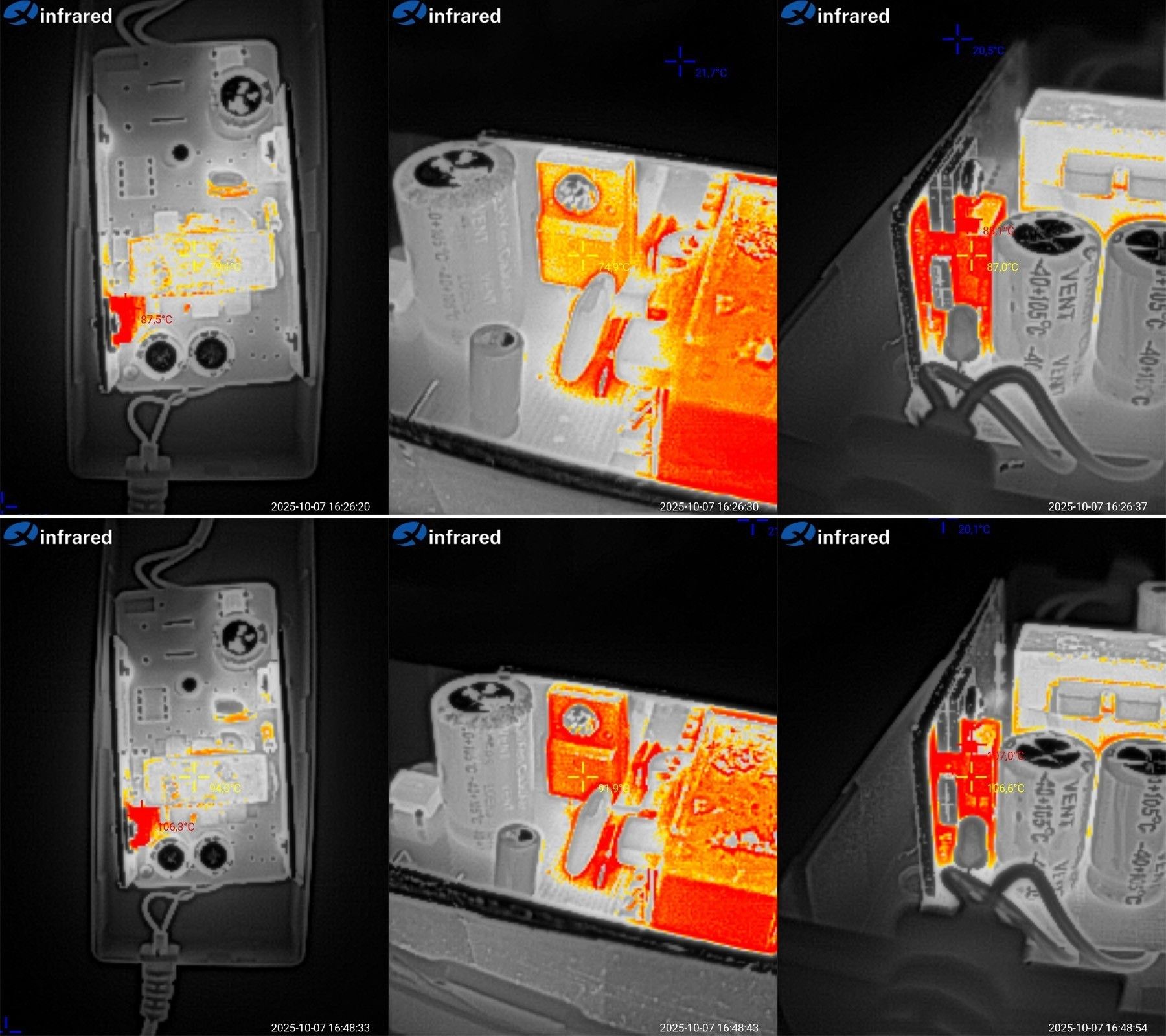
Temperatures at 3 and 4 A.
I have to say, things look more or less good here:
At 3 A, the transformer is at 79°C—excellent; the transistor is at 75°C, also good; and the diode assembly is at 87°C, which is fine.
At 4 A, the transformer is at 94°C, which is acceptable; the transistor is at 92°C, also no complaints; and the diode assembly is at 107°C. That's not too high, but there's not much headroom.
Personally, I wouldn't run it continuously above 3–3.5 A. At that load, it should last a good long time, although at room temperature it handles 4 A just fine.
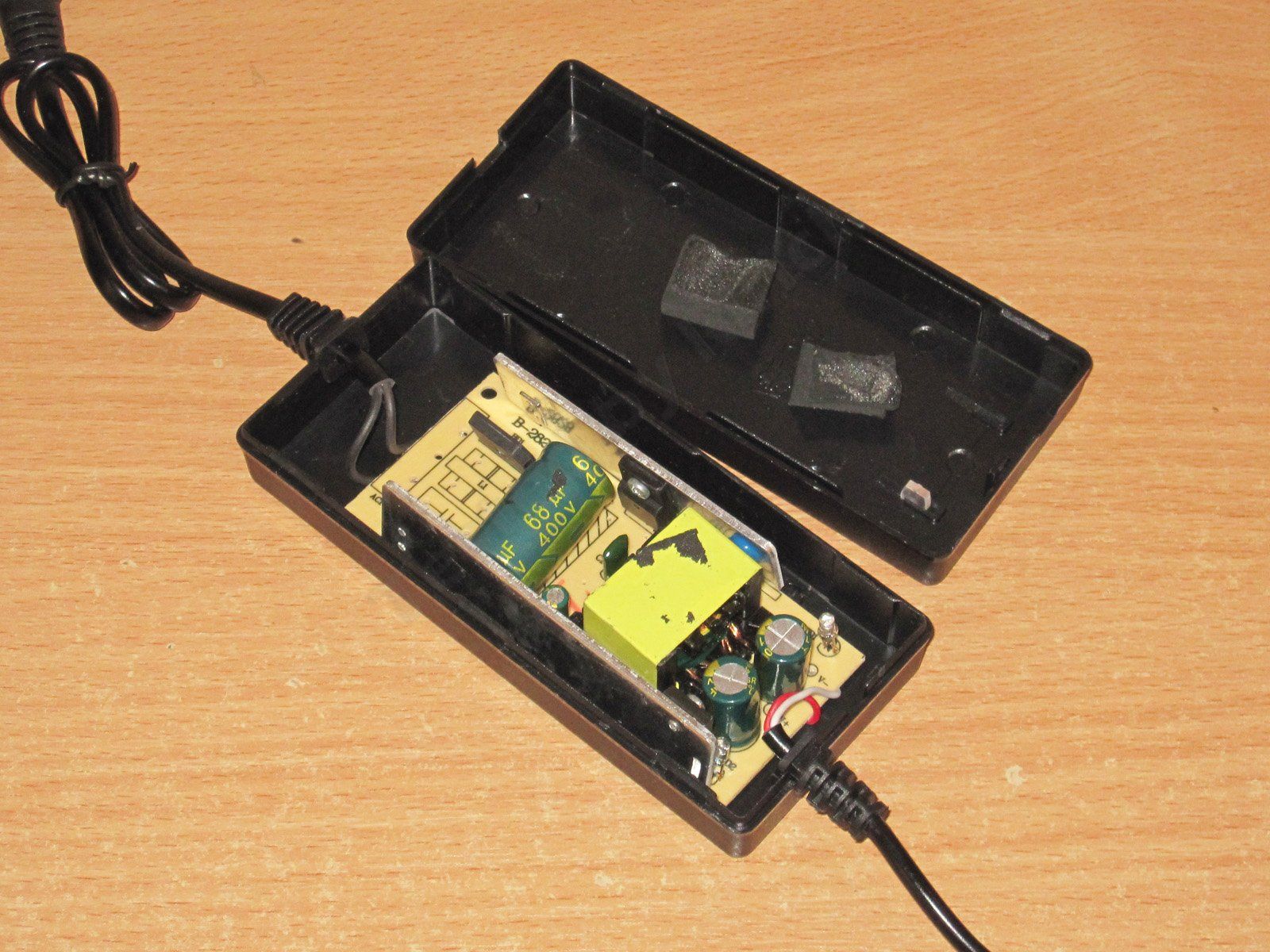
The third unit under test is the 1205 model, rated at 12 V, 5 A.
Essentially, this is a slightly modified version of the previous one.
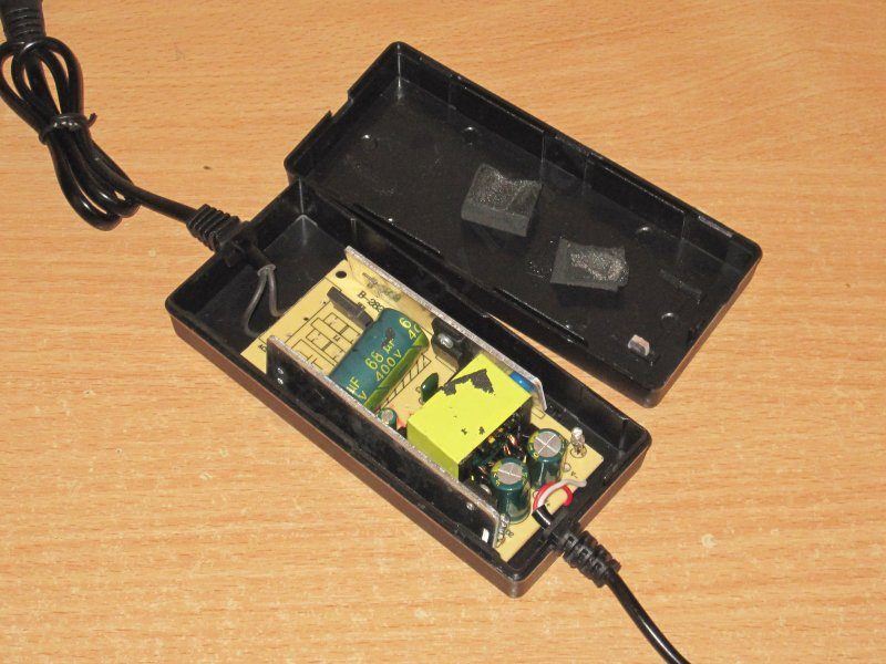
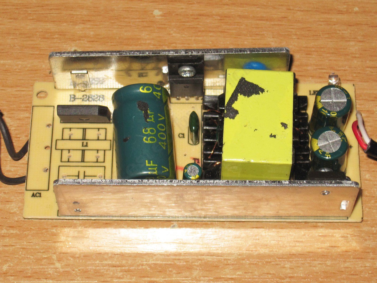
The visible changes are a larger bridge rectifier, a higher-capacitance capacitor, and slightly beefier heatsinks.
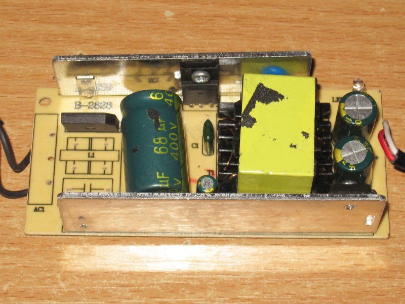
The input capacitor is marked 68 µF. The transistor is rated for the same 7 A as the one in the previous unit. There is a Y capacitor, hidden between the transformer and the heatsink. On the output, there are two 1000 µF, 16 V capacitors. The diode assembly marking is hard to read; I think it's 20 A.
One interesting thing: it has two LEDs, a main one and a backup :))))
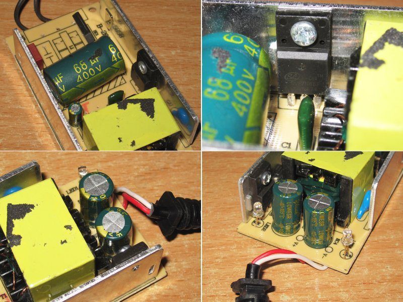
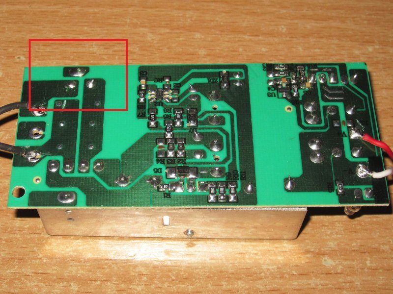
The board is pretty typical for this kind of power supply. As for safety concerns, the diode heatsink mounting point is close to a hot-side trace, but since the diode assembly is in an insulated package, it's not that critical.
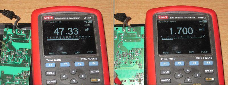
The input capacitor has an actual capacitance of 47 µF, exactly one step down in the E6 series. The output capacitors add up to 1700 µF, which is odd; usually there are no complaints about them.
The protection is set to about 5.5 A. Once the current limit is exceeded, the output voltage starts to drop rather than shutting off completely.
When the unit is warmed up, it trips a little earlier.
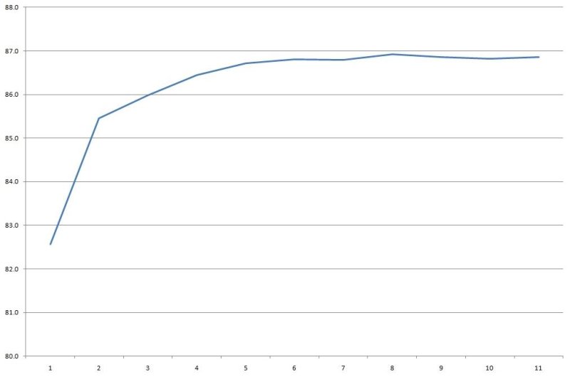
The no-load voltage is 12.22 V, and power consumption is 0.35 W. With a load current of 0.55 A, the voltage at the board terminals drops from 12.22 to 12.04 V, which is acceptable.

Efficiency is almost 87%, which is pretty good for a budget power supply. Efficiency was measured from 0.5 to 5.4 A in 0.5 A increments.
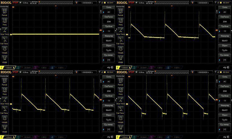
Ripple at no load and at currents of 1.5, 3, and 5 A.
The high-frequency ripple is acceptable, around 250–300 mV at maximum current, but there are some very large spikes. They aren't too critical for the load, but they do make life hard for the capacitors.
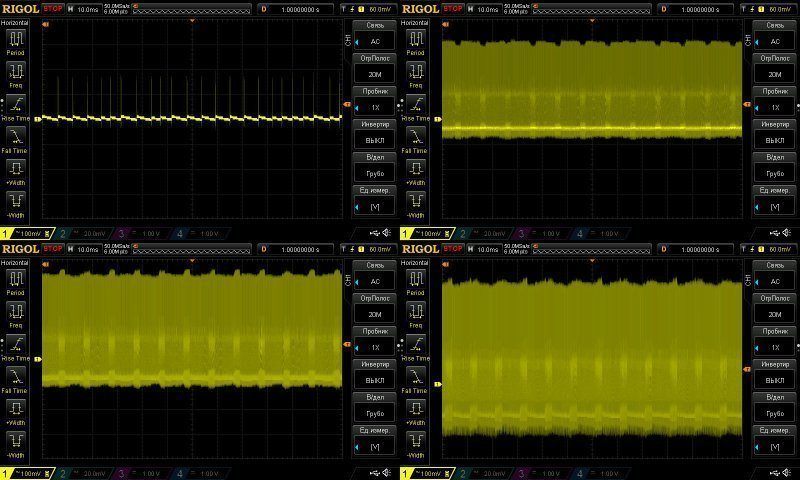
Everything looks fine at 100 Hz, but since the input capacitor is just barely large enough, I think things will look noticeably worse at 115 V.
I checked the temperature rise at 3, 4, and 5 A. The output voltage has a small negative temperature coefficient, about 60 mV, which is perfectly fine.

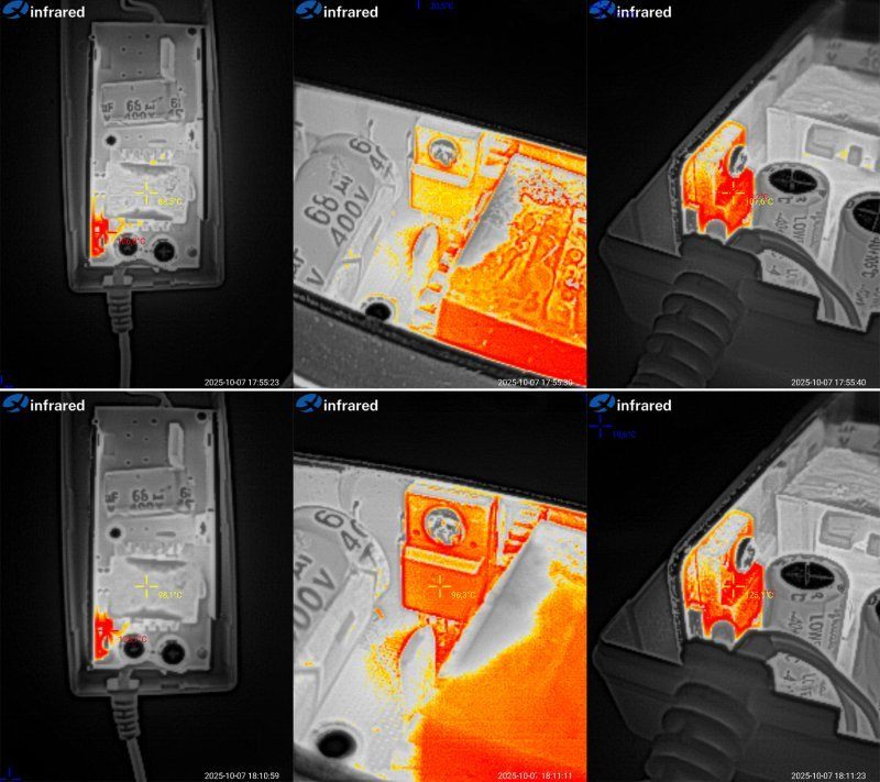
Temperature rise at 4 and 5 A.
At 4 A, the transformer reaches 89 °C, which is fine; the transistor reaches 85 °C, also fine; and the diode assembly reaches 107 °C, a bit high but tolerable.
At 5 A, things are of course worse. Efficiency is almost the same as with the previous unit, and the enclosure is the same size, but the power is higher. As a result, the transformer reaches 98 °C, right on the limit; the transistor reaches 96 °C, a bit high but tolerable; and the diode assembly reaches 125 °C.
In my opinion, this power supply's continuous current rating is no more than 4 A, and possibly less. Essentially, it's about the same as the previous one.
Model 1206, the most powerful one in this enclosure size: 12 V, 6 A.
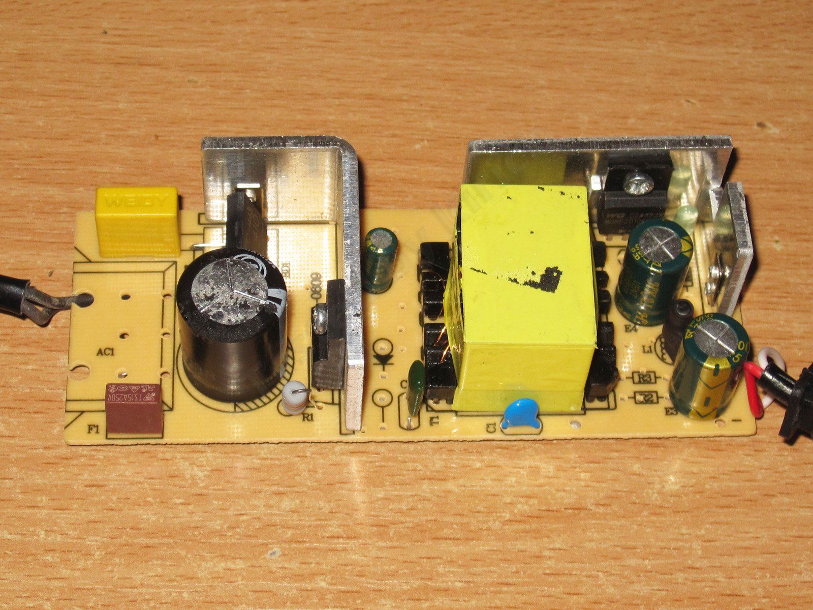
Now that's progress—they added an X capacitor :) But really, it's essentially the same design shown above, with a few minor tweaks.
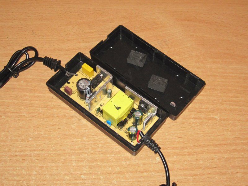
They used two L-shaped heatsinks instead of straight ones that run across the entire board. It's not a bad solution, though I've more often seen U-shaped heatsinks in power supplies like this, which are even better. The transformer looks pretty good; I can easily believe it’s rated for 60–70 W.
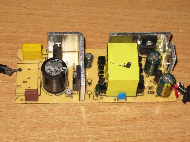
The input capacitor is 47 µF, clearly too little for the claimed power. It might just about be enough at 230 V, but there will be problems at 115 V.
The transistor is rated for 5 A and 65 V. Odd—the only one of the models shown above with this transistor was the 3 A version; the others use 7 A parts.
They used a regular high-voltage capacitor instead of a Y capacitor. The markings aren’t visible, but I can tell that anyway.
The output diode assembly is rated for 20 A and 100 V, which is fine overall.
The output capacitors are 1000 µF, 25 V. Unusual—16 V parts are more common. Nice.
Even nicer, there’s an output inductor to reduce ripple.

The underside is generally neat, though it’s disappointing that, as everywhere else, the wires are soldered to pads on the board rather than through holes. The wires are thin, too, especially the mains wires.

The input capacitor’s actual capacitance is 44 µF, so the marking is accurate. The output capacitance is fine too: we get 2000 µF.

The protection trips at around 7 A. That’s tolerable for a 6 A power supply, though something tells me it won’t deliver 7 A for long.
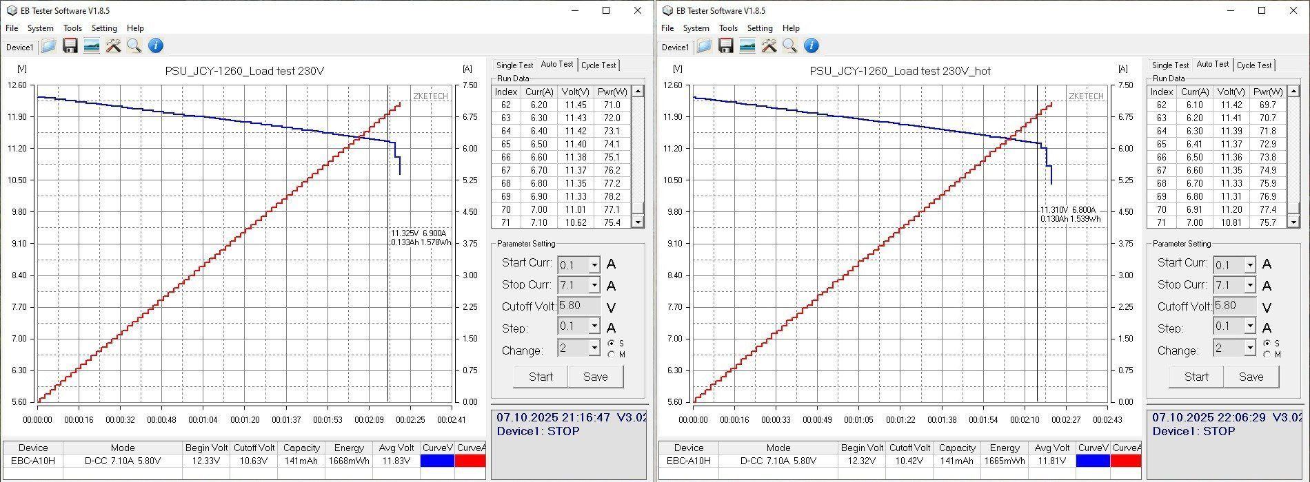
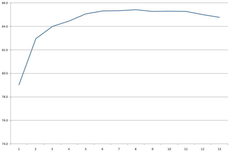
The no-load voltage is 12.33 V, and power consumption is 0.55 W. Under a load in the 0.5–6.5 A range, the voltage varies from 12.33 to 12.26 V, which is basically fine. But because of the thin wires at the connector, the voltage drop takes it from 12.33 down to 11.36 V.
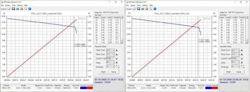
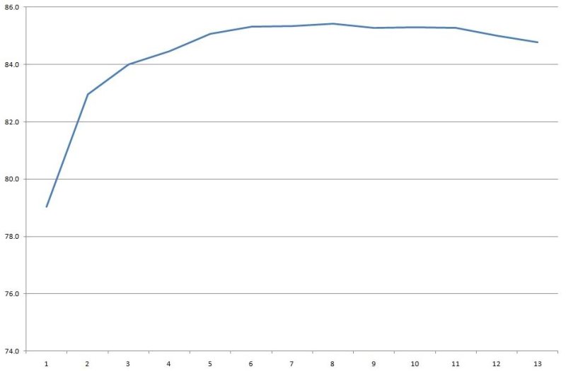
With the previous models, efficiency increased slightly as power went up. Here, though, it’s only 85%—rather low compared with the others.
Efficiency was measured from 0.5 to 6.5 A in 0.5 A increments.
As expected, high-frequency ripple is low. Measurements were taken with no load and at currents of 2, 4, and 6 A.
At 6 A, the main ripple is around 40 mV. There are short spikes, but they’re small too.

But at 100 Hz, things look unpleasant. The overall ripple seems similar to the previous models, around 350 mV, but it feels as if there’s no input capacitor at all—even though we measured its capacitance above. I later measured the ESR too and found nothing alarming, but the behavior is strange.
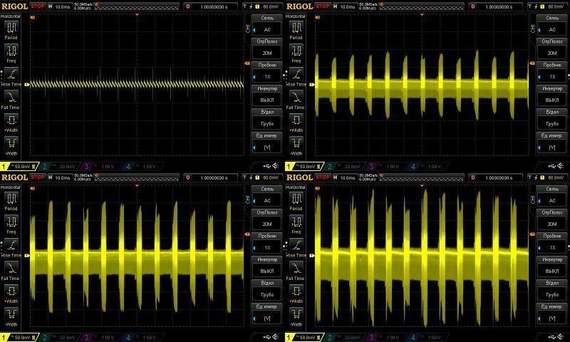
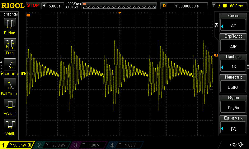
I should also note that when measuring high-frequency ripple, the waveform usually looked something like this. The fact that it looks almost normal above is more of a fluke.
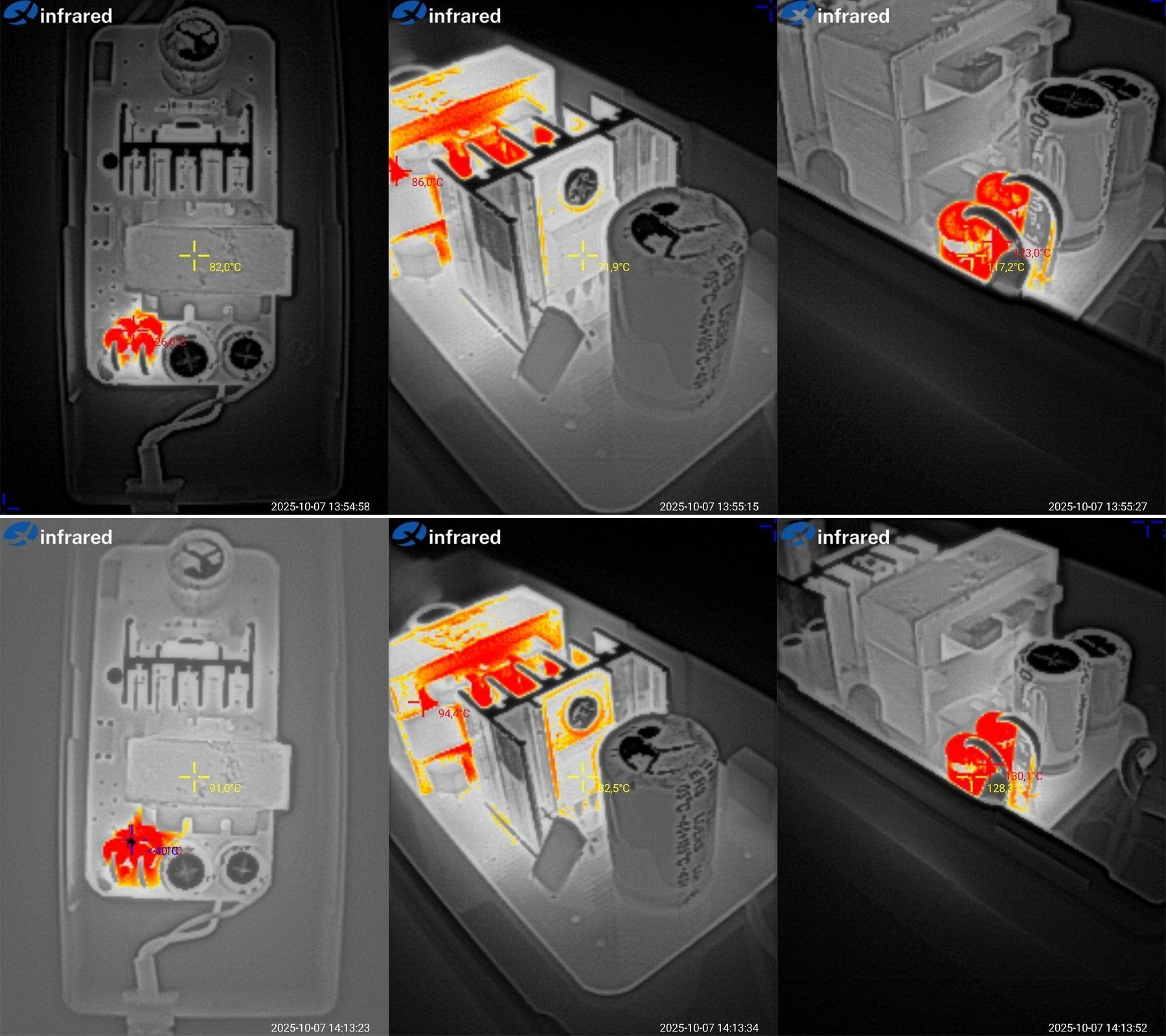
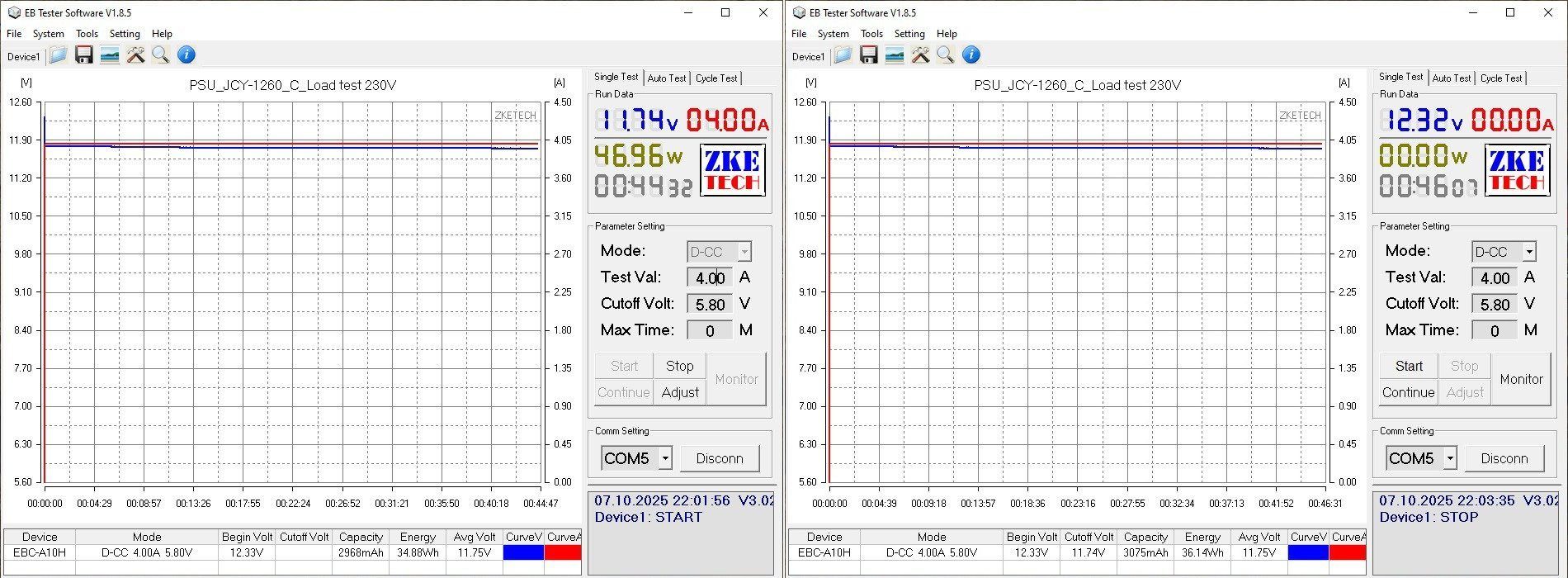
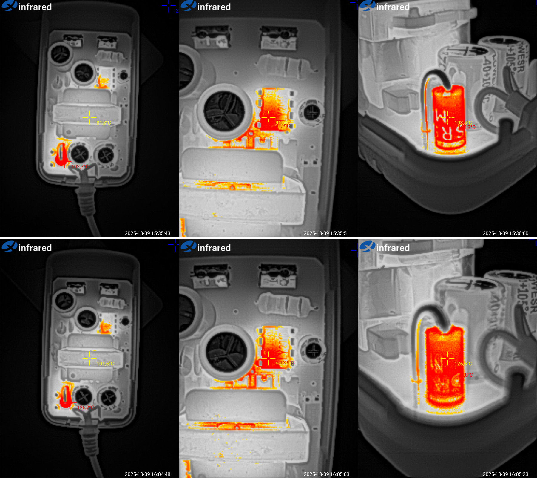
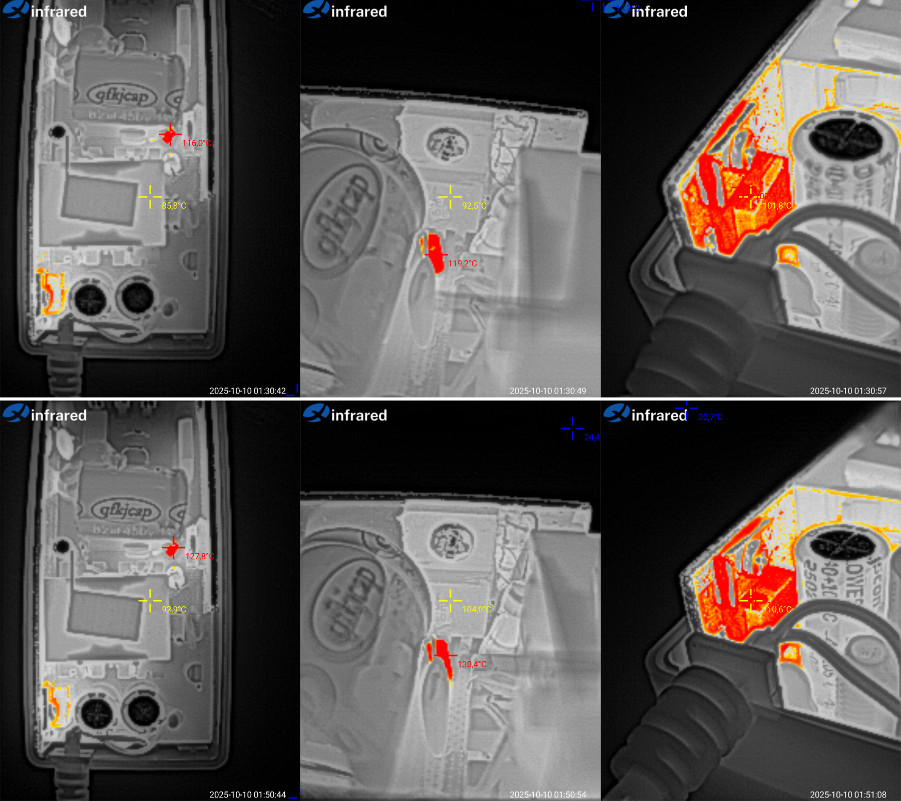
The thermal test was conducted at.... at one current value; the plan was to test at 4, 5, and 6 A, but the very first test changed everything.
Incidentally, the voltage barely depends on temperature.

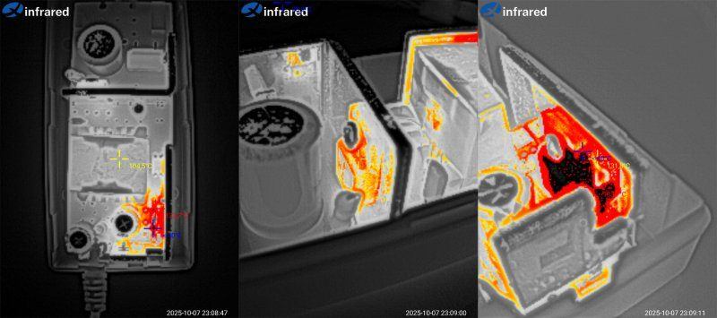
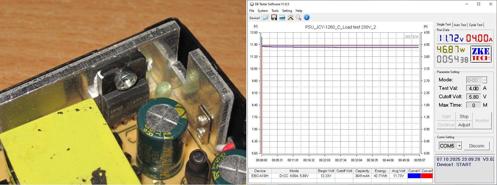
I stopped the test at 4 A for a reason: even at that current, overheating became apparent. After that, I didn't increase the current, but ran it in the same mode for a while longer.
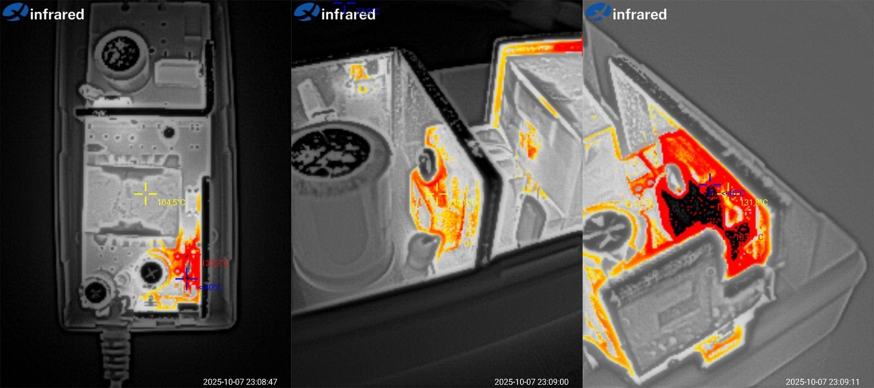
After a total of 45 minutes, the results were as follows (bottom photos): transformer at 97°C—not great; transistor at 101°C, also pretty high; and the diode assembly above 133°C. The thermal camera was off the scale—clearly too much.
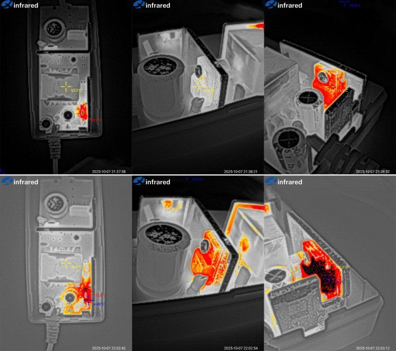
While inspecting the previous models, I noticed that none of them had thermal paste. So, as an experiment, I decided to fix that here, hoping it would bring down the diode assembly's temperature.
After that, I ran the power supply for about another hour.

At the same 4 A (the power supply was already slightly warm when I started), I got 105°C for the transformer, 113°C for the transistor, and over 133°C for the diode assembly.
The power supply overheating is a fact. What's less clear is why this one overheats at 4 A, while the previous models ran cooler at the same current—or at least no hotter.
All in all, it seems decent in some respects, but the severe overheating ruins the whole picture. This power supply can't even handle 4 A, let alone 6 or 7.
The fifth power supply is model 1207, rated at 12 V, 7 A.
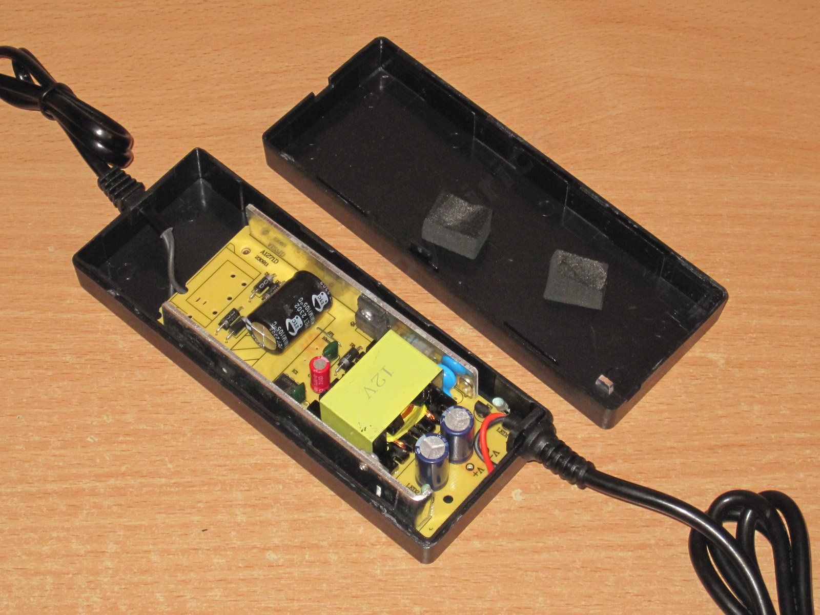
The case is a little larger, but the board inside is just as bare. By the way, I forgot to mention this about the previous one: the board was originally designed for an AC inlet, and personally I prefer that arrangement. But the manufacturer ended up soldering in a mains cable instead, and a rather thin one at that.
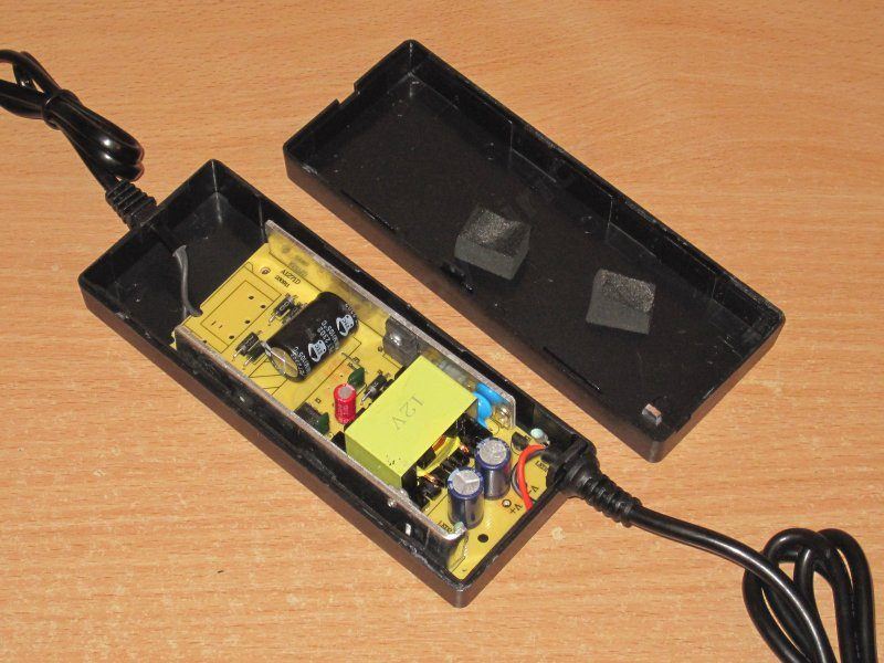
It really feels like they left out some parts :)
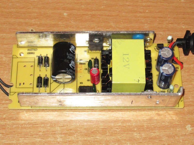
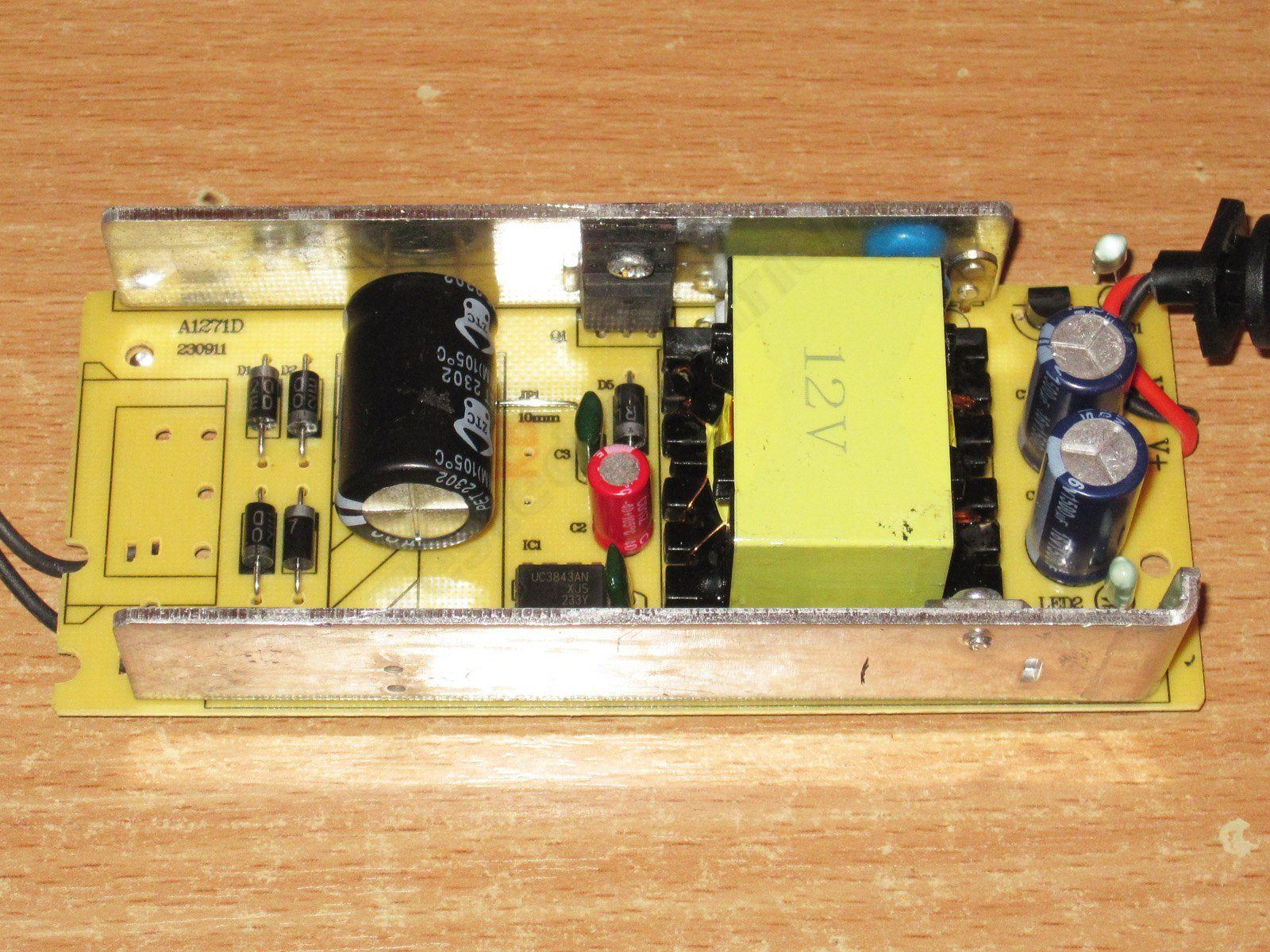
The input capacitor is 68 µF, and the transistor is rated for 10 A—not bad.
The diode assembly is rated for 30 A, and the output capacitors are 1500 µF, 16 V—also better than the previous models. The output capacitors are Aishi, too.
There is a Y capacitor; it's just not visible.
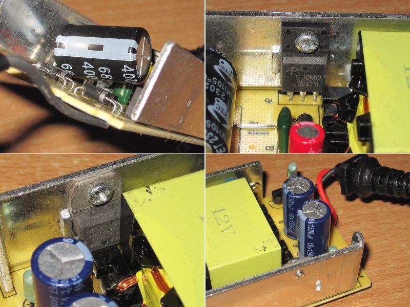
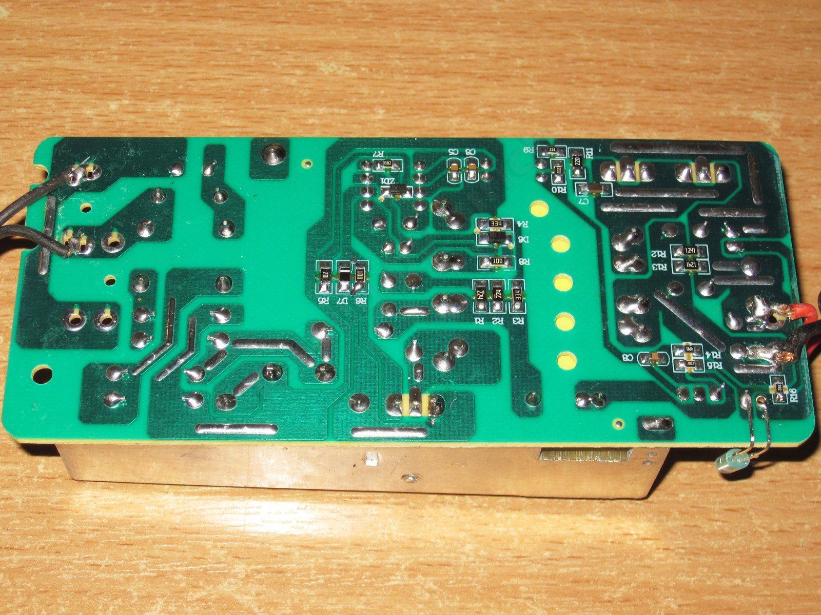
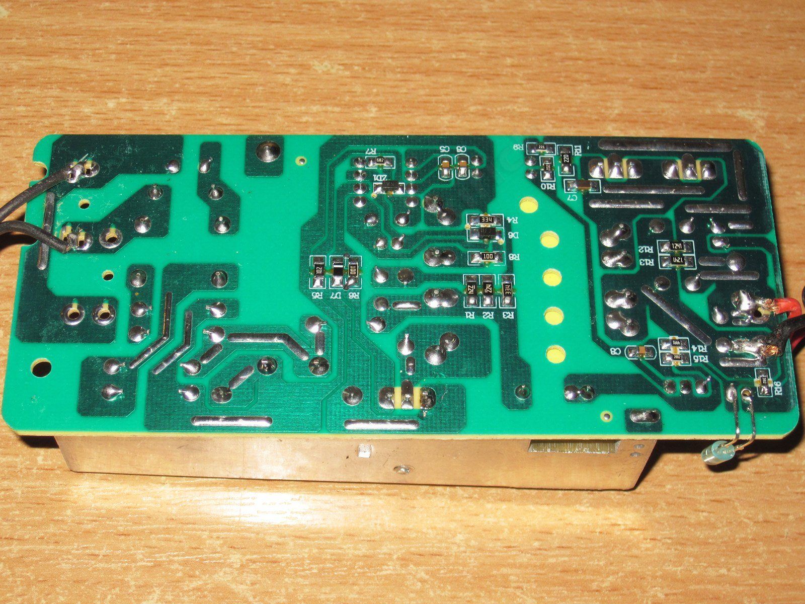
At first I thought the circuit board was like one of the previous versions, where I complained that one of the heatsinks was connected to the high-voltage section. But no: at first glance the clearances look very tight, but the transistor has an insulated case, so there's no major danger. The diode assembly heatsink's mounting point is also a good distance from the high-voltage section.
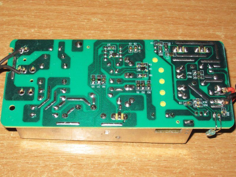
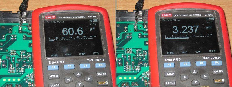
The input capacitor's actual capacitance is about 61 µF, while the output capacitance is closer to 3250 µF—more than specified.
The input capacitor's capacitance makes me suspect it's used and has already lost some capacity, since 61 is outside the tolerance for the specified 68. But I can't say for sure, although used components are common in power supplies like these. It's just enough for our mains voltage, though a close call; it would be too little for 115 V.
They installed two LEDs here as well, with one of them off to the side of the board instead of in its designated hole. The whole thing is a bit ridiculous: there are holes for the wires, so they solder them to the underside of the board; there's a designated spot for the LED, so they solder it on the side...
And yes, here's a clear example of redundancy: only one of the two LEDs works—and it's the one that isn't opposite the hole :)))

The overcurrent protection is set to about 6.8–6.9 A. When hot, the limit is even lower, around 6.5 A, so it will trip before reaching the specified 7 A. Maybe that's for the best.
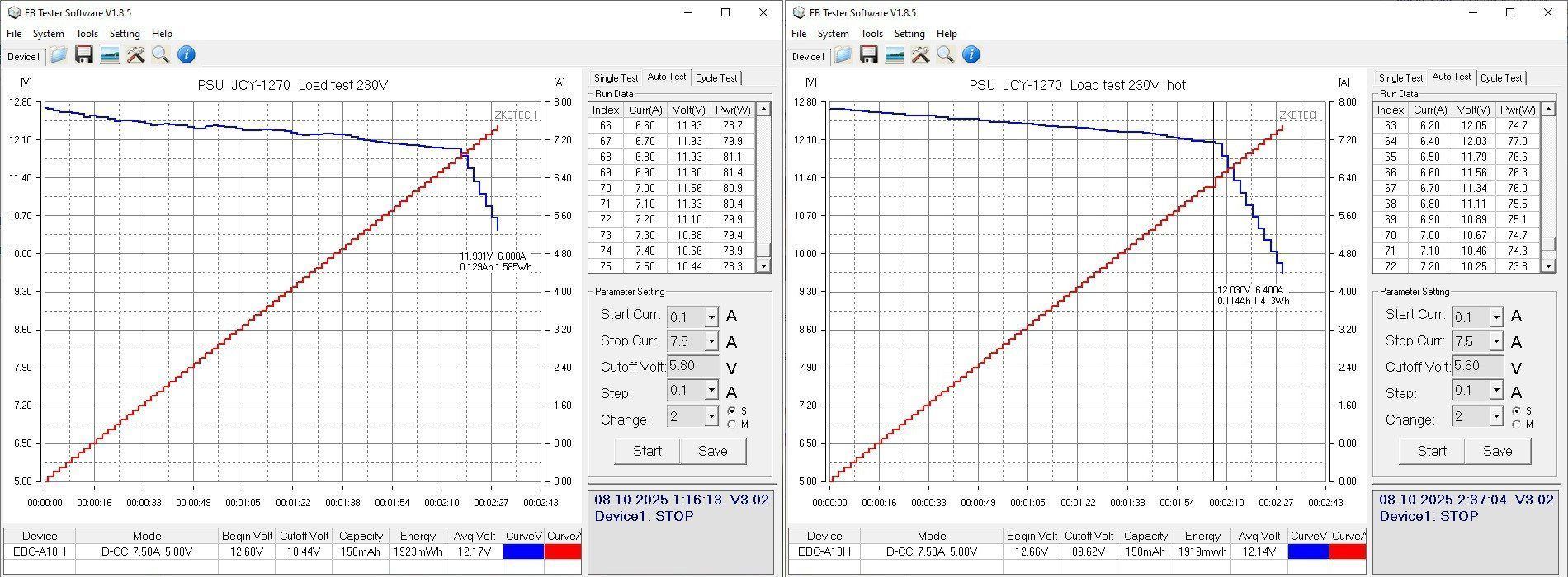
With no load, the output is 12.67 V, while power consumption is a hefty 1.55 W. I suspect that's down to the use of an ancient PWM controller.
I'll also blame that PWM controller for the strange fluctuations in voltage as the load current changes. The issue isn't that the voltage drops from 12.67 to 12.51 V as the load current goes from 0.5 to 6.5 A—that's perfectly normal. It's that the drop happens in waves.

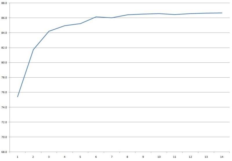
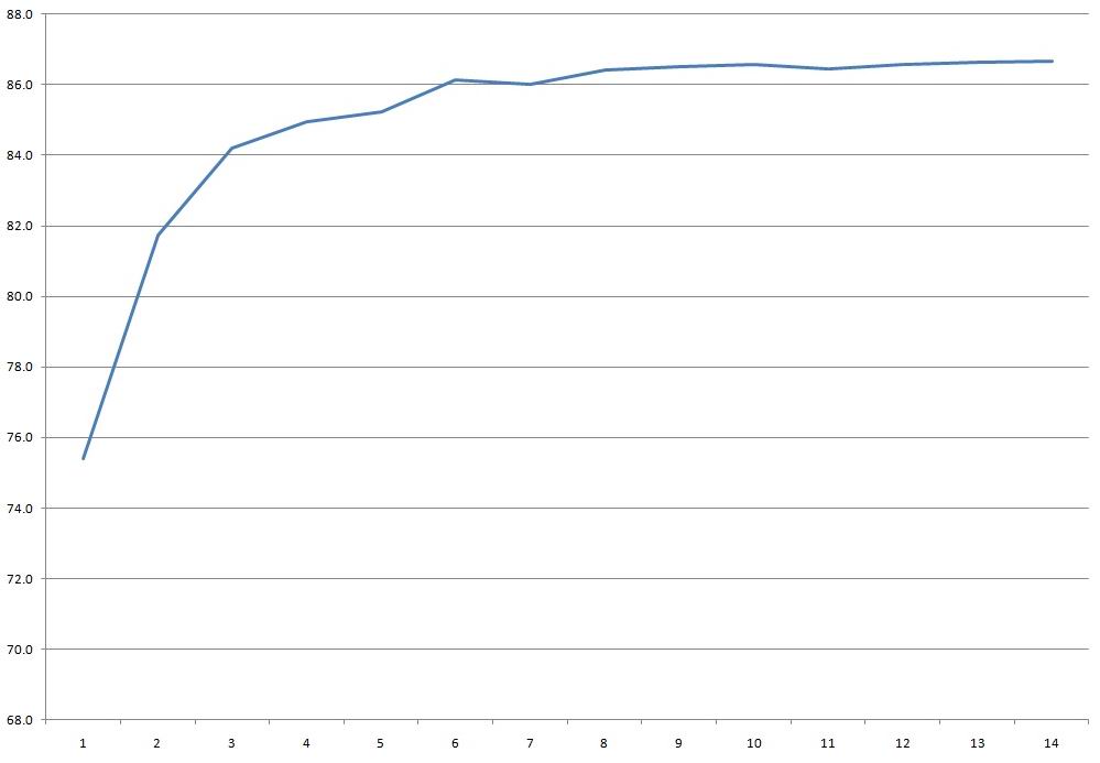
Even so, the power supply managed an efficiency just over 86%, although performance at low loads isn't great. And it's best not to run it with no load because of its high power consumption.
Efficiency was measured from 0.5 to 7 A in 0.5 A increments. At 7 A, the output voltage was 12.12 V.
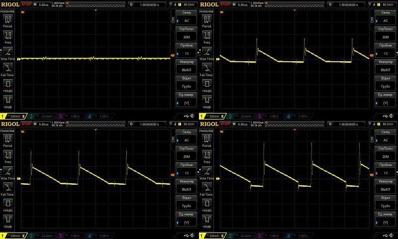
Ripple was measured with no load and at 2, 4, and 7 A. The results aren't great, in my opinion: even at 4 A, it's around 300 mV, and at 7 A it's almost 400 mV. As I wrote, these are perfectly fine for various lighting applications, and they’ll also do for powering small motors. But if you have anything sensitive, it’s better not to use them.
At 100 Hz, ripple only becomes noticeable at maximum power; otherwise, it’s perfectly acceptable.

I checked the temperature rise at currents of 4, 5, and 6 A. The output voltage does vary with temperature, but only very slightly.
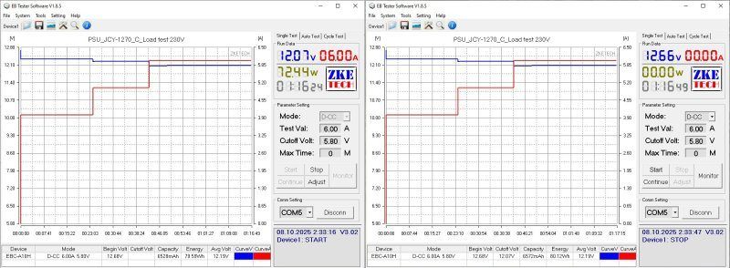
Test results at 5 and 6 A.
At 5 A: transformer, 83 degrees—fine; transistor, 70—also fine; diode assembly, 98—which is a bit much considering the current is only 5 A and the rating is 7 A.
At 6 A: transformer, 105—overheating; transistor, 92—fine; diode assembly, 115—a bit much, but tolerable.
Based on the measurements, this power supply is basically decent, but its working current is only around 5 A; above that, it will overheat.

And now the most powerful model in this lineup, the 1208, rated for 12 V at 8 A.
This one has a larger case, though it’s still half empty. And wow, they even added an input inductor. But, like all the previous models, it has no thermistor—and this one could definitely use one.

The layout is typical and doesn’t differ much from the previous models.

Yes, there’s an inductor and a capacitor, but oddly, they used discrete diodes instead of a proper high-power module. In short, cost-cutting.
The input capacitor is 82 µF, rated for 450 V—unusual. There’s no marking on the transistor at all, and it looks like it wasn’t rubbed off; it was never printed in the first place....
On the output side, there are two 20 A diode assemblies and three 1000 µF, 16 V capacitors. They’re branded, though I have my doubts that they’re new.
And yes, two LEDs again. What, did a truck full of LEDs overturn near the factory?
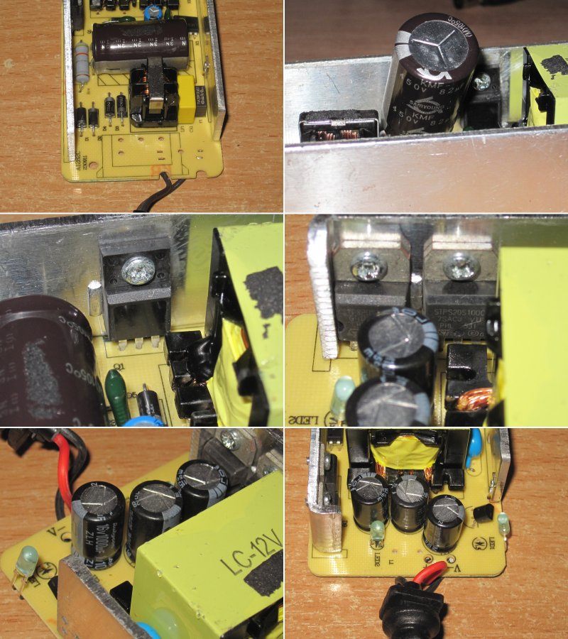
I have no major complaints about the circuit board layout; everything is relatively safe.

The input capacitor measures 75 µF versus the stated 82, but let’s put that down to measurement error. The output capacitance is noticeably higher than the expected 3000 µF, so it’s quite possible that the capacitors, even if not new, are at least in good condition.

And here are a couple of issues.
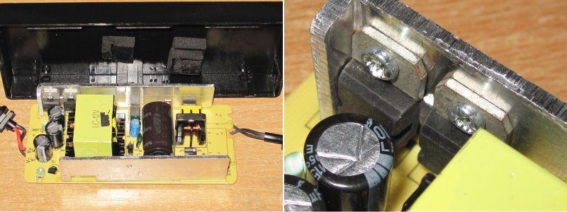
First, I noticed that the leftover piece of foam rubber that holds the board in the case doesn’t line up with where the rubber pad itself is installed.
Look closely and you can see adhesive residue on the input capacitor, while the rubber pad on the case is clearly farther to the right and couldn’t possibly have left that mark. So the capacitor is clearly used.
I also noticed that one of the output diode assemblies is clamped at an angle. It’s simply pressed against a protruding stop, with only the edge of its flange held down. We’ll see how it works, but I can already say that even if everything works fine, this kind of deformation could have cracked the case, and components like this shouldn’t be used.
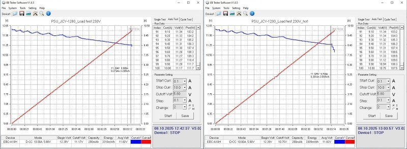
The protection current is set quite high: 10 and 9.8 A, practically right up against the maximum load current of 10 A. I was already starting to worry that I’d have to get another one out.
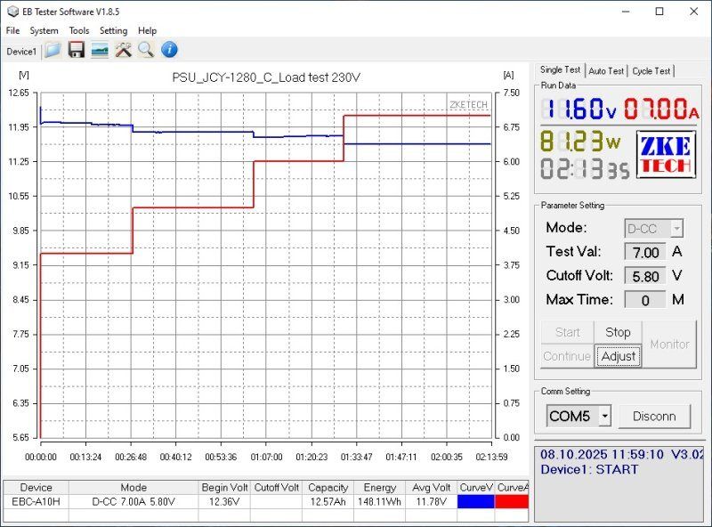
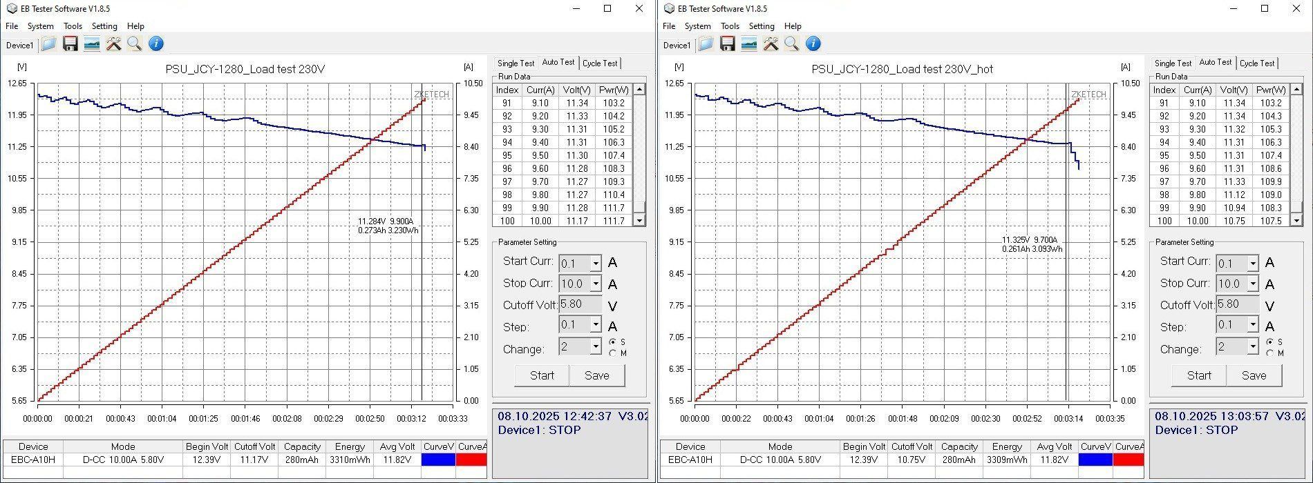
With no load, the voltage is 12.37 V and the power is 1.7 W. As the load current varies from 0.5 to 9.5 A, the voltage at the board’s own terminals drops from 12.37 to 12.06 V, which is quite significant. As with the previous model, you can also see the voltage fluctuating in waves. Generally, I hadn't paid much attention to these waveforms before, but in fact they're a characteristic of the PWM controller used, as is the high power consumption with no load. 1.7 W really is a lot.
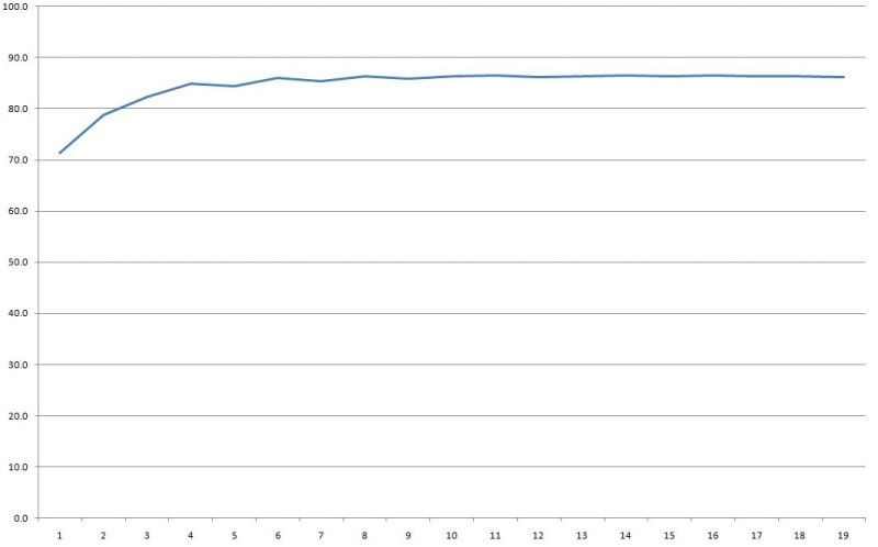
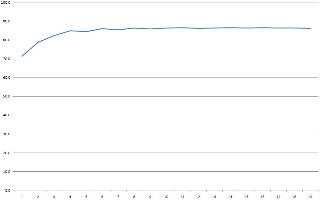
Even so, efficiency is around 86%, though it's clearly lower at the very lightest load because of the unit's own power consumption..
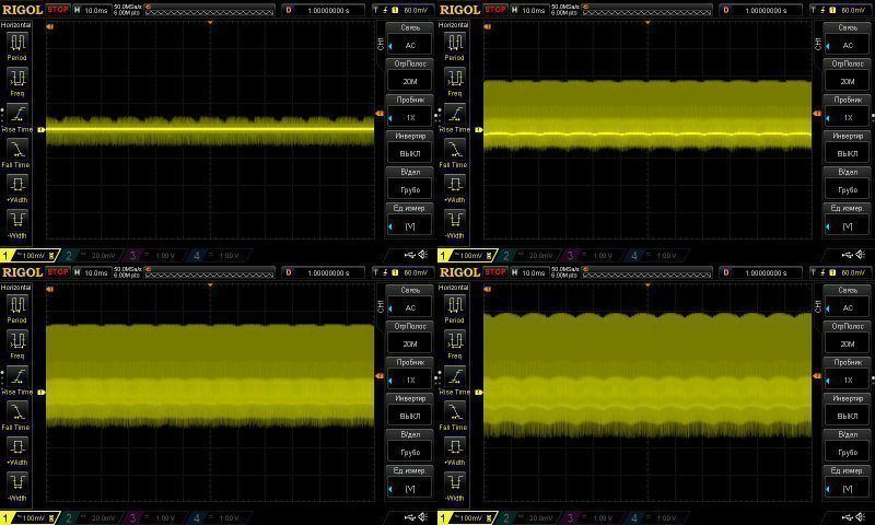
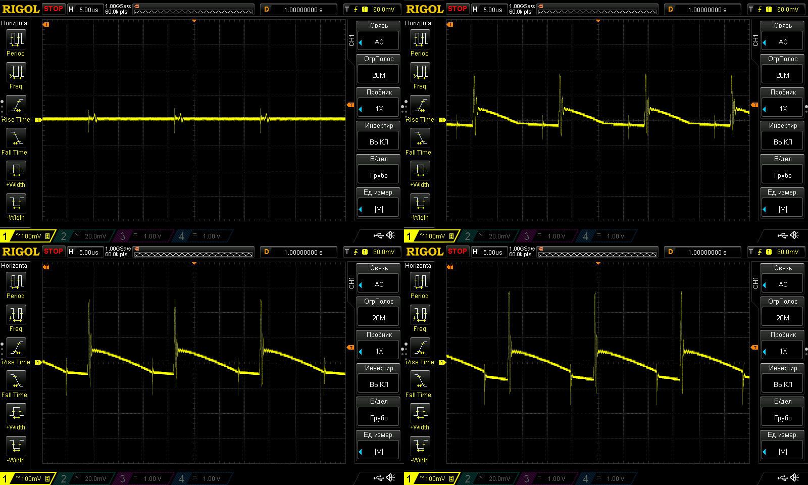
As for ripple, I'd say it's actually pretty good. I checked with no load and at 3, 6, and 8 A. At the maximum current, ripple was around 100–120 mV. Since there's no filter here, that's clearly thanks to the good capacitors.
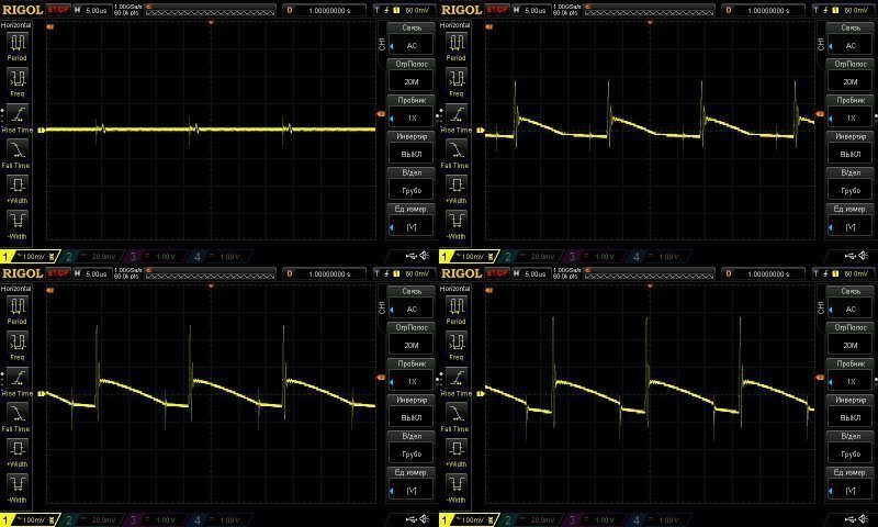
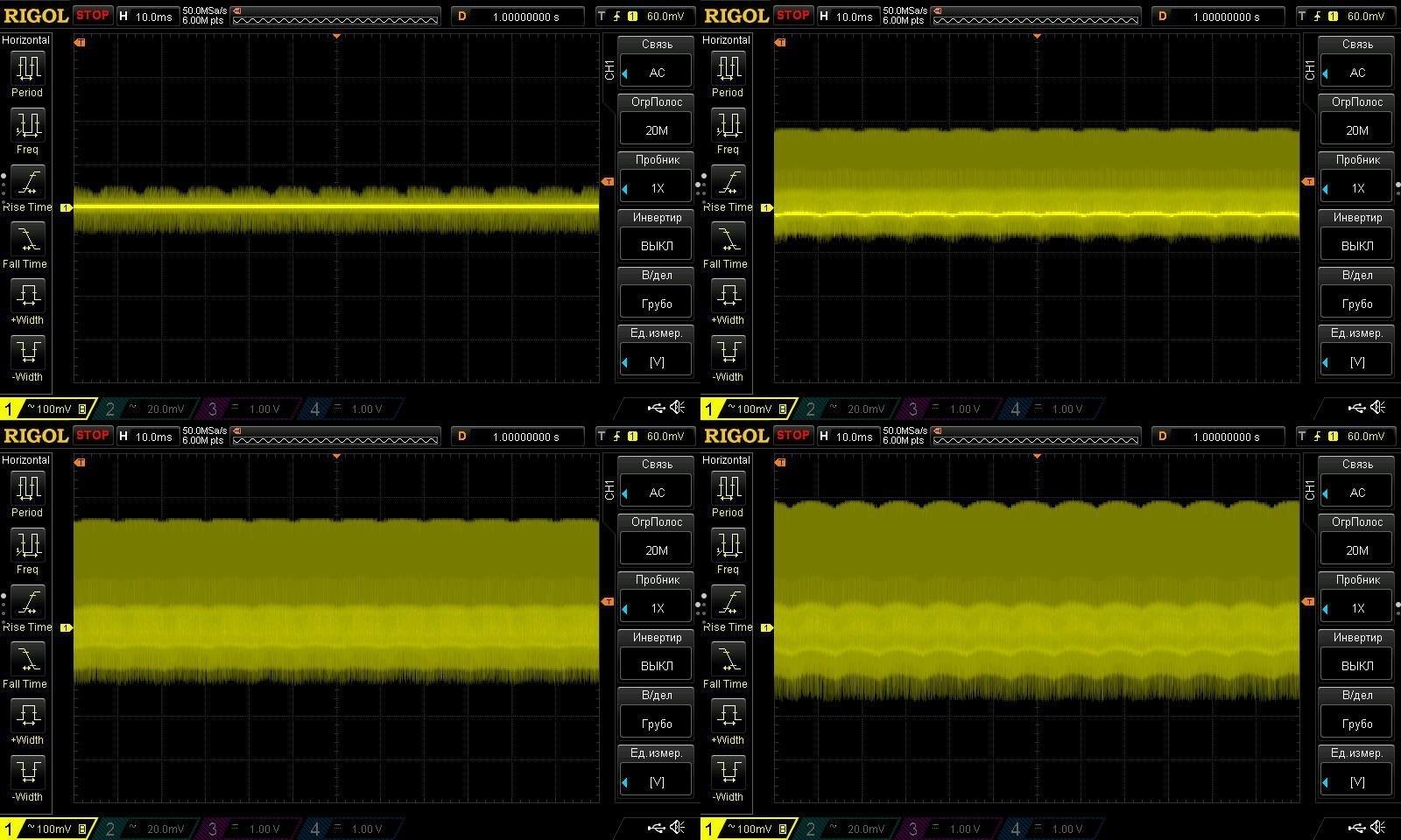
At 100 Hz, it also looks fine.
I checked the temperatures at 4, 5, 6, and 7 A. I forgot to take a screenshot after removing the load, sorry.
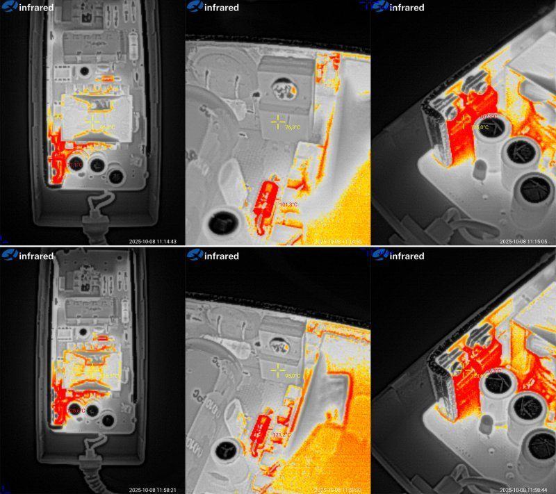
Test results at 6 and 7 A.
At 6 A: transformer, 96°C—rather hot; transistor, 76°C—fine; diode assemblies, 105–107°C. Interestingly, the one that's clamped crooked is cooler. Maybe that was intentional?
At 7 A: transformer, 115°C—severely overheated; transistor, 95°C—acceptable; diode assemblies, 125°C and 126°C—too hot. I wouldn't push it any harder.
So, for this power supply, I'd say its actual output current is no more than 6 A. It can deliver more for a short time, but I wouldn't recommend it. The protection isn't set up very safely either, so it's easy to kill the unit by overheating it.
Now for the power supplies I've already had in for review and that have had some changes made to them, mostly to the components and their ratings.
There are four models here, all 12 V, rated for 1, 2, 3, and 4 A.

Two are plug-in wall adapters, while the other two use a standard power cord.
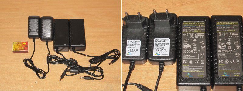
I'll start, of course, with the smallest one, AD-12-1A — price: 63 UAH — link
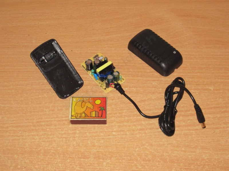
There's not much to it, though given the price, you probably shouldn't expect anything more. Still, what matters more are the specs and build quality.
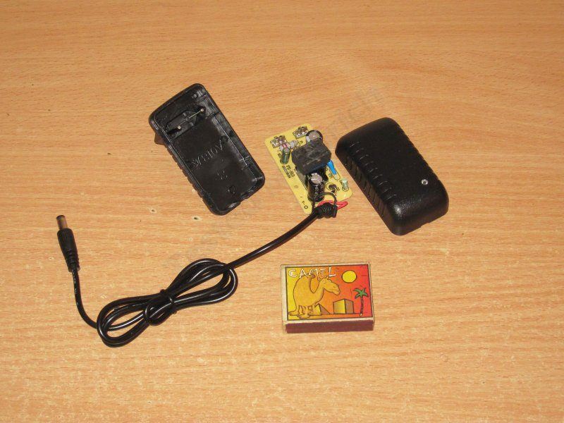
There's no fuse as such; its job is done by a fusible resistor, which also limits the inrush current.

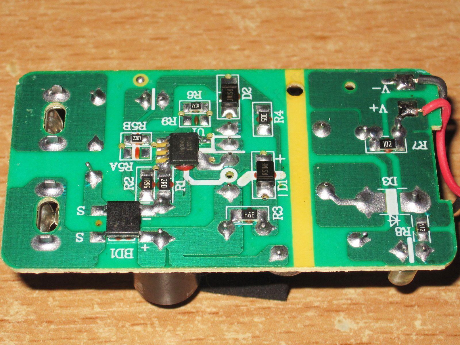
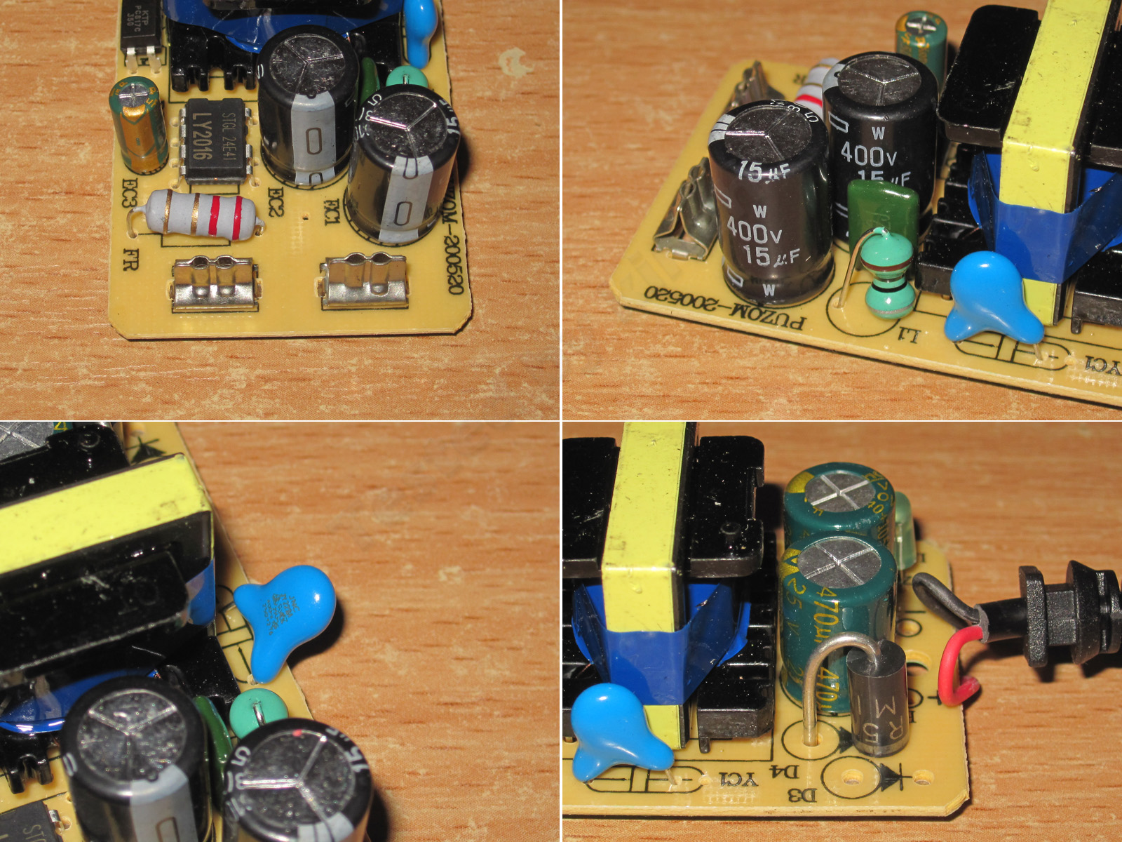
The input capacitor is 15 µF, 420 V, which gives plenty of margin for the rated power and our mains voltage. I think it would also work at 115 V, though with a slight reduction in power.
There's a Y capacitor. The output diode is a bit undersized, though I'll get to that later.
The output capacitor is 470 µF, 25 V. As with the other models, the wires are soldered to the underside of the board :(

I have no concerns about electrical safety. I would point out two things, though. First, there's no feedback optocoupler, so we'll check the voltage regulation accuracy later. Second, it uses an integrated PWM controller. I consider a PWM controller with a built-in high-voltage transistor an advantage, since it also has a thermal sensor, so I have no concerns about its protection.
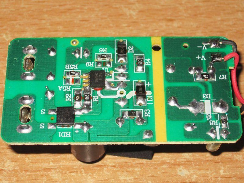
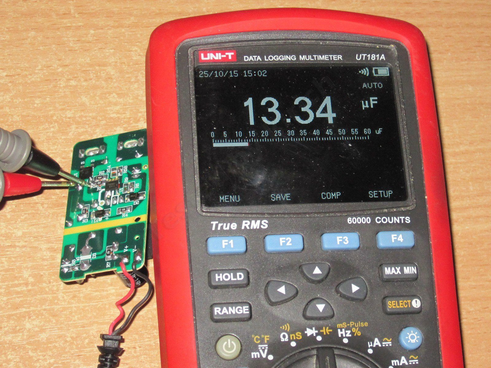
For some reason, I couldn't get a reliable measurement of the output capacitor's capacitance with my multimeter, and I couldn't be bothered to get another instrument. The input capacitor's capacitance is essentially as specified.

The power supply goes into protection above 1 A. It handles 1 A without any problems, but the protection trips at 1.1 A. Yes, it's right on the limit, but maybe that's a good thing.
With no load, the output voltage is 12.12 V and power consumption is 0.4 W. As the load increases from 0.2 to 1 A, the voltage changes from 12.12 to 12.43 V. The power supply does have some compensation for voltage drop in the wires (probably parasitic), although the graph clearly shows when it suddenly raises the voltage.
Overall, I have no complaints about its stability.

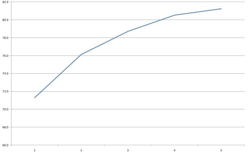
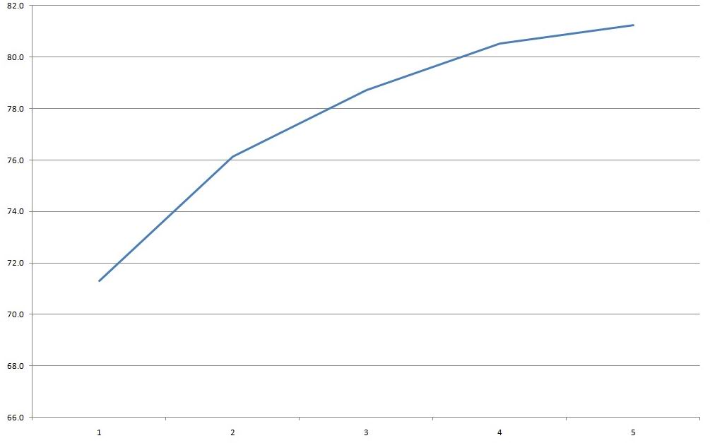
In my opinion, efficiency is low. I expected more, though the relatively large measurement error may also have affected the result. I measured from 0.2 to 1 A in 0.2 A increments.
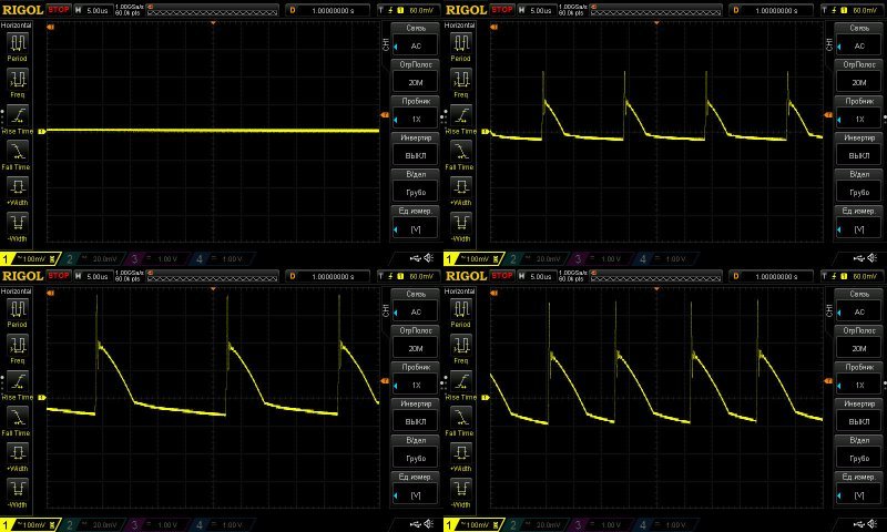
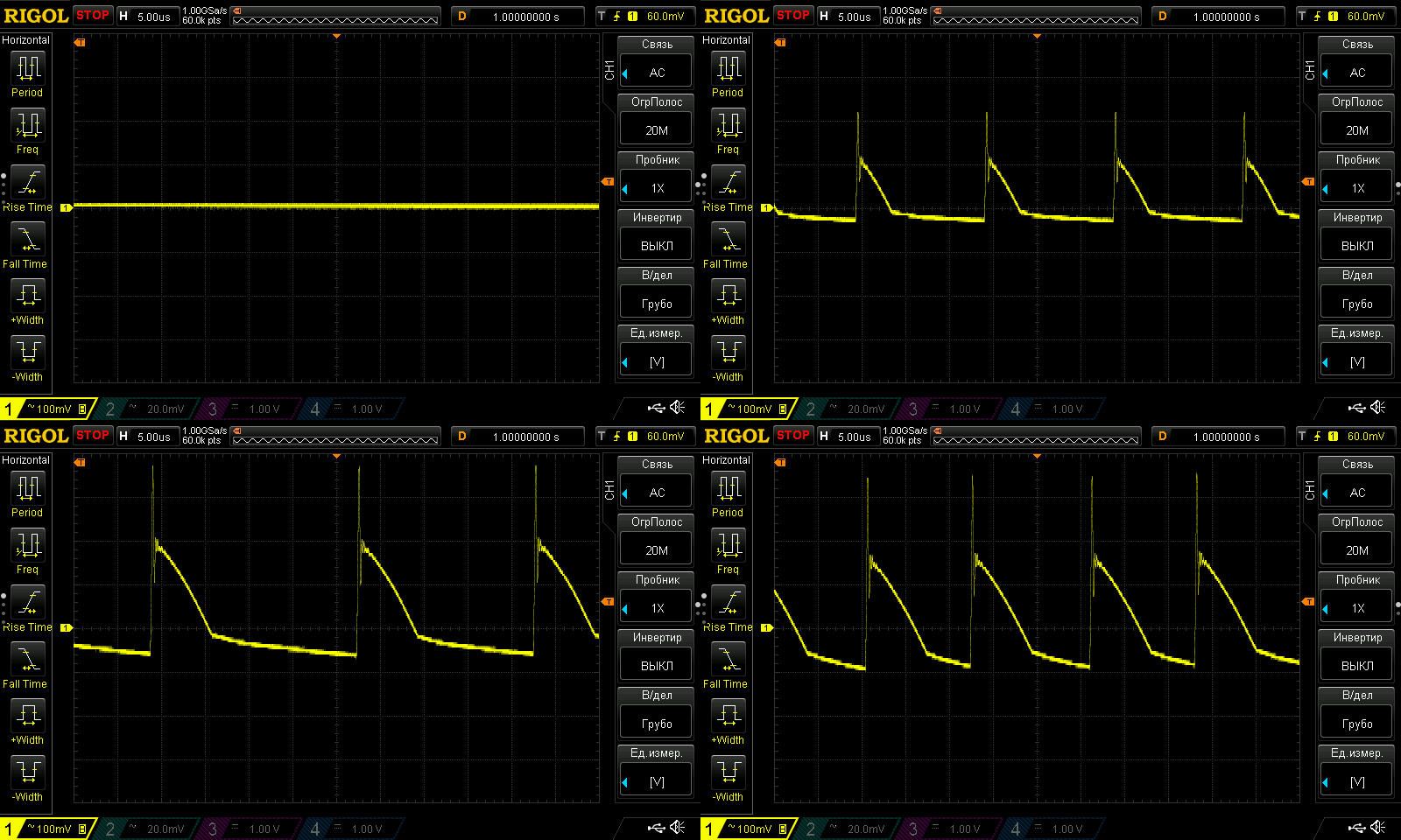
Ripple was checked with no load and at 0.3, 0.6, and 1 A. At maximum power, I measured about 250 mV. That's a bit high for a power supply of this rating, but overall it's perfectly acceptable.
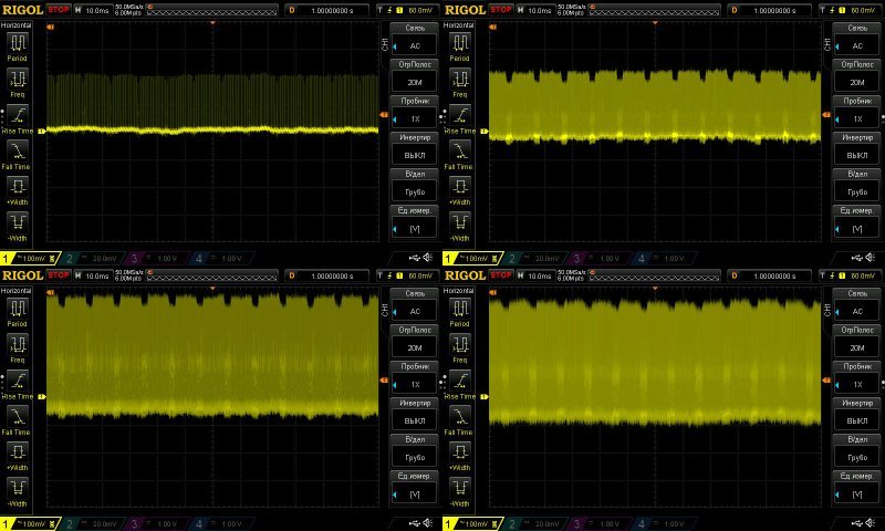
I have no complaints about the 100 Hz ripple; everything is as expected and within acceptable limits.
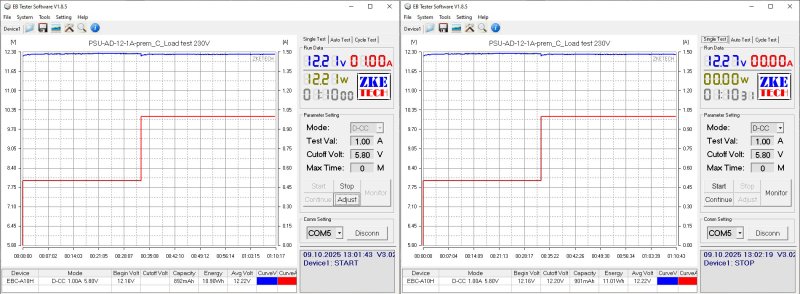
The thermal test was run at currents of 0.5 and 1 A, for about 30 and 40 minutes at each stage.
The output voltage rises with temperature by about 110 mV. I wouldn't call that critical, especially given the lack of proper feedback.
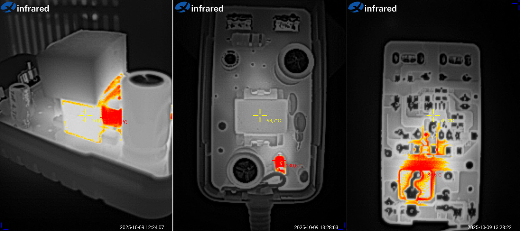
Below are three thermal images. The first shows the transformer at 0.5 A: just 62 degrees. The second and third were taken at 1 A: the transformer is at 94 degrees, which is fine; the output diode is at 130 degrees, which is too hot; and the PWM controller is at 70 degrees, which is excellent.
A couple of words about the diode. I wrote above that it's a bit undersized, and in the preliminary tests on the sample its temperature was slightly lower, otherwise I would have noticed. Here, I recommended either replacing it with a more powerful one or adding a second identical diode in parallel. The difference in cost would have been just 3–5 cents, since a 3 A diode costs us about 6 cents at wholesale.
That said, if the power supply is used at currents of 0.7–0.8 A, the diode that's already installed will be more than enough.

The second power supply, AD-12-2A, costs 93 UAH — link.
The case is a little larger, and there are some noticeable changes to the components as well.
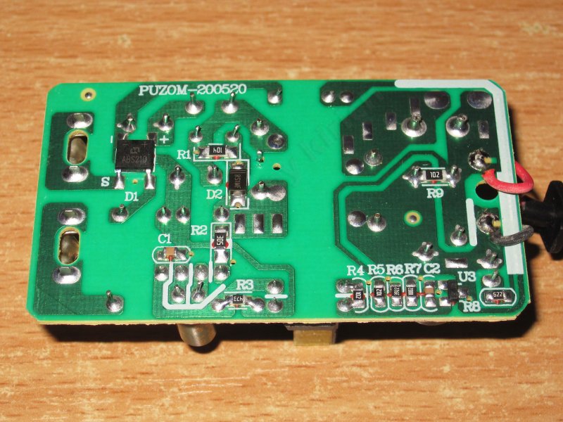
A fusible resistor is used as the fuse here too, but there are two input capacitors and an inductor, forming a CLC filter.

The PWM controller is a more substantial one; these are often used in supplies rated around 24 W, so no concerns so far. This one also has optocoupler feedback.
The input capacitors are the same type as in the previous model, but there are two of them here, for a total of 30 µF, which is more than enough for 24 W.
There is a Y capacitor, and the output has a pair of 470 µF, 25 V capacitors to improve reliability.

The circuit board is neatly made, and I have no safety concerns either.
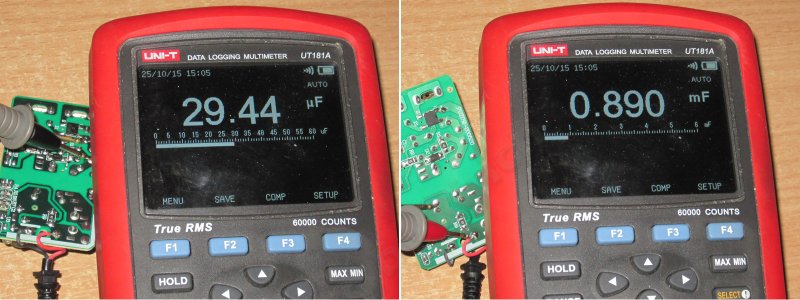
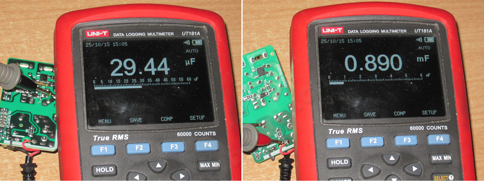
The actual input filter capacitance is almost 30 µF, and the output capacitance is 890 µF; both are within the measurement error.
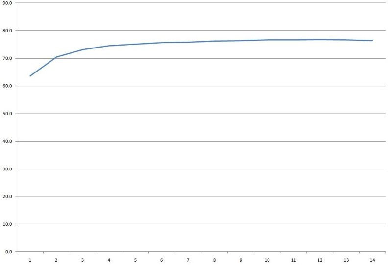
The protection current is determined by the installed PWM controller and is about 3 A or 2.8 A, depending on how hot the power supply gets.
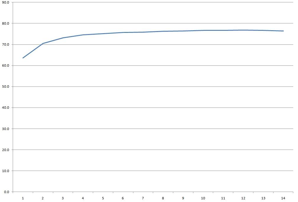
With no load, the output voltage is 12.29 V and the power consumption is 0.5 W. Output voltage stability at the board terminals is perfect: across a load range of 0.2 to 2.8 A, the voltage stayed between 12.28 and 12.29 V. Note that this was even with an overload of almost 50%.

The efficiency, however, isn't very high—about 76%. It could be better.
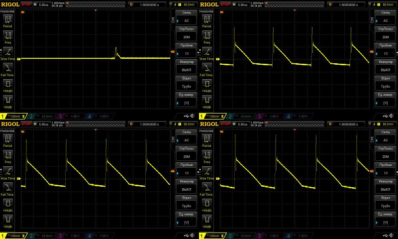
High-frequency ripple with no load and at currents of 1, 1.5, and 2 A.
At maximum power, we get about 250 mV. That's rather high, but still within the tolerance for budget power supplies. An inductor between the capacitors would improve things, but there isn't one here, and there's no room for one either.
No complaints about the low-frequency ripple; it's all as expected. The only odd thing is the waveform, which looks a bit like a picket fence.
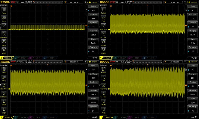
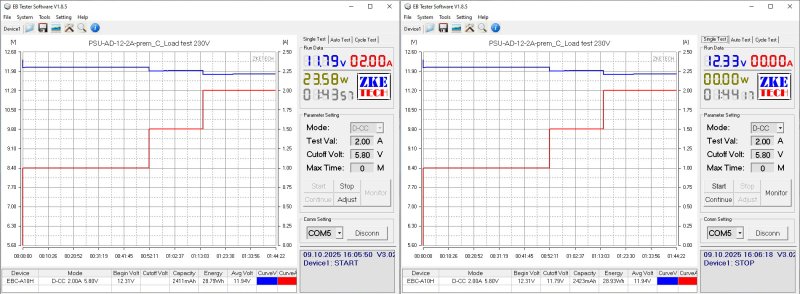
The load test was run at currents of 1, 1.5, and 2 A. The output voltage rises with temperature, but by only 20 mV, so you can pretty much ignore it.
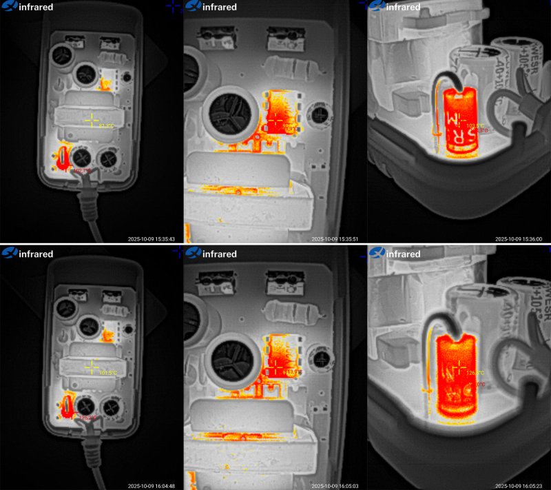
And now the temperatures of the main components. Below are photos taken after the tests at 1.5 and 2 A.
At 1.5 A: transformer, 81 degrees—excellent; PWM controller, 92 degrees—acceptable; output diode, 104 degrees—acceptable.
At 2 A: transformer, 101 degrees—hot, though there's a little headroom; PWM controller, 114 degrees—a bit too high; output diode, 128 degrees—hot.
In practice, there's no need to worry about the PWM controller's temperature; it has thermal protection as a last resort. The output diode, however, runs too hot. I strongly recommend adding a second identical diode in parallel. This will reduce heating slightly thanks to the lower voltage drop and better heat dissipation, and may also bring the transformer temperature down by a few degrees.
i.e. This power supply can probably handle 2 A continuously, but it’s better to limit it to 1.7–1.8 A. It’s quite possible that adding a 5-cent diode will let it deliver 2 A continuously.
AD-12-3A power supply, 12 V 3 A, price: 167 UAH - link
This one has a case designed for a standard mains cable, which is good.

The input has a filter consisting of an inductor and a capacitor, and they’ve also added a thermistor. The input capacitor is secured with glue, and there’s thermal paste under the power components.
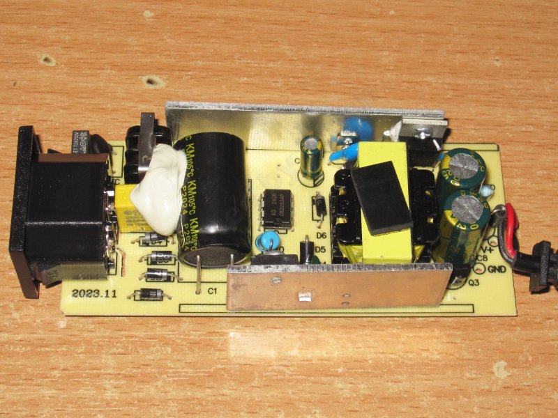
The input capacitor is glued in place. I think it’s 68 µF, but it was awkward to check, so I’ll measure it later.
Judging by the markings, the transistor is probably rated for 10 A and 600 V. Next to it is a current-sense resistor; I think you selected its value to set the optimal protection current.
There’s a Y capacitor, but it’s positioned quite close to the heatsink. More on that later.
The output rectifier is rated for 10 A, which is perfectly adequate. The output capacitors are 1000 µF 25 V, and there’s even a small inductor made from a ferrite tube. It’s tiny, of course, but better than nothing. We asked the manufacturer to use 25 V capacitors instead of 16 V ones, which improves reliability.
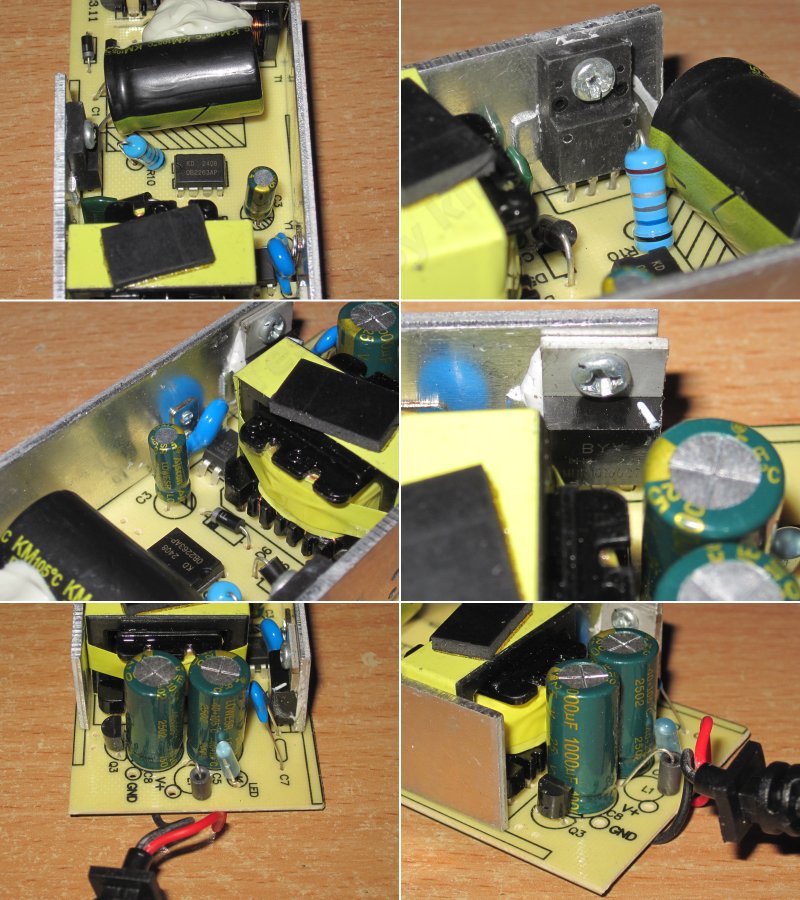
At first glance, the circuit board is well and properly laid out. It even has safety slots.
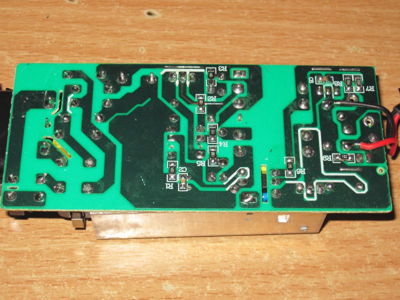
Unfortunately, there is a safety issue. I wrote about it when I first started working with this model, and I’ll mention it again now.
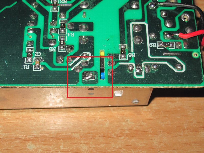
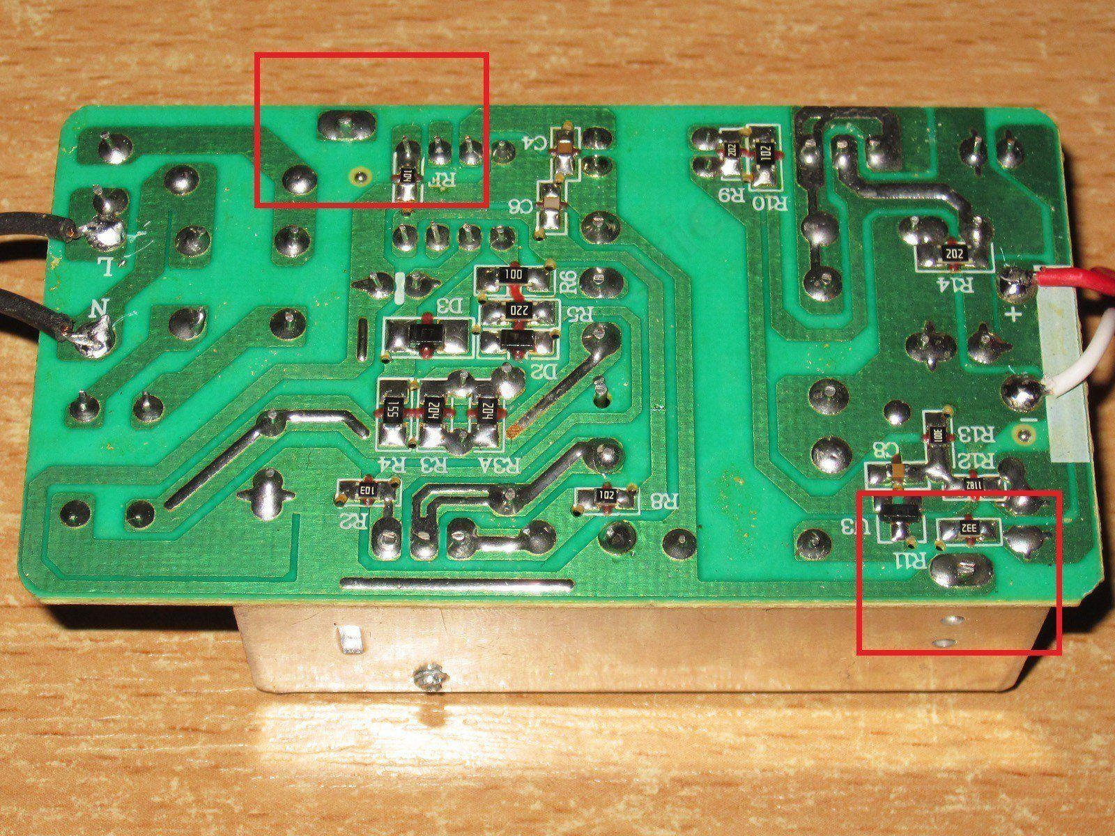
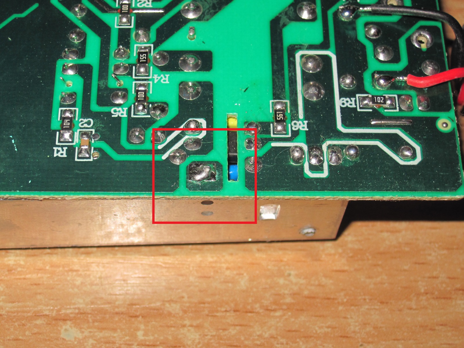
The highlighted copper area in the photo is where the lead that holds the heatsink is soldered. The heatsink carries a rectifier in a non-insulated package.
Without modifying the circuit board (essentially, the heatsink just needs to be moved about 10–15 mm to the right so that its mounting lead is on the cold side of the optocoupler), the alternatives would be:
1. Use a rectifier in an insulated package; the price difference is just a few cents.
2. Coat the board with protective varnish. I can’t say how much that would cost, but I think it would simply be impractical to manufacture.
The right solution is free: move the heatsink. For now, I wouldn’t recommend using this power supply where you could touch the output terminals and something grounded at the same time—for example, the floor or a wall.
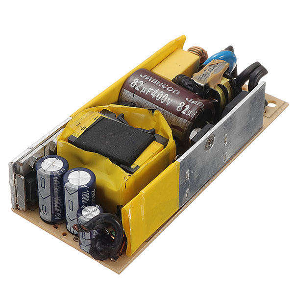
A simple, effective way to prevent a short to nearby components is to put insulating tape on the heatsink. Inside the case, it doesn’t significantly affect the heatsink’s performance.
The measured input capacitor value is 60 µF. That’s more than enough for 36 W, and it’s fine even with a 115 V input. The output capacitance is about 2100 µF—excellent.

The overcurrent protection is set to about 3.9–4 A. You’ll see later why it’s set that way.
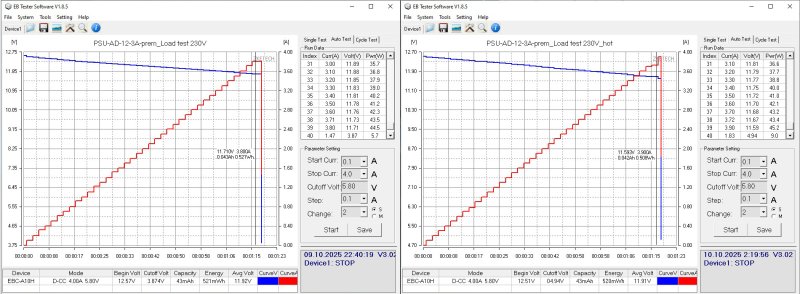
The no-load output voltage is 12.54 V, and power consumption is 0.45 W. With loads from 0.5 to 3.5 A, the output voltage at the board terminals varies from 12.48 to 12.33 V.
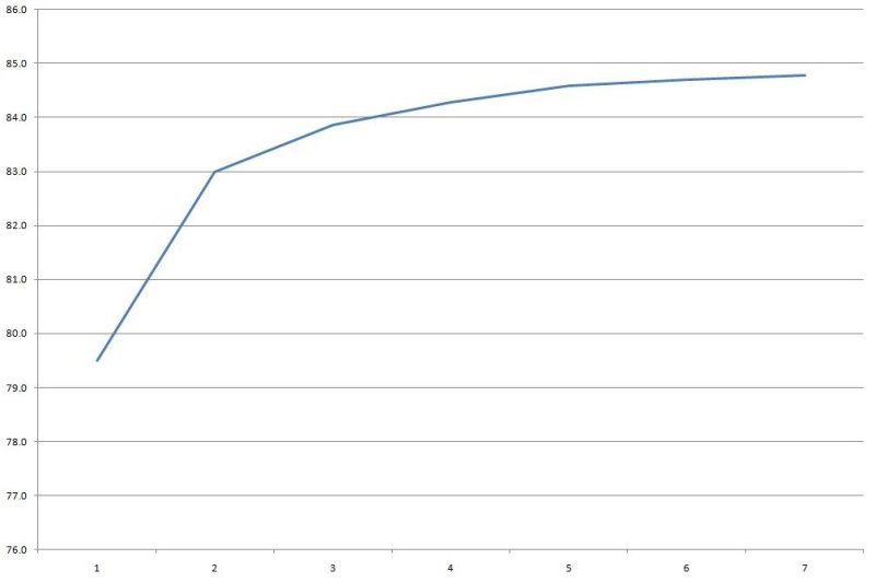
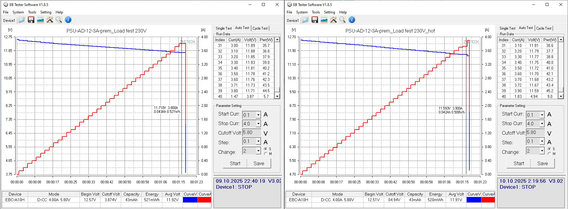
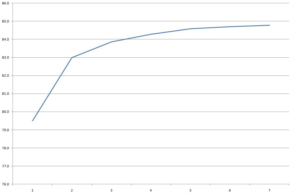
Efficiency is pretty typical, around 84%. Measurements were taken from 0.5 to 3.5 A in 0.5 A increments.
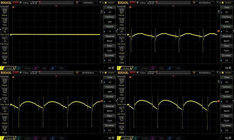
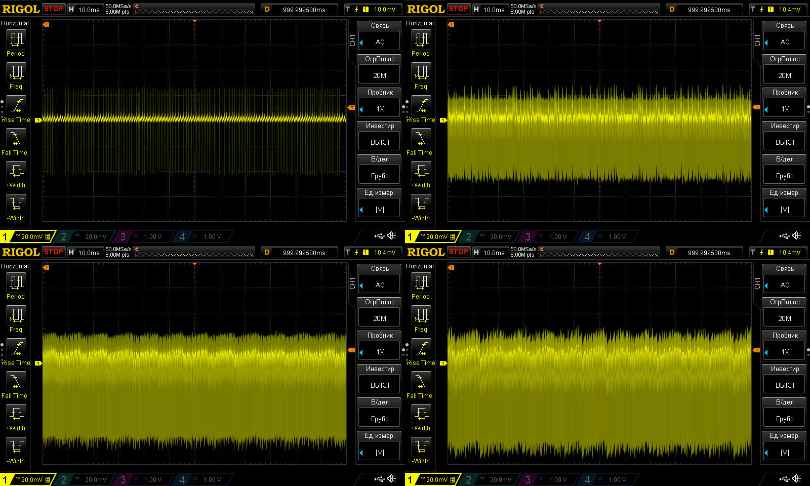
High-frequency ripple at no load and at currents of 1, 2, and 3 A.
Even at maximum power, the main ripple component is only about 30 mV. There are some “spikes,” but their amplitude isn’t very high either. The generous output capacitance helps, as does even the “laughable” little inductor.
The 100 Hz ripple is also fine, thanks to the generous input capacitance.

Interestingly, the “green” mode operates at a relatively high frequency. By the way, all the power supplies tested run quietly, both at no load and in every operating mode.

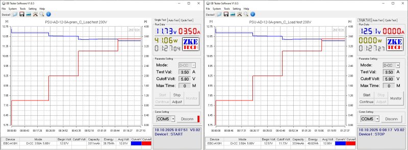
Temperature rise was checked in four modes, at currents of 1, 2, 3, and 3.5 A. The output voltage does vary with temperature, decreasing by about 60 mV in total.
Temperatures at 3 and 3.5 A.
3 A: transformer 78 °C, excellent; transistor 72 °C, excellent; rectifier 88 °C, excellent.
3.5 A: transformer 86 °C, excellent; transistor 80 °C, excellent; rectifier 101 °C, very good.
We set the protection current experimentally so that the power supply wouldn’t overheat in any operating mode. In other words, either the temperature stays within normal limits or the protection trips—and it isn’t set right on the edge; there’s some margin too. I think we got it right: although rated for 3 A, the power supply can easily deliver 3.5 A continuously, and even more.

And finally, the last power supply, AD-12-4A, priced at 195 UAH - link
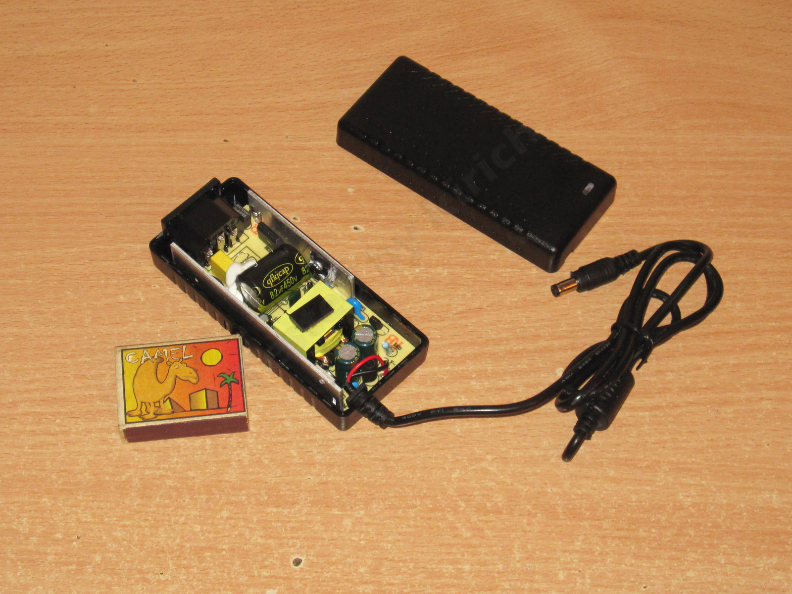
In many ways, it resembles the previous one, but it has no input filter. This was a somewhat necessary compromise, but it does have an input thermistor, which in my opinion is much more important. It also has a decent bridge rectifier to improve reliability.
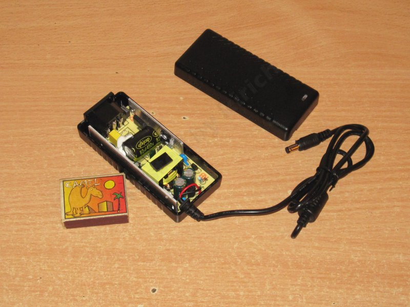
The layout is reasonably compact, and the input capacitor is secured as well.
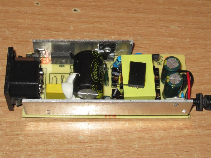
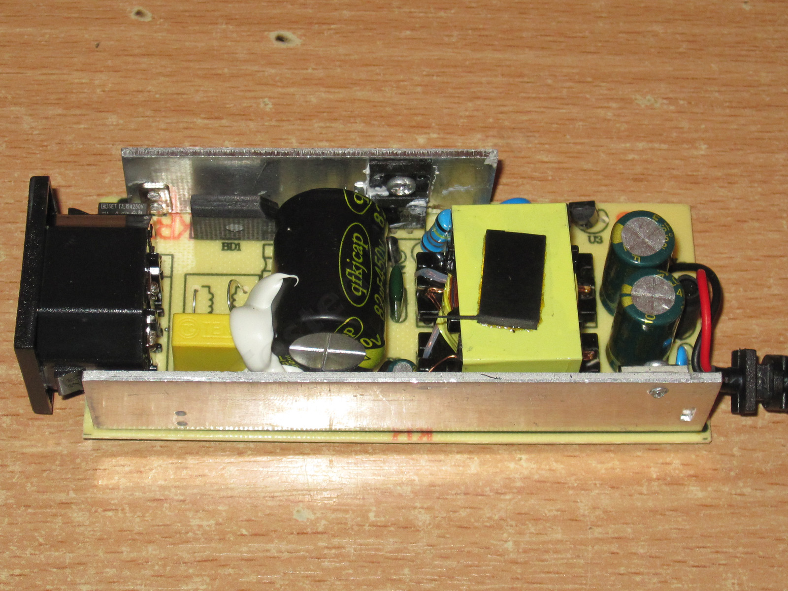
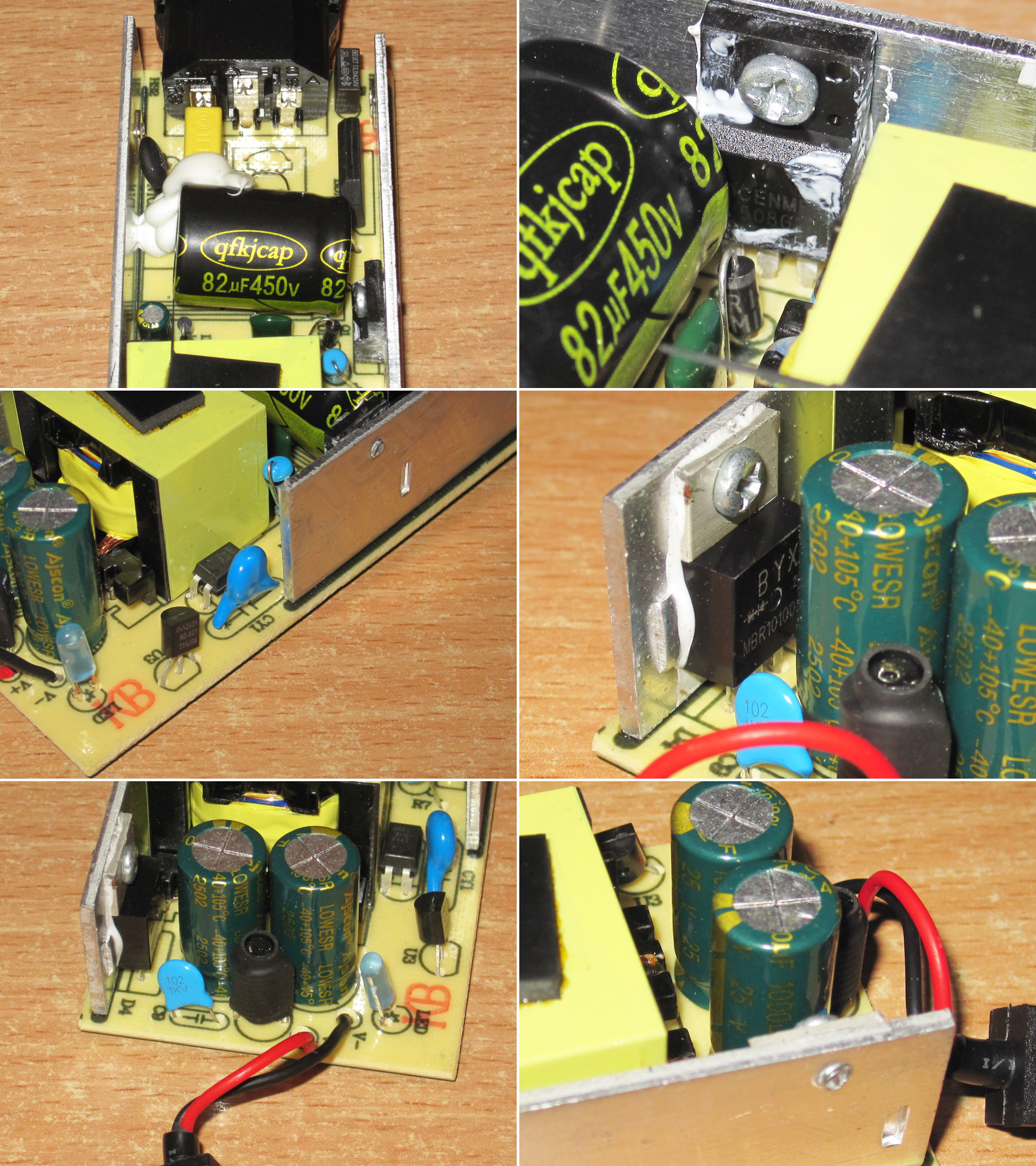
The input capacitor is rated at 82 µF, 450 V. For improved reliability, there is a 5 A, 650 V transistor, a Y capacitor, a 10 A diode assembly, 1000 µF, 25 V output capacitors (as we required), and here we finally have a proper output inductor.
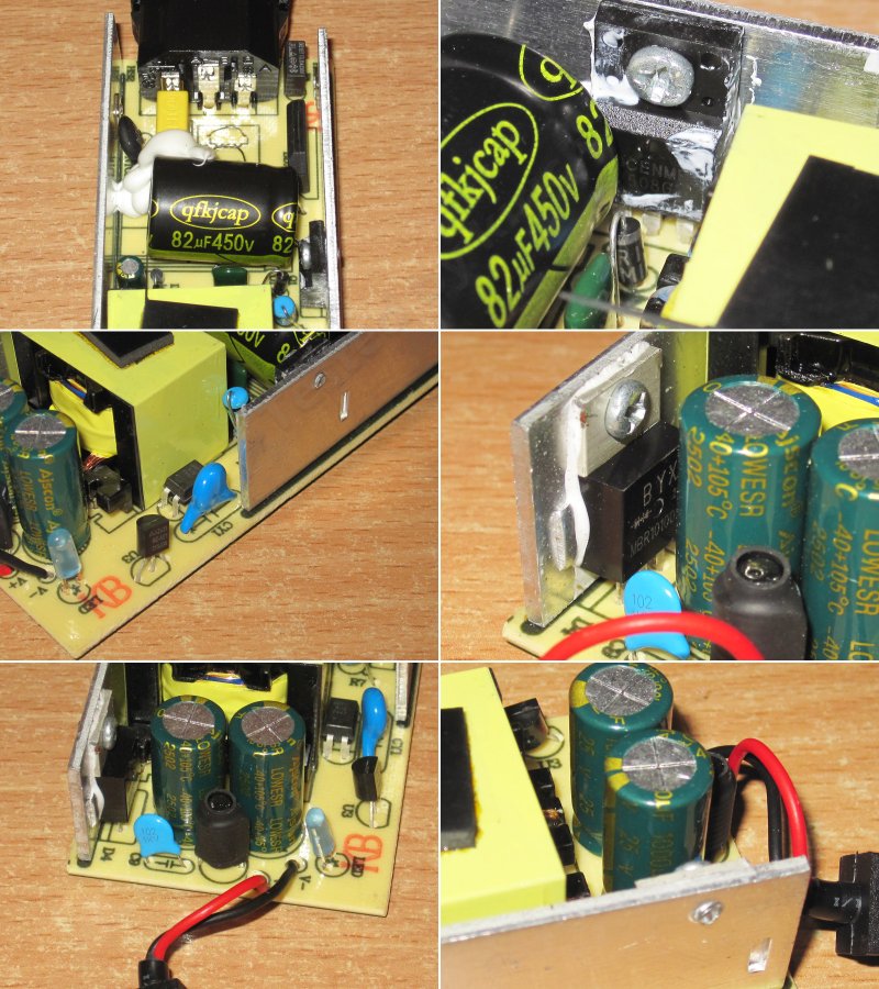
The board also looks neat.
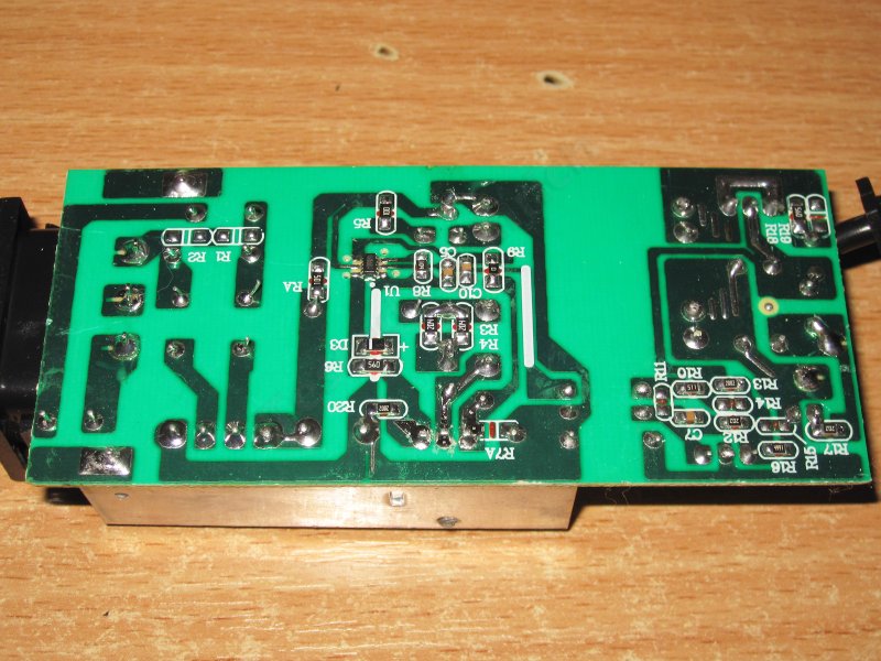
Unfortunately, there is also one safety weak point. We wrote to the manufacturer about it and will keep following up until they fix it.
The issue is that the copper pad where the heatsink-retaining pin is soldered is close to a trace that can be at either neutral or live mains potential.
I recommended improving safety by replacing the output diode assembly with the same type in an insulated package, or moving the traces so this area is safer. We'll try pressing the manufacturer again.

The input capacitor's actual capacitance is 75 µF, and the output capacitors total about 2100 µF, which is quite enough for 230 V and, in principle, for 115 V as well.

The protection trips at about 4.9 A when the power supply is cold and 4.7 A when hot. So we left a little headroom, but didn't go overboard.
With no load, the output is 12.45 V and power consumption is 0.45 W. Across a load-current range of 0.5–4.5 A, the voltage drops from 12.45 to 12.40 V at the board terminals.

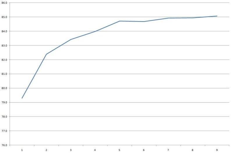
Efficiency is about 83–85% across the 0.5–4.5 A range; the scale below is in 0.5 A increments.
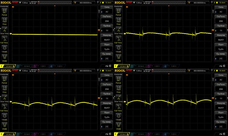
Ripple with no load and at currents of 1.5, 3, and 4.5 A.
Even at 10% overload, ripple is about 15 mV, and just 40 mV including the spikes. Nothing to complain about here.
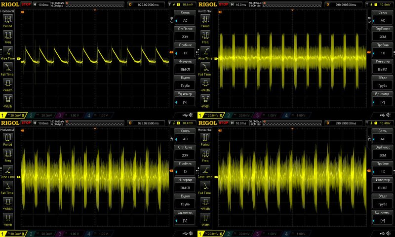
At 100 Hz, the waveform looks a little odd. The ripple amplitude itself is small, no more than 100 mV, but its shape is hard to explain. I showed something similar above, but this power supply is clearly fine: both the input capacitance and the output filter are adequate.
Still, given the small amplitude, you can simply ignore it.
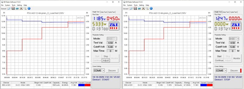
The thermal test was run at 2, 3, 4, and 4.5 A. The voltage varies by just 10 mV with temperature, which is within the measurement error.
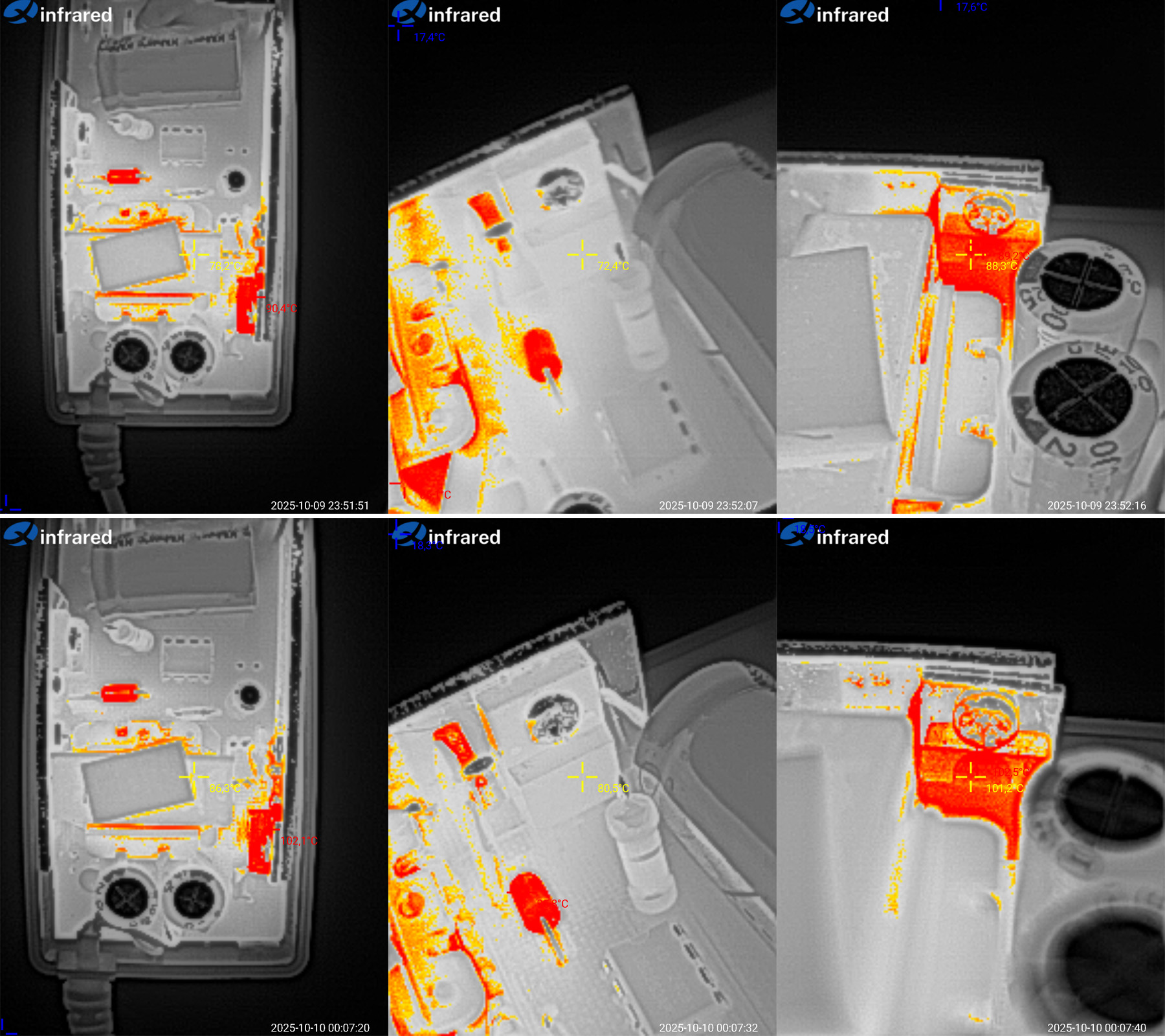
Now for component temperatures at 4 and 4.5 A.
At 4 A: transformer, 86 °C—excellent; transistor, 92.5 °C—perfectly fine; diode assembly, 102 °C—not exactly low, but still with plenty of headroom.
At 4.5 A: transformer, 93 °C—excellent; transistor, 104 °C—acceptable; diode assembly, 111 °C—rather high, but there is still a little headroom.
As with the previous unit, the protection current was set so the power supply would be difficult to overheat. In other words, it runs reliably at 4.5 A (more than 10% overload), but if you increase the current further, it trips into protection. And of course, the power supply delivers the claimed 4 A without any problems.
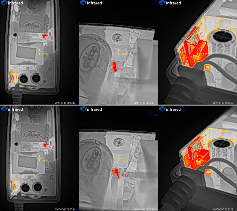
And now, a quick summary of all the models.
1203 - This would be a decent power supply if not for its wildly excessive overcurrent protection threshold: 5.7 A instead of the claimed 3 A. I think it could be made viable with a few adjustments.
1204 - The protection current is fine, as are the temperature and safety, but the ripple is a little high. I think it could be tuned up and would make a decent power supply too.
1205 - In practice, its specs are very close to the previous model, perhaps a touch more powerful, so there isn't much point in choosing it. It may be easier to tune up than the previous one, but this would then be a model rated for a real 4 A.
1206 - A rather disappointing unit, especially because of the excessive heat. Formally, this is a real 3 A power supply. There's no point in modifying it; it's more trouble than it's worth.
1207 - The ripple is somewhat high. I think it can be improved, but given the heat, this is a real 5 A power supply, or thereabouts.
1208 - If it were relabeled as a 1206, it would be a fairly decent power supply, provided the manufacturer doesn't decide to use no-name output capacitors instead of quality ones.
АД-12-1А - The output diode overheats at maximum load. Apart from the lack of an input filter, that's the only issue. Perhaps this will be addressed in future revisions.
АД-12-2А - Essentially the same as the previous model: the output diode gets too hot at maximum current. Add a second diode and that problem goes away too.
АД-12-3А - The only concern is safety. Otherwise, this power supply can actually run continuously at a higher power than its rating, and since the output capacitors are rated for 25 V rather than 16 V, it will probably last a long time too.
АД-12-4А - The conclusions are exactly the same as for the previous model: a good unit with plenty of power headroom, but with some safety concerns.
If you've read the article carefully, you've probably noticed that I mention safety quite often. The point is that this has absolutely nothing to do with a power supply's performance. In other words, you can have a power supply that produces ripple and gets hot as an oven, yet is completely safe—and vice versa: excellent power delivery, but not so safe.
But the point is, consider this my personal "quirk." I've encountered similar safety issues many times, even in quite reputable products sold in large quantities, with nobody complaining. Personally, though, I consider this important (under certain operating conditions), and I'll always strive to make a device not only high-quality but safe as well. So if, following our recommendations to the factory, we get an inexpensive, reliable power supply with good performance, the next step will be to make it as safe as possible too. Unfortunately, we can't do everything at once. If you don't understand why, try talking not just to a seller on AliExpress, but to the manufacturer. You'll see: a batch of 1,000 units is practically a retail order, and it's hard to find a competent engineer there.
That's all for now. I really hope this was useful, and thanks again to Vitaly for providing the samples.
A reminder: to keep up with new posts on the blog, I recommend following me on Instagram. I’ll post notifications about every new article there, and might also write about something interesting from time to time — link to my account
You can also subscribe to updates and new articles on the Telegram channel — https://t.me/KirichBlog
A package arrived with ten different power supplies. I’ll say right away that, in my opinion, a plastic enclosure is far from the best choice for a power supply. The problem is that heat dissipation is much worse in enclosures like these. Still, it’s the simplest way to make a complete, ready-to-use device.
You’ll probably say, “What about laptop power supplies and the like?” Yes, fair enough, but those are a very different story. First, the components and circuit design are more sophisticated, so efficiency is much higher. But the main difference is the layout: potting the board with sealant or compound removes the air, so heat is transferred to the plastic enclosure almost immediately (and sometimes literally right away). The plastic can also have fairly good thermal conductivity. In cheap, no-name Chinese models, the components first heat the air, which then warms the enclosure through natural convection. The result is a relatively warm enclosure and hot electronics. Laptop-style power supplies may feel as hot as a stove, but that’s because the components transfer heat efficiently, so their actual temperature isn’t as high.
Obviously, Chinese factories churning out the cheapest possible models aren’t going to bother with this: it’s complicated and expensive. So we get what we get.
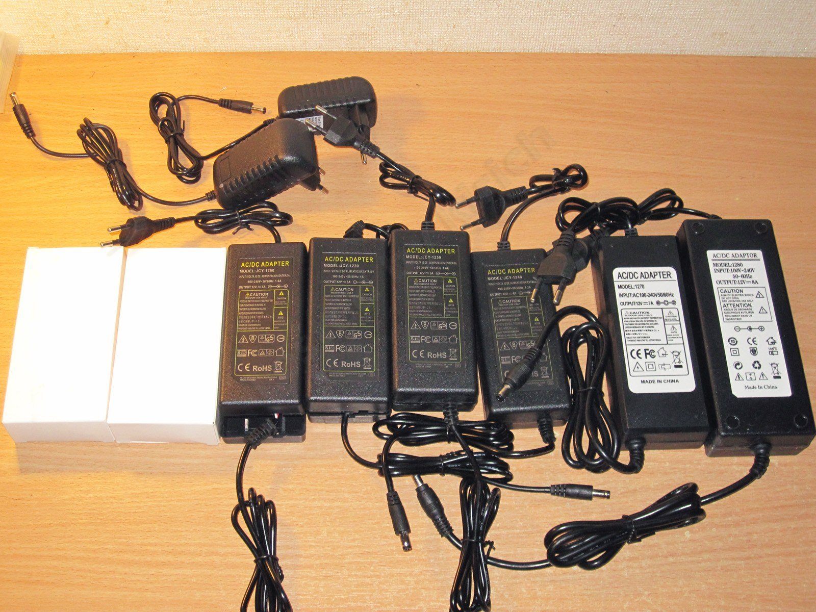
As I said, the power supplies are split into two groups: six and four. I’ll start with the six models sent as samples. Four of them look identical.

All the power supplies are rated for 12 V, with claimed output currents of 3, 4, 5, 6, 7, and 8 A, and are marked 1203–1208, respectively.
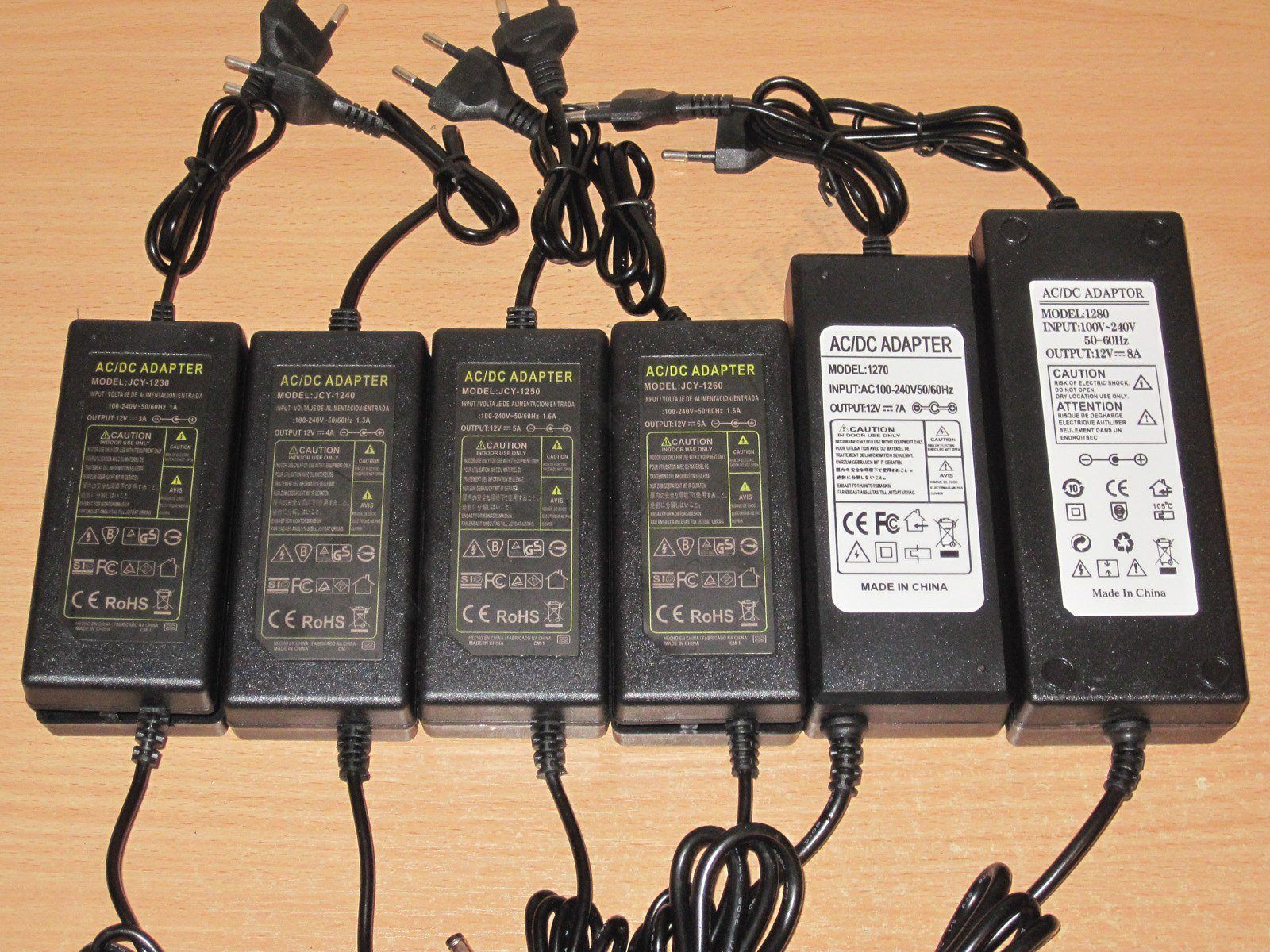
As usual, I’ll go in ascending order, starting with model 1203 and ending with 1208.
First up is the 12 V, 3 A power supply. Inside, it’s empty and sad.

Here’s a Lenovo laptop power supply as an example. It’s rated at around 45 W, and you can see that the heatsinks are positioned to minimize the air gap. This costs nothing—or almost nothing—to do in production; you just have to think about it a little. The same goes for the transformer: you can transfer heat to the enclosure in the same way, either directly through a thermal pad or by adding a heat spreader. And I haven’t even mentioned designs where part of the heatsink sits directly in the plastic enclosure, as in some Mean Well models.
All these tests are making me increasingly keen to design my own budget power supply and then place an order with the same factory that makes the cheap ones.
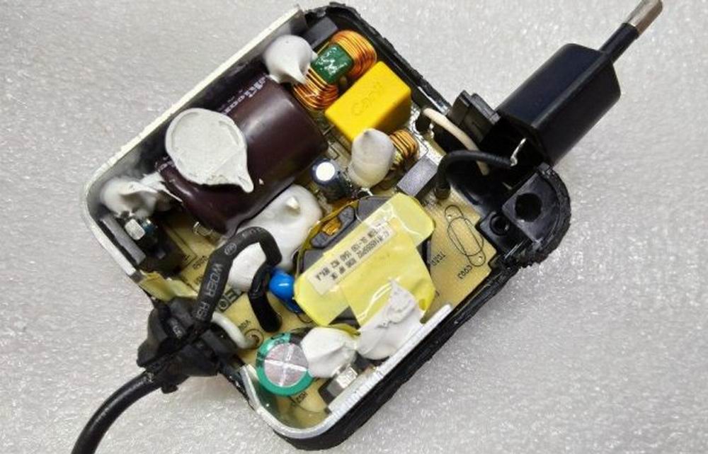
I noticed something interesting during the initial inspection: the opening for the LED in the enclosure is designed to work either way, so it’s easy for the factory to put it on the left or the right.

There’s no input filter; the design is as simple as it gets. At least they didn’t forget the fuse.
The input capacitor is marked 47 µF, the transistor is rated for 5 A, and there’s a Y capacitor. On the output, there are two diodes and two capacitors rated at 16 V: 680 + 1000 µF.

No complaints about electrical safety, or the circuit board, for that matter. The assembly is even reasonably neat, apart from the usual Chinese habit of soldering wires directly to the traces instead of through the holes.

The input capacitor’s actual capacitance is 30 µF, and the output capacitors add up to 1650 µF. It’s clear that the input capacitor should have been marked 33, but they decided to make it look “nicer.” Still, 30 µF is enough for a 230 V mains supply and 36 W output power.

The overcurrent protection trips at a much higher current than it should: although the rated current is 3 A, it doesn’t kick in until 5.7 A, which is far too high. The trip current doesn’t depend on temperature.
The output voltage measured at the power supply terminals is 12.28 V with no load, and varies from 12.28 to 12.25 V over the 0.5–4 A range, which indicates good regulation. Everything else you see on the graph is due to the voltage drop across the thin output cable.
No-load power consumption is about 0.45 W.

Efficiency is around 85%, which is fine for budget models. Efficiency was measured from 0.5 to 4 A in 0.5 A increments.
As usual, I measured high-frequency ripple with no load and at 33%, 66% and 100% load. At maximum current, the main ripple component is around 200 mV, which is quite acceptable for models like this.
There are no issues with 100 Hz ripple either, so we can consider this test passed.
I tested it at 1, 2, 3 and 3.2 A; the last step was just out of curiosity. The output voltage has a slight negative temperature coefficient: when hot, the unit's output is 40 mV lower than when cold.

Temperature rise at load currents of 3 and 3.2 A. Here, I'd even say everything looks fine: the transistor is ideal, and the transformer does pretty well too. The output diodes get fairly hot, but if you keep the current below 2.5 A, it should work without problems. The one thing that definitely needs changing is the protection current setting.
The 1204 is a 12 V, 4 A unit. Essentially, it's not much different: they added a heatsink to the output diode assembly and moved the transistor heatsink to the side.
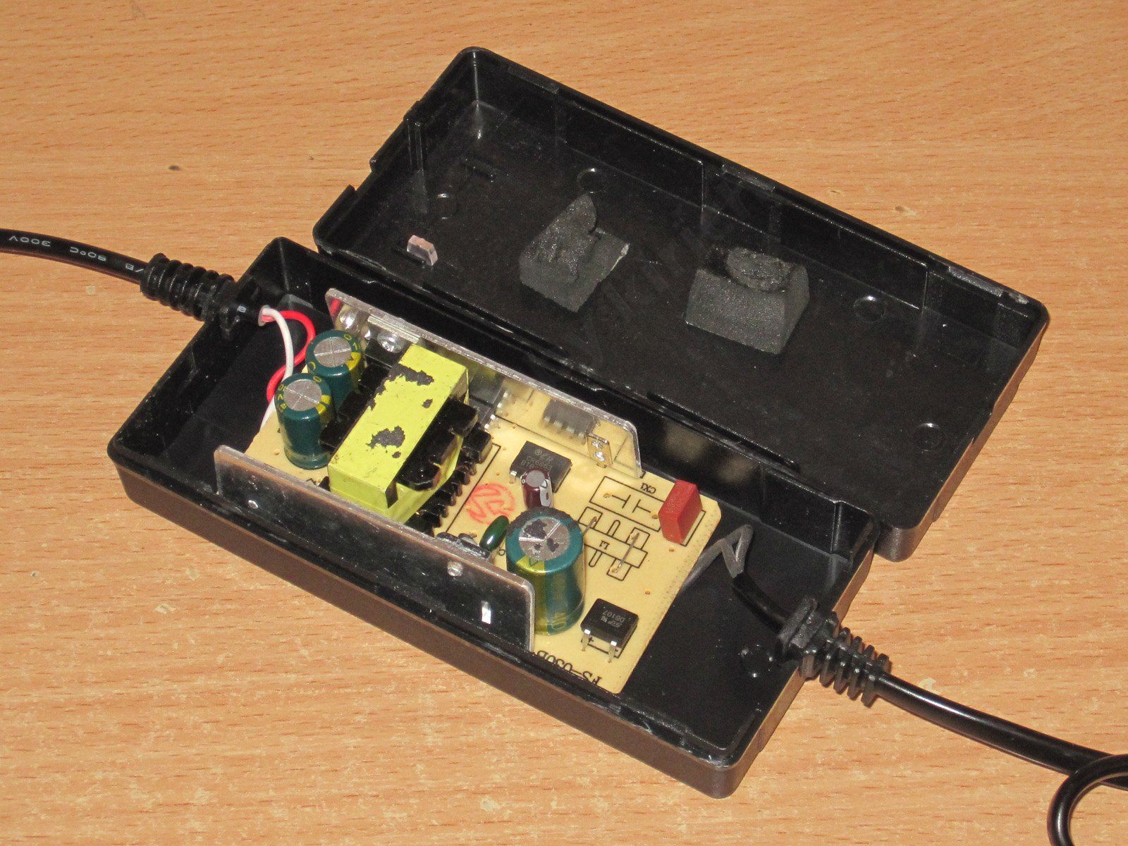
There's no filter here either. I should say that the lack of a filter isn't always critical, but a thermistor would definitely help, since it limits the inrush current while the input capacitor charges. The larger the capacitor, the more important it is to have a thermistor.
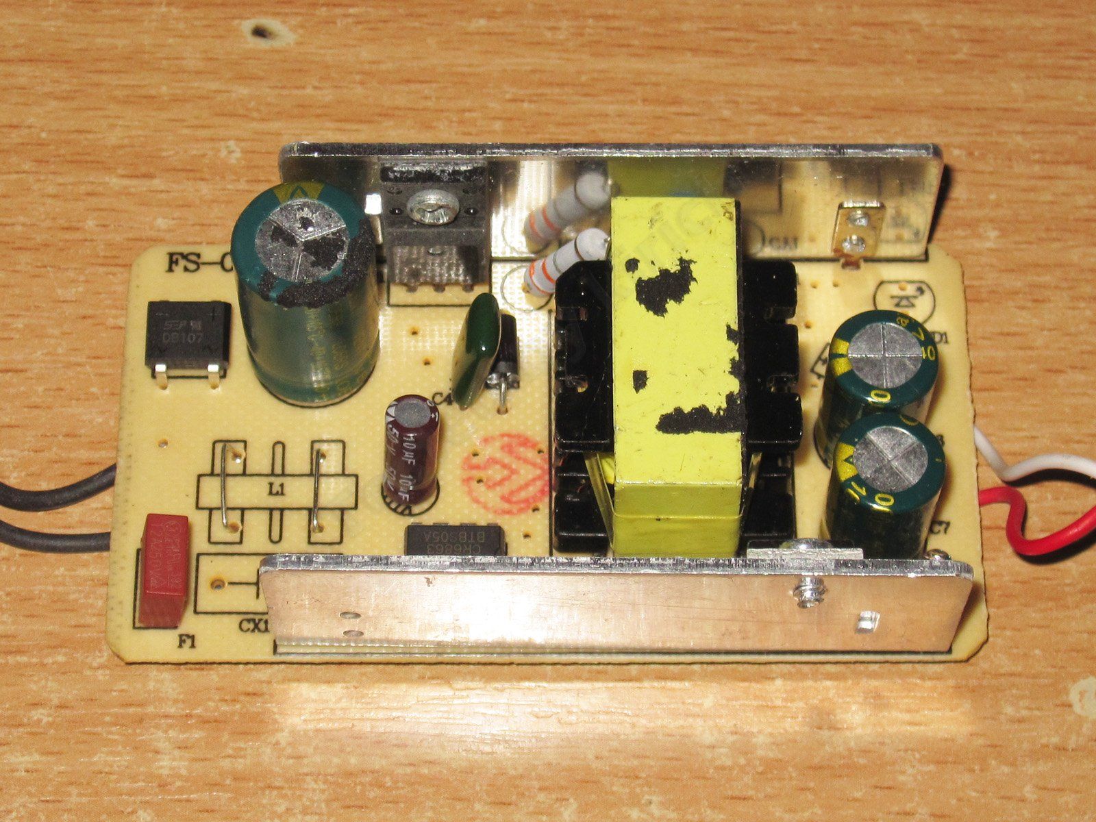
The input has only a fuse. The capacitor is marked 47 µF, just like in the previous version. The transistor is rated for 7 A, and there's a Y capacitor. On the output, there's a 20 A diode assembly and a pair of 16 V, 1000 µF capacitors.

From an electrical safety standpoint, the board has two critical points: the heatsink mounting points. The upper heatsink is connected to the output because the diode assembly isn't insulated. The transistor is in an insulated package, but its heatsink is connected to the negative side of the high-voltage input.
The only way to fix this is to change the PCB routing and the location of the heatsink mounting contact.
The input capacitor is 30 µF, just like in the previous version. The output capacitors are fine: 1000 + 1000 µF.
The protection trips at 5.2 A, which is quite acceptable. With no load, the output is 12.37 V, and the unit draws 0.45 W, just like the previous one.
As the load current increases from 0.5 to 5 A, the voltage at the board terminals drops from 12.37 to 12.33 V, which is excellent.

Efficiency is around 86%, measured from 0.5 to 5 A in 0.5 A increments.
High-frequency ripple with no load and at currents of 1, 2 and 4 A.
This is worse than the previous unit: at 4 A, we get around 300–350 mV, not counting the spikes. It's not a complete disaster, but I'd like to see better results, and I wouldn't use it with sensitive loads.
No complaints at 100 Hz.
I checked the temperature rise at 2, 3 and 4 A. The output voltage is practically unaffected by temperature: it was 12.39 V and stayed at 12.39 V.
Temperatures at 3 and 4 A.
I have to say, things look more or less good here:
At 3 A, the transformer is at 79°C—excellent; the transistor is at 75°C, also good; and the diode assembly is at 87°C, which is fine.
At 4 A, the transformer is at 94°C, which is acceptable; the transistor is at 92°C, also no complaints; and the diode assembly is at 107°C. That's not too high, but there's not much headroom.
Personally, I wouldn't run it continuously above 3–3.5 A. At that load, it should last a good long time, although at room temperature it handles 4 A just fine.
The third unit under test is the 1205 model, rated at 12 V, 5 A.
Essentially, this is a slightly modified version of the previous one.
The visible changes are a larger bridge rectifier, a higher-capacitance capacitor, and slightly beefier heatsinks.
The input capacitor is marked 68 µF. The transistor is rated for the same 7 A as the one in the previous unit. There is a Y capacitor, hidden between the transformer and the heatsink. On the output, there are two 1000 µF, 16 V capacitors. The diode assembly marking is hard to read; I think it's 20 A.
One interesting thing: it has two LEDs, a main one and a backup :))))

The board is pretty typical for this kind of power supply. As for safety concerns, the diode heatsink mounting point is close to a hot-side trace, but since the diode assembly is in an insulated package, it's not that critical.
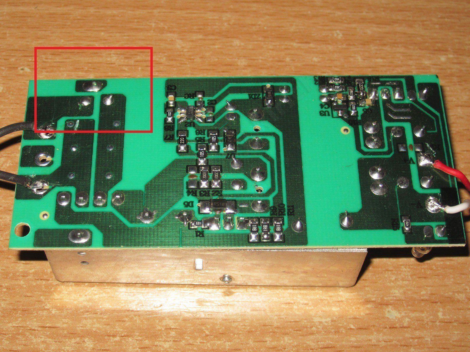
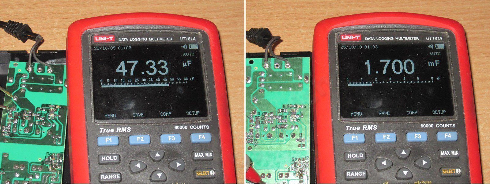
The input capacitor has an actual capacitance of 47 µF, exactly one step down in the E6 series. The output capacitors add up to 1700 µF, which is odd; usually there are no complaints about them.
The protection is set to about 5.5 A. Once the current limit is exceeded, the output voltage starts to drop rather than shutting off completely.
When the unit is warmed up, it trips a little earlier.
The no-load voltage is 12.22 V, and power consumption is 0.35 W. With a load current of 0.55 A, the voltage at the board terminals drops from 12.22 to 12.04 V, which is acceptable.

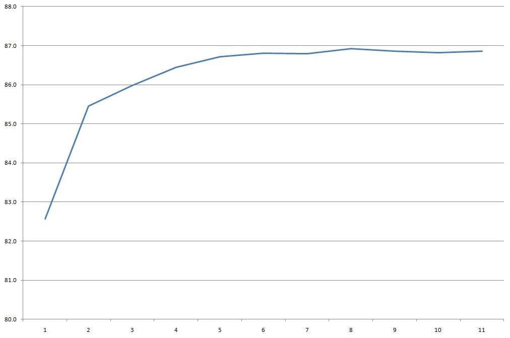
Efficiency is almost 87%, which is pretty good for a budget power supply. Efficiency was measured from 0.5 to 5.4 A in 0.5 A increments.
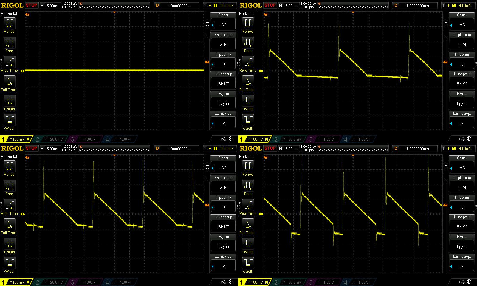
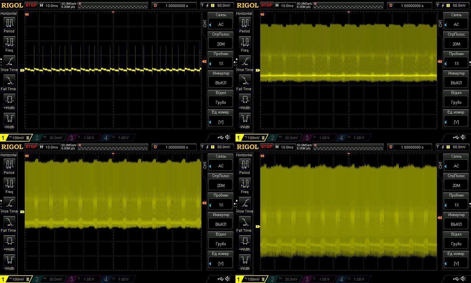
Ripple at no load and at currents of 1.5, 3, and 5 A.
The high-frequency ripple is acceptable, around 250–300 mV at maximum current, but there are some very large spikes. They aren't too critical for the load, but they do make life hard for the capacitors.
Everything looks fine at 100 Hz, but since the input capacitor is just barely large enough, I think things will look noticeably worse at 115 V.
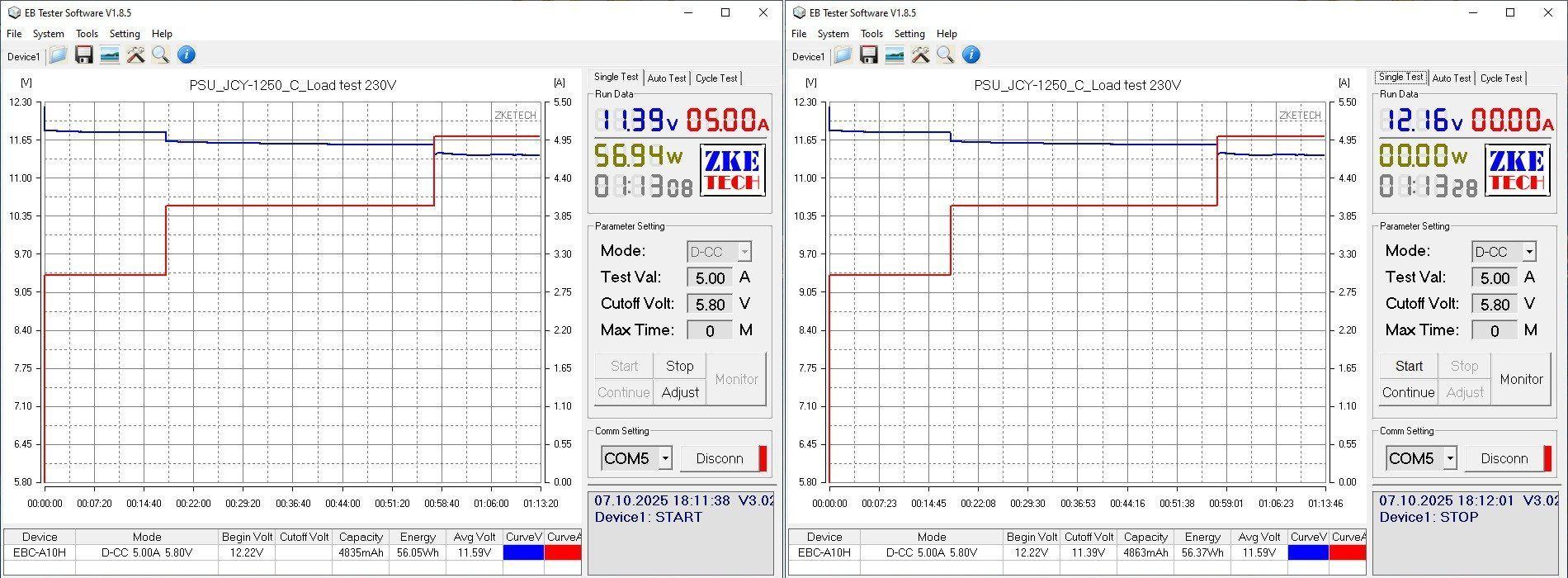
I checked the temperature rise at 3, 4, and 5 A. The output voltage has a small negative temperature coefficient, about 60 mV, which is perfectly fine.
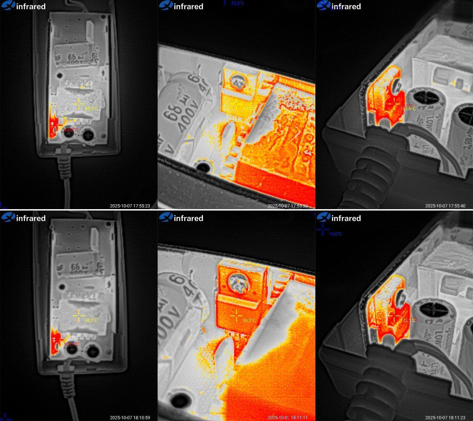
Temperature rise at 4 and 5 A.
At 4 A, the transformer reaches 89 °C, which is fine; the transistor reaches 85 °C, also fine; and the diode assembly reaches 107 °C, a bit high but tolerable.
At 5 A, things are of course worse. Efficiency is almost the same as with the previous unit, and the enclosure is the same size, but the power is higher. As a result, the transformer reaches 98 °C, right on the limit; the transistor reaches 96 °C, a bit high but tolerable; and the diode assembly reaches 125 °C.
In my opinion, this power supply's continuous current rating is no more than 4 A, and possibly less. Essentially, it's about the same as the previous one.
Model 1206, the most powerful one in this enclosure size: 12 V, 6 A.
Now that's progress—they added an X capacitor :) But really, it's essentially the same design shown above, with a few minor tweaks.
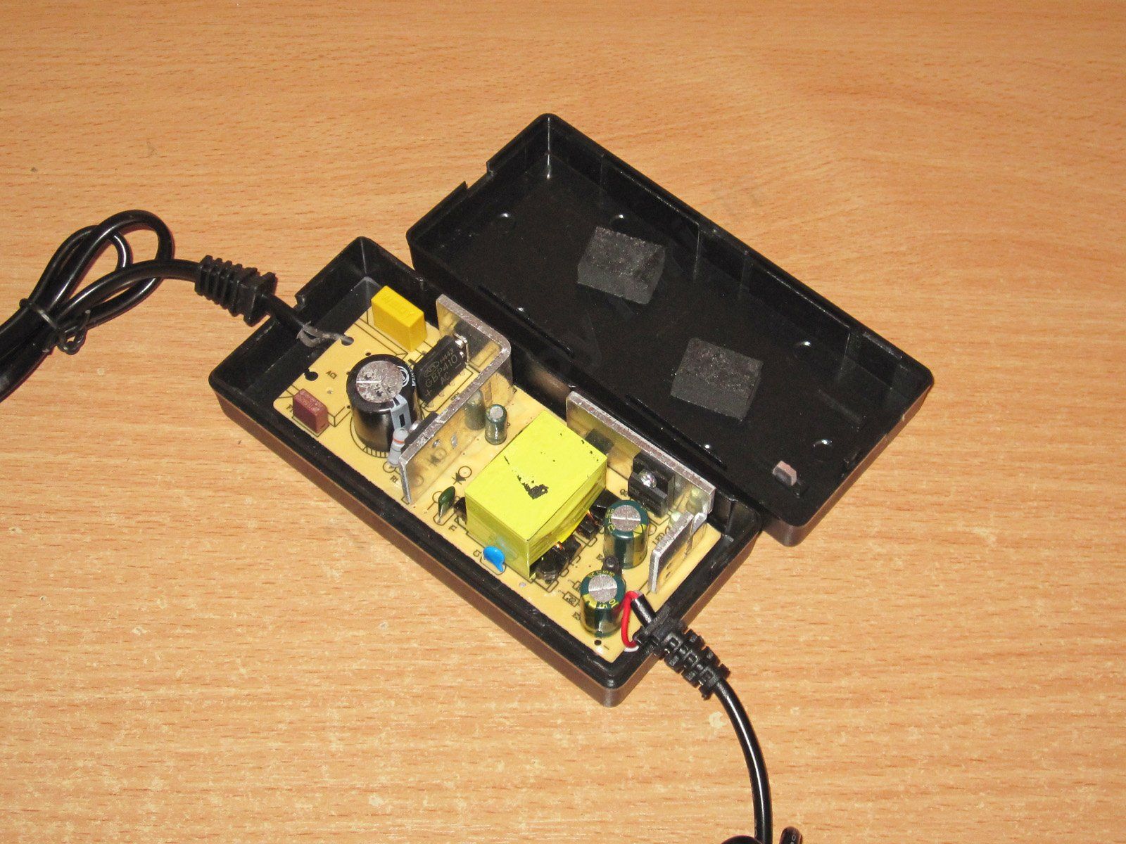
They used two L-shaped heatsinks instead of straight ones that run across the entire board. It's not a bad solution, though I've more often seen U-shaped heatsinks in power supplies like this, which are even better. The transformer looks pretty good; I can easily believe it’s rated for 60–70 W.
The input capacitor is 47 µF, clearly too little for the claimed power. It might just about be enough at 230 V, but there will be problems at 115 V.
The transistor is rated for 5 A and 65 V. Odd—the only one of the models shown above with this transistor was the 3 A version; the others use 7 A parts.
They used a regular high-voltage capacitor instead of a Y capacitor. The markings aren’t visible, but I can tell that anyway.
The output diode assembly is rated for 20 A and 100 V, which is fine overall.
The output capacitors are 1000 µF, 25 V. Unusual—16 V parts are more common. Nice.
Even nicer, there’s an output inductor to reduce ripple.

The underside is generally neat, though it’s disappointing that, as everywhere else, the wires are soldered to pads on the board rather than through holes. The wires are thin, too, especially the mains wires.

The input capacitor’s actual capacitance is 44 µF, so the marking is accurate. The output capacitance is fine too: we get 2000 µF.

The protection trips at around 7 A. That’s tolerable for a 6 A power supply, though something tells me it won’t deliver 7 A for long.
The no-load voltage is 12.33 V, and power consumption is 0.55 W. Under a load in the 0.5–6.5 A range, the voltage varies from 12.33 to 12.26 V, which is basically fine. But because of the thin wires at the connector, the voltage drop takes it from 12.33 down to 11.36 V.
With the previous models, efficiency increased slightly as power went up. Here, though, it’s only 85%—rather low compared with the others.
Efficiency was measured from 0.5 to 6.5 A in 0.5 A increments.
As expected, high-frequency ripple is low. Measurements were taken with no load and at currents of 2, 4, and 6 A.
At 6 A, the main ripple is around 40 mV. There are short spikes, but they’re small too.

But at 100 Hz, things look unpleasant. The overall ripple seems similar to the previous models, around 350 mV, but it feels as if there’s no input capacitor at all—even though we measured its capacitance above. I later measured the ESR too and found nothing alarming, but the behavior is strange.

I should also note that when measuring high-frequency ripple, the waveform usually looked something like this. The fact that it looks almost normal above is more of a fluke.
The thermal test was conducted at.... at one current value; the plan was to test at 4, 5, and 6 A, but the very first test changed everything.
Incidentally, the voltage barely depends on temperature.
I stopped the test at 4 A for a reason: even at that current, overheating became apparent. After that, I didn't increase the current, but ran it in the same mode for a while longer.
After a total of 45 minutes, the results were as follows (bottom photos): transformer at 97°C—not great; transistor at 101°C, also pretty high; and the diode assembly above 133°C. The thermal camera was off the scale—clearly too much.

While inspecting the previous models, I noticed that none of them had thermal paste. So, as an experiment, I decided to fix that here, hoping it would bring down the diode assembly's temperature.
After that, I ran the power supply for about another hour.
At the same 4 A (the power supply was already slightly warm when I started), I got 105°C for the transformer, 113°C for the transistor, and over 133°C for the diode assembly.
The power supply overheating is a fact. What's less clear is why this one overheats at 4 A, while the previous models ran cooler at the same current—or at least no hotter.
All in all, it seems decent in some respects, but the severe overheating ruins the whole picture. This power supply can't even handle 4 A, let alone 6 or 7.
The fifth power supply is model 1207, rated at 12 V, 7 A.
The case is a little larger, but the board inside is just as bare. By the way, I forgot to mention this about the previous one: the board was originally designed for an AC inlet, and personally I prefer that arrangement. But the manufacturer ended up soldering in a mains cable instead, and a rather thin one at that.
It really feels like they left out some parts :)
The input capacitor is 68 µF, and the transistor is rated for 10 A—not bad.
The diode assembly is rated for 30 A, and the output capacitors are 1500 µF, 16 V—also better than the previous models. The output capacitors are Aishi, too.
There is a Y capacitor; it's just not visible.

At first I thought the circuit board was like one of the previous versions, where I complained that one of the heatsinks was connected to the high-voltage section. But no: at first glance the clearances look very tight, but the transistor has an insulated case, so there's no major danger. The diode assembly heatsink's mounting point is also a good distance from the high-voltage section.
The input capacitor's actual capacitance is about 61 µF, while the output capacitance is closer to 3250 µF—more than specified.
The input capacitor's capacitance makes me suspect it's used and has already lost some capacity, since 61 is outside the tolerance for the specified 68. But I can't say for sure, although used components are common in power supplies like these. It's just enough for our mains voltage, though a close call; it would be too little for 115 V.

They installed two LEDs here as well, with one of them off to the side of the board instead of in its designated hole. The whole thing is a bit ridiculous: there are holes for the wires, so they solder them to the underside of the board; there's a designated spot for the LED, so they solder it on the side...
And yes, here's a clear example of redundancy: only one of the two LEDs works—and it's the one that isn't opposite the hole :)))

The overcurrent protection is set to about 6.8–6.9 A. When hot, the limit is even lower, around 6.5 A, so it will trip before reaching the specified 7 A. Maybe that's for the best.
With no load, the output is 12.67 V, while power consumption is a hefty 1.55 W. I suspect that's down to the use of an ancient PWM controller.
I'll also blame that PWM controller for the strange fluctuations in voltage as the load current changes. The issue isn't that the voltage drops from 12.67 to 12.51 V as the load current goes from 0.5 to 6.5 A—that's perfectly normal. It's that the drop happens in waves.
Even so, the power supply managed an efficiency just over 86%, although performance at low loads isn't great. And it's best not to run it with no load because of its high power consumption.
Efficiency was measured from 0.5 to 7 A in 0.5 A increments. At 7 A, the output voltage was 12.12 V.
Ripple was measured with no load and at 2, 4, and 7 A. The results aren't great, in my opinion: even at 4 A, it's around 300 mV, and at 7 A it's almost 400 mV. As I wrote, these are perfectly fine for various lighting applications, and they’ll also do for powering small motors. But if you have anything sensitive, it’s better not to use them.

At 100 Hz, ripple only becomes noticeable at maximum power; otherwise, it’s perfectly acceptable.

I checked the temperature rise at currents of 4, 5, and 6 A. The output voltage does vary with temperature, but only very slightly.

Test results at 5 and 6 A.
At 5 A: transformer, 83 degrees—fine; transistor, 70—also fine; diode assembly, 98—which is a bit much considering the current is only 5 A and the rating is 7 A.
At 6 A: transformer, 105—overheating; transistor, 92—fine; diode assembly, 115—a bit much, but tolerable.
Based on the measurements, this power supply is basically decent, but its working current is only around 5 A; above that, it will overheat.

And now the most powerful model in this lineup, the 1208, rated for 12 V at 8 A.
This one has a larger case, though it’s still half empty. And wow, they even added an input inductor. But, like all the previous models, it has no thermistor—and this one could definitely use one.

The layout is typical and doesn’t differ much from the previous models.

Yes, there’s an inductor and a capacitor, but oddly, they used discrete diodes instead of a proper high-power module. In short, cost-cutting.
The input capacitor is 82 µF, rated for 450 V—unusual. There’s no marking on the transistor at all, and it looks like it wasn’t rubbed off; it was never printed in the first place....
On the output side, there are two 20 A diode assemblies and three 1000 µF, 16 V capacitors. They’re branded, though I have my doubts that they’re new.
And yes, two LEDs again. What, did a truck full of LEDs overturn near the factory?

I have no major complaints about the circuit board layout; everything is relatively safe.
The input capacitor measures 75 µF versus the stated 82, but let’s put that down to measurement error. The output capacitance is noticeably higher than the expected 3000 µF, so it’s quite possible that the capacitors, even if not new, are at least in good condition.

And here are a couple of issues.
First, I noticed that the leftover piece of foam rubber that holds the board in the case doesn’t line up with where the rubber pad itself is installed.
Look closely and you can see adhesive residue on the input capacitor, while the rubber pad on the case is clearly farther to the right and couldn’t possibly have left that mark. So the capacitor is clearly used.
I also noticed that one of the output diode assemblies is clamped at an angle. It’s simply pressed against a protruding stop, with only the edge of its flange held down. We’ll see how it works, but I can already say that even if everything works fine, this kind of deformation could have cracked the case, and components like this shouldn’t be used.

The protection current is set quite high: 10 and 9.8 A, practically right up against the maximum load current of 10 A. I was already starting to worry that I’d have to get another one out.
With no load, the voltage is 12.37 V and the power is 1.7 W. As the load current varies from 0.5 to 9.5 A, the voltage at the board’s own terminals drops from 12.37 to 12.06 V, which is quite significant. As with the previous model, you can also see the voltage fluctuating in waves. Generally, I hadn't paid much attention to these waveforms before, but in fact they're a characteristic of the PWM controller used, as is the high power consumption with no load. 1.7 W really is a lot.
Even so, efficiency is around 86%, though it's clearly lower at the very lightest load because of the unit's own power consumption..
As for ripple, I'd say it's actually pretty good. I checked with no load and at 3, 6, and 8 A. At the maximum current, ripple was around 100–120 mV. Since there's no filter here, that's clearly thanks to the good capacitors.
At 100 Hz, it also looks fine.
I checked the temperatures at 4, 5, 6, and 7 A. I forgot to take a screenshot after removing the load, sorry.

Test results at 6 and 7 A.
At 6 A: transformer, 96°C—rather hot; transistor, 76°C—fine; diode assemblies, 105–107°C. Interestingly, the one that's clamped crooked is cooler. Maybe that was intentional?
At 7 A: transformer, 115°C—severely overheated; transistor, 95°C—acceptable; diode assemblies, 125°C and 126°C—too hot. I wouldn't push it any harder.
So, for this power supply, I'd say its actual output current is no more than 6 A. It can deliver more for a short time, but I wouldn't recommend it. The protection isn't set up very safely either, so it's easy to kill the unit by overheating it.

Now for the power supplies I've already had in for review and that have had some changes made to them, mostly to the components and their ratings.
There are four models here, all 12 V, rated for 1, 2, 3, and 4 A.
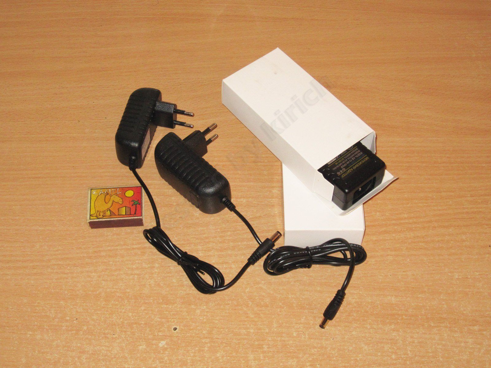
Two are plug-in wall adapters, while the other two use a standard power cord.
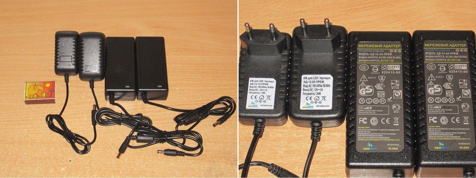
I'll start, of course, with the smallest one, AD-12-1A — price: 63 UAH — link
There's not much to it, though given the price, you probably shouldn't expect anything more. Still, what matters more are the specs and build quality.
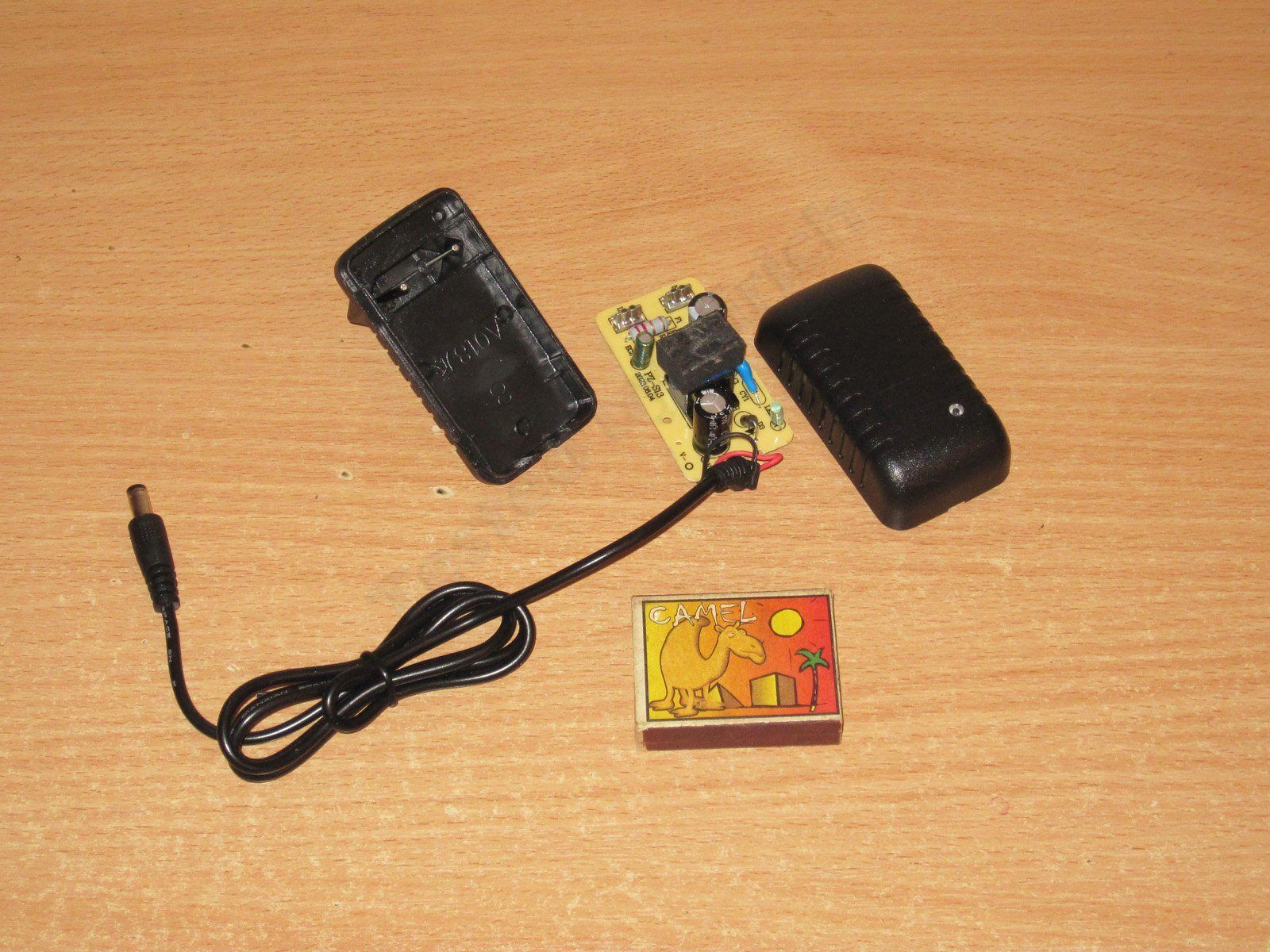
There's no fuse as such; its job is done by a fusible resistor, which also limits the inrush current.

The input capacitor is 15 µF, 420 V, which gives plenty of margin for the rated power and our mains voltage. I think it would also work at 115 V, though with a slight reduction in power.
There's a Y capacitor. The output diode is a bit undersized, though I'll get to that later.
The output capacitor is 470 µF, 25 V. As with the other models, the wires are soldered to the underside of the board :(
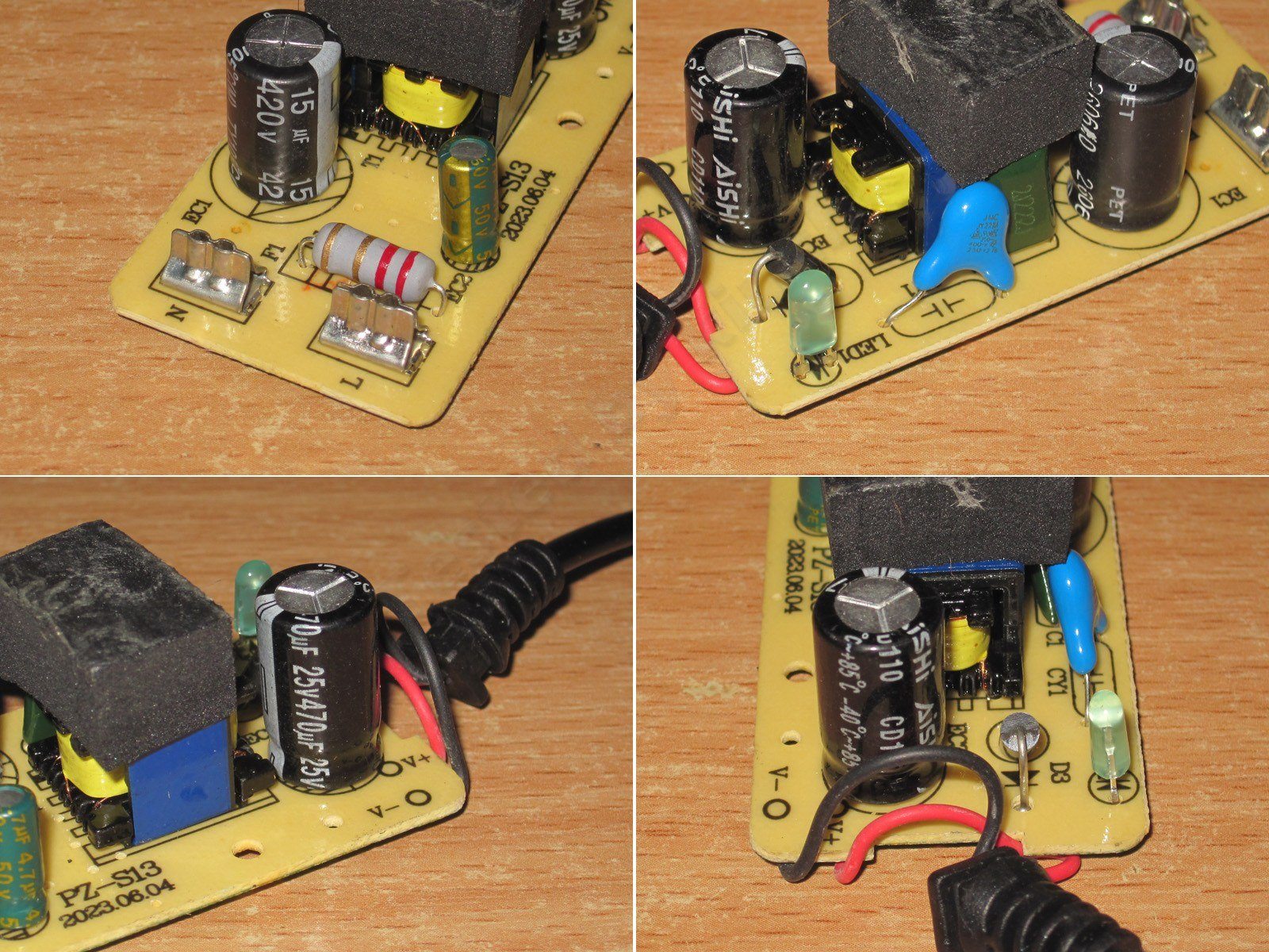
I have no concerns about electrical safety. I would point out two things, though. First, there's no feedback optocoupler, so we'll check the voltage regulation accuracy later. Second, it uses an integrated PWM controller. I consider a PWM controller with a built-in high-voltage transistor an advantage, since it also has a thermal sensor, so I have no concerns about its protection.
For some reason, I couldn't get a reliable measurement of the output capacitor's capacitance with my multimeter, and I couldn't be bothered to get another instrument. The input capacitor's capacitance is essentially as specified.
The power supply goes into protection above 1 A. It handles 1 A without any problems, but the protection trips at 1.1 A. Yes, it's right on the limit, but maybe that's a good thing.
With no load, the output voltage is 12.12 V and power consumption is 0.4 W. As the load increases from 0.2 to 1 A, the voltage changes from 12.12 to 12.43 V. The power supply does have some compensation for voltage drop in the wires (probably parasitic), although the graph clearly shows when it suddenly raises the voltage.
Overall, I have no complaints about its stability.

In my opinion, efficiency is low. I expected more, though the relatively large measurement error may also have affected the result. I measured from 0.2 to 1 A in 0.2 A increments.
Ripple was checked with no load and at 0.3, 0.6, and 1 A. At maximum power, I measured about 250 mV. That's a bit high for a power supply of this rating, but overall it's perfectly acceptable.
I have no complaints about the 100 Hz ripple; everything is as expected and within acceptable limits.

The thermal test was run at currents of 0.5 and 1 A, for about 30 and 40 minutes at each stage.
The output voltage rises with temperature by about 110 mV. I wouldn't call that critical, especially given the lack of proper feedback.

Below are three thermal images. The first shows the transformer at 0.5 A: just 62 degrees. The second and third were taken at 1 A: the transformer is at 94 degrees, which is fine; the output diode is at 130 degrees, which is too hot; and the PWM controller is at 70 degrees, which is excellent.
A couple of words about the diode. I wrote above that it's a bit undersized, and in the preliminary tests on the sample its temperature was slightly lower, otherwise I would have noticed. Here, I recommended either replacing it with a more powerful one or adding a second identical diode in parallel. The difference in cost would have been just 3–5 cents, since a 3 A diode costs us about 6 cents at wholesale.
That said, if the power supply is used at currents of 0.7–0.8 A, the diode that's already installed will be more than enough.
The second power supply, AD-12-2A, costs 93 UAH — link.
The case is a little larger, and there are some noticeable changes to the components as well.

A fusible resistor is used as the fuse here too, but there are two input capacitors and an inductor, forming a CLC filter.

The PWM controller is a more substantial one; these are often used in supplies rated around 24 W, so no concerns so far. This one also has optocoupler feedback.
The input capacitors are the same type as in the previous model, but there are two of them here, for a total of 30 µF, which is more than enough for 24 W.
There is a Y capacitor, and the output has a pair of 470 µF, 25 V capacitors to improve reliability.
The circuit board is neatly made, and I have no safety concerns either.

The actual input filter capacitance is almost 30 µF, and the output capacitance is 890 µF; both are within the measurement error.
The protection current is determined by the installed PWM controller and is about 3 A or 2.8 A, depending on how hot the power supply gets.
With no load, the output voltage is 12.29 V and the power consumption is 0.5 W. Output voltage stability at the board terminals is perfect: across a load range of 0.2 to 2.8 A, the voltage stayed between 12.28 and 12.29 V. Note that this was even with an overload of almost 50%.

The efficiency, however, isn't very high—about 76%. It could be better.
High-frequency ripple with no load and at currents of 1, 1.5, and 2 A.
At maximum power, we get about 250 mV. That's rather high, but still within the tolerance for budget power supplies. An inductor between the capacitors would improve things, but there isn't one here, and there's no room for one either.

No complaints about the low-frequency ripple; it's all as expected. The only odd thing is the waveform, which looks a bit like a picket fence.

The load test was run at currents of 1, 1.5, and 2 A. The output voltage rises with temperature, but by only 20 mV, so you can pretty much ignore it.

And now the temperatures of the main components. Below are photos taken after the tests at 1.5 and 2 A.
At 1.5 A: transformer, 81 degrees—excellent; PWM controller, 92 degrees—acceptable; output diode, 104 degrees—acceptable.
At 2 A: transformer, 101 degrees—hot, though there's a little headroom; PWM controller, 114 degrees—a bit too high; output diode, 128 degrees—hot.
In practice, there's no need to worry about the PWM controller's temperature; it has thermal protection as a last resort. The output diode, however, runs too hot. I strongly recommend adding a second identical diode in parallel. This will reduce heating slightly thanks to the lower voltage drop and better heat dissipation, and may also bring the transformer temperature down by a few degrees.
i.e. This power supply can probably handle 2 A continuously, but it’s better to limit it to 1.7–1.8 A. It’s quite possible that adding a 5-cent diode will let it deliver 2 A continuously.
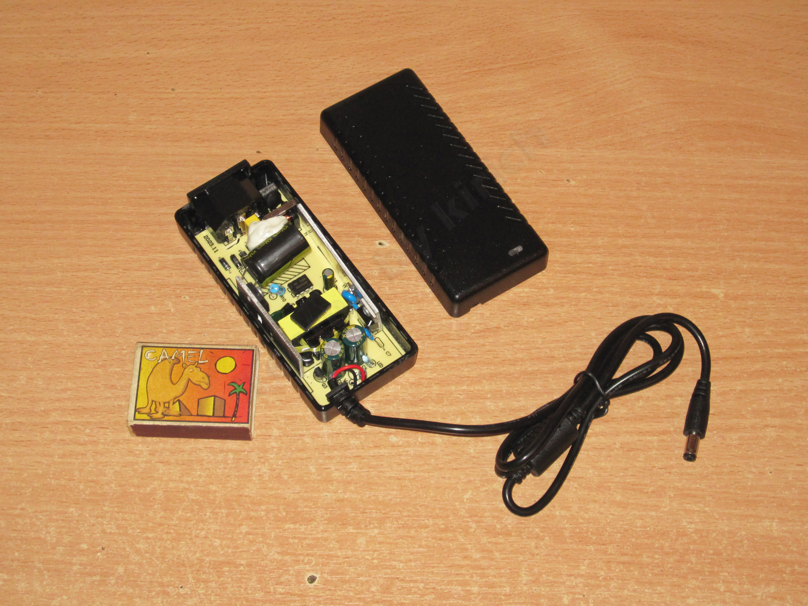
AD-12-3A power supply, 12 V 3 A, price: 167 UAH - link
This one has a case designed for a standard mains cable, which is good.
The input has a filter consisting of an inductor and a capacitor, and they’ve also added a thermistor. The input capacitor is secured with glue, and there’s thermal paste under the power components.
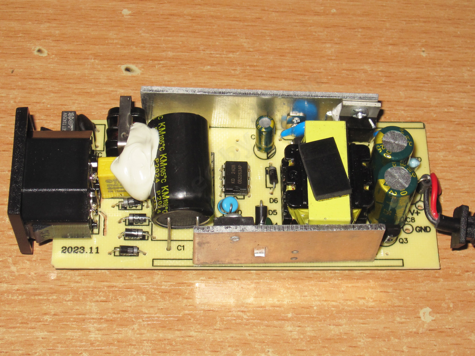
The input capacitor is glued in place. I think it’s 68 µF, but it was awkward to check, so I’ll measure it later.
Judging by the markings, the transistor is probably rated for 10 A and 600 V. Next to it is a current-sense resistor; I think you selected its value to set the optimal protection current.
There’s a Y capacitor, but it’s positioned quite close to the heatsink. More on that later.
The output rectifier is rated for 10 A, which is perfectly adequate. The output capacitors are 1000 µF 25 V, and there’s even a small inductor made from a ferrite tube. It’s tiny, of course, but better than nothing. We asked the manufacturer to use 25 V capacitors instead of 16 V ones, which improves reliability.

At first glance, the circuit board is well and properly laid out. It even has safety slots.
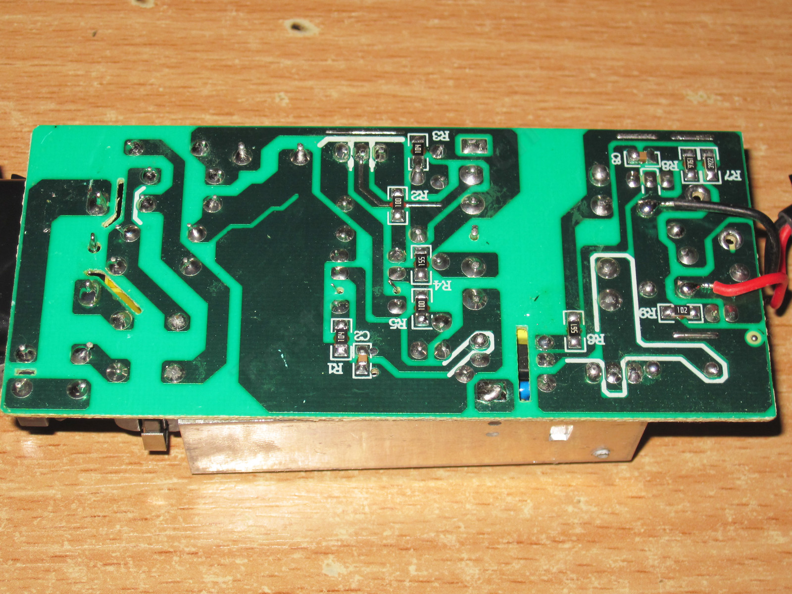
Unfortunately, there is a safety issue. I wrote about it when I first started working with this model, and I’ll mention it again now.
The highlighted copper area in the photo is where the lead that holds the heatsink is soldered. The heatsink carries a rectifier in a non-insulated package.
Without modifying the circuit board (essentially, the heatsink just needs to be moved about 10–15 mm to the right so that its mounting lead is on the cold side of the optocoupler), the alternatives would be:
1. Use a rectifier in an insulated package; the price difference is just a few cents.
2. Coat the board with protective varnish. I can’t say how much that would cost, but I think it would simply be impractical to manufacture.
The right solution is free: move the heatsink. For now, I wouldn’t recommend using this power supply where you could touch the output terminals and something grounded at the same time—for example, the floor or a wall.
A simple, effective way to prevent a short to nearby components is to put insulating tape on the heatsink. Inside the case, it doesn’t significantly affect the heatsink’s performance.
The measured input capacitor value is 60 µF. That’s more than enough for 36 W, and it’s fine even with a 115 V input. The output capacitance is about 2100 µF—excellent.

The overcurrent protection is set to about 3.9–4 A. You’ll see later why it’s set that way.
The no-load output voltage is 12.54 V, and power consumption is 0.45 W. With loads from 0.5 to 3.5 A, the output voltage at the board terminals varies from 12.48 to 12.33 V.
Efficiency is pretty typical, around 84%. Measurements were taken from 0.5 to 3.5 A in 0.5 A increments.
High-frequency ripple at no load and at currents of 1, 2, and 3 A.
Even at maximum power, the main ripple component is only about 30 mV. There are some “spikes,” but their amplitude isn’t very high either. The generous output capacitance helps, as does even the “laughable” little inductor.

The 100 Hz ripple is also fine, thanks to the generous input capacitance.
Interestingly, the “green” mode operates at a relatively high frequency. By the way, all the power supplies tested run quietly, both at no load and in every operating mode.
Temperature rise was checked in four modes, at currents of 1, 2, 3, and 3.5 A. The output voltage does vary with temperature, decreasing by about 60 mV in total.

Temperatures at 3 and 3.5 A.
3 A: transformer 78 °C, excellent; transistor 72 °C, excellent; rectifier 88 °C, excellent.
3.5 A: transformer 86 °C, excellent; transistor 80 °C, excellent; rectifier 101 °C, very good.
We set the protection current experimentally so that the power supply wouldn’t overheat in any operating mode. In other words, either the temperature stays within normal limits or the protection trips—and it isn’t set right on the edge; there’s some margin too. I think we got it right: although rated for 3 A, the power supply can easily deliver 3.5 A continuously, and even more.
And finally, the last power supply, AD-12-4A, priced at 195 UAH - link
In many ways, it resembles the previous one, but it has no input filter. This was a somewhat necessary compromise, but it does have an input thermistor, which in my opinion is much more important. It also has a decent bridge rectifier to improve reliability.
The layout is reasonably compact, and the input capacitor is secured as well.
The input capacitor is rated at 82 µF, 450 V. For improved reliability, there is a 5 A, 650 V transistor, a Y capacitor, a 10 A diode assembly, 1000 µF, 25 V output capacitors (as we required), and here we finally have a proper output inductor.
The board also looks neat.
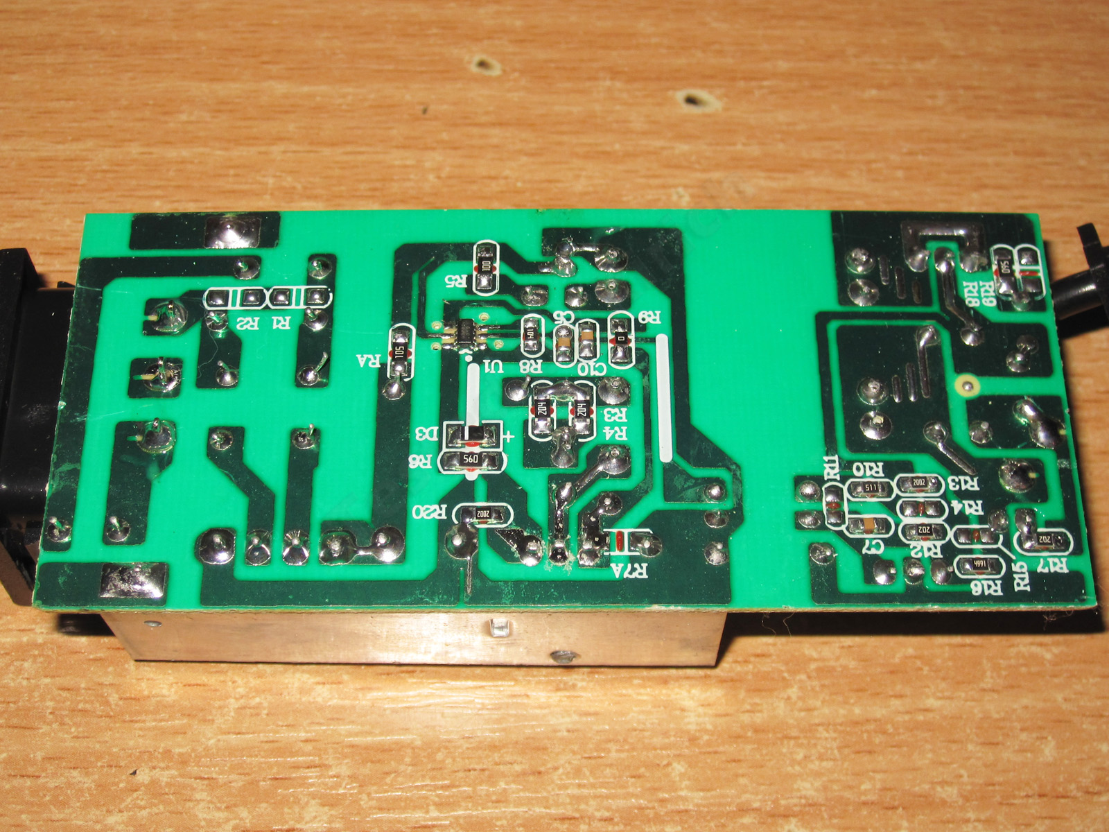
Unfortunately, there is also one safety weak point. We wrote to the manufacturer about it and will keep following up until they fix it.
The issue is that the copper pad where the heatsink-retaining pin is soldered is close to a trace that can be at either neutral or live mains potential.
I recommended improving safety by replacing the output diode assembly with the same type in an insulated package, or moving the traces so this area is safer. We'll try pressing the manufacturer again.

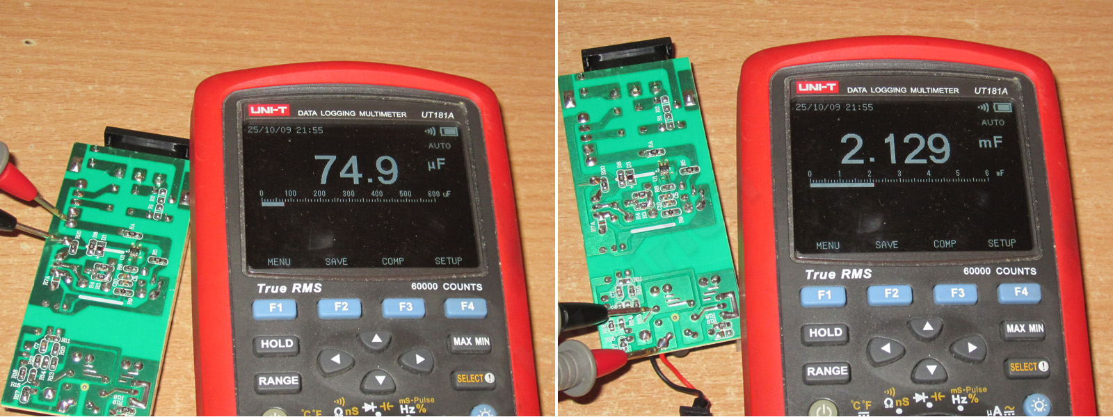
The input capacitor's actual capacitance is 75 µF, and the output capacitors total about 2100 µF, which is quite enough for 230 V and, in principle, for 115 V as well.
The protection trips at about 4.9 A when the power supply is cold and 4.7 A when hot. So we left a little headroom, but didn't go overboard.
With no load, the output is 12.45 V and power consumption is 0.45 W. Across a load-current range of 0.5–4.5 A, the voltage drops from 12.45 to 12.40 V at the board terminals.

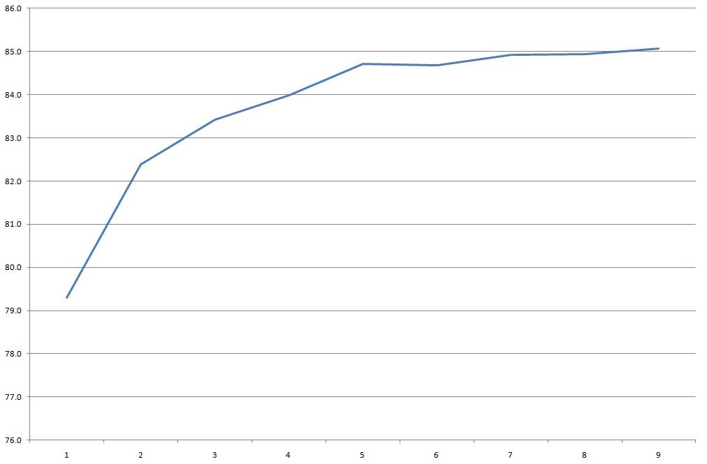
Efficiency is about 83–85% across the 0.5–4.5 A range; the scale below is in 0.5 A increments.
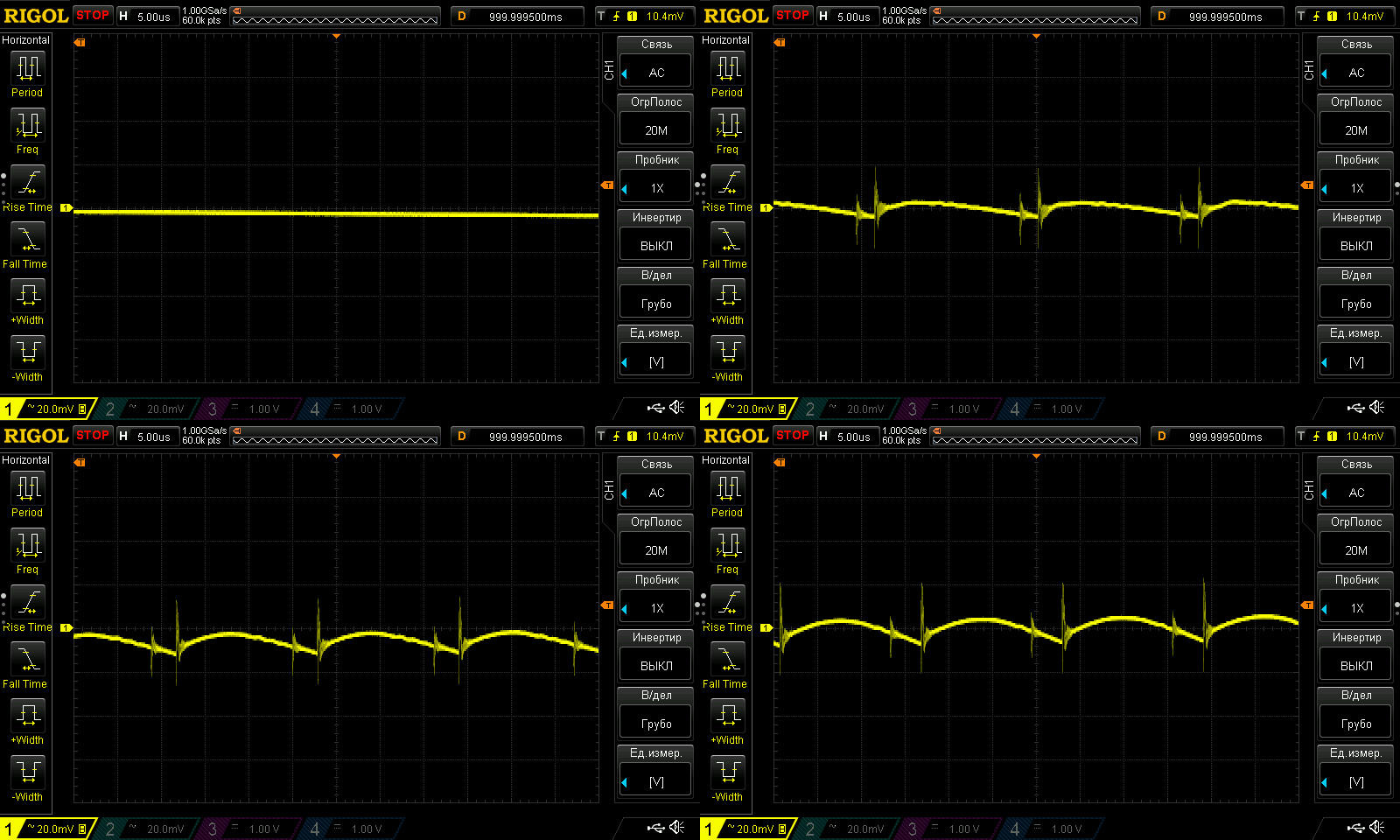
Ripple with no load and at currents of 1.5, 3, and 4.5 A.
Even at 10% overload, ripple is about 15 mV, and just 40 mV including the spikes. Nothing to complain about here.
At 100 Hz, the waveform looks a little odd. The ripple amplitude itself is small, no more than 100 mV, but its shape is hard to explain. I showed something similar above, but this power supply is clearly fine: both the input capacitance and the output filter are adequate.
Still, given the small amplitude, you can simply ignore it.

The thermal test was run at 2, 3, 4, and 4.5 A. The voltage varies by just 10 mV with temperature, which is within the measurement error.

Now for component temperatures at 4 and 4.5 A.
At 4 A: transformer, 86 °C—excellent; transistor, 92.5 °C—perfectly fine; diode assembly, 102 °C—not exactly low, but still with plenty of headroom.
At 4.5 A: transformer, 93 °C—excellent; transistor, 104 °C—acceptable; diode assembly, 111 °C—rather high, but there is still a little headroom.
As with the previous unit, the protection current was set so the power supply would be difficult to overheat. In other words, it runs reliably at 4.5 A (more than 10% overload), but if you increase the current further, it trips into protection. And of course, the power supply delivers the claimed 4 A without any problems.
And now, a quick summary of all the models.
1203 - This would be a decent power supply if not for its wildly excessive overcurrent protection threshold: 5.7 A instead of the claimed 3 A. I think it could be made viable with a few adjustments.
1204 - The protection current is fine, as are the temperature and safety, but the ripple is a little high. I think it could be tuned up and would make a decent power supply too.
1205 - In practice, its specs are very close to the previous model, perhaps a touch more powerful, so there isn't much point in choosing it. It may be easier to tune up than the previous one, but this would then be a model rated for a real 4 A.
1206 - A rather disappointing unit, especially because of the excessive heat. Formally, this is a real 3 A power supply. There's no point in modifying it; it's more trouble than it's worth.
1207 - The ripple is somewhat high. I think it can be improved, but given the heat, this is a real 5 A power supply, or thereabouts.
1208 - If it were relabeled as a 1206, it would be a fairly decent power supply, provided the manufacturer doesn't decide to use no-name output capacitors instead of quality ones.
АД-12-1А - The output diode overheats at maximum load. Apart from the lack of an input filter, that's the only issue. Perhaps this will be addressed in future revisions.
АД-12-2А - Essentially the same as the previous model: the output diode gets too hot at maximum current. Add a second diode and that problem goes away too.
АД-12-3А - The only concern is safety. Otherwise, this power supply can actually run continuously at a higher power than its rating, and since the output capacitors are rated for 25 V rather than 16 V, it will probably last a long time too.
АД-12-4А - The conclusions are exactly the same as for the previous model: a good unit with plenty of power headroom, but with some safety concerns.
If you've read the article carefully, you've probably noticed that I mention safety quite often. The point is that this has absolutely nothing to do with a power supply's performance. In other words, you can have a power supply that produces ripple and gets hot as an oven, yet is completely safe—and vice versa: excellent power delivery, but not so safe.
But the point is, consider this my personal "quirk." I've encountered similar safety issues many times, even in quite reputable products sold in large quantities, with nobody complaining. Personally, though, I consider this important (under certain operating conditions), and I'll always strive to make a device not only high-quality but safe as well. So if, following our recommendations to the factory, we get an inexpensive, reliable power supply with good performance, the next step will be to make it as safe as possible too. Unfortunately, we can't do everything at once. If you don't understand why, try talking not just to a seller on AliExpress, but to the manufacturer. You'll see: a batch of 1,000 units is practically a retail order, and it's hard to find a competent engineer there.
That's all for now. I really hope this was useful, and thanks again to Vitaly for providing the samples.
This page was found when searching for:
плата блока питания 12 вольт 8 ампер, 2, что можно сделать из блока питания от ноутбука своими руками
плата блока питания 12 вольт 8 ампер, 2, что можно сделать из блока питания от ноутбука своими руками
This model is included in the summary table: Comparison of power supplies: ripple, efficiency, and temperature rise
The figures from this review are in the measurement database: Power supplies
Calculate manuallyAll calculators
Discounted products
You may be interested in



Discounted products
Support the project
All the content on the site and the advice are free, but we’d be grateful for your support of the project and the channel!
Comments4
Discuss on the forumHave a question or some experience to share? Discuss the article with the author and readers: the forum is a convenient place to share schematics and photos.
Go to the forumOnly registered readers can comment. It takes a minute to sign up, and you can log in with the same account you use on the forum.
Log inRegister
Comments are published in their original language.