
Ukraine's Power Supply Market, Part Two: Seven More Models
Last time I covered three power supply models. Today there are as many as seven units under test, all bought from a different, but also fairly well-known store—"widely known in certain circles," so to speak.
To keep up with new posts on the blog, I recommend following me on Instagram, where I'll post notifications about every new article and maybe write about something interesting now and then: link to my account
You can also subscribe to updates and new articles on the Telegram channel - https://t.me/KirichBlog Note that discussion of reviews and articles is enabled on the channel, along with general chat. I recommend it.
A note: to avoid any accusations, and as agreed with the project sponsor, the labels on all the units under test have been removed. Any resemblance to particular brands is coincidental. Otherwise, I promise this review will be as unbiased as possible—as are all my reviews.
Also, remember that you may use material from this blog only with the author's permission and with an active link to the original article.
As I mentioned, there will be seven models, arranged in order of increasing rated (not necessarily actual) power.
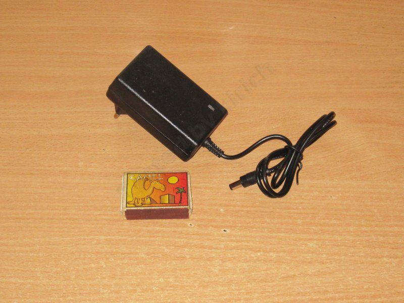
First up: a "wall outlet adapter" style unit, rated at 36 W, 12 V, 3 A.
The stated input voltage range is 100–240 V.
Inside, it's a fairly typical low-cost design, though I should point out that it does have an input filter, even if it's just a choke.
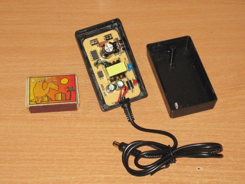
The circuit board is neatly laid out. This is pretty much the classic design for low-cost power supplies.
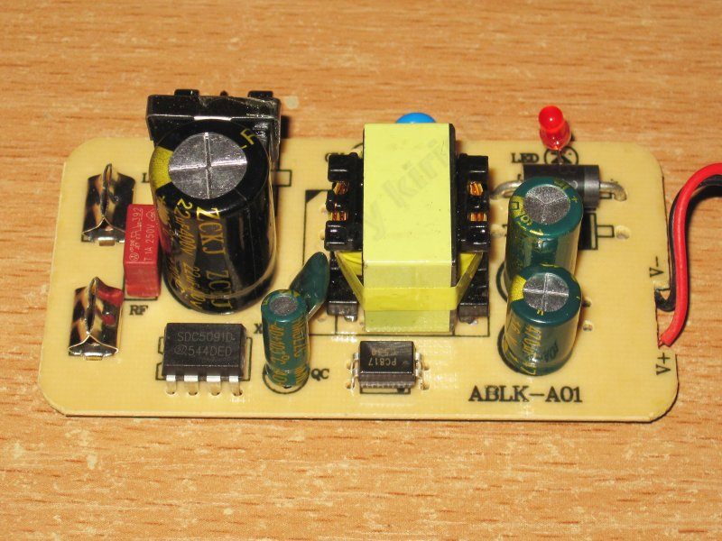
1. It uses an SDC5091 chip, designed for power supplies rated at 24–30 W. Having a chip like this is a plus, since they usually include overtemperature protection. But this is a 36 W unit, while the chip is rated for 30 W.
2. It has a Y capacitor. That's good.
3. There's a single output diode, a typical 3 A, 100 V part.
4. The output has a pair of capacitors, 680 + 470 µF. An odd combination, but that's a minor detail.
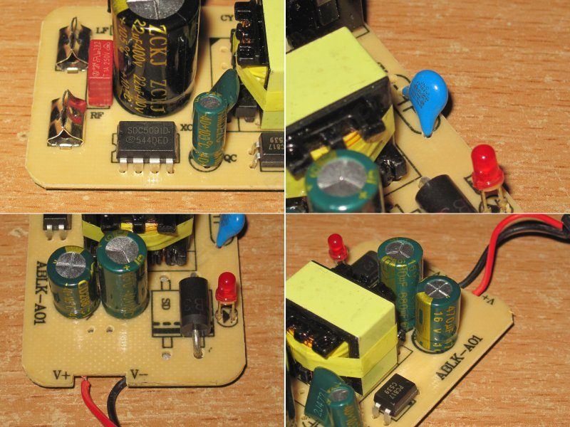
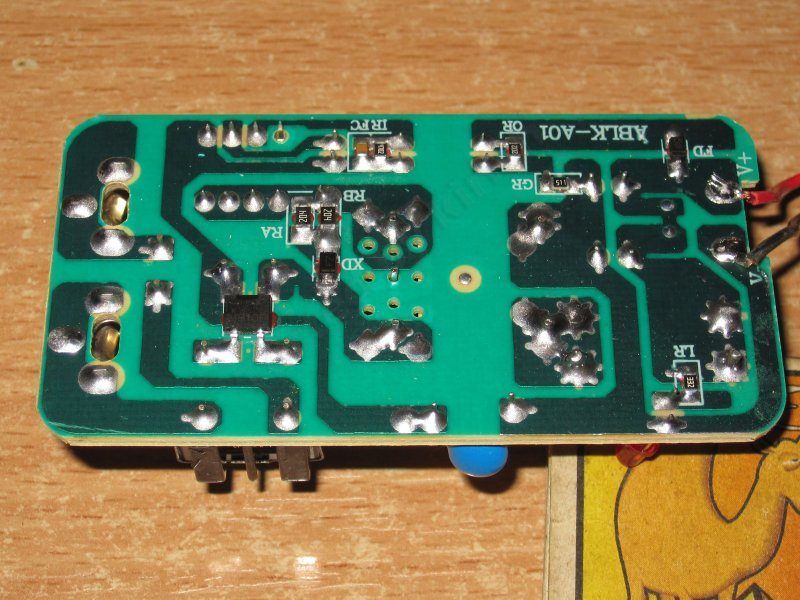
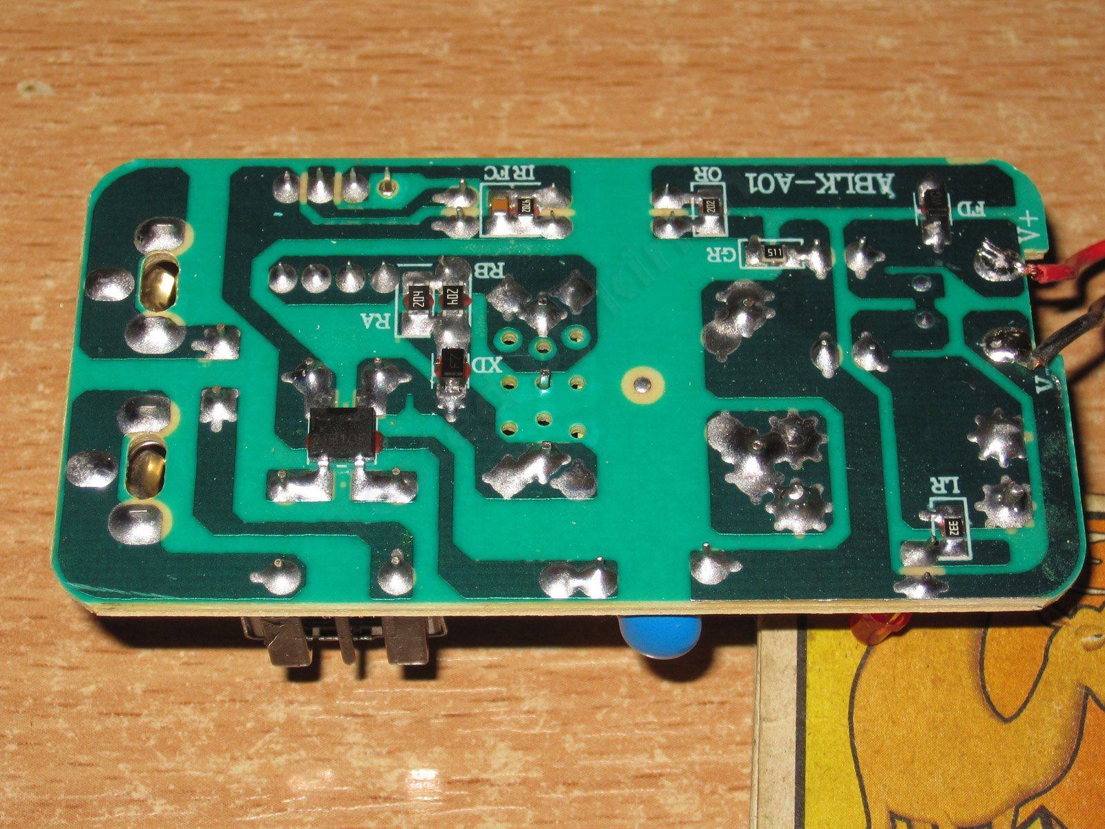
The underside is clean, if a little sparse, but that's normal with chips of this type. The feedback is simply through a zener diode, so the output voltage will probably fluctuate a bit.
The clearance between the Y capacitor's leads is very tight.
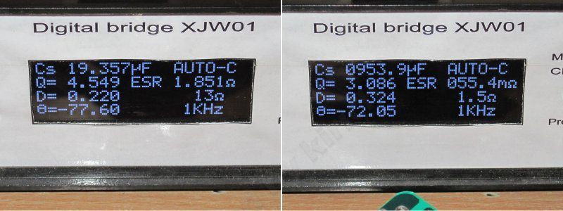
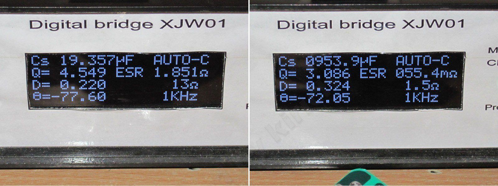
The input capacitor's actual capacitance is about 19 µF. That's just about enough for a standard 230 V mains supply, and too little for the stated input range starting at 100 V.
The total output capacitance is about 1000 µF, which is fine.
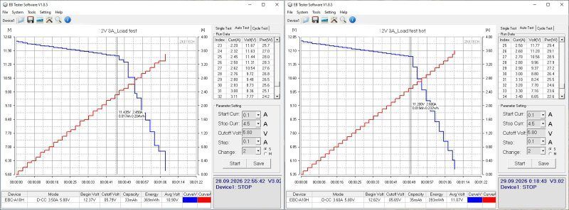
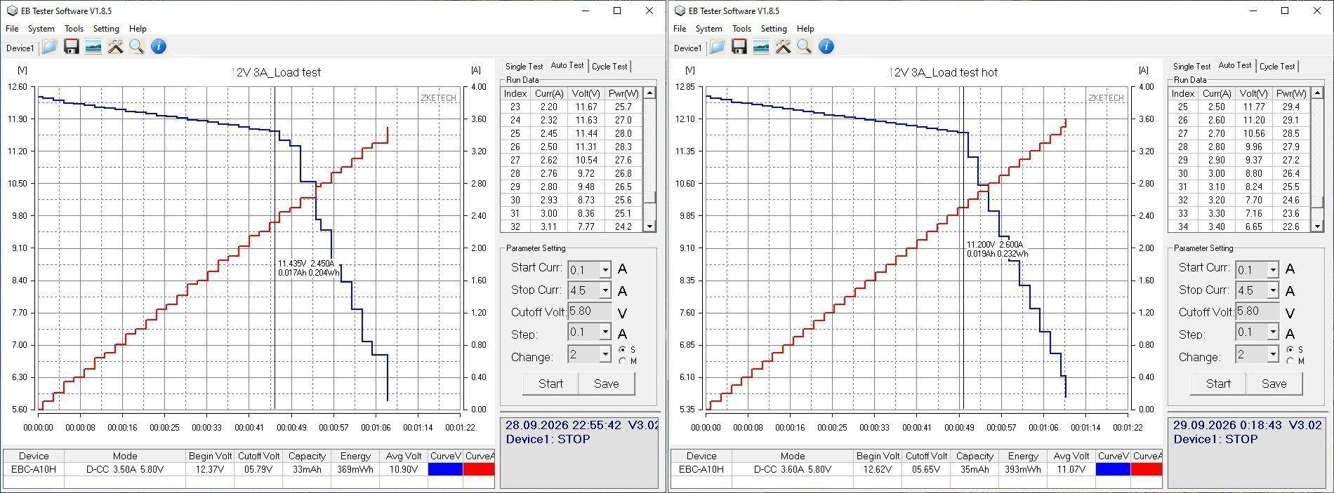
As expected, the protection kicked in at around 2.5 A with the power supply cold, and at 2.6–2.7 A when hot. So we won't be getting the rated 3 A. Under overload, the protection gradually reduces the output voltage depending on the current.
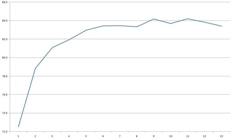
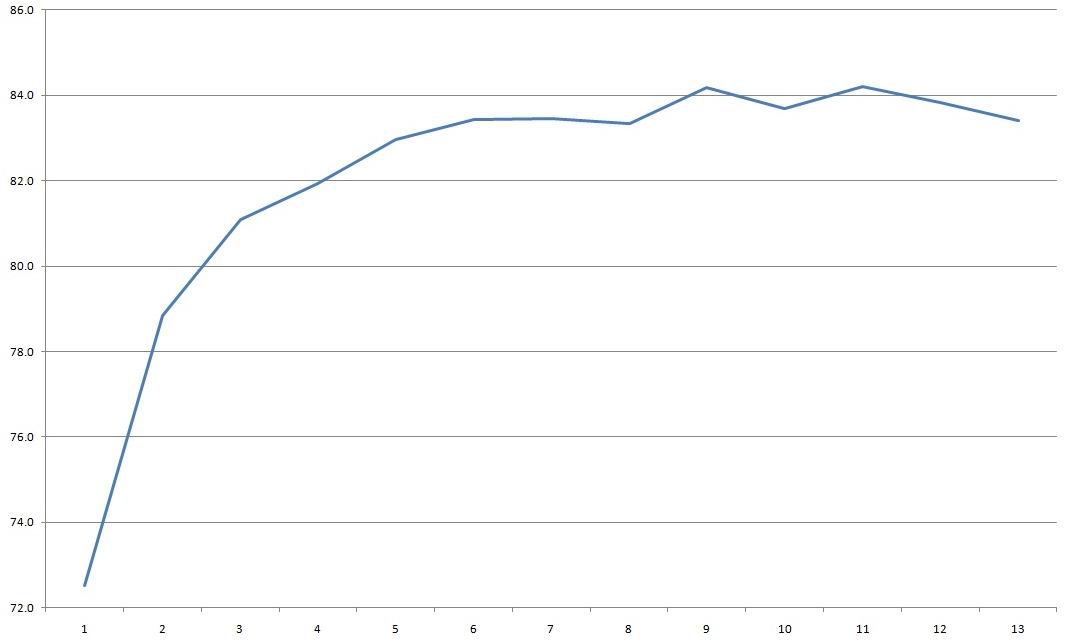
Efficiency is around 84%, which is normal for low-cost units.
Since we won't get 3 A, I captured the waveforms with no load and at currents of 0.7, 1.4, and 2.1 A.
Well, this is pretty much what you'd expect: about 200 mV for the main component and 400 mV peak-to-peak. Typical results for power supplies at the low end of the price range.
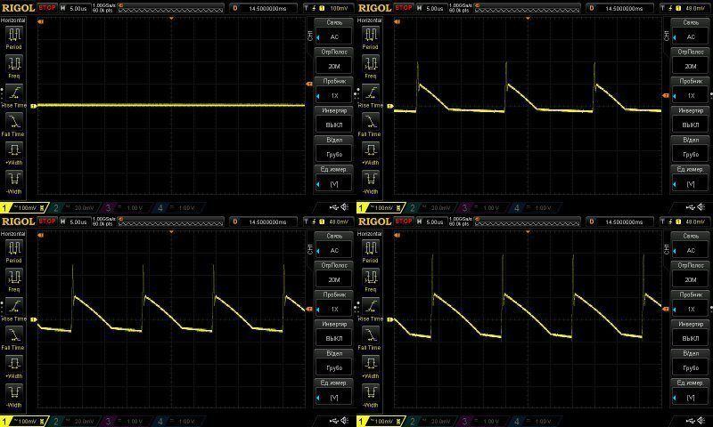
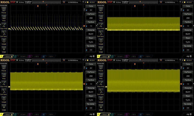
The first waveform suggests that the PWM controller has a "green mode," but the power supply was quiet with no load.
Otherwise, the results are typical too.
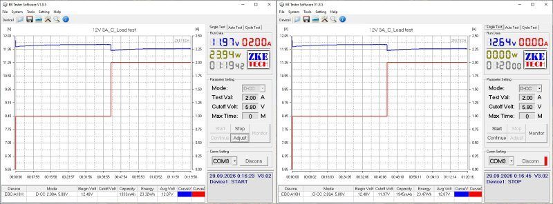
The load test was run in two modes: 1 A and 2 A.
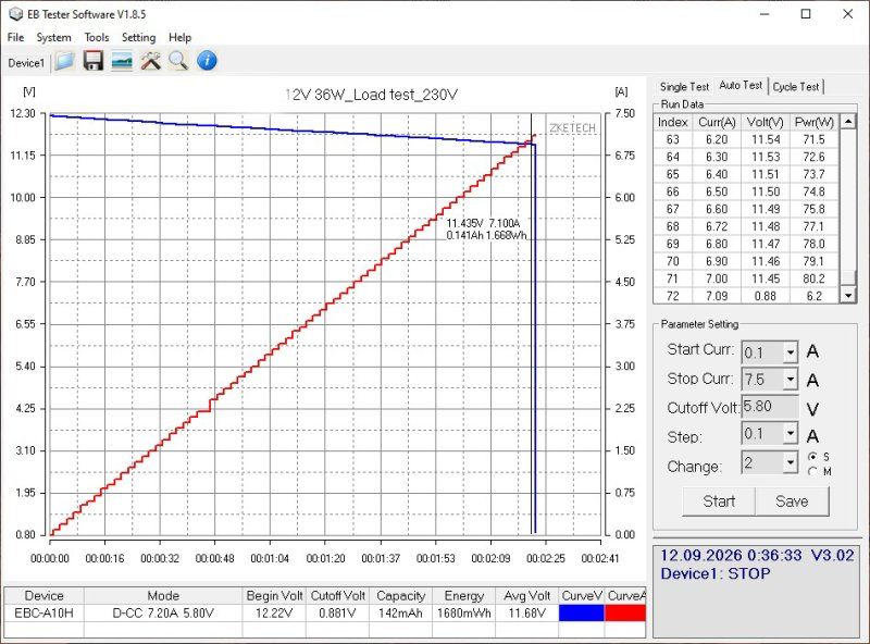
Note that the graph already shows a positive relationship between voltage and temperature. "Positive" doesn't mean "good" here; it means the voltage rises as the unit heats up or the load increases.
As a result of heating, the voltage rose by 0.24 V. This is due to the simple implementation of the feedback circuit.
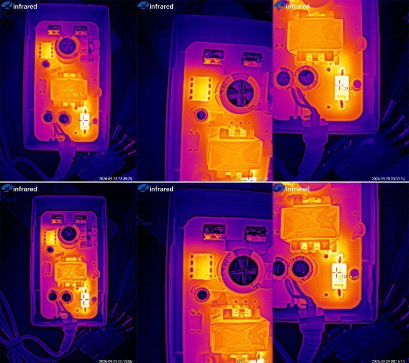
Key component temperatures:
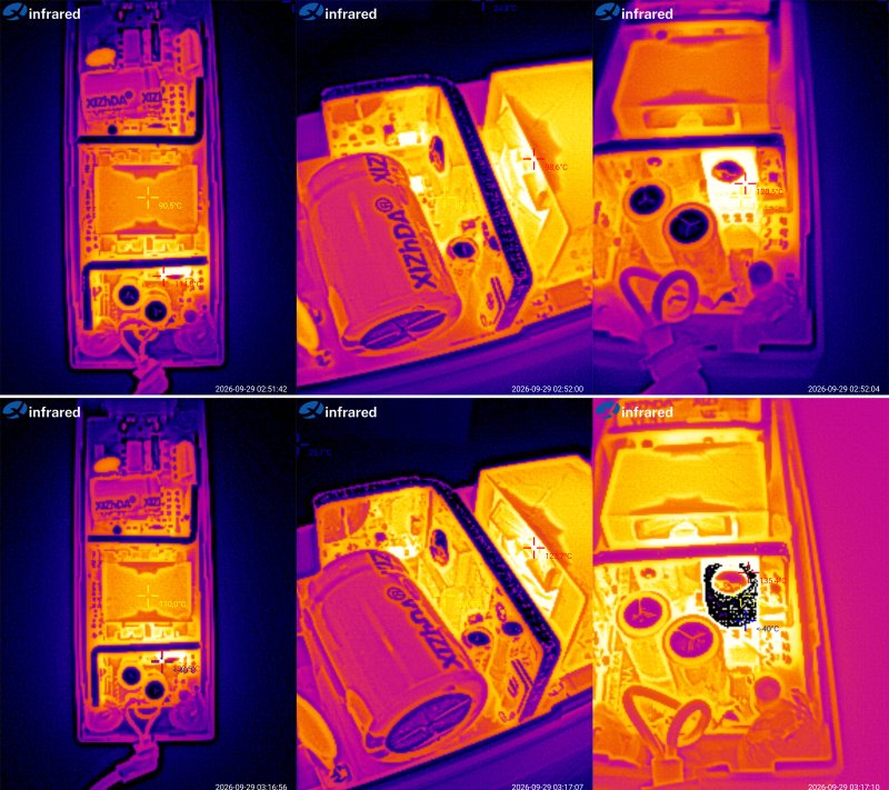
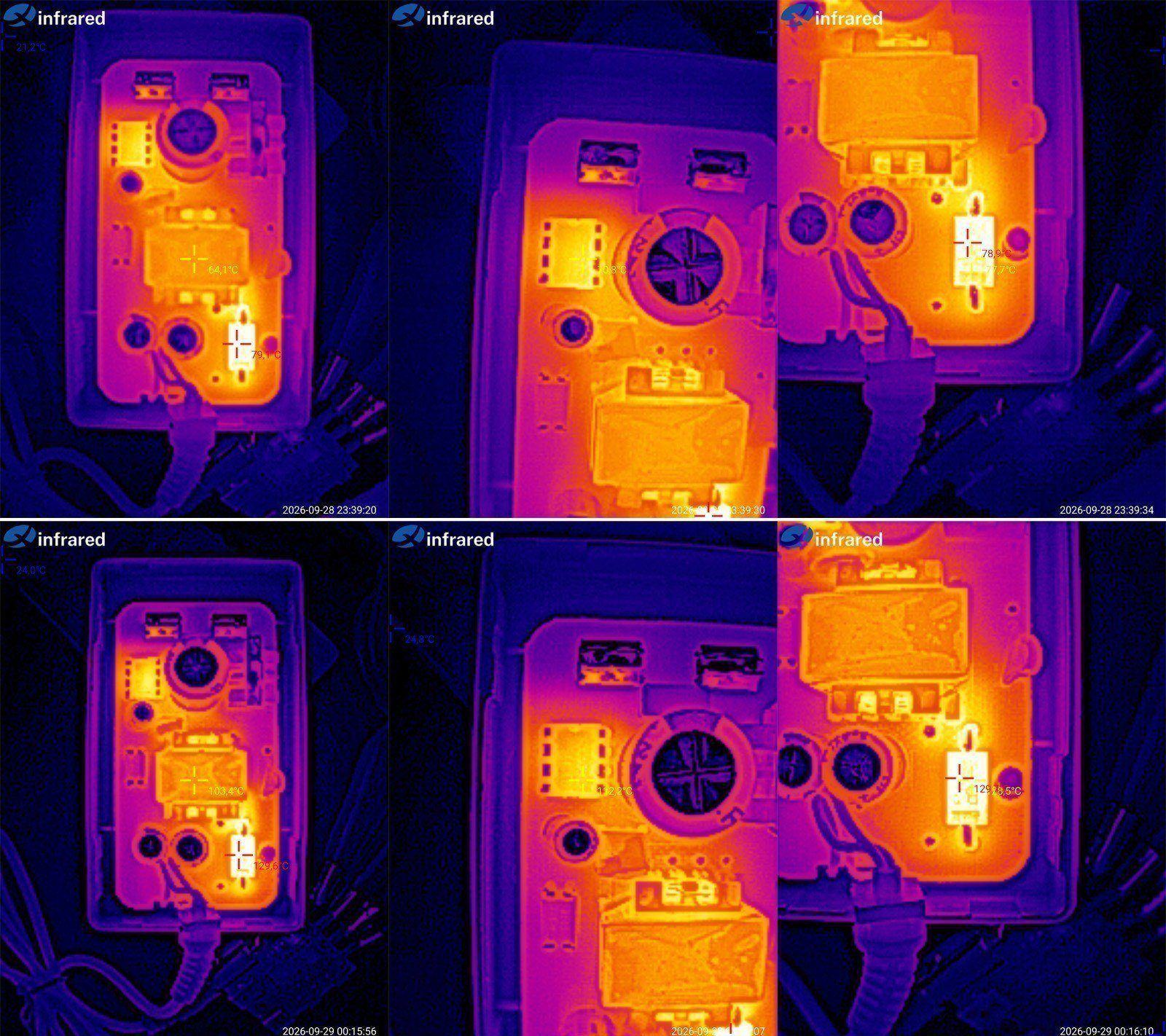
1 A: transformer 64°C, PWM controller 71°C, output diode 79°C
2 A: transformer 103°C, PWM controller 112°C, output diode 130°C.
As the thermal image shows, even 2 A is too much for this power supply to handle continuously. The temperatures of all the main components are close to their maximum, and that's at normal room temperature. So the actual output current of this model is closer to 1.6–1.8 A.
The second model is a desktop version, rated at the same 12 V, 36 W, 3 A.
The stated input voltage range is 100–240 V.
This one comes with a cable as well as the power supply—a standard “computer” power cable, which is handy..
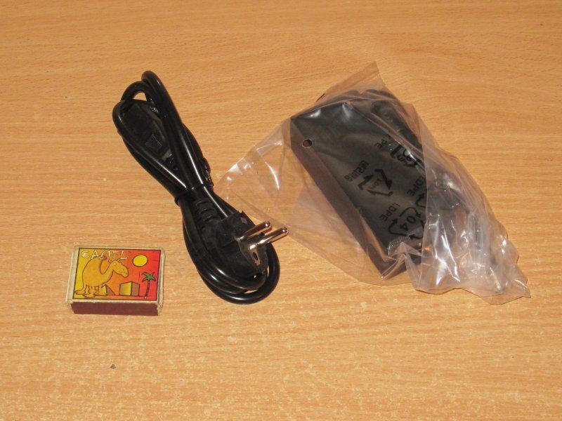
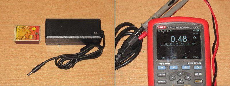
It looks pretty good. I like that the output cable exits at an angle; that can be genuinely convenient sometimes.
The mains cable resistance is about 0.5 Ω. That’s not exactly good—higher-quality cables are closer to 0.15–0.3 Ω—but I wouldn’t call it bad either; there are much worse ones out there.
The “guts” here are completely different from the previous model. It feels like there are about twice as many components :)
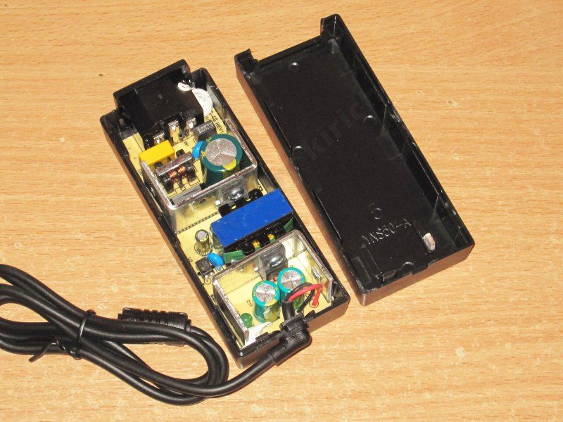
There’s an input filter, a pair of decent heatsinks, and a transformer that’s larger than the one in the previous model.
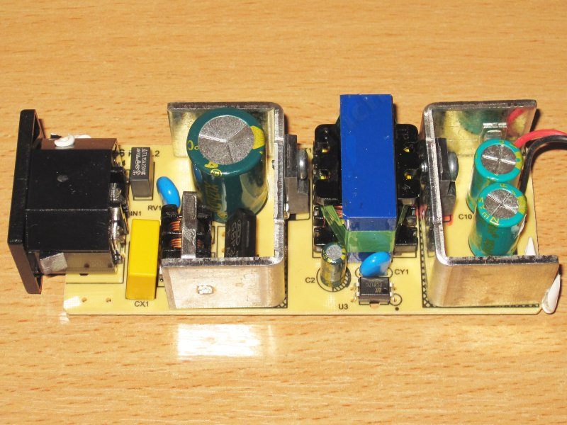
1. The only thing missing from the input filter, I think, is a thermistor.
2. They did fit a varistor, rated for 470 V peak.
3, 4. The Y capacitor’s leads are surprisingly close together. I even desoldered it to check, because I was sure it was an ordinary high-voltage capacitor, but no—the markings confirm it’s a Y capacitor. Y capacitors usually have their leads spaced about 1.5–2 times farther apart to meet safety requirements.
5. The output diode assembly is rated for 10 A, 100 V, which is perfectly adequate for this SMPS.
6. There are two 1000 µF, 16 V output capacitors, which is also fine.
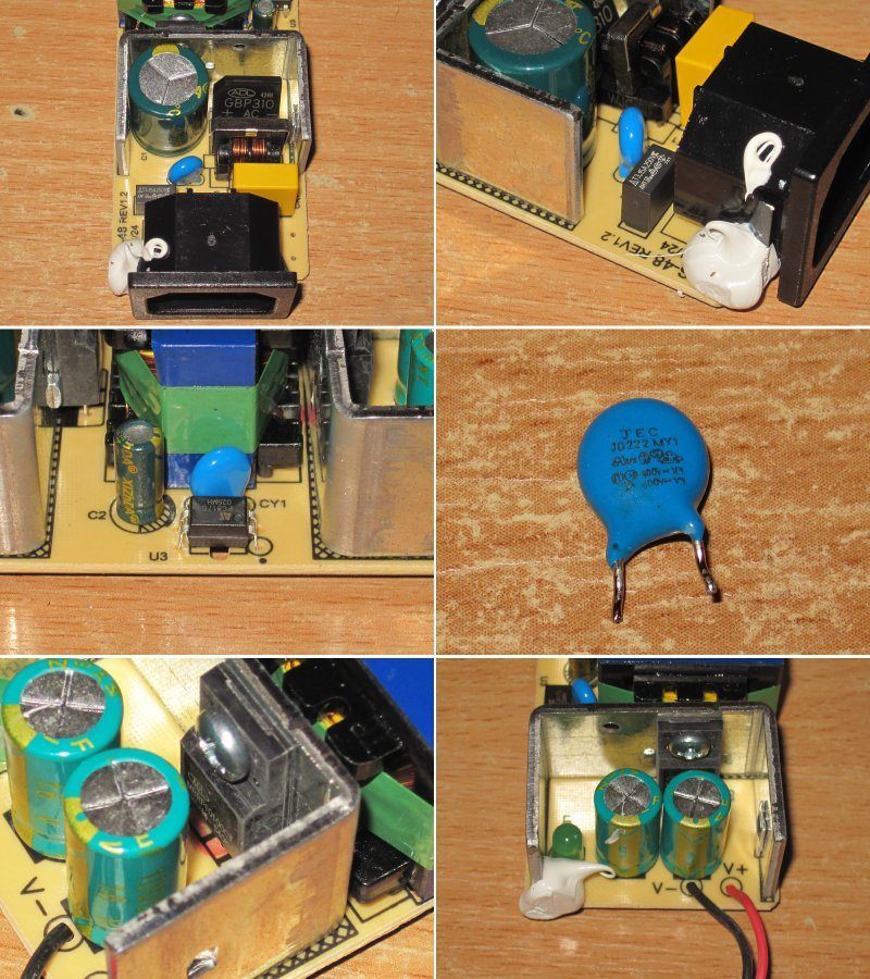
The board looks very neat, and protective slots have been cut in the “tight” areas, so I have no complaints here.
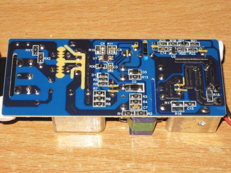
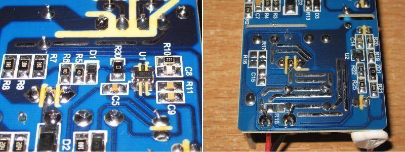
The PWM controller is a TC6368C. There’s no thermal protection, of course, which is expected, but I’ll note that the board is laid out properly, with solder added to reinforce the copper pours in high-current areas.
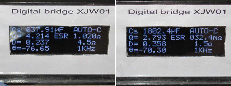
The actual input capacitor is 38 µF, and the output capacitors total 1800 µF.
For the upper end of the 230 V mains range, 38 µF is enough; for the lower end, it’s too little, unless you reduce the load power.
The protection threshold is ridiculously high—over 7 A, despite the stated rating of 3 A....
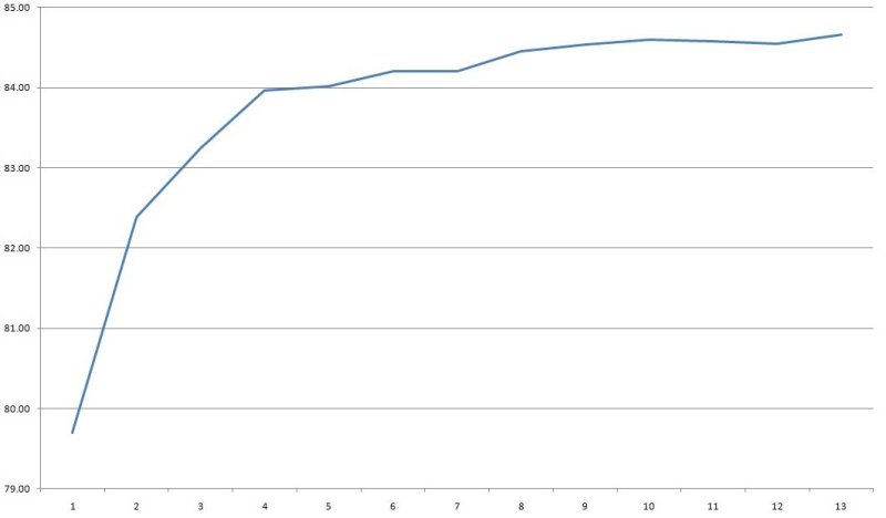
Efficiency across the 0.3–3.9 A range was about 84–84.5%; each division on the scale at the bottom represents 0.3 A.
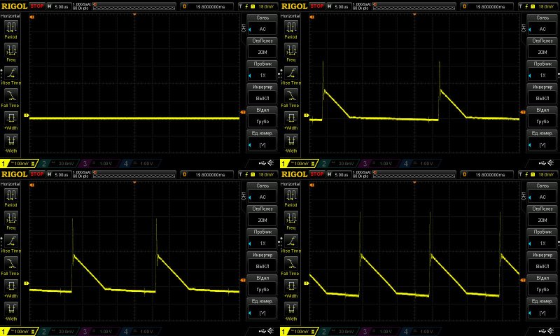
Ripple with no load and at currents of 1, 2, and 3 A.
It’s 250 mV for the main ripple and 500 mV including the “spikes.” That’s arguably tolerable for an inexpensive power supply, but judging by its appearance, this one isn’t all that budget-friendly, so they could have done something about it.
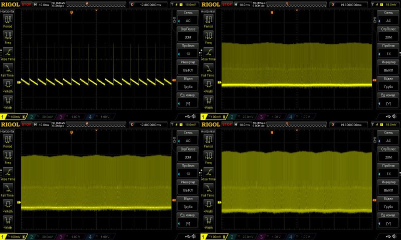
At low frequency, you can see the “green mode” operating with no load. The 100 Hz ripple is noticeable under load, but that’s about it—it gets lost in the overall noise.
The load test was run in three modes, at 1.5, 3, and 3.5 A.
The power supply has a slight negative voltage drift as it warms up—just 10 mV.
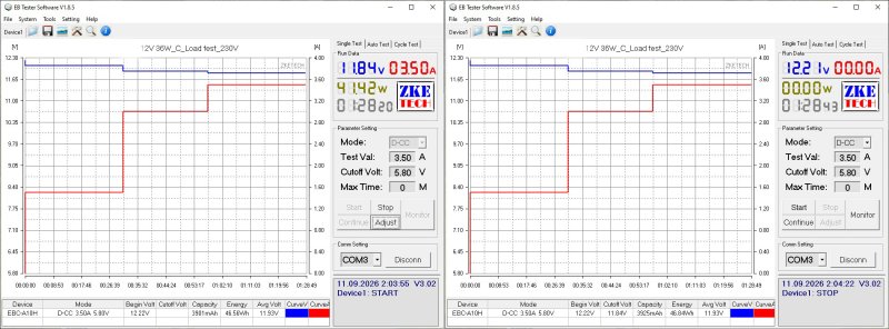
And now for the temperatures of the main components.
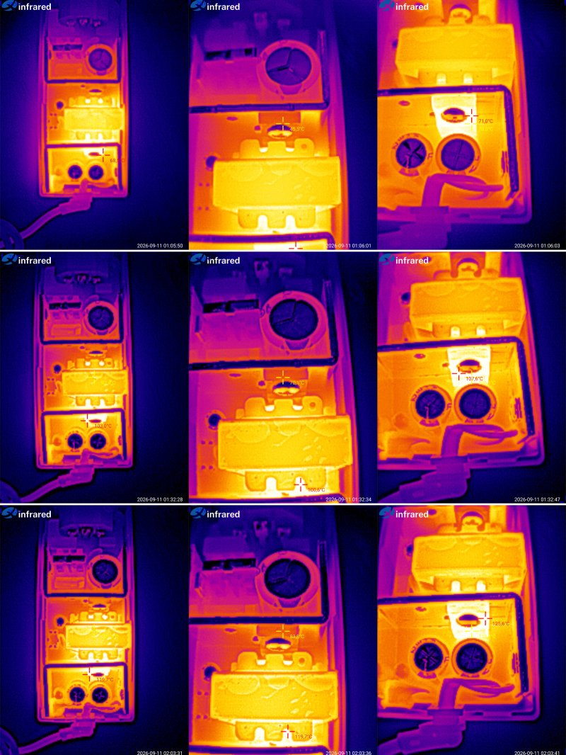
1.5 A — transformer 64 degrees, transistor 45, diode assembly 71 degrees.
3 A — transformer 92 degrees, transistor 70 degrees, diode assembly 108 degrees.
3.5 A — transformer 109 degrees, transistor 84, diode assembly 126 degrees.
It can deliver its rated 3 A with almost no trouble, but judging by the temperatures, I’d say it’s running pretty close to the limit, i.e. almost no headroom for ambient temperature.
That said, I should note that the heating can even be called well balanced, and there is some headroom for the high-voltage transistor to heat up.
The only thing that really concerns me is the very high overcurrent protection threshold and the lack of thermal protection—the issue is specifically how the two are related.
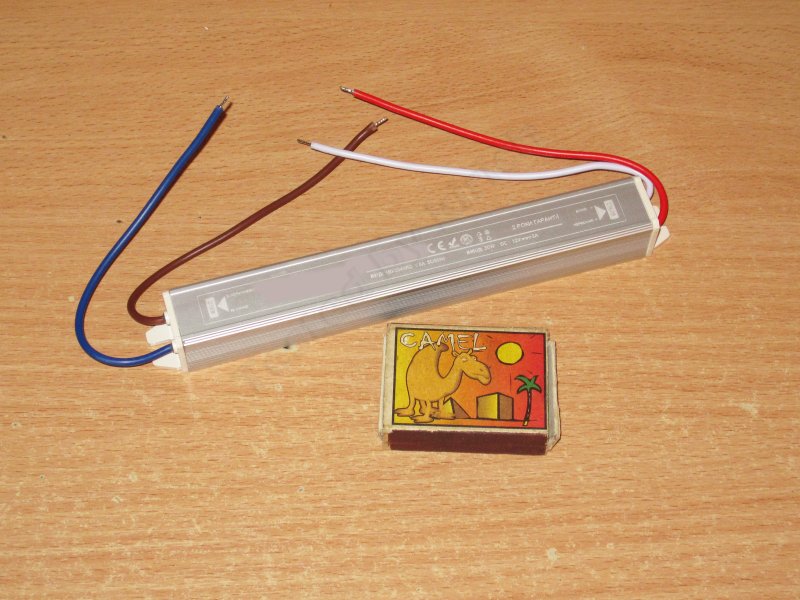
The third power supply is rated at 36 W, 12 V, 3 A, but this time it’s a sealed model.
The input voltage range is “narrow at the top”: 180–264 V.
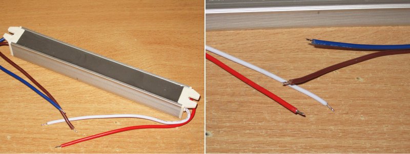
As for the construction, it’s the usual design: a U-shaped aluminum channel with a long, narrow circuit board inside, potted with compound. Given the relatively low power, all the heat is dissipated through the compound alone.
I wouldn’t call the wires thick, but on the other hand, the load current here is low, so it’s fine.
Unexpectedly, the overcurrent protection is even set correctly, at about 3.3–3.4 A depending on the case temperature.
There’s a slight negative relationship between output voltage and load, mostly due to voltage drop in the wires.
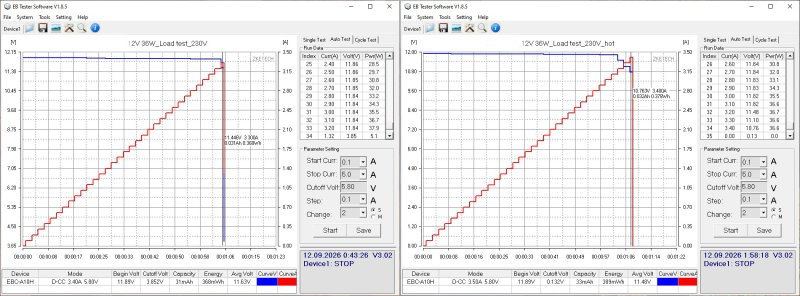
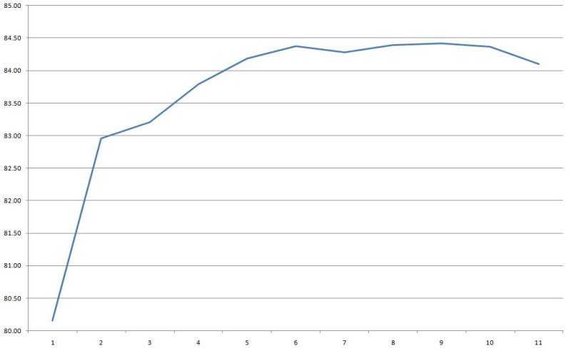
Efficiency is about 84%, measured from 0.3 to 3.3 A in 0.3 A increments.
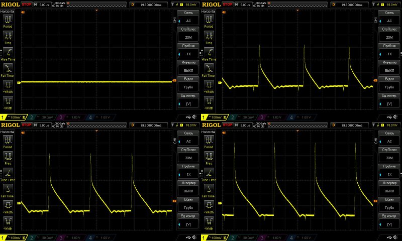
Ripple with no load and at currents of 1, 2, and 3 A.
Usually, when you measure ripple after the output wires, the “spikes” have a smaller amplitude, but that didn’t really help much here.
So the main component came out to around 300–400 mV, with a total amplitude of 600 mV. That’s quite a lot; I’d guess there’s a single ordinary capacitor of around 1000 µF on the output.
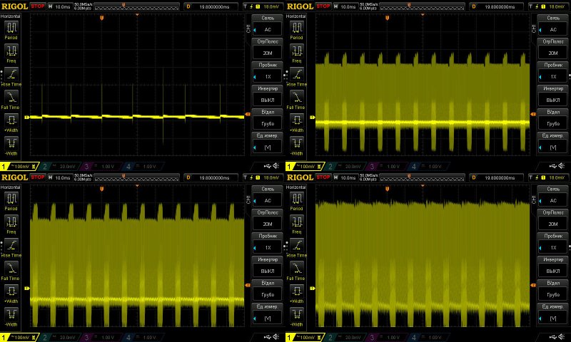
At low frequency, the picture is even worse. Judging by the ripple pattern, it may be caused by the way the PWM controller operates, but either way, it doesn’t look very good. I actually came across something similar recently, with one difference: although it looked very much the same, the total amplitude there was around 80–90 mV, while here it’s 700–800 mV, which is obviously disappointing.
The load test was performed at 1.5 and 3 A. It showed that output voltage does not depend on temperature, within the measurement error.
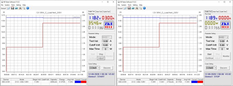
There wasn’t much to photograph. The first thermal image shows the overall view at 50% load; the next three are at 100%.
The highest recorded temperature was about 70°C, and judging by its location, that’s the transformer. The rectifier is clearly to the right, a little cooler at about 62°C.
In any case, I have no complaints about the heating, at least in its current form.
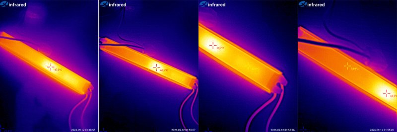
A desktop model rated at 72 W, 12 V, 6 A.
The stated input voltage range is 100–240 V.
The cable exits in the more familiar straight-through arrangement, and it comes with a standard “computer-style” power cord.
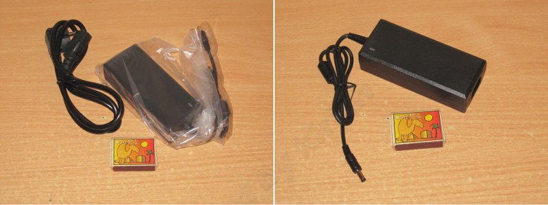
The layout is very similar to the 36 W desktop model shown earlier, but it’s clear that the transformer is larger and the input capacitor has a higher capacitance. Even at a glance, you can tell this power supply is more powerful.
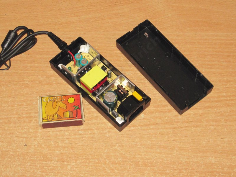
The board is secured inside the case with three blobs of sealant. If it holds, why not? I think that’s better than simply pressing the board against the transformer with a rubber pad.
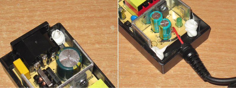
The layout is typical, with U-shaped heatsinks. I actually like this arrangement, although it works less well in a closed case than when the heatsinks run along the board.
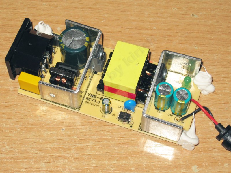
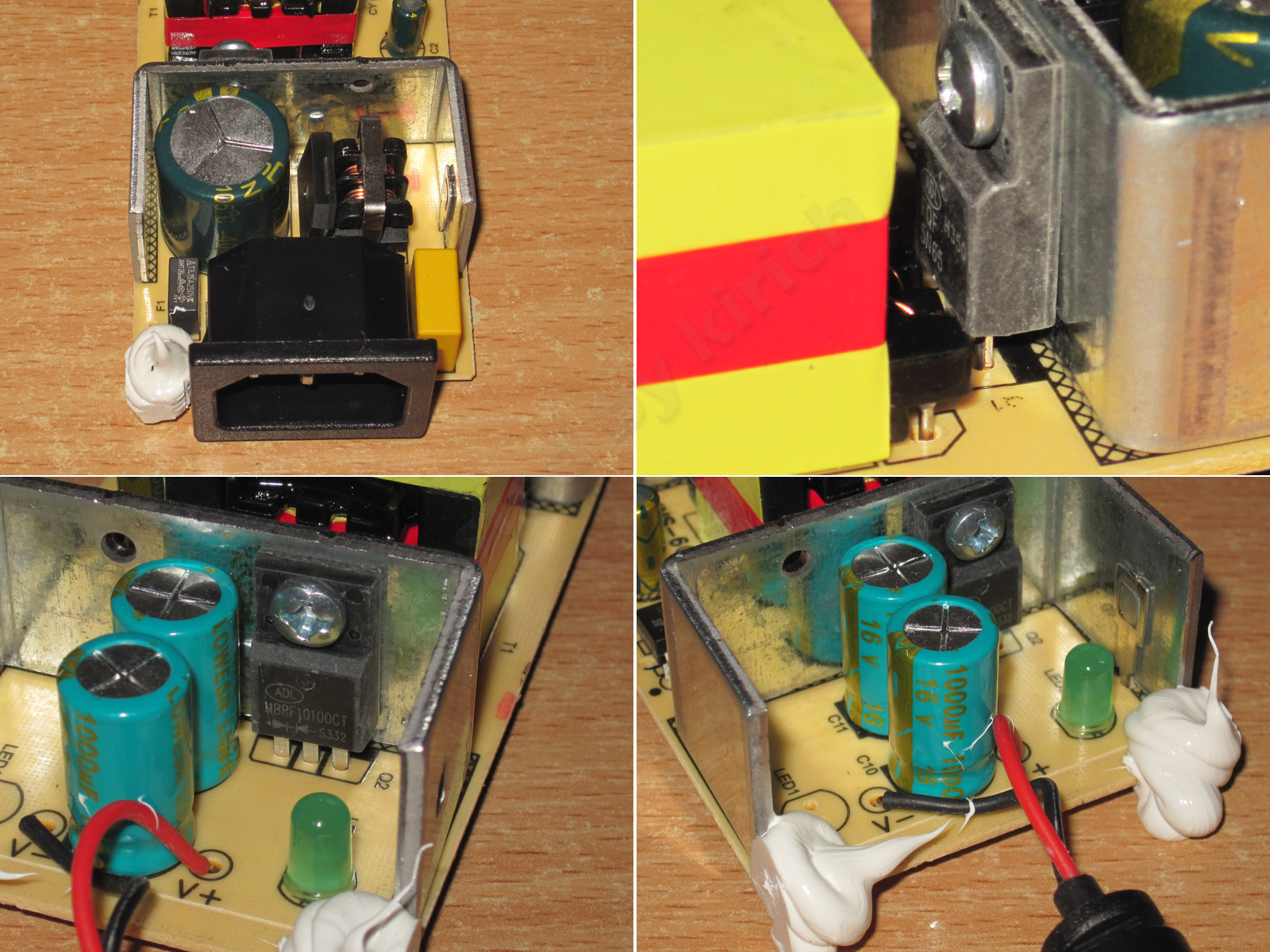
1. It has an input filter, but they skimped on the varistor—and on a few other things, too.
2. A 5 A, 650 V transistor, which is a typical choice for this power rating.
3. A 10 A, 100 V output diode assembly, which is a bit undersized for a 6 A power supply, though it should work.
4. A pair of 1000 µF, 16 V capacitors.
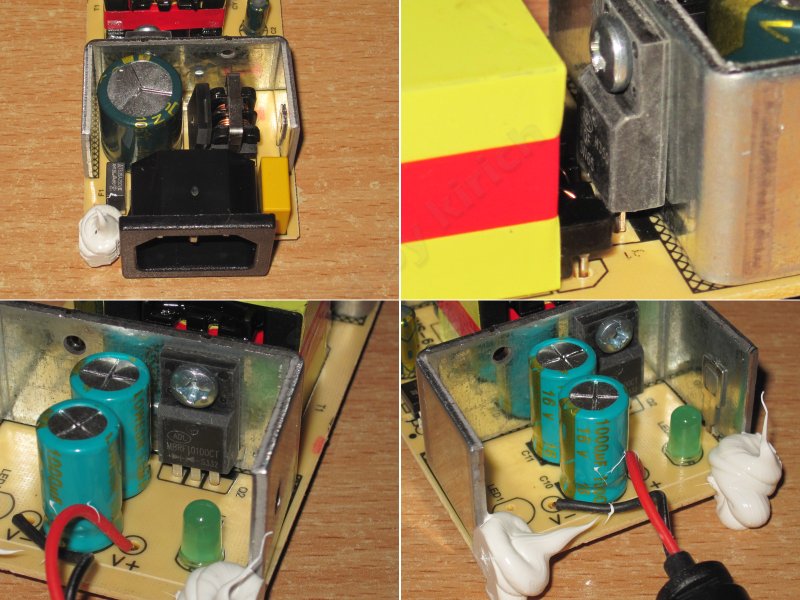
The board is very neatly laid out. I’ll note the proper topology of the output power stage.
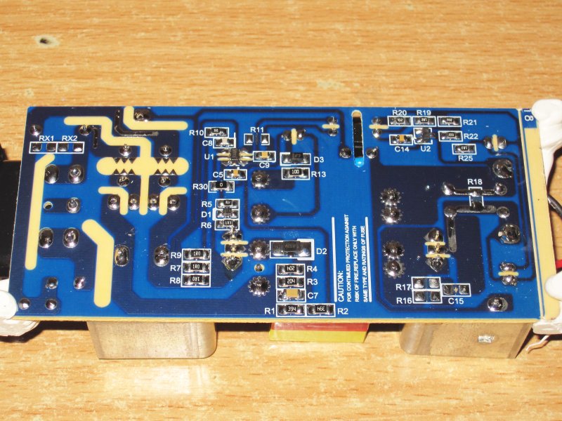
The input capacitor’s actual capacitance is 50 µF, which is on the low side. The output capacitors add up to about 1700 µF, which is also not much.
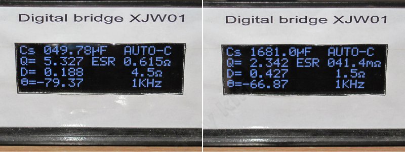
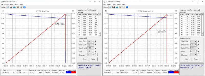
The protection is set to trip at around 7.3–7.4 A. That’s basically fine for a 6 A power supply, even if it’s at the upper limit, but in this case it’s best to look at the load test results.
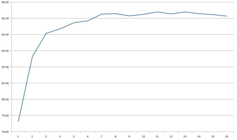
Efficiency was measured over a range of 0.4–6.4 A and came in at around 85–85.5%, which seems fine to me.
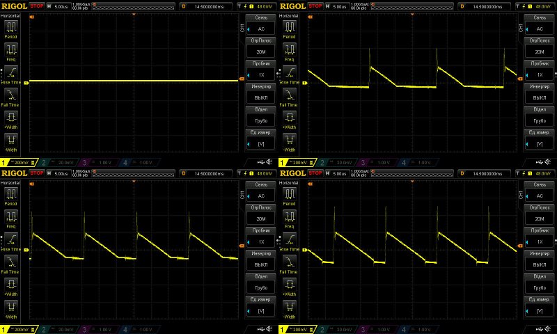
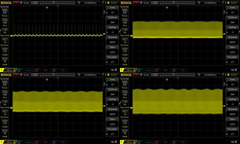
Ripple with no load and at currents of 2, 4, and 6 A.
Somewhat high: the main component is about 380 mV, rising to nearly 650 mV if you include the “spikes.”
At low frequencies, it’s basically fine, aside from the large overall swing. There are no particular issues at 100 Hz.
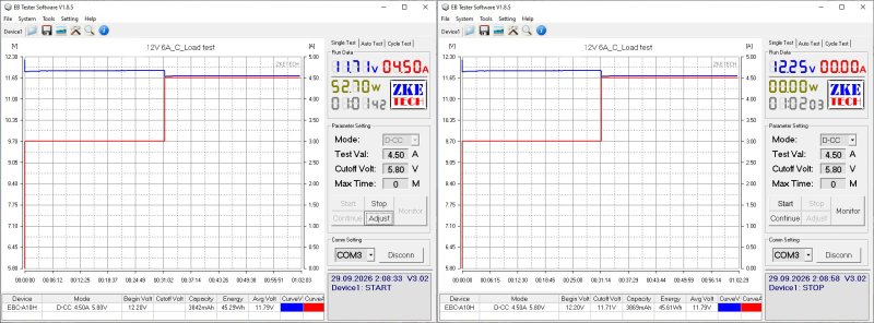
The load test was first run at 3 A, then, based on the temperature readings, at 4.5 A rather than the expected 6 A.
The voltage has a slight positive temperature coefficient, around 50 mV, which can safely be ignored.
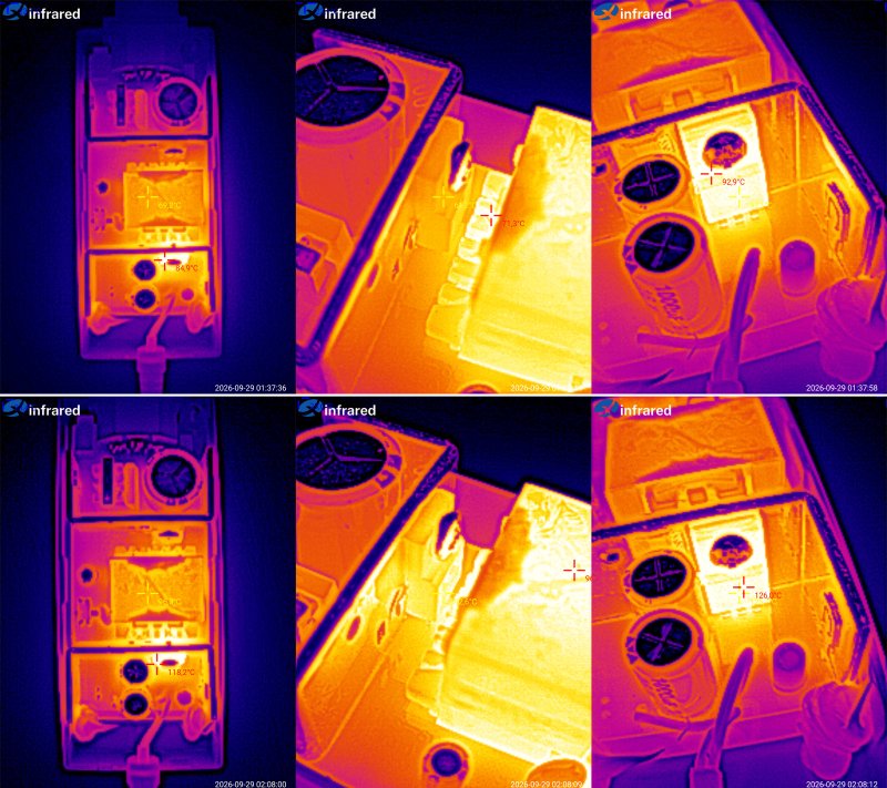
Temperatures:
3 A — transformer 69°C, transistor 61°C, diode assembly 93°C
4.5 A — transformer 96°C, transistor 93°C, diode assembly 126°C.
The temperature rise is why I ran the second part of the test at 4.5 A instead of 6 A: 4.5 A is the maximum continuous current at room temperature.
In other words, allowing for higher ambient temperatures, the actual continuous current is no more than 3.5–4 A. Replacing the overheating diode assembly won’t change much, since increasing the load would just make the transformer overheat next.
100 W model, 12 V, 8.3 A.
The stated input voltage range is “narrow at the top”: 180–240 V.
This is the umpteenth time I’ve seen the upper limit listed as 240 V. I wonder if the manufacturer knows that our mains voltage is now allowed to reach 253 V? Even before, it was 220 ±10%, i.e. up to 242 V.
I’d be concerned to see it rated for only up to 240 V.
I don’t know why, but I like the look of this design, even though there’s nothing particularly convenient about it.
Judging by the markings on the packaging, there are also 24, 36, and 48 V models.
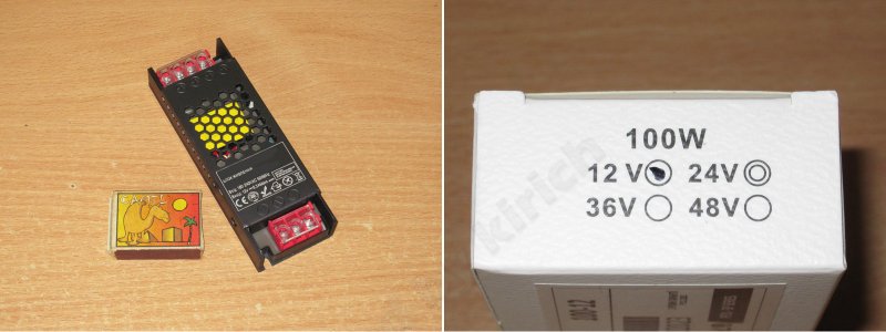
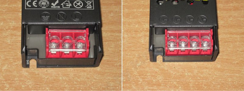
It connects via screw terminals and has a protective cover. There are four output terminals, two for each pole, which can be handy sometimes.
I forgot to take a photo, but there’s an issue with the cover. It was extremely difficult to remove. The reason is that it’s made of aluminum—or, judging by how it cracks at the bend, duralumin. Who thought it was a good idea to make a cover out of such thick, unsuitable material...
There are small fins on the bottom of the case (though “fins” is a bit of a stretch), which are more decorative than practical.
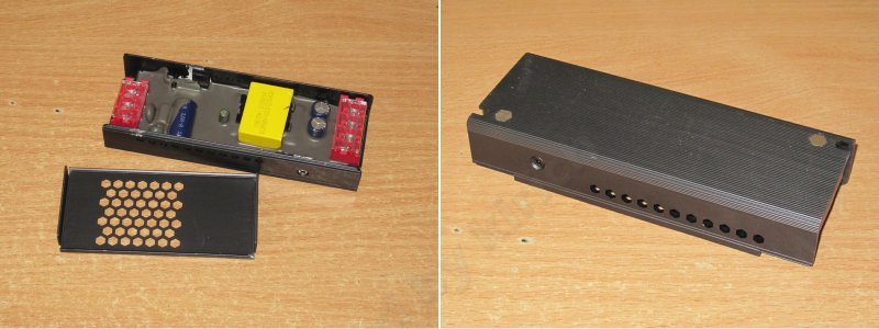
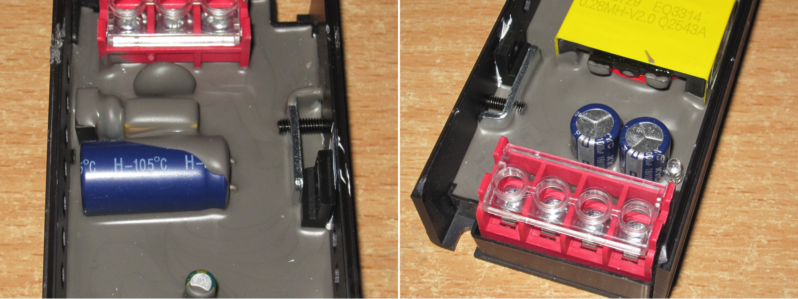
This power supply has a moisture-resistant design (not to be confused with waterproof). The components are pressed against the case through thermal paste. Overall, it’s a classic-looking, neatly made unit.
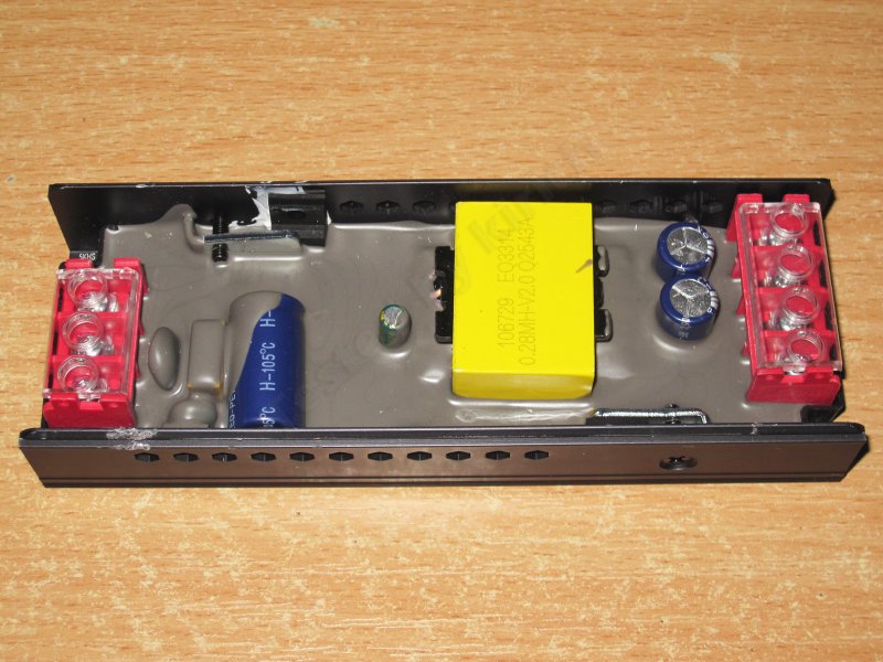
The input capacitor’s capacitance isn’t visible, and I didn’t feel like digging it out. The output capacitance is 1000 µF.
It also has a full input filter, including both a thermistor and a varistor, which are clearly visible under the potting compound.
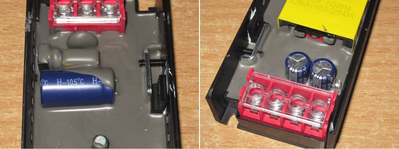
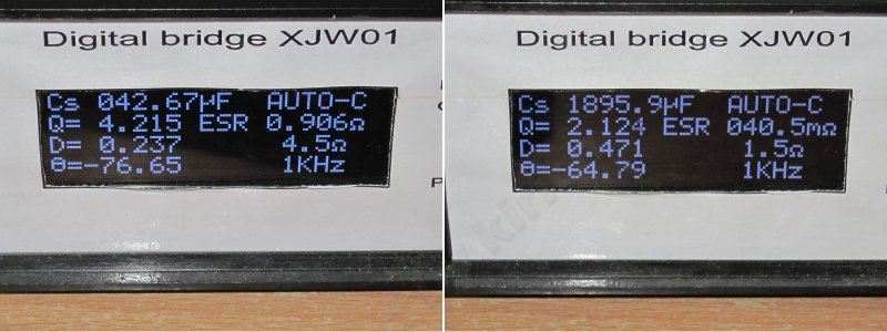
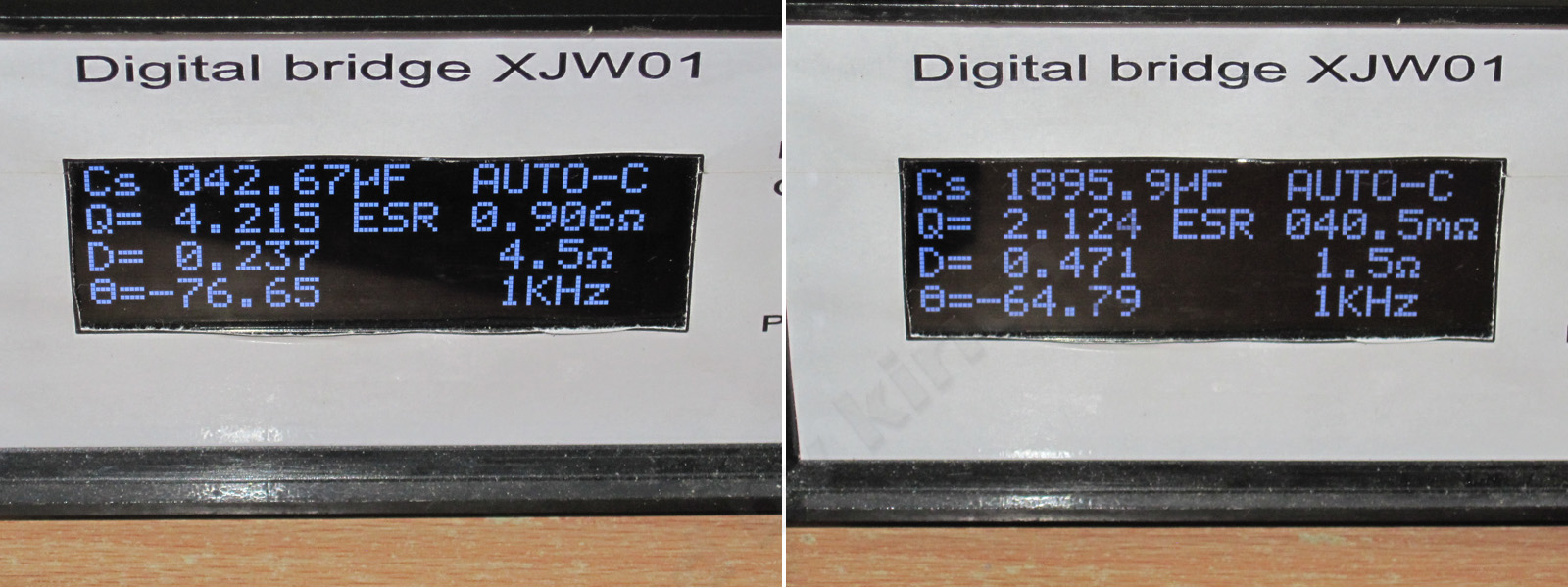
The input capacitor’s actual capacitance is just 43 µF, far too low for a 100 W model. The output capacitance of 1900 µF is also on the low side, and the ESR is rather high.
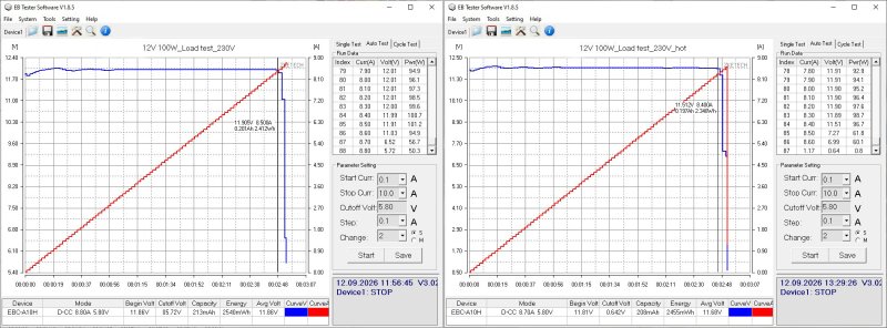
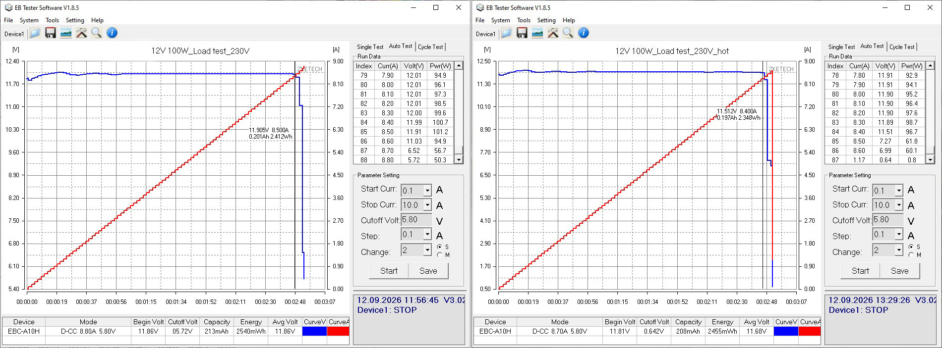
The protection is set very close to the maximum current, at around 8.4–8.5 A. I should note a very curious relationship between the output voltage and the load at the beginning of the range. I wonder why...
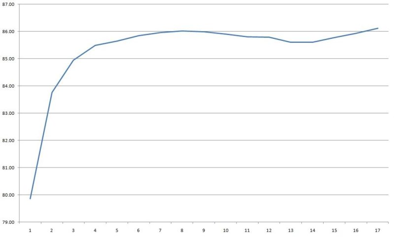
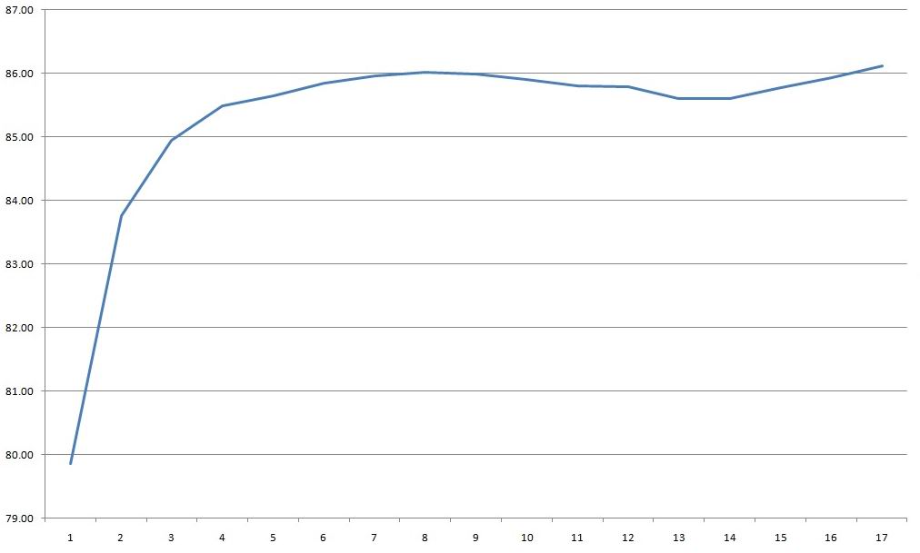
Efficiency was measured from 0.5 to 8.5 A in 0.5 A increments and came to around 86%.
Overall, not a bad result, but once again we have an unusual graph, with a bump at around 50% load.
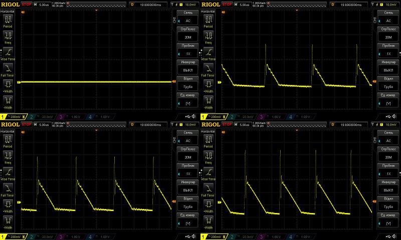
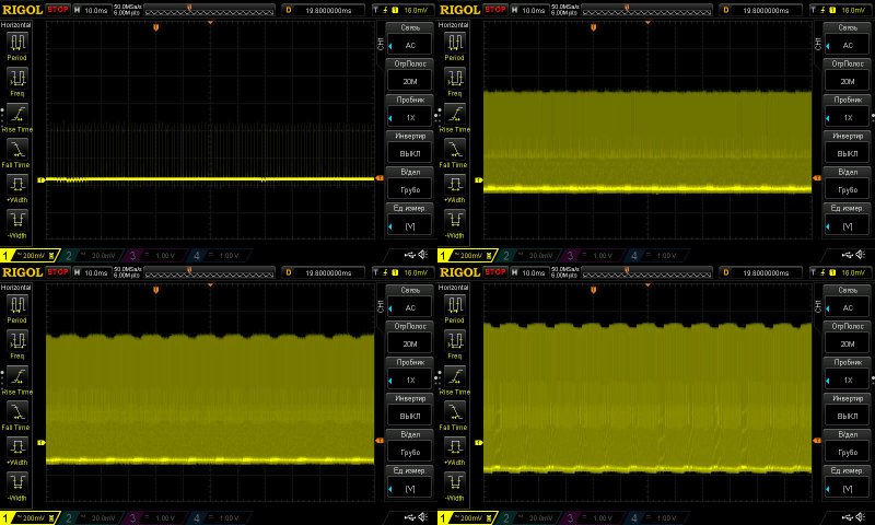
Ripple with no load and at currents of 2.5, 5, and 7.5 A.
This is a rather disappointing picture: 500–600 mV over most of the waveform and 1 V peak-to-peak. And what’s even worse, I’m almost certain the capacitors won’t last long under these conditions.
Against the overall background, the 100 Hz ripple is almost unnoticeable, of course, but this much ripple in the “overall background” isn’t good.
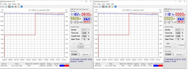
The load test was performed at currents of 4.2 and 8.3 A.
There’s essentially no relationship between voltage and warm-up, but if you look at the voltage graph at 8.3 A, you can see that the voltage drops. Look more closely, and you’ll notice that it first jumped up, then started dropping after the current was increased to 8.3 A.
In other words, the output voltage increases with load current, and the subsequent drop is caused by the power supply entering the mode just before protection trips.
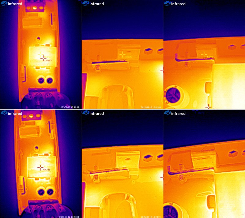
Component temperatures:
4.2 A — transformer 64°C, transistor 52°C, and diode assembly also 52°C
8.3 A — transformer 98°C, transistor 81°C, diode assembly 84°C.
That seems a bit high to me. There’s almost no headroom for a rise in ambient temperature, and considering that power supplies like these are sometimes installed in electrical panels, above suspended ceilings, and even in outdoor enclosures, I think the maximum current here is closer to 6.5–7 A.
Another 100 W model, rated at 12 V and 8.3 A, but this time in a sealed enclosure.
The specified input voltage range is 180–264 V, which is more appropriate for our mains supply.
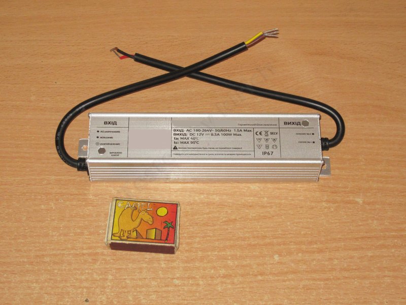
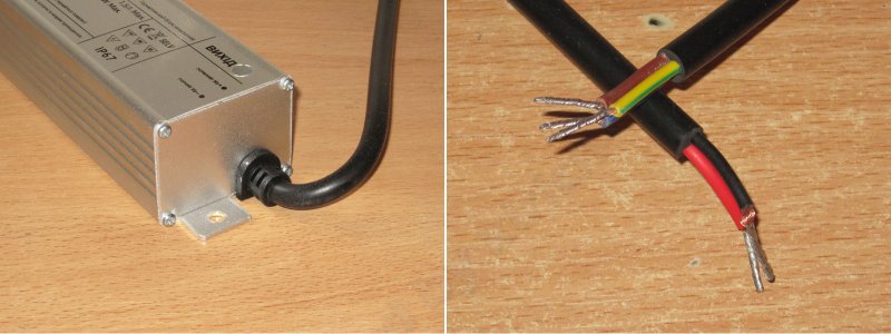
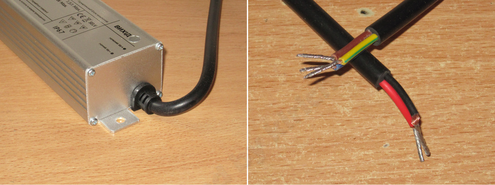
There’s not much to show here: end caps secured with self-tapping screws, wires with a sufficient cross-section—in short, nothing special.
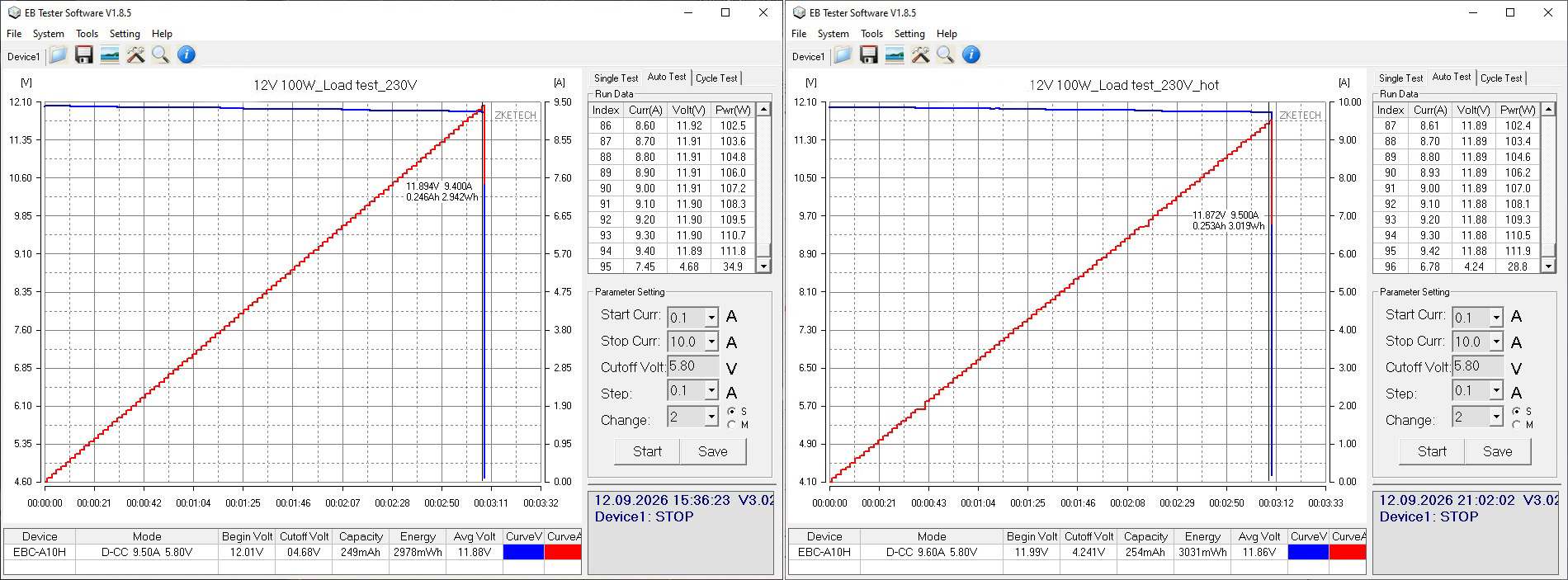
Protection is set to around 9.4–9.5 A, with no issues. There’s a slight voltage drop under load, which is perfectly normal since the measurements are taken after the output cable.
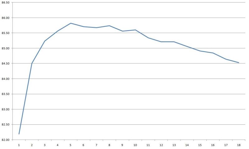
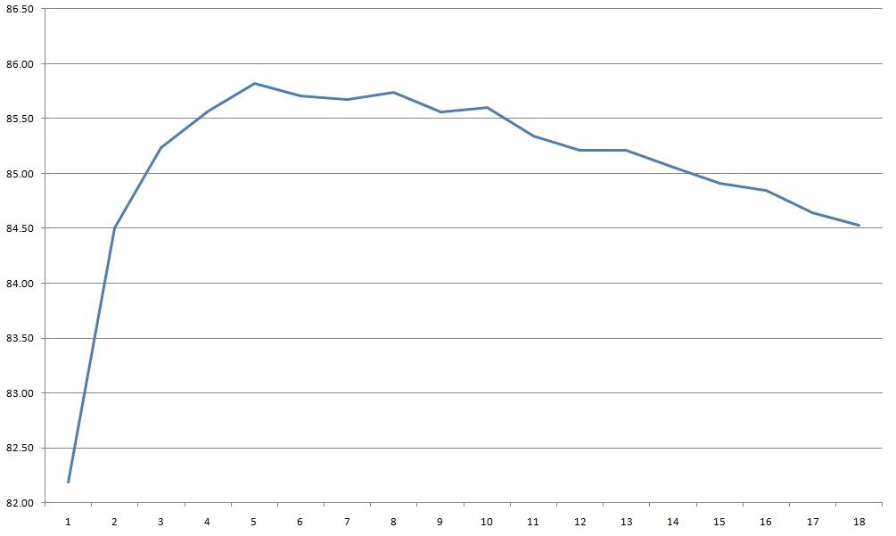
Efficiency was measured from 0.5 to 9 A in 0.5 A increments and came to around 85.5–86%. If it weren’t for the fairly typical efficiency—though it’s normal for this power level—I’d have guessed from the shape of the graph that it uses a synchronous rectifier.
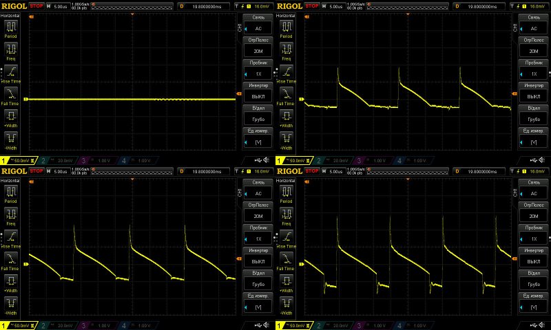
Ripple was measured with no load and at currents of 3, 6, and 9 A.
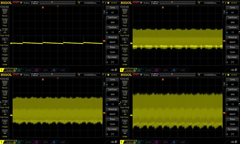
Surprisingly, the results here are noticeably better than with the previous power supply: around 130 mV over most of the waveform, with a peak-to-peak value of 220–230 mV.
I wouldn’t call the ripple low, exactly, but I can’t call it excessive either. It’s quite acceptable given the voltage and load current.
Even at 100 Hz, I wouldn’t say there’s anything bad going on. Yes, there’s a bit of ripple, but again, it’s not critical.
I have a strong feeling that this and the previous unit are two completely different power supplies, with their own circuit design quirks and made at different factories.
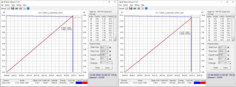
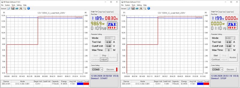
The load test was performed at currents of 4.2 and 8.3 A. I wanted to try 10 A, but changed my mind—I don’t want anyone accusing me of torturing the test subjects :)
There’s a slight negative relationship between voltage and temperature, but it’s only 20 mV.
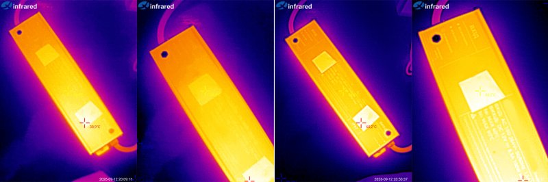
For the temperature test, two small pieces of electrical tape were stuck to the power supply’s case to ensure accurate temperature measurements.
At 4.2 A, the case warmed up to 39°C; at 8.3 A, it reached 60°C. In both cases, the hottest area was near the output end of the power supply.
It’s hard to say much here. Yes, it gets hot, and yes, it’ll burn your hand, but yes, that’s normal too.
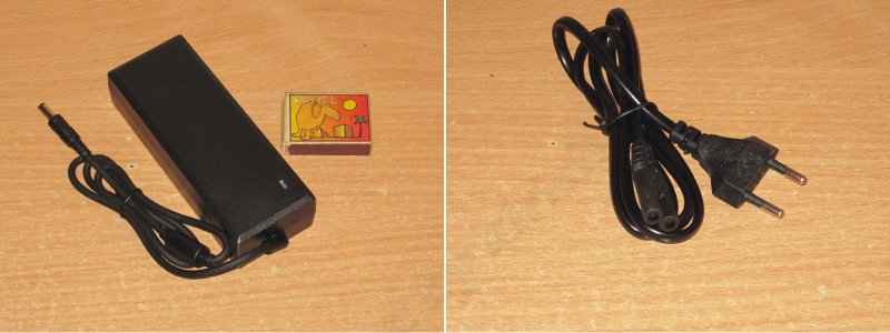
The most powerful power supply in the test is a desktop model rated at 120 W, or 12 V and 10 A.
The specified input voltage range is 100–240 V.
The package includes the power supply and a mains cable.
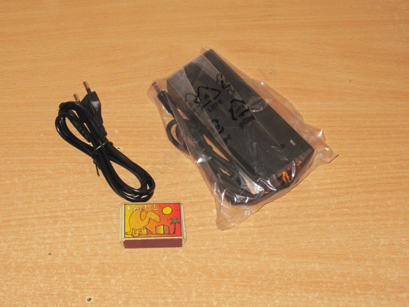
The case is relatively compact, especially for the claimed power output. That means either it uses a proper, expensive design—or the second option.
But what surprised me more was the cable. The connector is the usual figure-eight type; I honestly don't understand why they didn't use the standard "computer" connector.
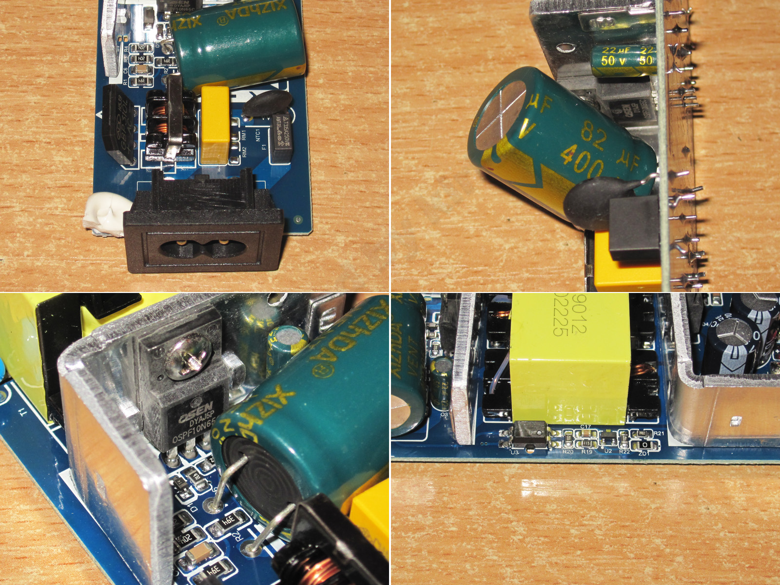
I opened it up. Nothing unusual, just another power supply. The transformer is rather small for 120 W, though.
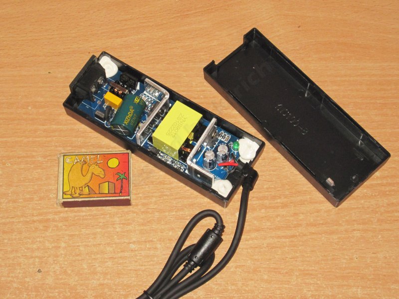
The board is neatly laid out, but I was even more surprised that they used this kind of mains connector after all. Both the case and the board could easily accommodate a standard—or, more precisely, more common—"computer" connector...
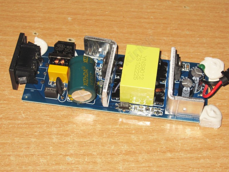
1. There is an input filter. No varistor, but that's not really critical; what's more important is that they didn't forget the thermistor.
2. The input capacitor is rated at 82 µF, which is already rather small for 120 W, even on a 230 V mains supply. I won't even get into operation at 100 V.
3. The high-voltage transistor is rated for 10 A and 650 V. That's basically fine here.
4. All the feedback circuit components are placed at the edge of the board, and you can see a protective slot under the optocoupler.
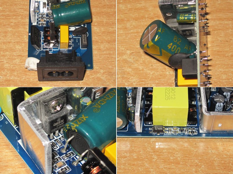
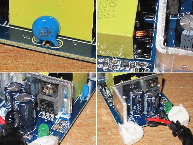
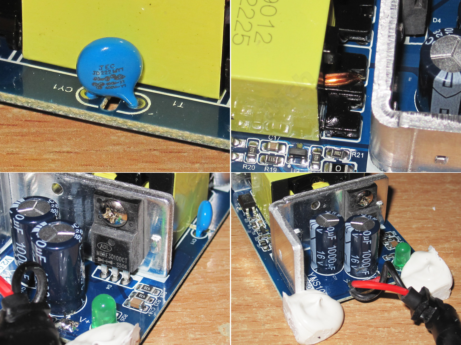
1. There is a Y capacitor, and judging by its appearance, I can say that all the power supplies in plastic cases shown in this article were made at the same factory.
2. The secondary winding consists of just a few relatively thick strands.
3. The output rectifier is a 30 A, 100 V diode assembly. Basically fine, as long as you don't let it overheat.
4. And just two 1000 µF capacitors for 10 A?
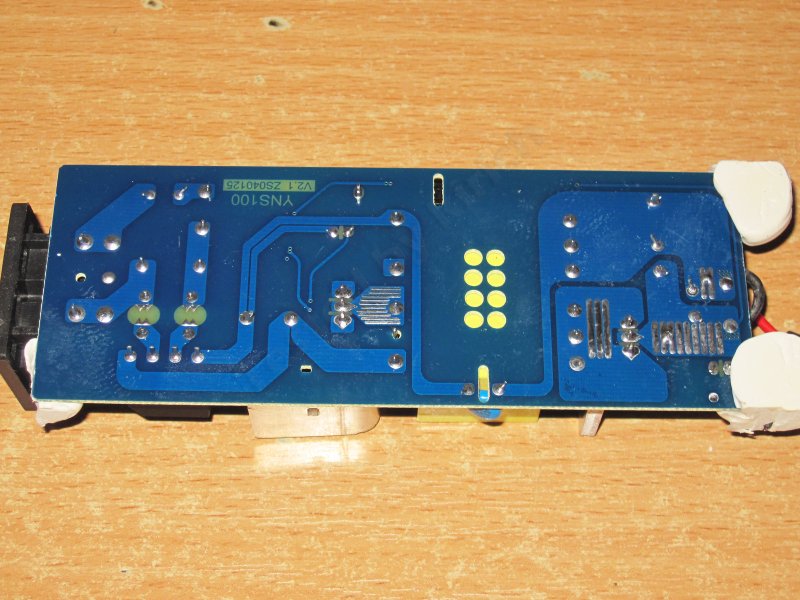
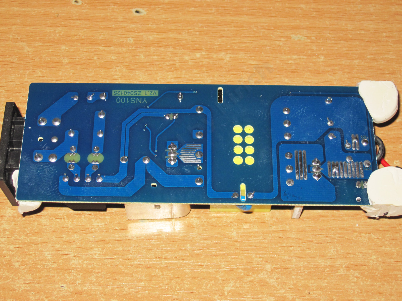
As with the previous similar power supplies, I have no complaints about the circuit board. It's a little dirty, but that happens—maybe the assembler was just taking lunch :)
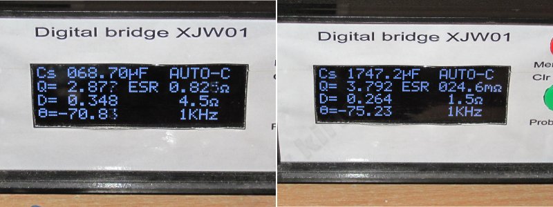
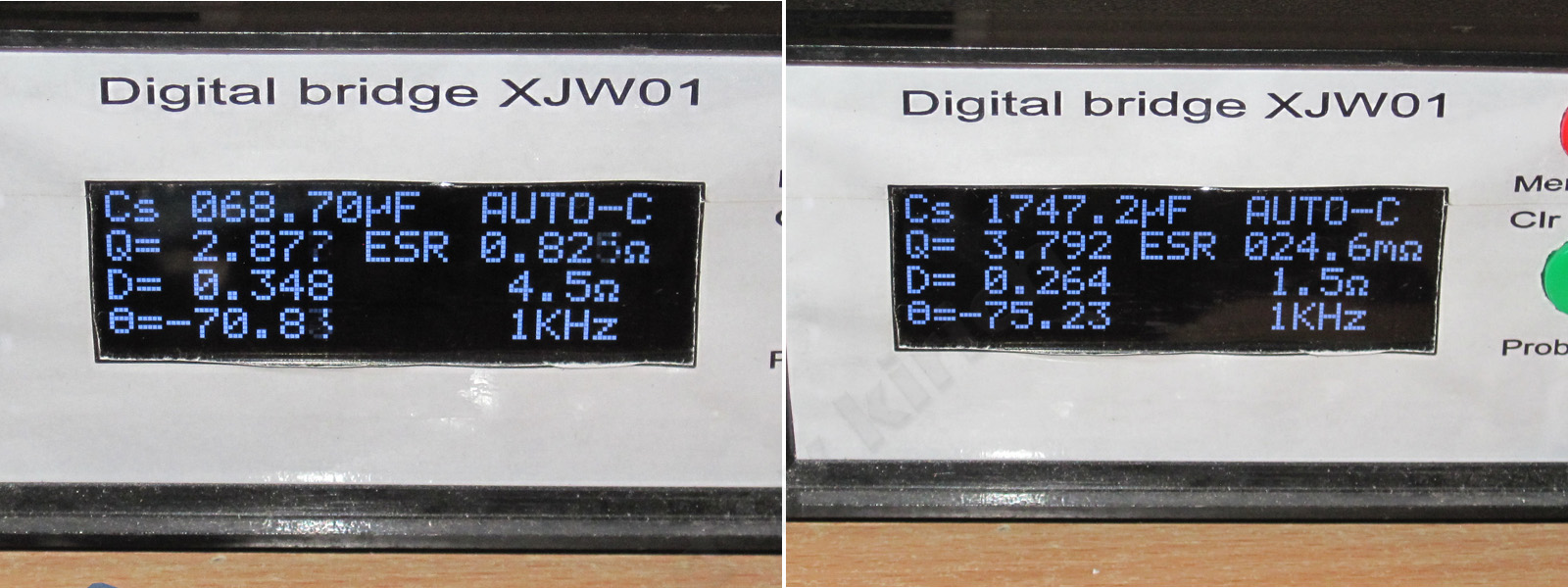
The input capacitor's actual capacitance is 69 µF, which was to be expected. The output capacitance is 1750 µF, but the capacitors are a little better than those in the 72 W version.
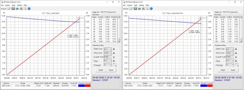
The overcurrent protection trips above the 10 A threshold, both when cold and when hot. A follow-up test showed that it trips at 10.6 A.
At 10 A, the output voltage drops by 0.65 V; essentially, the entire drop is across the output cable.
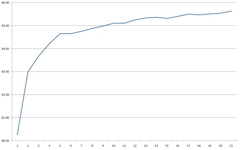
Efficiency was measured from 0.5 to 10.5 A in 0.5 A increments and came out at around 85–85.5%.
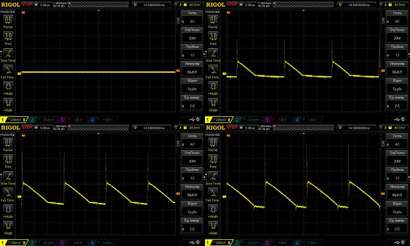
Ripple with no load and at 3, 6.5, and 10 A.
At maximum current, I measured about 400 mV of main ripple and 1 V including the "spikes". So, mediocre again—and I wouldn't say things are noticeably better at 6.5 A. The ripple is within acceptable limits, of course, but the question is whether it will start increasing over time, since the output capacitors are operating under fairly demanding conditions.
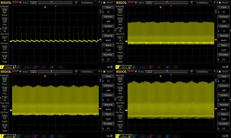
At low frequency, you can see a little 100 Hz ripple, especially at full power. The input capacitor is a bit undersized, but against the overall background, I wouldn't say the ripple is all that large.
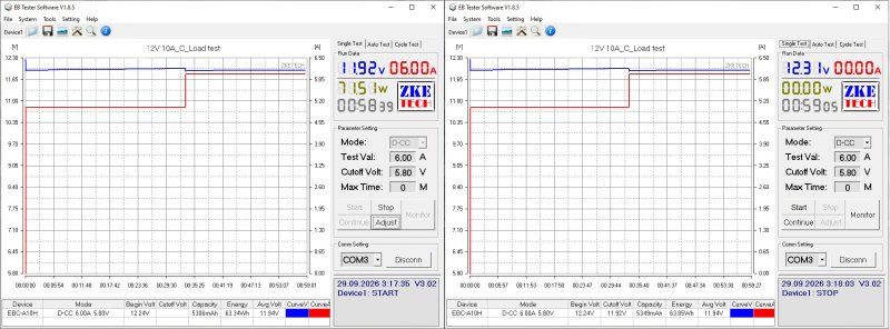
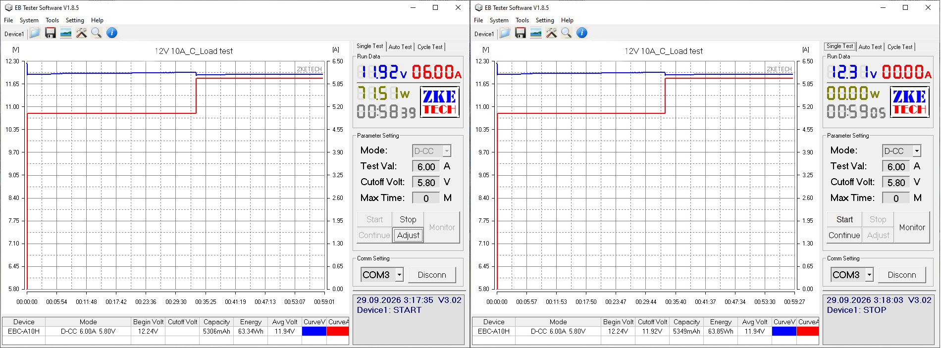
The load test was run in two modes: first at 5 A, or 50% load, and then at 6 A. I think you've already guessed why there's no test at 10 A.
The output voltage has a positive temperature coefficient of about 70 mV, which isn't critical.
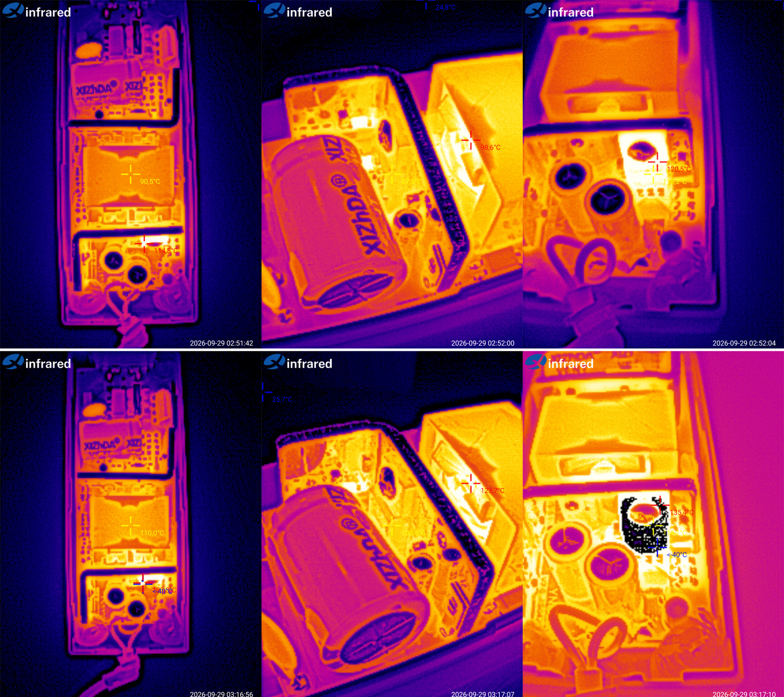
And of course, here's the thermal image.
5 A — transformer at 90 degrees, transistor at 87, and diode assembly at 120.
6 A — transformer at 110 degrees, transistor at 108. The diode assembly went beyond the thermal camera's maximum range, so we're seeing 135 degrees.
There's not much to comment on here. It's clear that at 5 A the power supply is already struggling, while at 6 A it overheats—and that's at room temperature. There's obviously no thermal protection, so I see two possible outcomes if you run it at full current. First, the transformer starts to saturate and the overcurrent protection trips, at least for a while. The second possibility is less optimistic.
Conclusions.
1. 36 W, 3 A adapter. The actual maximum power is 30 W; above that, the protection trips. The actual continuous power is closer to 20–25 W. It's a fairly basic unit, apparently inexpensive. Ripple is mediocre, but it should work, especially since it uses a dedicated chip and most likely has thermal protection.
2. 36 W, 3 A desktop power supply. This one looks clearly better than the previous one. Ripple is slightly higher, and its thermal performance and power output are adequate at room temperature. However, the protection current is set about twice as high as it should be, which could have serious consequences since there is no thermal protection.
3. Sealed, 36 W, 3 A. The protection current is set correctly, and there are no issues with heating either, but output ripple is quite high, around 500 mV, and the low-frequency waveform isn't very pretty either.
4. Desktop, 72 W, 6 A. The construction is decent and neat. The protection current is 7.4 A, which would be fine if the actual maximum continuous current weren't only about 4.5 A. Ripple is around 400 mV, so the only real complaint here is that the rated power is overstated by a factor of one and a half.
5. Weatherproof, in an enclosure, 100 W, 8.3 A. I really like the build: neat, attractive, and pleasant to hold. The protection is set right on the limit, but that's actually a good thing for this unit, since it would simply overheat under a heavier load. There is one caveat regarding heat, related to the typical use case: power supplies like this often have to operate over a wider temperature range, so I wouldn't load it beyond 75–80 W. And the ripple at maximum current is around 600 mV—too much.
6. Sealed, 100 W, 8.3 A. No complaints about the build, the protection current is set correctly, and, surprisingly, ripple is within spec. Heating is also within normal limits. There's not much to criticize, really; it's a reasonably decent 100 W power supply.
7. Desktop, 120 W, 10 A. I might even have praised this one: it's neatly assembled, the protection is set to 10.6 A against a rated 10 A, and ripple is generally within the normal range for a budget unit. But the fact that its actual power is only about 60 W, despite being rated at 120 W, wipes out all its positive points.
The conclusions give a brief summary; for the details, it's best to refer to the full review.
I'd also point out what almost all the power supplies shown here have in common: ripple is mostly average or noticeably above average, and the power rating is often overstated, leading to overheating. At the same time, the assembly is fairly neat and the circuit board is well thought out, although the components are often budget-grade and the capacitors are frequently undersized.
It's worth noting, though, that if you're powering something like LED strips, ripple isn't critical. But power supplies are versatile devices, and they're often bought for more than just that. LED lighting does, however, bring its own issues to light.
The ripple situation was interesting, actually. I finished checking everything, then went through the materials and realized that the ripple was noticeably high rather often. But I'd tested other power supplies just shortly before that, and everything had been fine. My first thought was that maybe I'd accidentally tested the earlier ones with the 1:10 probe attenuation enabled. I didn't want to take any chances, so I grabbed one of the earlier units at random, hooked up the oscilloscope, confirmed everything was fine, and relaxed.
To keep up with new posts on the blog, I recommend following me on Instagram, where I'll post notifications about every new article and maybe write about something interesting now and then: link to my account
You can also subscribe to updates and new articles on the Telegram channel - https://t.me/KirichBlog Note that discussion of reviews and articles is enabled on the channel, along with general chat. I recommend it.
A note: to avoid any accusations, and as agreed with the project sponsor, the labels on all the units under test have been removed. Any resemblance to particular brands is coincidental. Otherwise, I promise this review will be as unbiased as possible—as are all my reviews.
Also, remember that you may use material from this blog only with the author's permission and with an active link to the original article.
As I mentioned, there will be seven models, arranged in order of increasing rated (not necessarily actual) power.
First up: a "wall outlet adapter" style unit, rated at 36 W, 12 V, 3 A.
The stated input voltage range is 100–240 V.
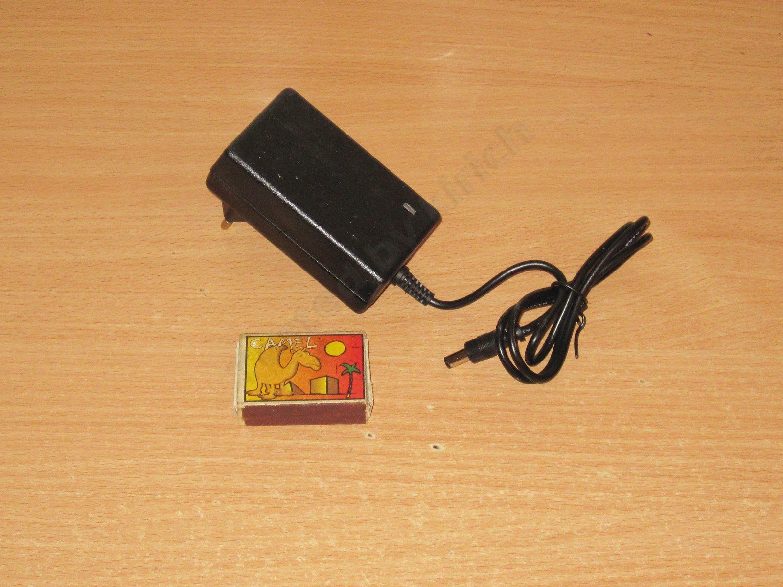
Inside, it's a fairly typical low-cost design, though I should point out that it does have an input filter, even if it's just a choke.
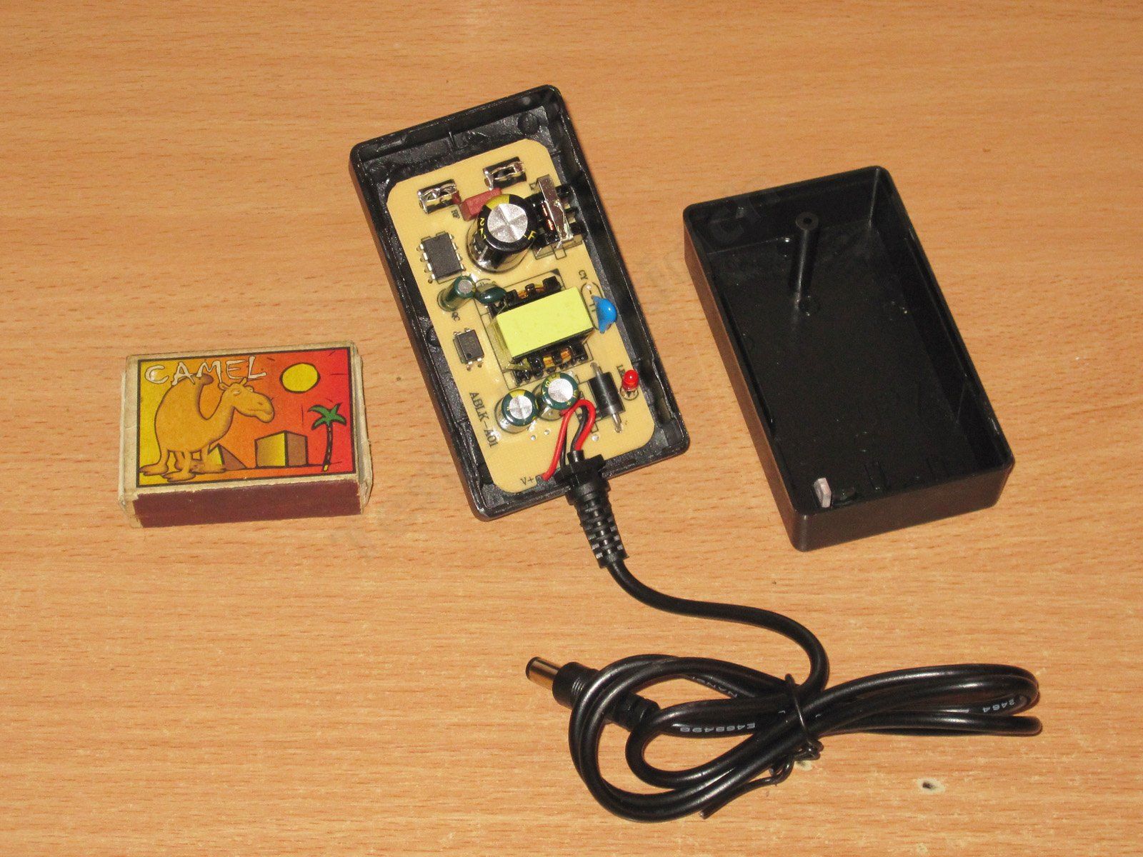
The circuit board is neatly laid out. This is pretty much the classic design for low-cost power supplies.
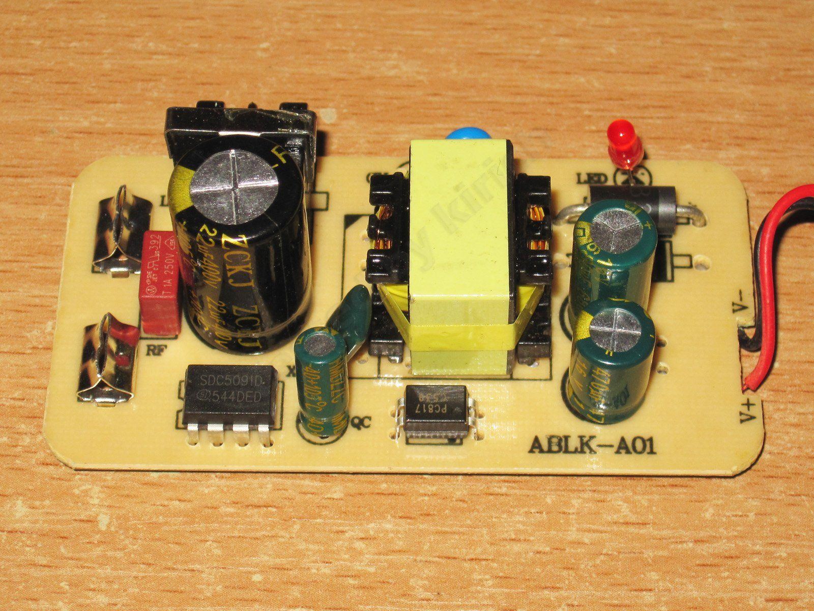
1. It uses an SDC5091 chip, designed for power supplies rated at 24–30 W. Having a chip like this is a plus, since they usually include overtemperature protection. But this is a 36 W unit, while the chip is rated for 30 W.
2. It has a Y capacitor. That's good.
3. There's a single output diode, a typical 3 A, 100 V part.
4. The output has a pair of capacitors, 680 + 470 µF. An odd combination, but that's a minor detail.
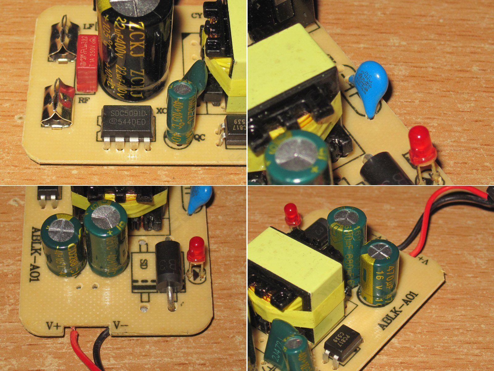
The underside is clean, if a little sparse, but that's normal with chips of this type. The feedback is simply through a zener diode, so the output voltage will probably fluctuate a bit.
The clearance between the Y capacitor's leads is very tight.
The input capacitor's actual capacitance is about 19 µF. That's just about enough for a standard 230 V mains supply, and too little for the stated input range starting at 100 V.
The total output capacitance is about 1000 µF, which is fine.
As expected, the protection kicked in at around 2.5 A with the power supply cold, and at 2.6–2.7 A when hot. So we won't be getting the rated 3 A. Under overload, the protection gradually reduces the output voltage depending on the current.
Efficiency is around 84%, which is normal for low-cost units.
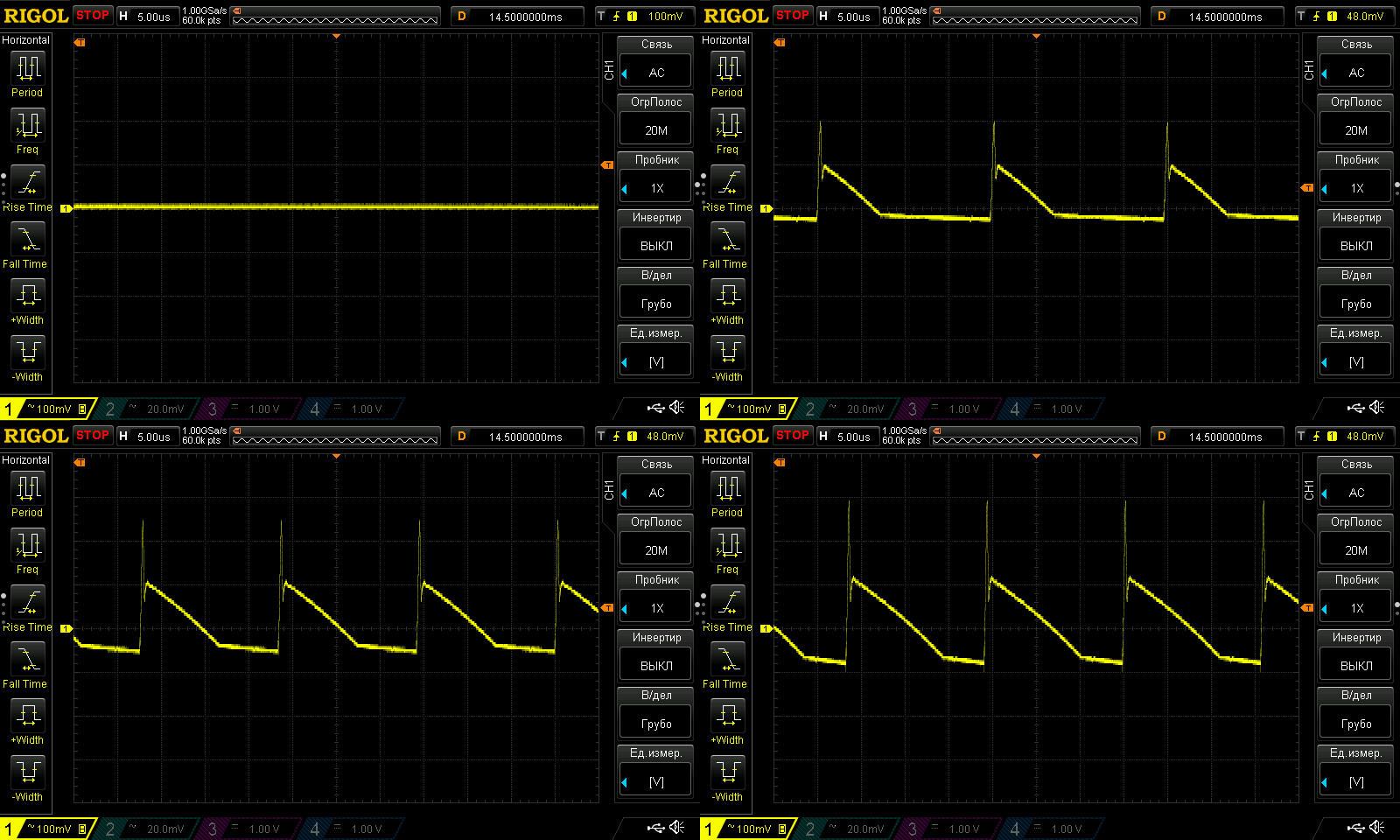
Since we won't get 3 A, I captured the waveforms with no load and at currents of 0.7, 1.4, and 2.1 A.
Well, this is pretty much what you'd expect: about 200 mV for the main component and 400 mV peak-to-peak. Typical results for power supplies at the low end of the price range.
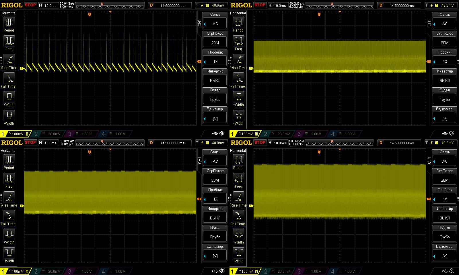
The first waveform suggests that the PWM controller has a "green mode," but the power supply was quiet with no load.
Otherwise, the results are typical too.
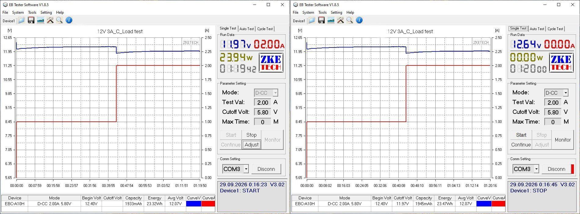
The load test was run in two modes: 1 A and 2 A.
Note that the graph already shows a positive relationship between voltage and temperature. "Positive" doesn't mean "good" here; it means the voltage rises as the unit heats up or the load increases.
As a result of heating, the voltage rose by 0.24 V. This is due to the simple implementation of the feedback circuit.
Key component temperatures:
1 A: transformer 64°C, PWM controller 71°C, output diode 79°C
2 A: transformer 103°C, PWM controller 112°C, output diode 130°C.
As the thermal image shows, even 2 A is too much for this power supply to handle continuously. The temperatures of all the main components are close to their maximum, and that's at normal room temperature. So the actual output current of this model is closer to 1.6–1.8 A.
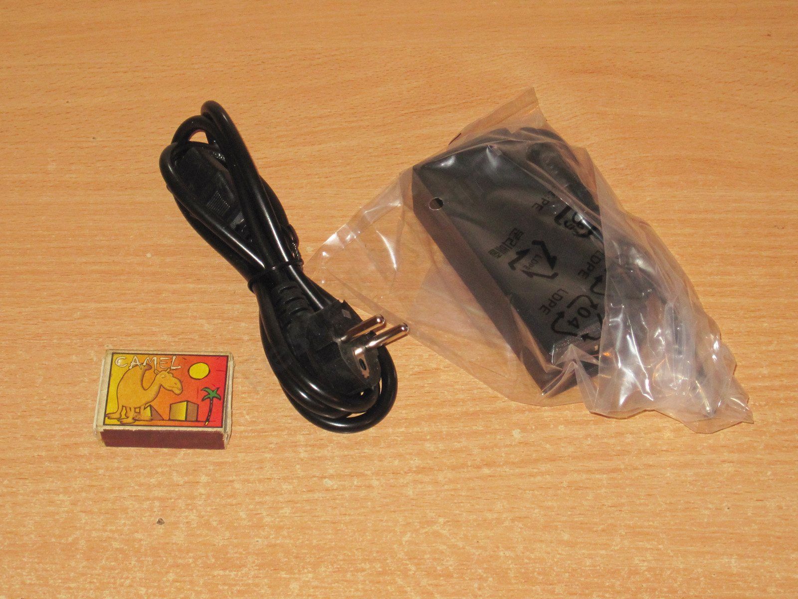
The second model is a desktop version, rated at the same 12 V, 36 W, 3 A.
The stated input voltage range is 100–240 V.
This one comes with a cable as well as the power supply—a standard “computer” power cable, which is handy..
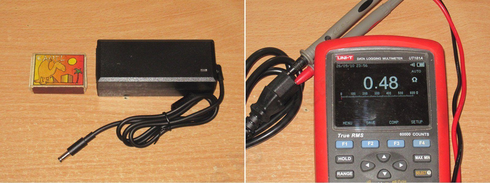
It looks pretty good. I like that the output cable exits at an angle; that can be genuinely convenient sometimes.
The mains cable resistance is about 0.5 Ω. That’s not exactly good—higher-quality cables are closer to 0.15–0.3 Ω—but I wouldn’t call it bad either; there are much worse ones out there.
The “guts” here are completely different from the previous model. It feels like there are about twice as many components :)
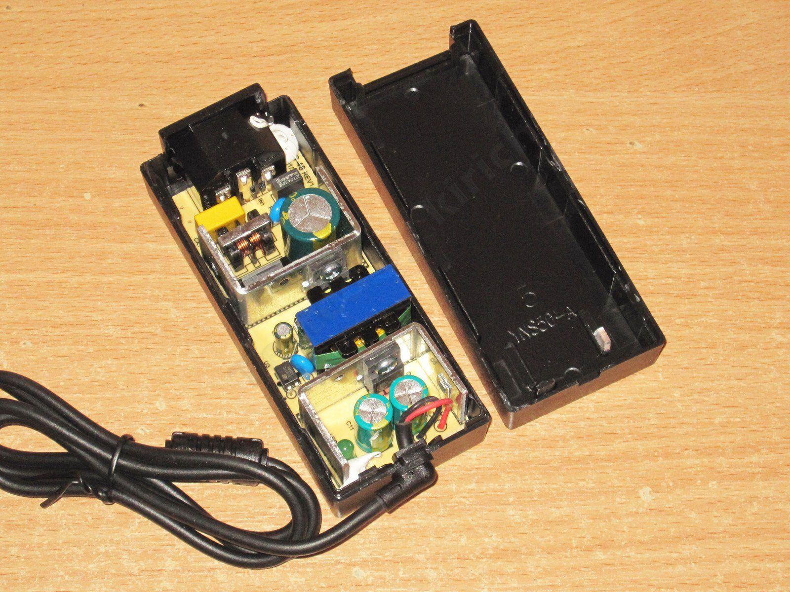
There’s an input filter, a pair of decent heatsinks, and a transformer that’s larger than the one in the previous model.
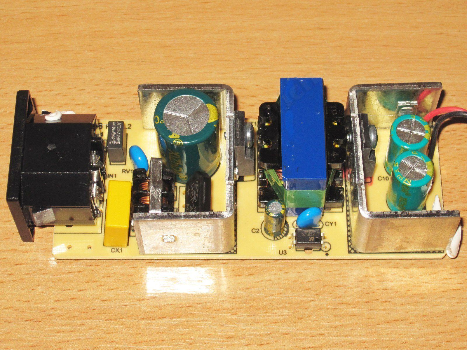
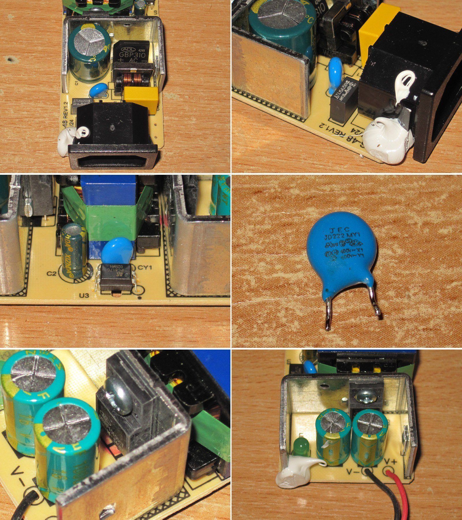
1. The only thing missing from the input filter, I think, is a thermistor.
2. They did fit a varistor, rated for 470 V peak.
3, 4. The Y capacitor’s leads are surprisingly close together. I even desoldered it to check, because I was sure it was an ordinary high-voltage capacitor, but no—the markings confirm it’s a Y capacitor. Y capacitors usually have their leads spaced about 1.5–2 times farther apart to meet safety requirements.
5. The output diode assembly is rated for 10 A, 100 V, which is perfectly adequate for this SMPS.
6. There are two 1000 µF, 16 V output capacitors, which is also fine.
The board looks very neat, and protective slots have been cut in the “tight” areas, so I have no complaints here.
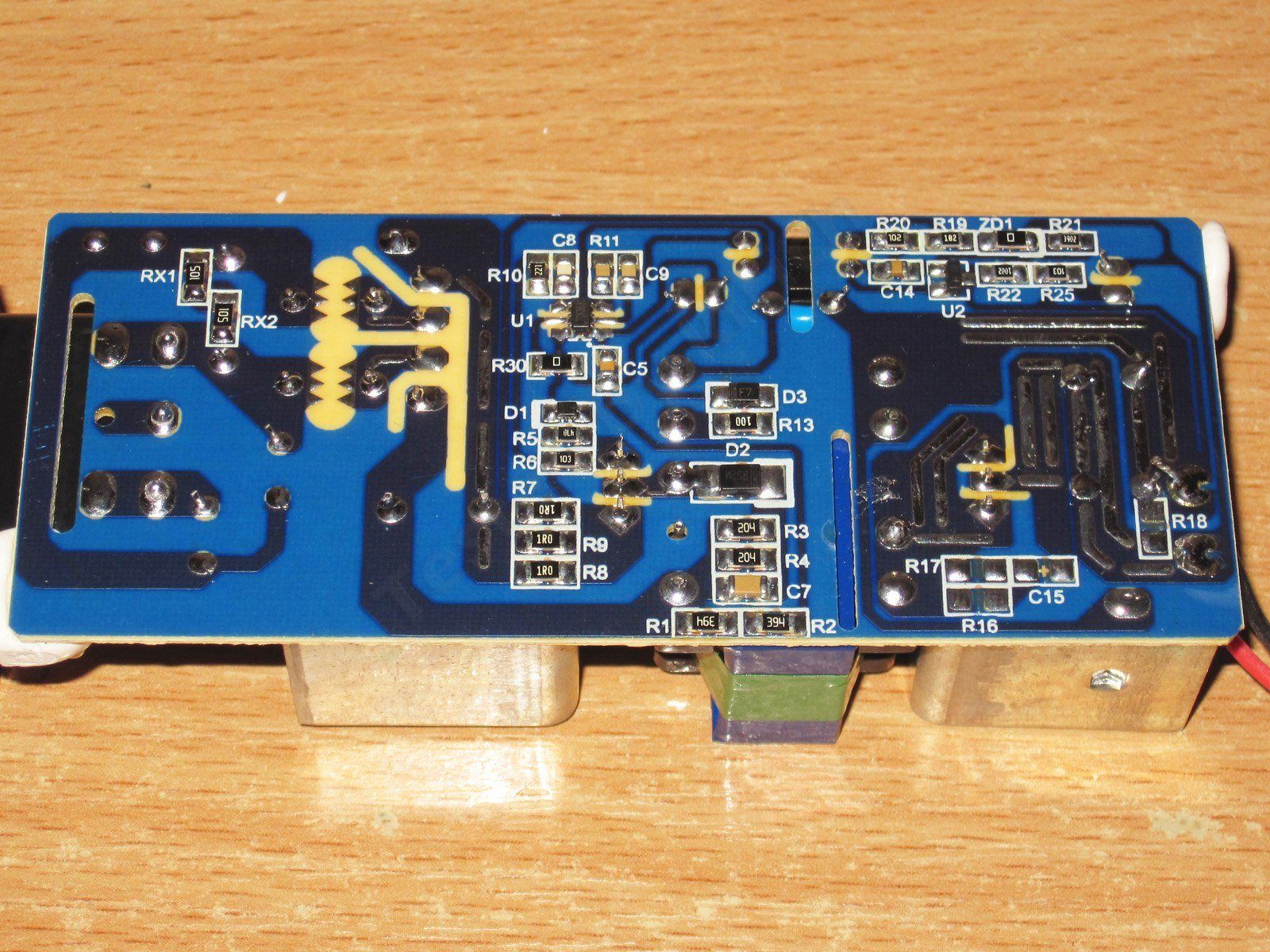
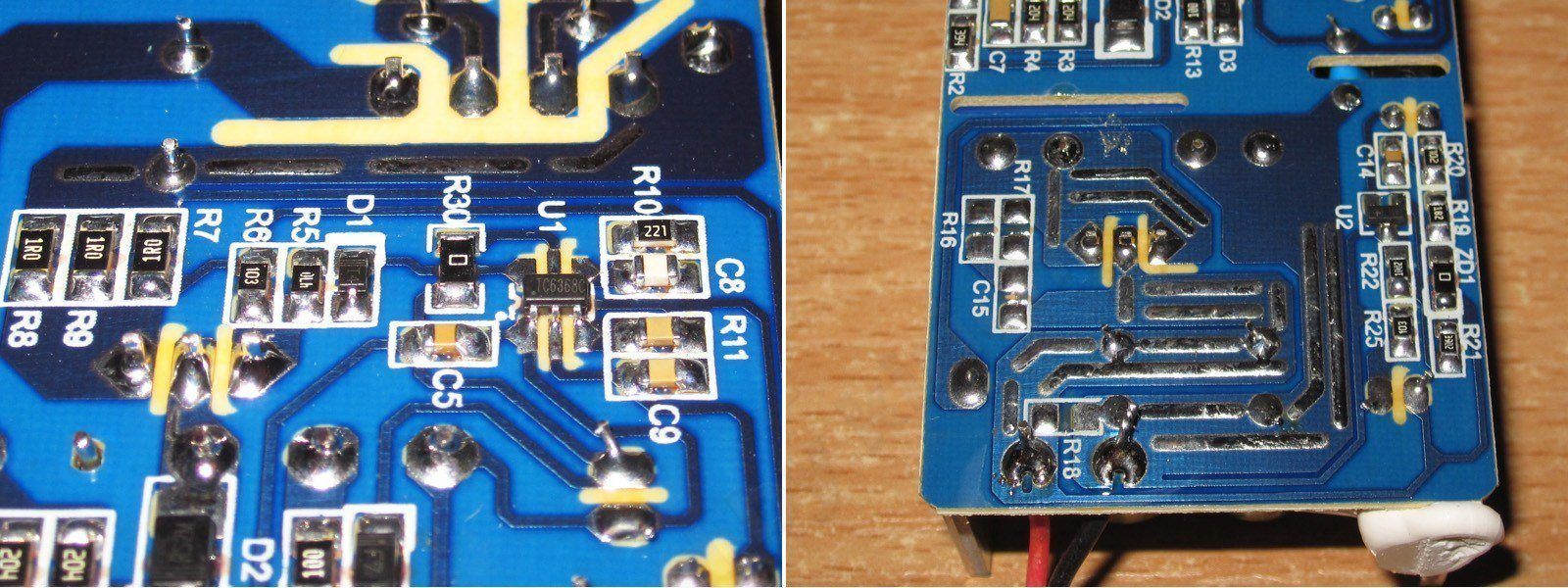
The PWM controller is a TC6368C. There’s no thermal protection, of course, which is expected, but I’ll note that the board is laid out properly, with solder added to reinforce the copper pours in high-current areas.
The actual input capacitor is 38 µF, and the output capacitors total 1800 µF.
For the upper end of the 230 V mains range, 38 µF is enough; for the lower end, it’s too little, unless you reduce the load power.
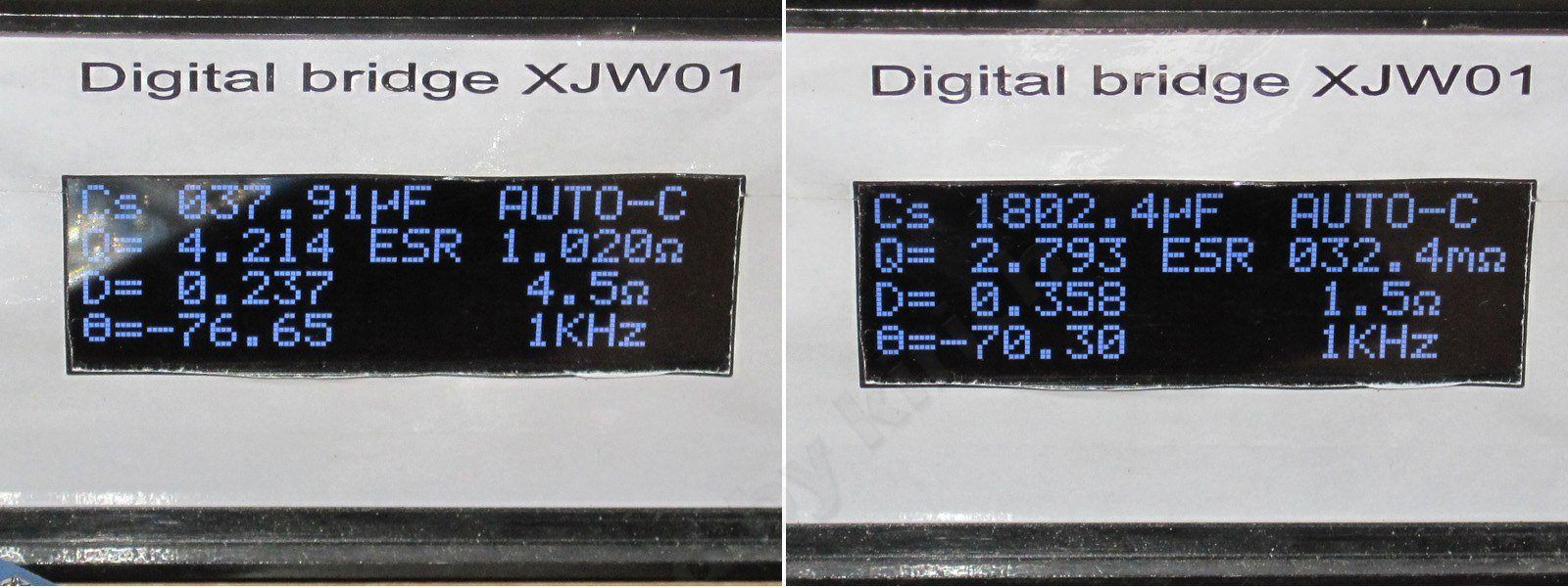
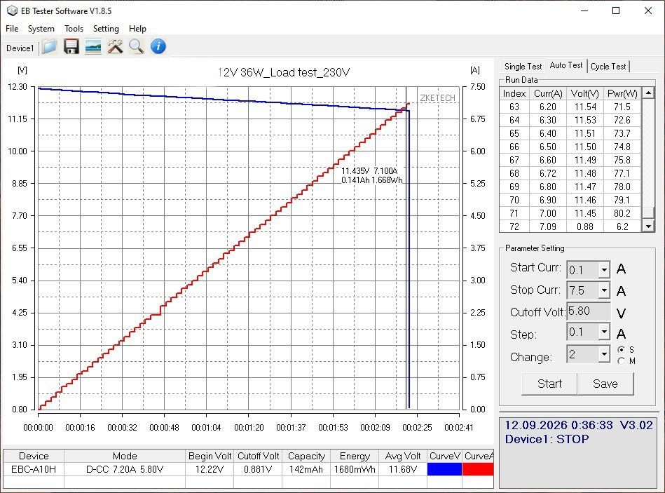
The protection threshold is ridiculously high—over 7 A, despite the stated rating of 3 A....
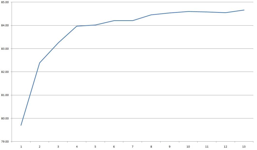
Efficiency across the 0.3–3.9 A range was about 84–84.5%; each division on the scale at the bottom represents 0.3 A.
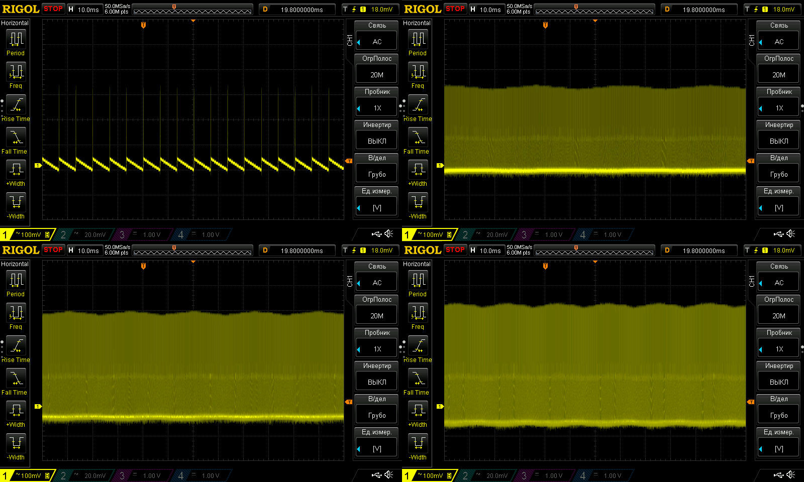
Ripple with no load and at currents of 1, 2, and 3 A.
It’s 250 mV for the main ripple and 500 mV including the “spikes.” That’s arguably tolerable for an inexpensive power supply, but judging by its appearance, this one isn’t all that budget-friendly, so they could have done something about it.
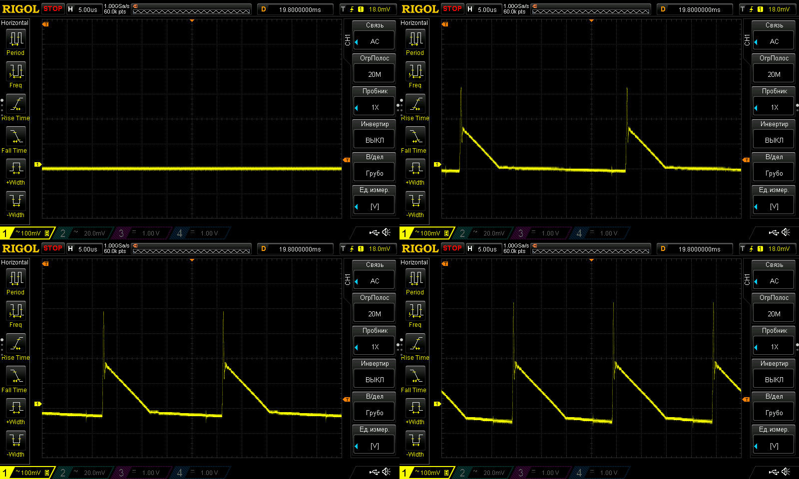
At low frequency, you can see the “green mode” operating with no load. The 100 Hz ripple is noticeable under load, but that’s about it—it gets lost in the overall noise.
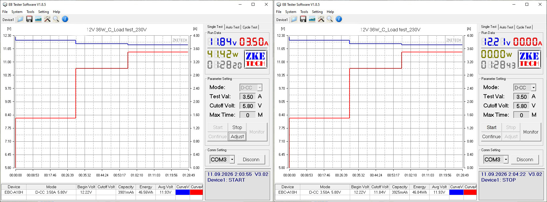
The load test was run in three modes, at 1.5, 3, and 3.5 A.
The power supply has a slight negative voltage drift as it warms up—just 10 mV.
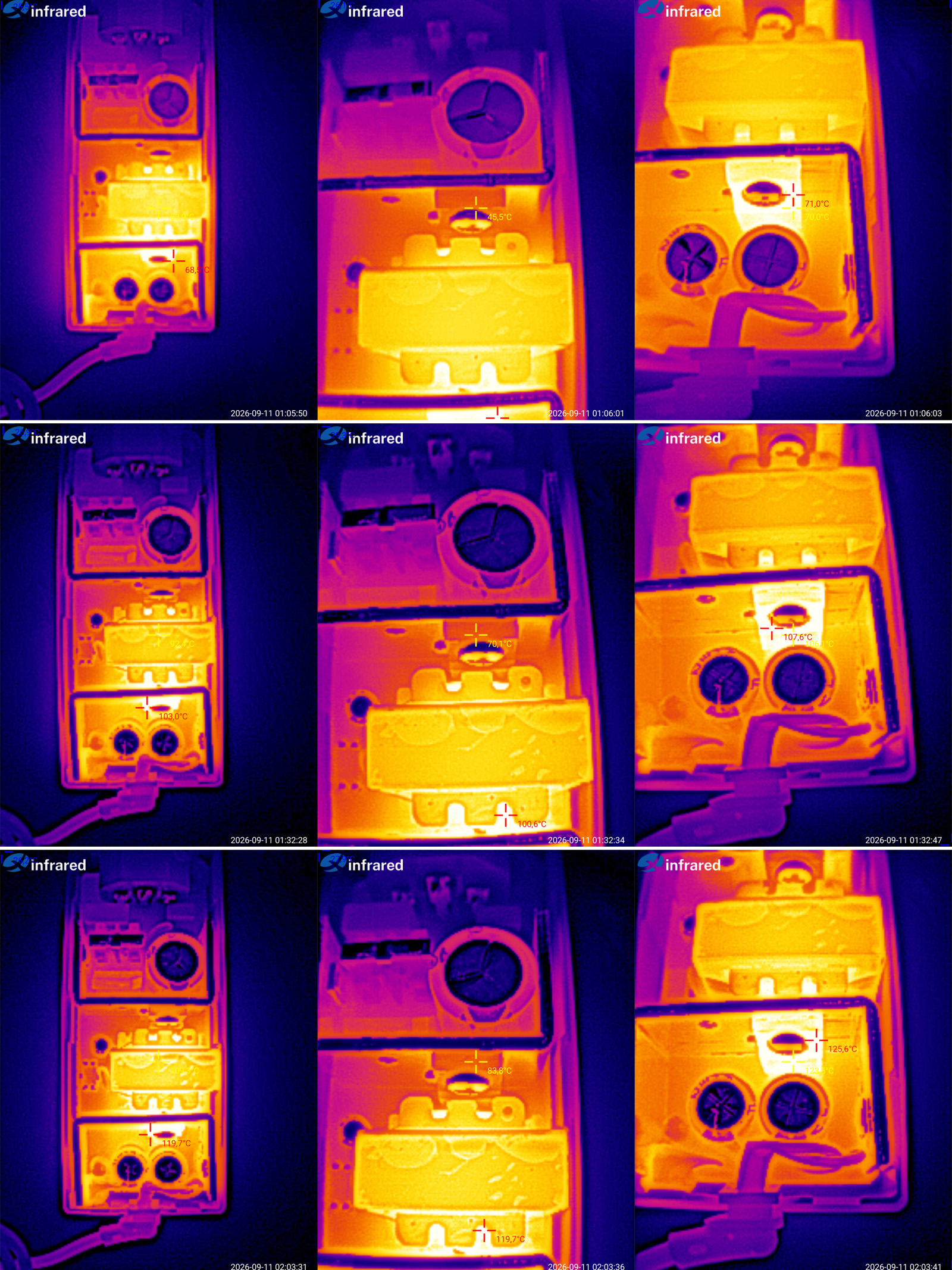
And now for the temperatures of the main components.
1.5 A — transformer 64 degrees, transistor 45, diode assembly 71 degrees.
3 A — transformer 92 degrees, transistor 70 degrees, diode assembly 108 degrees.
3.5 A — transformer 109 degrees, transistor 84, diode assembly 126 degrees.
It can deliver its rated 3 A with almost no trouble, but judging by the temperatures, I’d say it’s running pretty close to the limit, i.e. almost no headroom for ambient temperature.
That said, I should note that the heating can even be called well balanced, and there is some headroom for the high-voltage transistor to heat up.
The only thing that really concerns me is the very high overcurrent protection threshold and the lack of thermal protection—the issue is specifically how the two are related.
The third power supply is rated at 36 W, 12 V, 3 A, but this time it’s a sealed model.
The input voltage range is “narrow at the top”: 180–264 V.
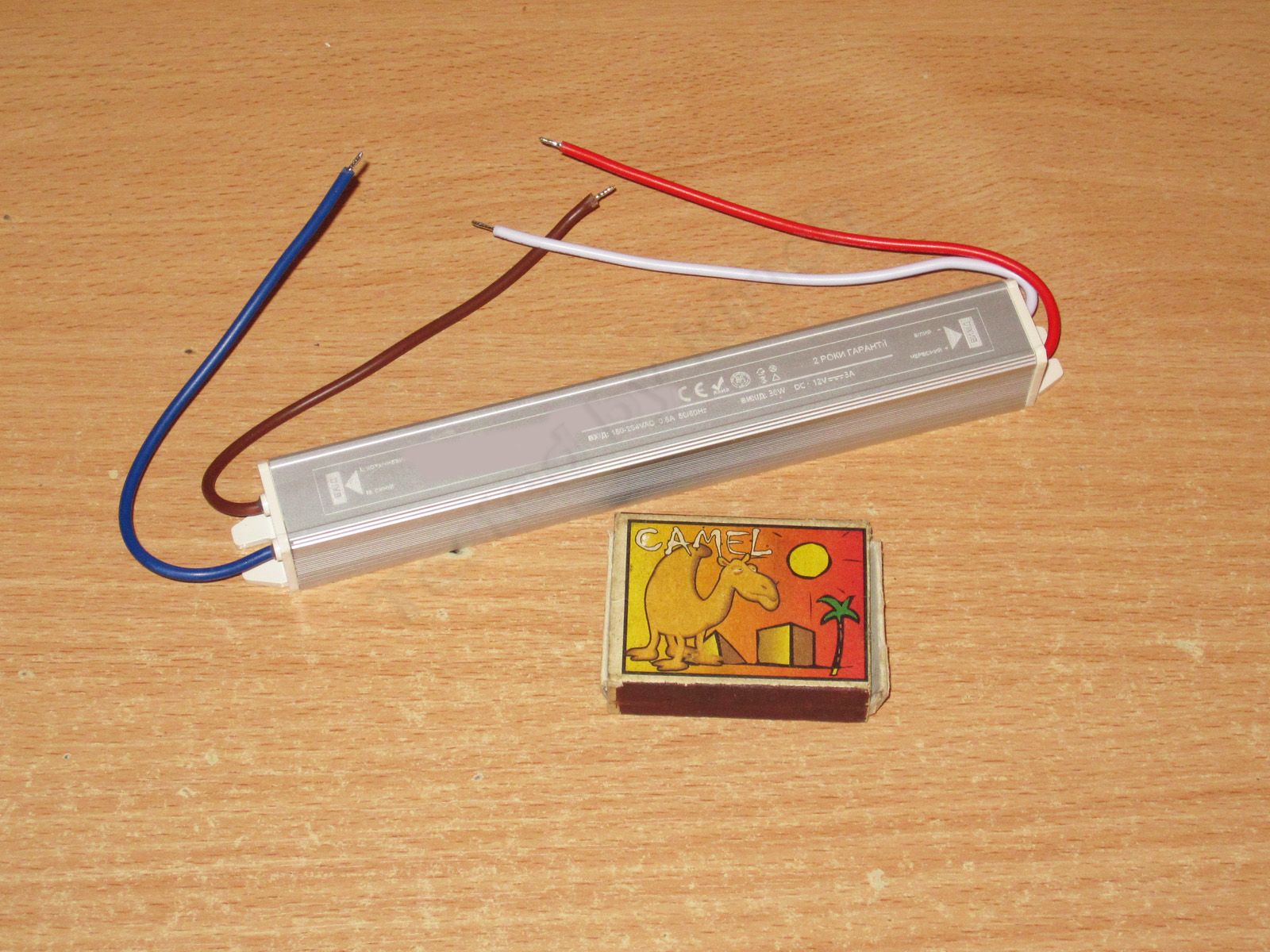
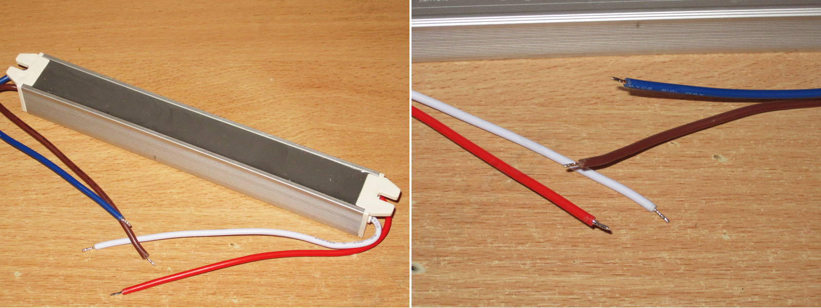
As for the construction, it’s the usual design: a U-shaped aluminum channel with a long, narrow circuit board inside, potted with compound. Given the relatively low power, all the heat is dissipated through the compound alone.
I wouldn’t call the wires thick, but on the other hand, the load current here is low, so it’s fine.
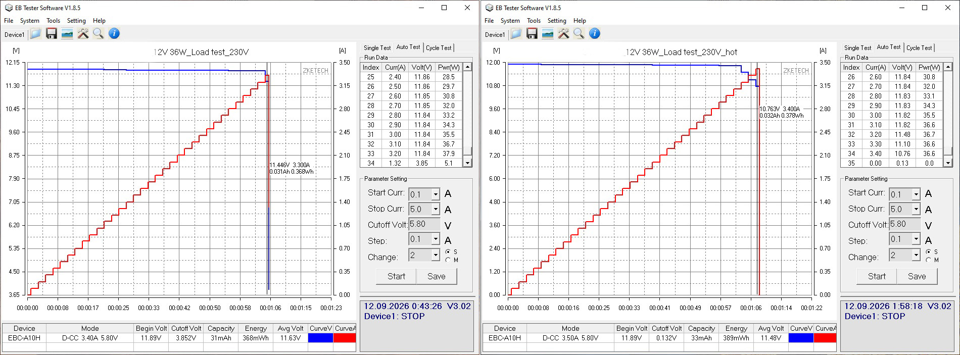
Unexpectedly, the overcurrent protection is even set correctly, at about 3.3–3.4 A depending on the case temperature.
There’s a slight negative relationship between output voltage and load, mostly due to voltage drop in the wires.
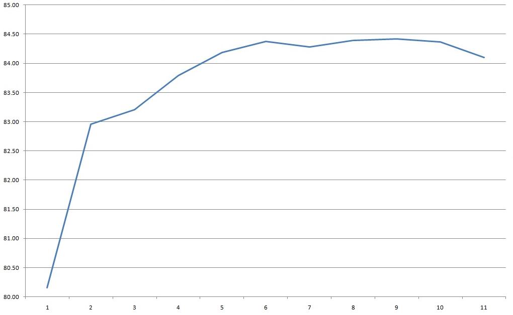
Efficiency is about 84%, measured from 0.3 to 3.3 A in 0.3 A increments.
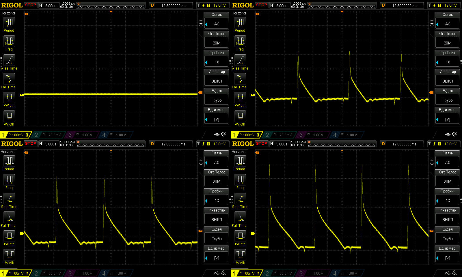
Ripple with no load and at currents of 1, 2, and 3 A.
Usually, when you measure ripple after the output wires, the “spikes” have a smaller amplitude, but that didn’t really help much here.
So the main component came out to around 300–400 mV, with a total amplitude of 600 mV. That’s quite a lot; I’d guess there’s a single ordinary capacitor of around 1000 µF on the output.
At low frequency, the picture is even worse. Judging by the ripple pattern, it may be caused by the way the PWM controller operates, but either way, it doesn’t look very good. I actually came across something similar recently, with one difference: although it looked very much the same, the total amplitude there was around 80–90 mV, while here it’s 700–800 mV, which is obviously disappointing.
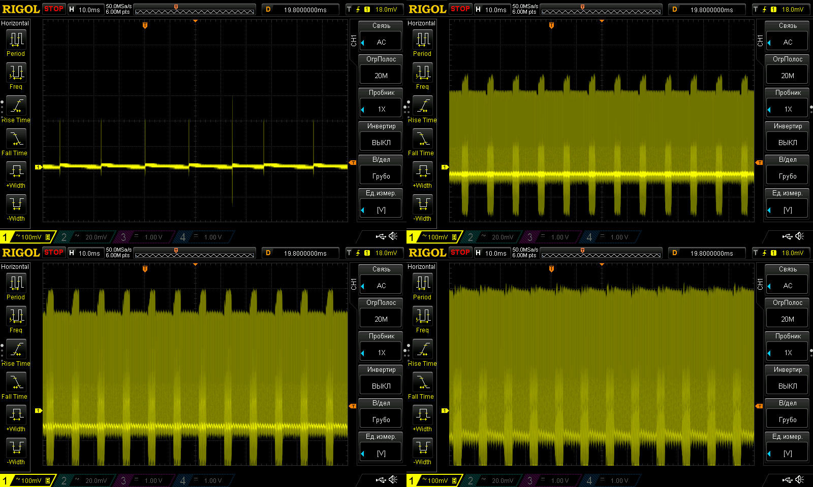
The load test was performed at 1.5 and 3 A. It showed that output voltage does not depend on temperature, within the measurement error.
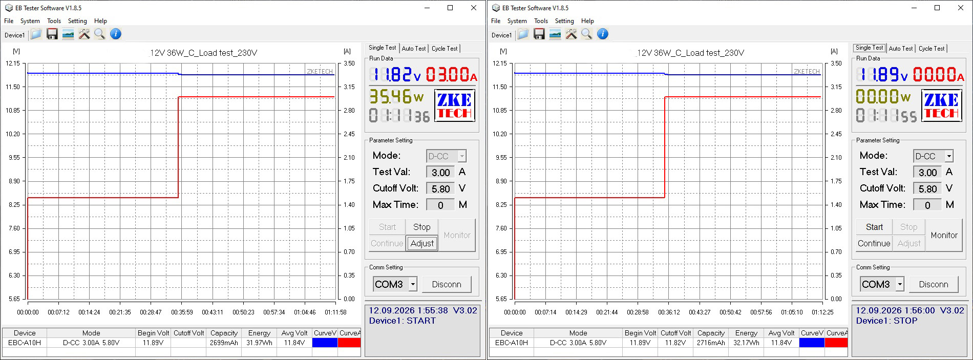
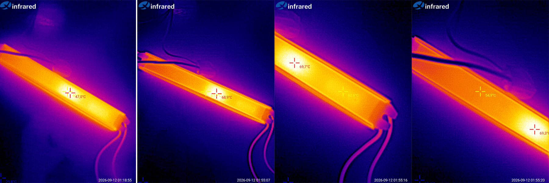
There wasn’t much to photograph. The first thermal image shows the overall view at 50% load; the next three are at 100%.
The highest recorded temperature was about 70°C, and judging by its location, that’s the transformer. The rectifier is clearly to the right, a little cooler at about 62°C.
In any case, I have no complaints about the heating, at least in its current form.
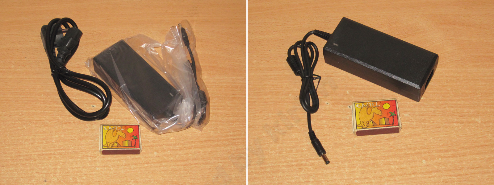
A desktop model rated at 72 W, 12 V, 6 A.
The stated input voltage range is 100–240 V.
The cable exits in the more familiar straight-through arrangement, and it comes with a standard “computer-style” power cord.
The layout is very similar to the 36 W desktop model shown earlier, but it’s clear that the transformer is larger and the input capacitor has a higher capacitance. Even at a glance, you can tell this power supply is more powerful.
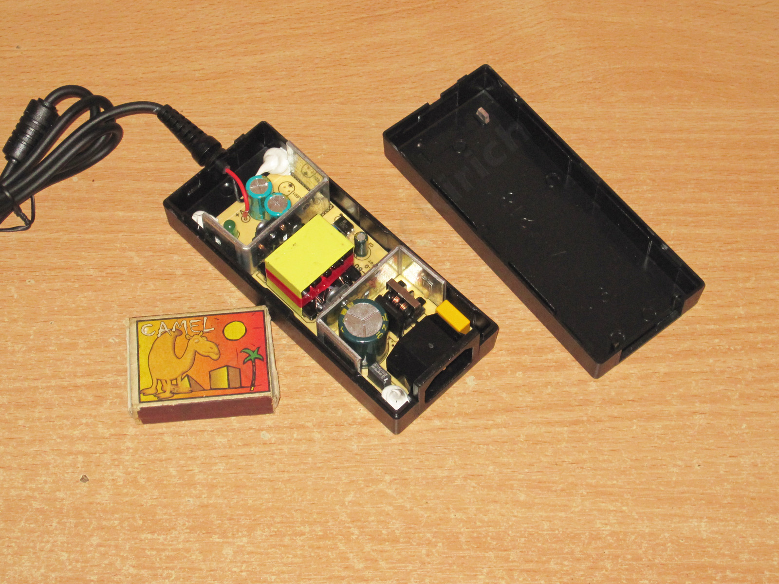
The board is secured inside the case with three blobs of sealant. If it holds, why not? I think that’s better than simply pressing the board against the transformer with a rubber pad.
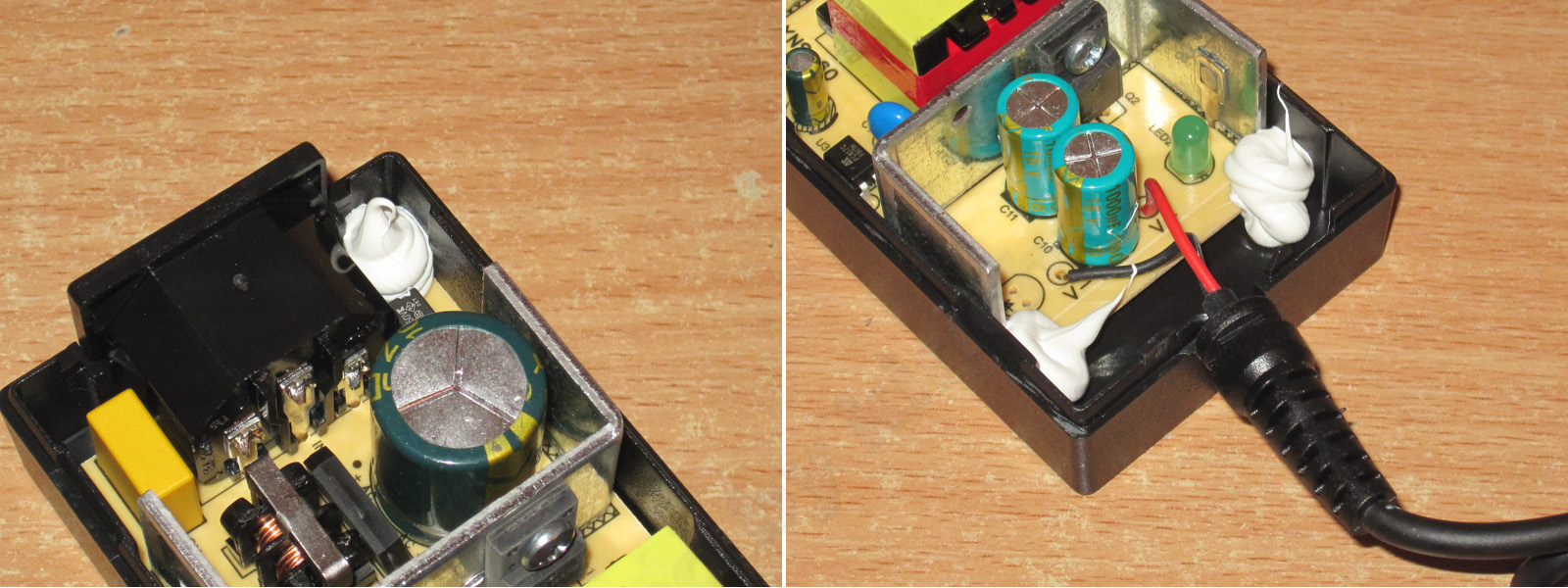
The layout is typical, with U-shaped heatsinks. I actually like this arrangement, although it works less well in a closed case than when the heatsinks run along the board.
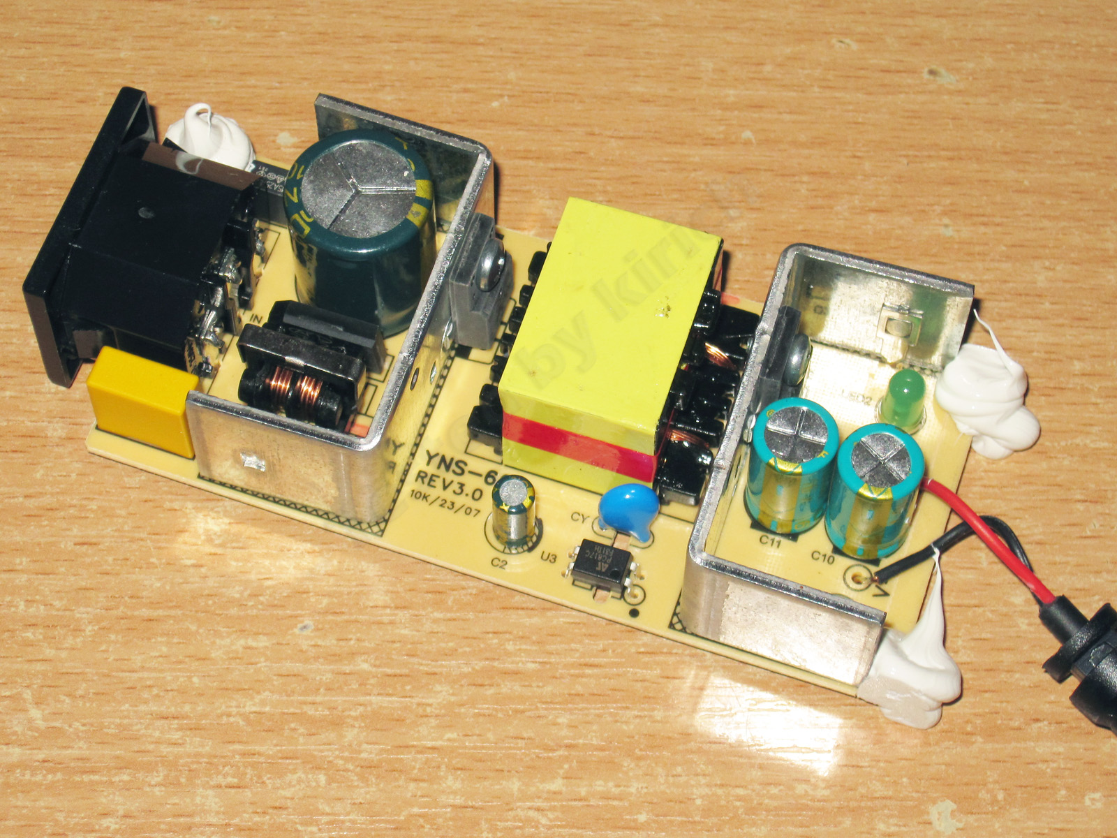
1. It has an input filter, but they skimped on the varistor—and on a few other things, too.
2. A 5 A, 650 V transistor, which is a typical choice for this power rating.
3. A 10 A, 100 V output diode assembly, which is a bit undersized for a 6 A power supply, though it should work.
4. A pair of 1000 µF, 16 V capacitors.
The board is very neatly laid out. I’ll note the proper topology of the output power stage.
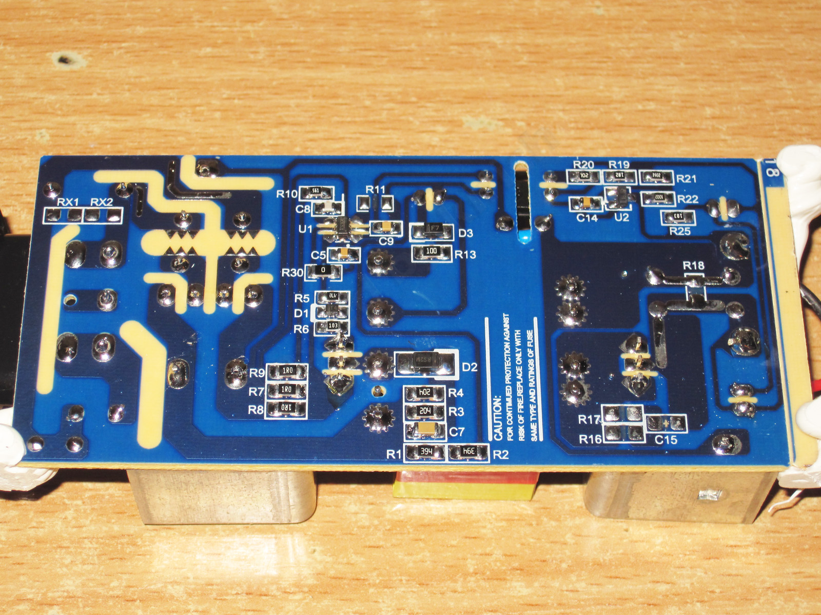
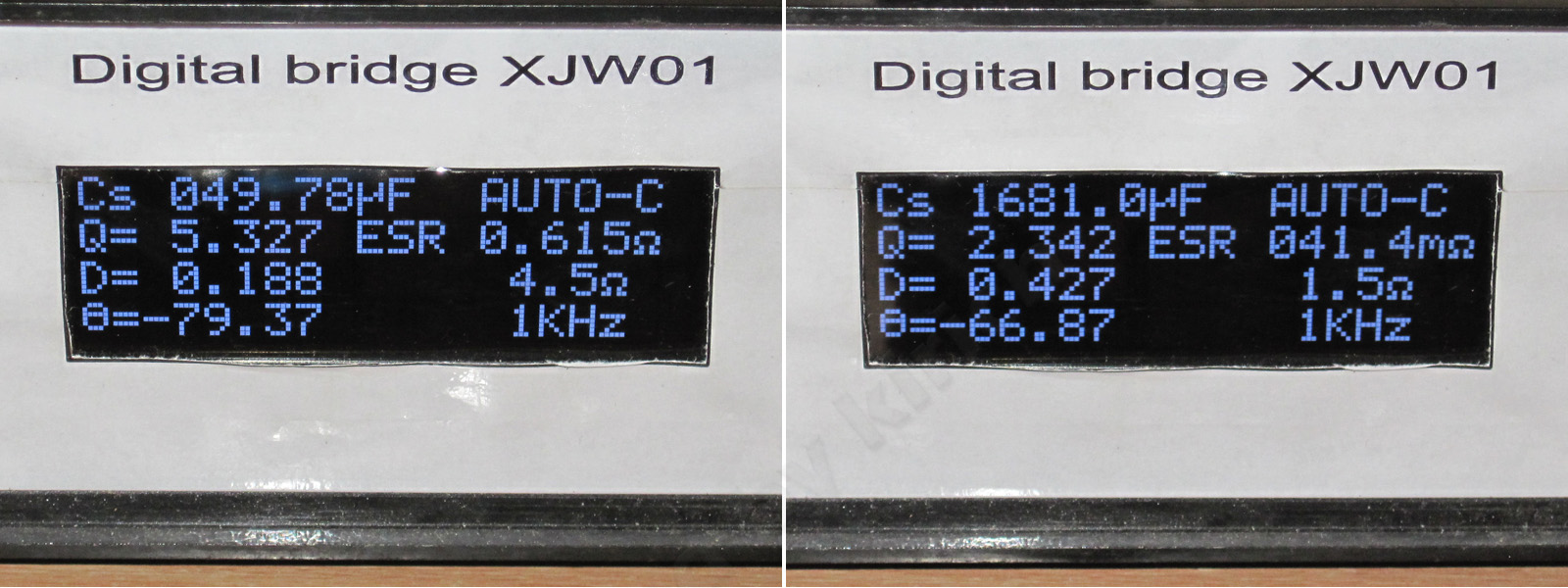
The input capacitor’s actual capacitance is 50 µF, which is on the low side. The output capacitors add up to about 1700 µF, which is also not much.
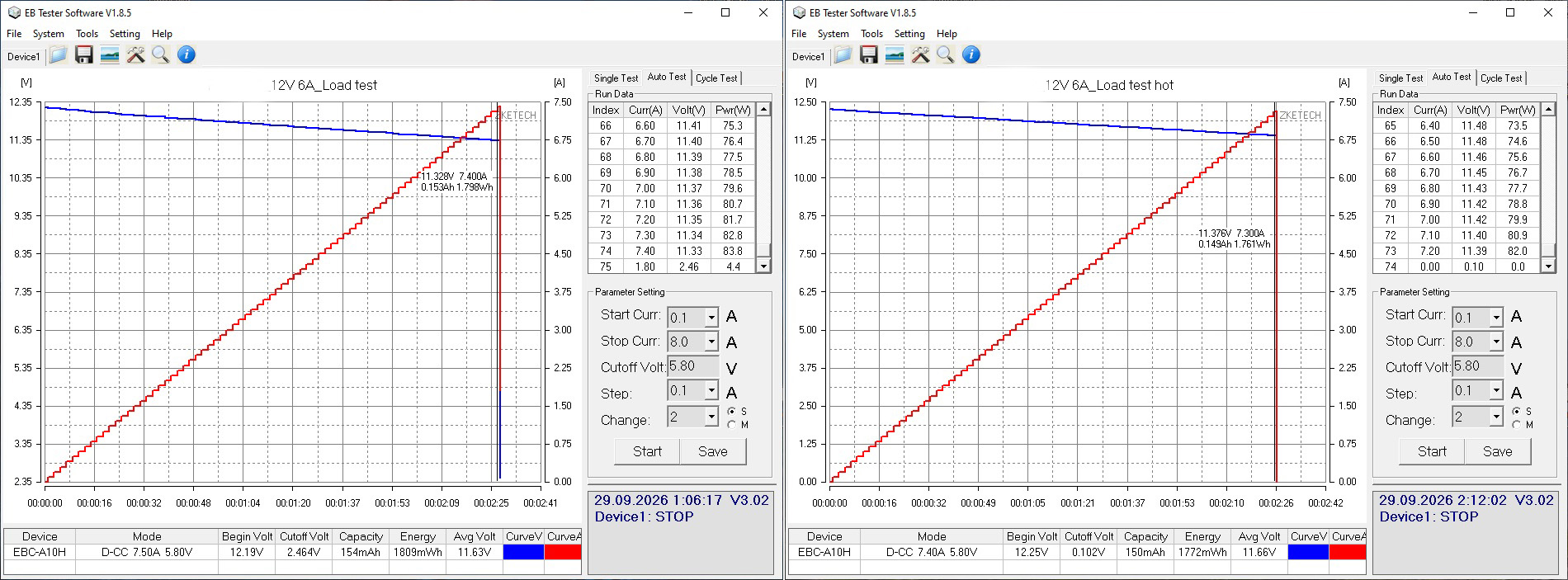
The protection is set to trip at around 7.3–7.4 A. That’s basically fine for a 6 A power supply, even if it’s at the upper limit, but in this case it’s best to look at the load test results.
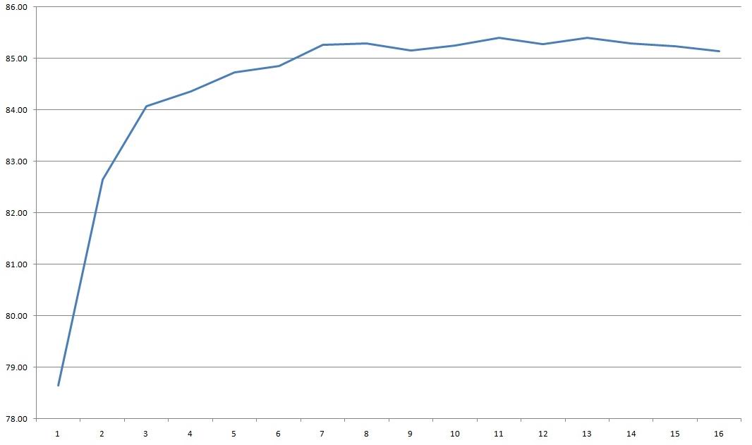
Efficiency was measured over a range of 0.4–6.4 A and came in at around 85–85.5%, which seems fine to me.
Ripple with no load and at currents of 2, 4, and 6 A.
Somewhat high: the main component is about 380 mV, rising to nearly 650 mV if you include the “spikes.”
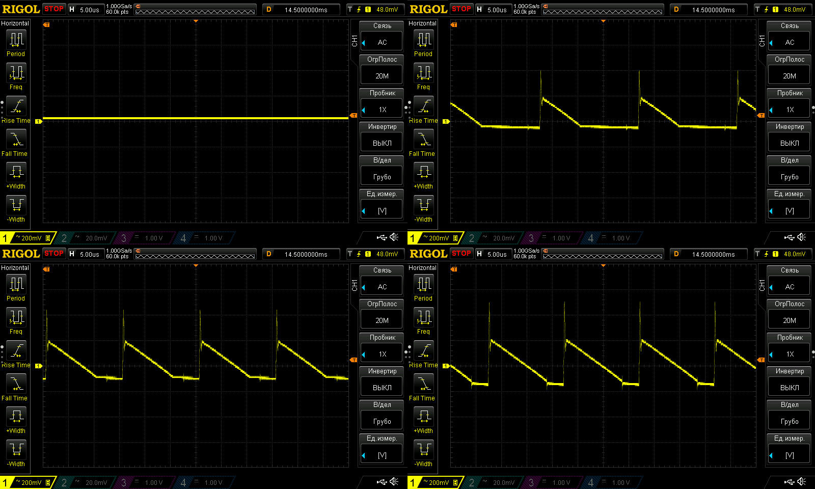
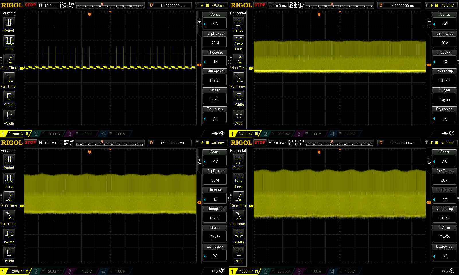
At low frequencies, it’s basically fine, aside from the large overall swing. There are no particular issues at 100 Hz.
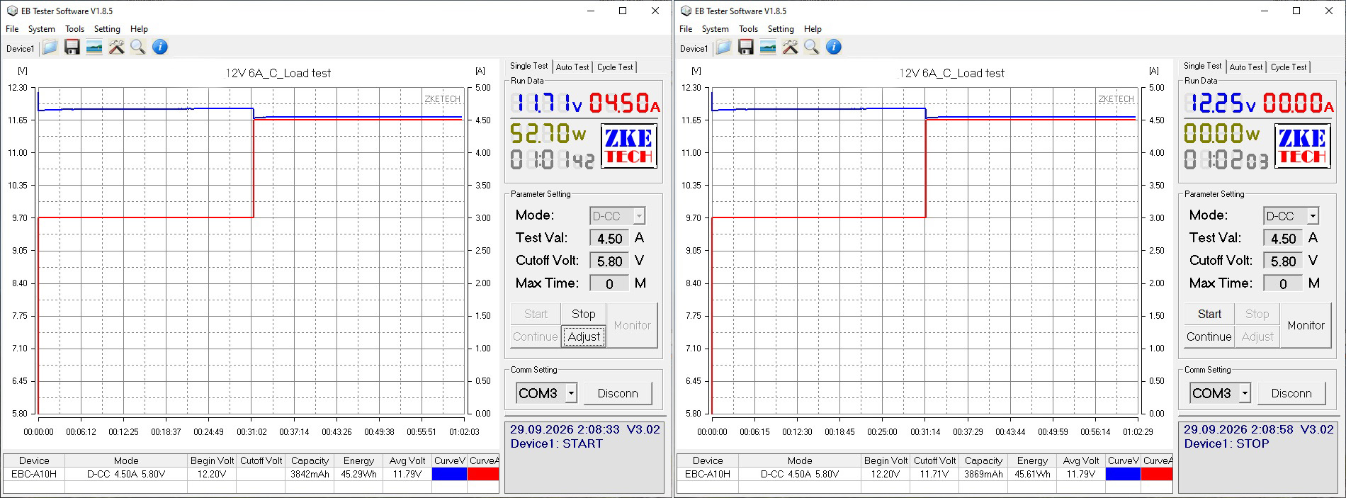
The load test was first run at 3 A, then, based on the temperature readings, at 4.5 A rather than the expected 6 A.
The voltage has a slight positive temperature coefficient, around 50 mV, which can safely be ignored.
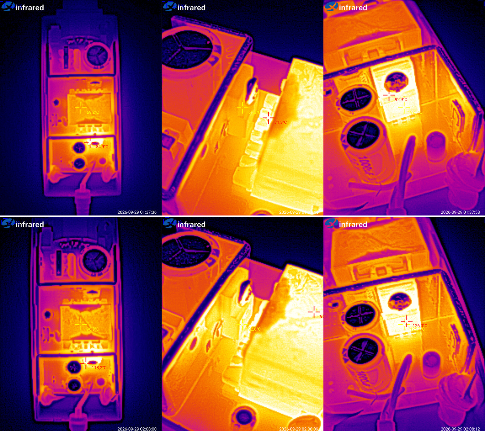
Temperatures:
3 A — transformer 69°C, transistor 61°C, diode assembly 93°C
4.5 A — transformer 96°C, transistor 93°C, diode assembly 126°C.
The temperature rise is why I ran the second part of the test at 4.5 A instead of 6 A: 4.5 A is the maximum continuous current at room temperature.
In other words, allowing for higher ambient temperatures, the actual continuous current is no more than 3.5–4 A. Replacing the overheating diode assembly won’t change much, since increasing the load would just make the transformer overheat next.
100 W model, 12 V, 8.3 A.
The stated input voltage range is “narrow at the top”: 180–240 V.
This is the umpteenth time I’ve seen the upper limit listed as 240 V. I wonder if the manufacturer knows that our mains voltage is now allowed to reach 253 V? Even before, it was 220 ±10%, i.e. up to 242 V.
I’d be concerned to see it rated for only up to 240 V.
I don’t know why, but I like the look of this design, even though there’s nothing particularly convenient about it.
Judging by the markings on the packaging, there are also 24, 36, and 48 V models.
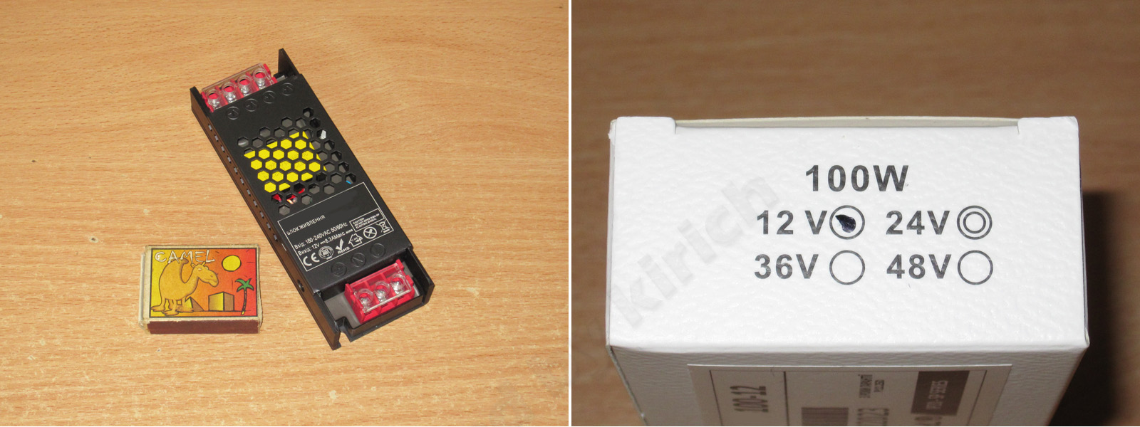
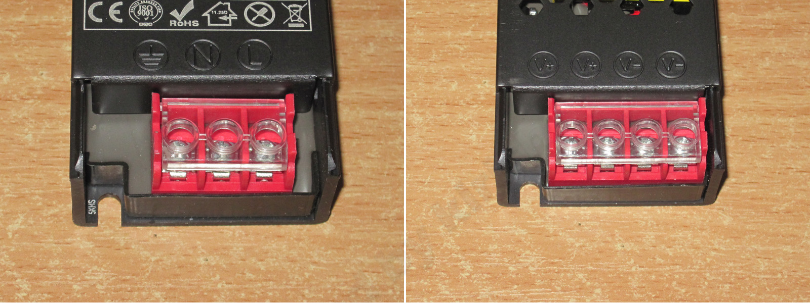
It connects via screw terminals and has a protective cover. There are four output terminals, two for each pole, which can be handy sometimes.
I forgot to take a photo, but there’s an issue with the cover. It was extremely difficult to remove. The reason is that it’s made of aluminum—or, judging by how it cracks at the bend, duralumin. Who thought it was a good idea to make a cover out of such thick, unsuitable material...
There are small fins on the bottom of the case (though “fins” is a bit of a stretch), which are more decorative than practical.
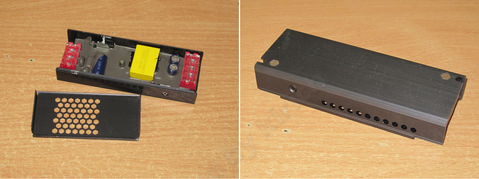
This power supply has a moisture-resistant design (not to be confused with waterproof). The components are pressed against the case through thermal paste. Overall, it’s a classic-looking, neatly made unit.
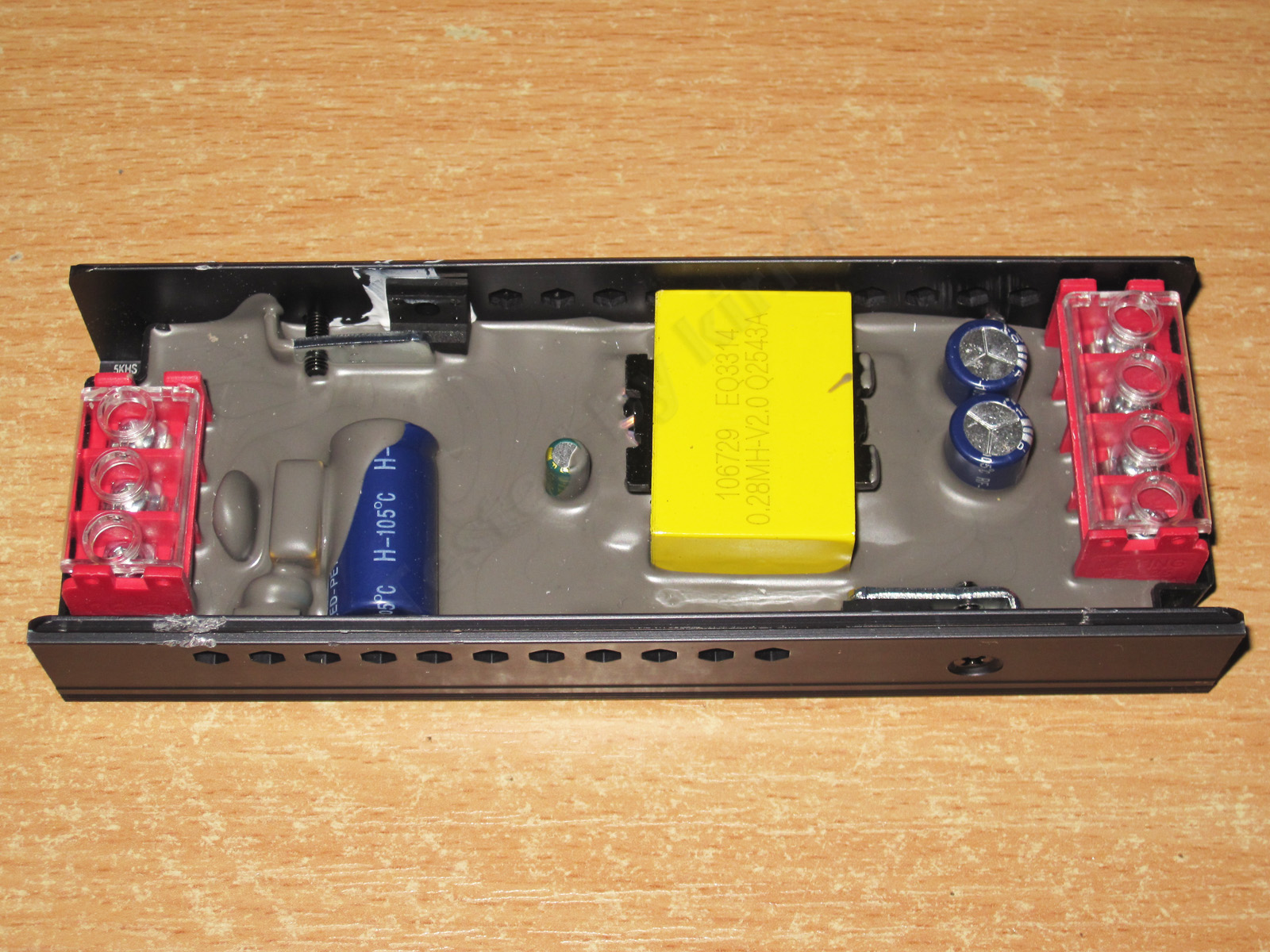
The input capacitor’s capacitance isn’t visible, and I didn’t feel like digging it out. The output capacitance is 1000 µF.
It also has a full input filter, including both a thermistor and a varistor, which are clearly visible under the potting compound.
The input capacitor’s actual capacitance is just 43 µF, far too low for a 100 W model. The output capacitance of 1900 µF is also on the low side, and the ESR is rather high.
The protection is set very close to the maximum current, at around 8.4–8.5 A. I should note a very curious relationship between the output voltage and the load at the beginning of the range. I wonder why...
Efficiency was measured from 0.5 to 8.5 A in 0.5 A increments and came to around 86%.
Overall, not a bad result, but once again we have an unusual graph, with a bump at around 50% load.
Ripple with no load and at currents of 2.5, 5, and 7.5 A.
This is a rather disappointing picture: 500–600 mV over most of the waveform and 1 V peak-to-peak. And what’s even worse, I’m almost certain the capacitors won’t last long under these conditions.
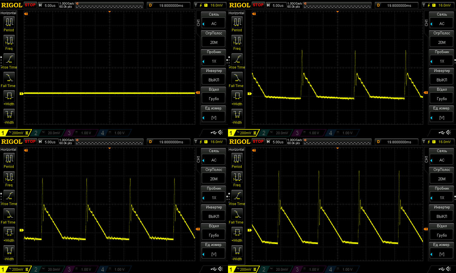
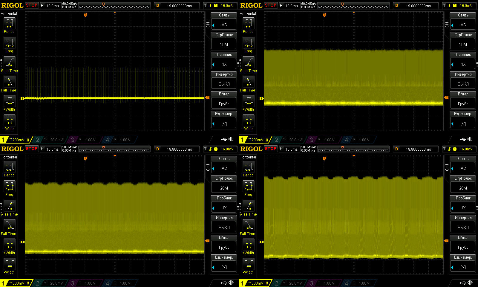
Against the overall background, the 100 Hz ripple is almost unnoticeable, of course, but this much ripple in the “overall background” isn’t good.
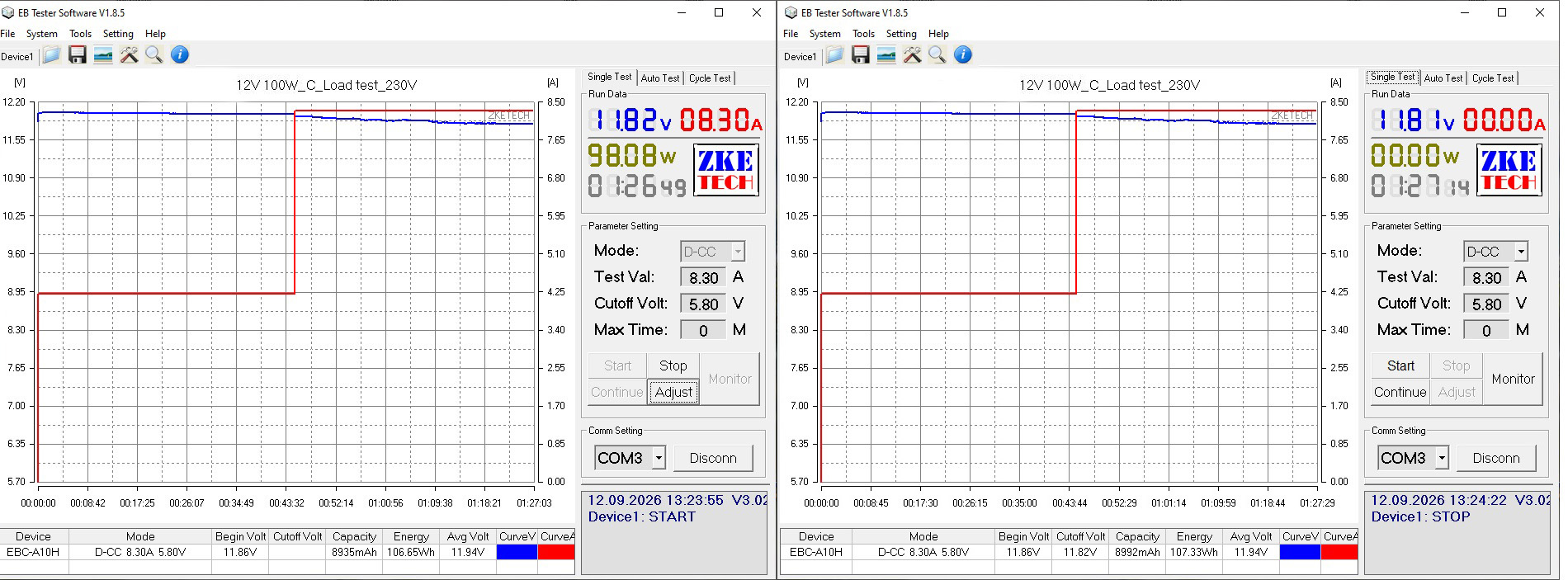
The load test was performed at currents of 4.2 and 8.3 A.
There’s essentially no relationship between voltage and warm-up, but if you look at the voltage graph at 8.3 A, you can see that the voltage drops. Look more closely, and you’ll notice that it first jumped up, then started dropping after the current was increased to 8.3 A.
In other words, the output voltage increases with load current, and the subsequent drop is caused by the power supply entering the mode just before protection trips.
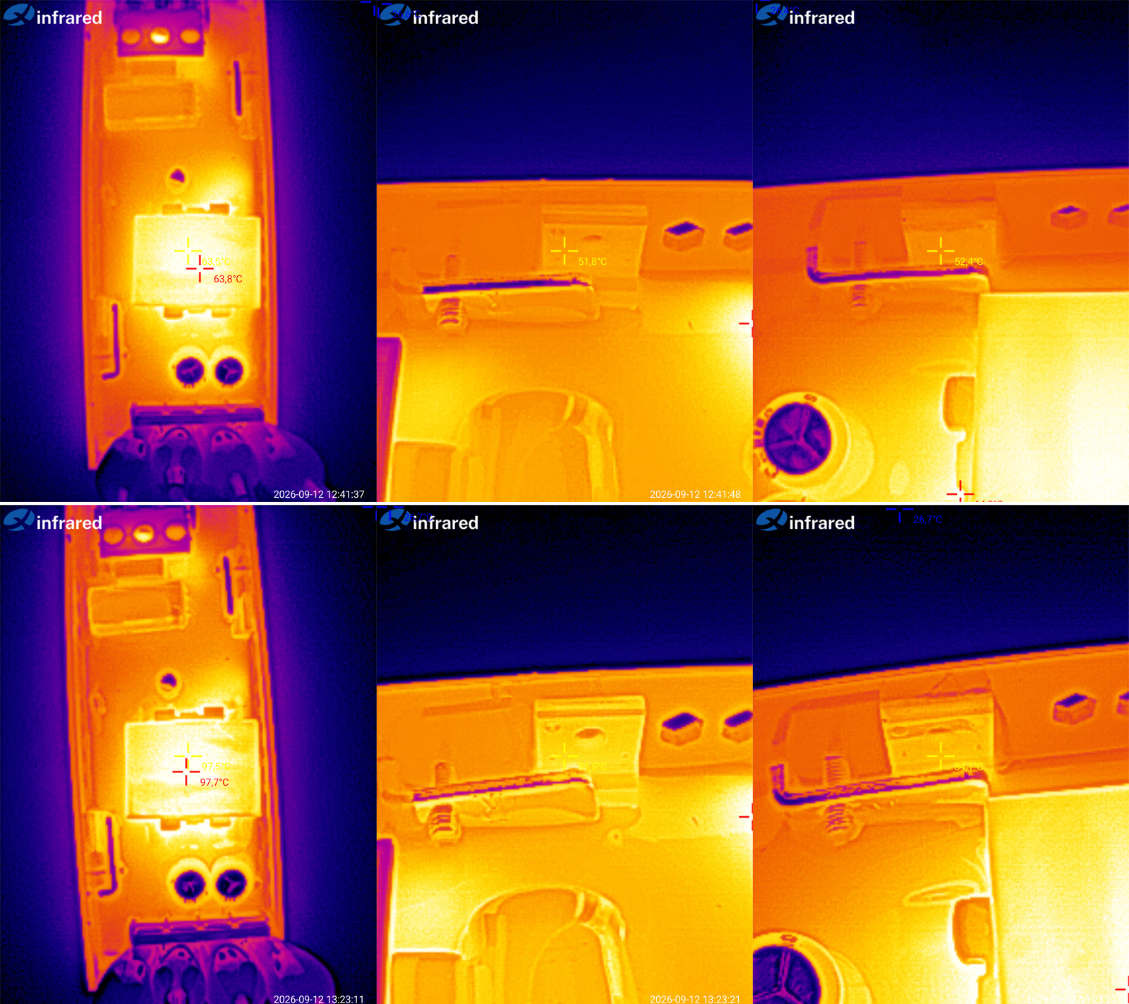
Component temperatures:
4.2 A — transformer 64°C, transistor 52°C, and diode assembly also 52°C
8.3 A — transformer 98°C, transistor 81°C, diode assembly 84°C.
That seems a bit high to me. There’s almost no headroom for a rise in ambient temperature, and considering that power supplies like these are sometimes installed in electrical panels, above suspended ceilings, and even in outdoor enclosures, I think the maximum current here is closer to 6.5–7 A.
Another 100 W model, rated at 12 V and 8.3 A, but this time in a sealed enclosure.
The specified input voltage range is 180–264 V, which is more appropriate for our mains supply.
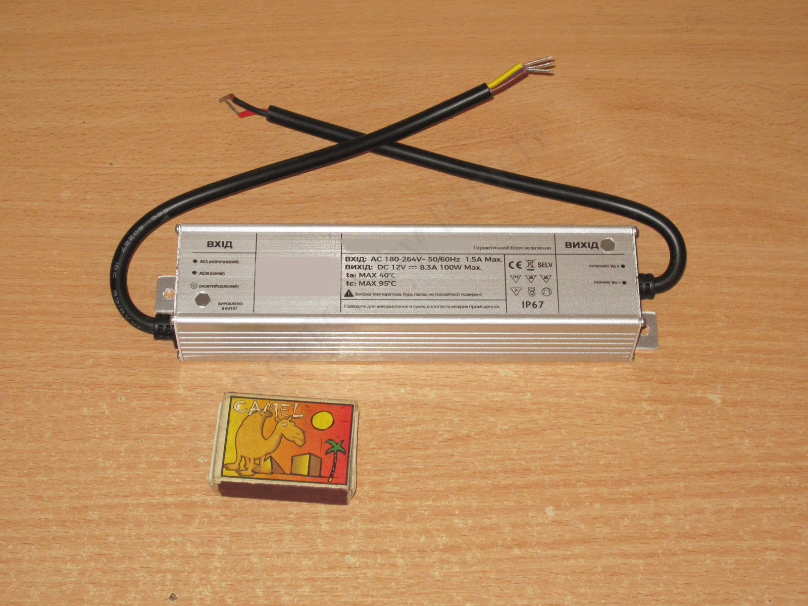
There’s not much to show here: end caps secured with self-tapping screws, wires with a sufficient cross-section—in short, nothing special.
Protection is set to around 9.4–9.5 A, with no issues. There’s a slight voltage drop under load, which is perfectly normal since the measurements are taken after the output cable.
Efficiency was measured from 0.5 to 9 A in 0.5 A increments and came to around 85.5–86%. If it weren’t for the fairly typical efficiency—though it’s normal for this power level—I’d have guessed from the shape of the graph that it uses a synchronous rectifier.
Ripple was measured with no load and at currents of 3, 6, and 9 A.
Surprisingly, the results here are noticeably better than with the previous power supply: around 130 mV over most of the waveform, with a peak-to-peak value of 220–230 mV.
I wouldn’t call the ripple low, exactly, but I can’t call it excessive either. It’s quite acceptable given the voltage and load current.
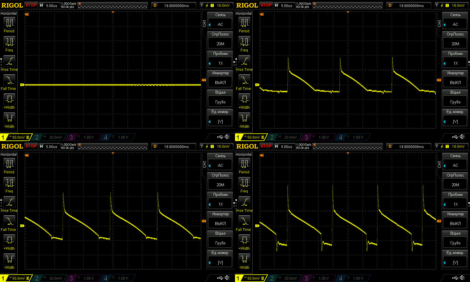
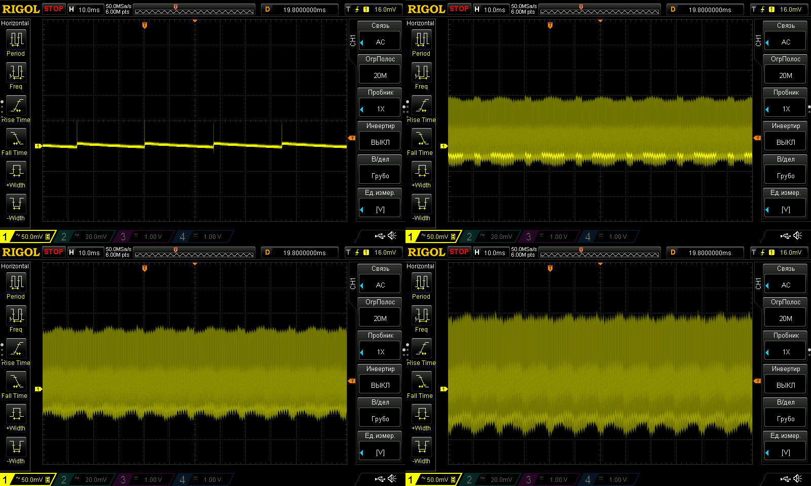
Even at 100 Hz, I wouldn’t say there’s anything bad going on. Yes, there’s a bit of ripple, but again, it’s not critical.
I have a strong feeling that this and the previous unit are two completely different power supplies, with their own circuit design quirks and made at different factories.
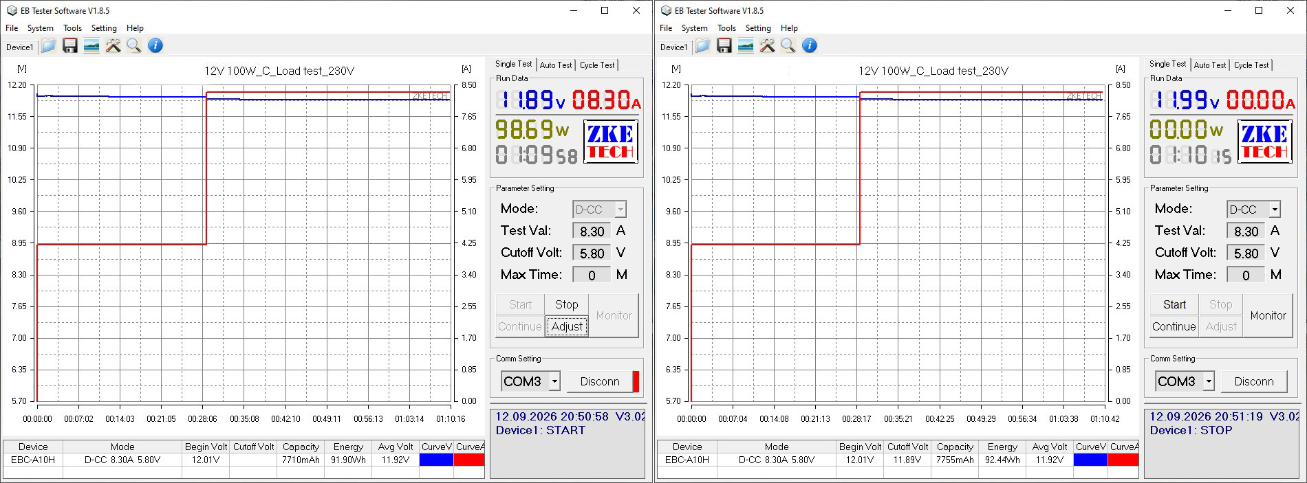
The load test was performed at currents of 4.2 and 8.3 A. I wanted to try 10 A, but changed my mind—I don’t want anyone accusing me of torturing the test subjects :)
There’s a slight negative relationship between voltage and temperature, but it’s only 20 mV.
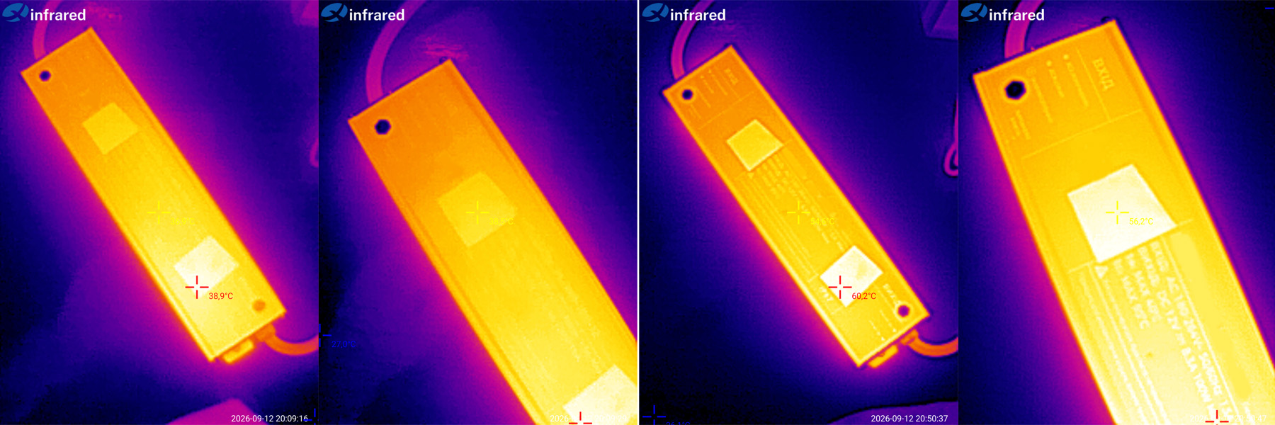
For the temperature test, two small pieces of electrical tape were stuck to the power supply’s case to ensure accurate temperature measurements.
At 4.2 A, the case warmed up to 39°C; at 8.3 A, it reached 60°C. In both cases, the hottest area was near the output end of the power supply.
It’s hard to say much here. Yes, it gets hot, and yes, it’ll burn your hand, but yes, that’s normal too.
The most powerful power supply in the test is a desktop model rated at 120 W, or 12 V and 10 A.
The specified input voltage range is 100–240 V.
The package includes the power supply and a mains cable.
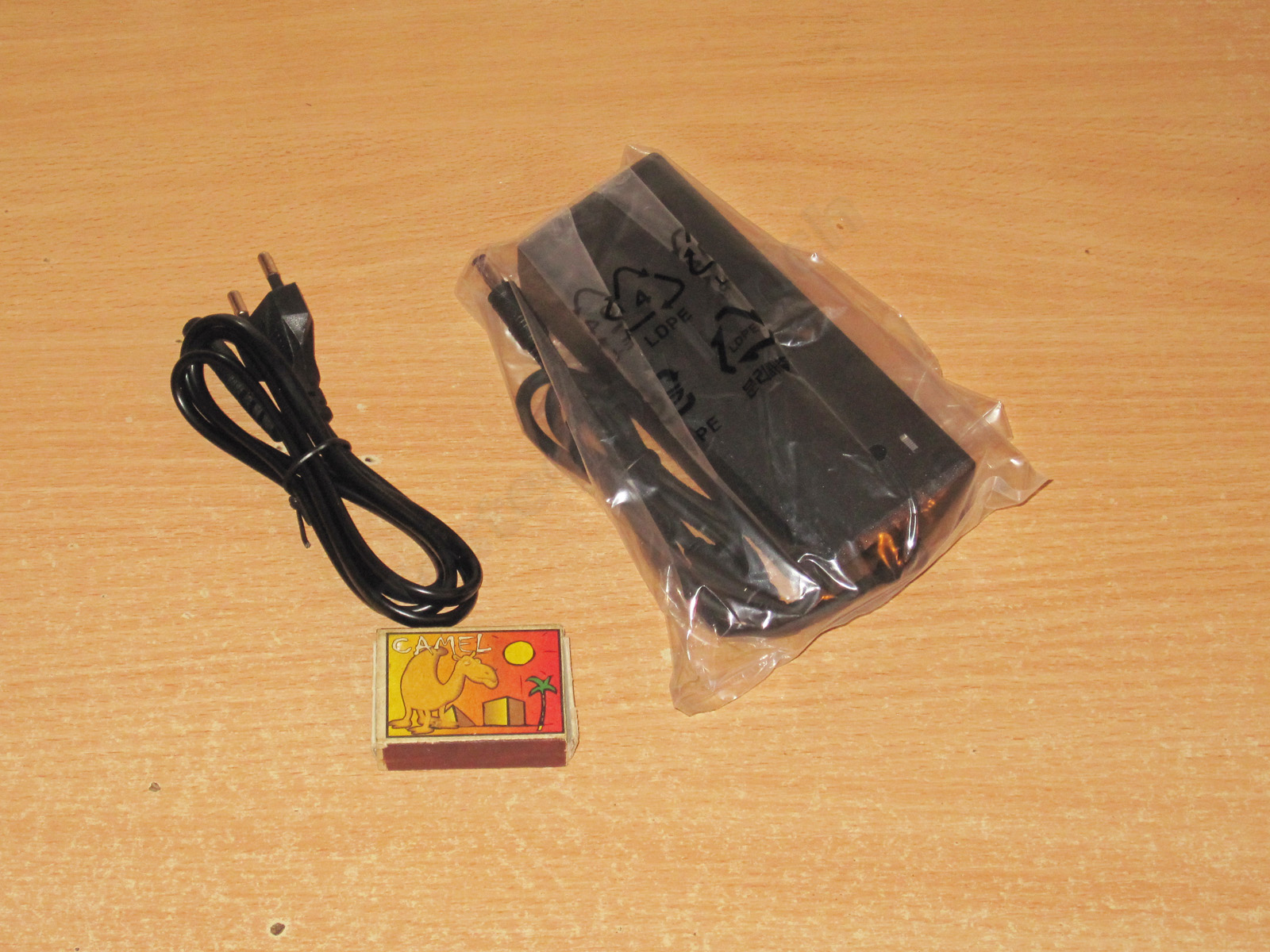
The case is relatively compact, especially for the claimed power output. That means either it uses a proper, expensive design—or the second option.
But what surprised me more was the cable. The connector is the usual figure-eight type; I honestly don't understand why they didn't use the standard "computer" connector.
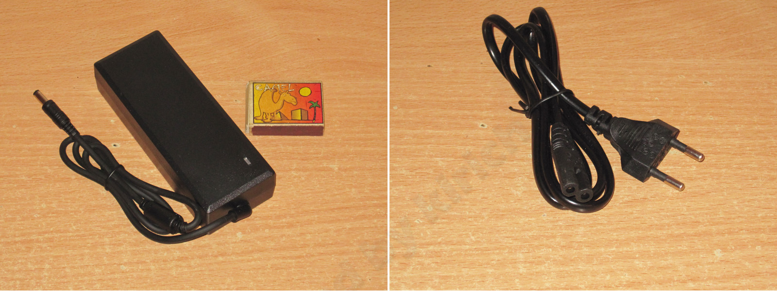
I opened it up. Nothing unusual, just another power supply. The transformer is rather small for 120 W, though.
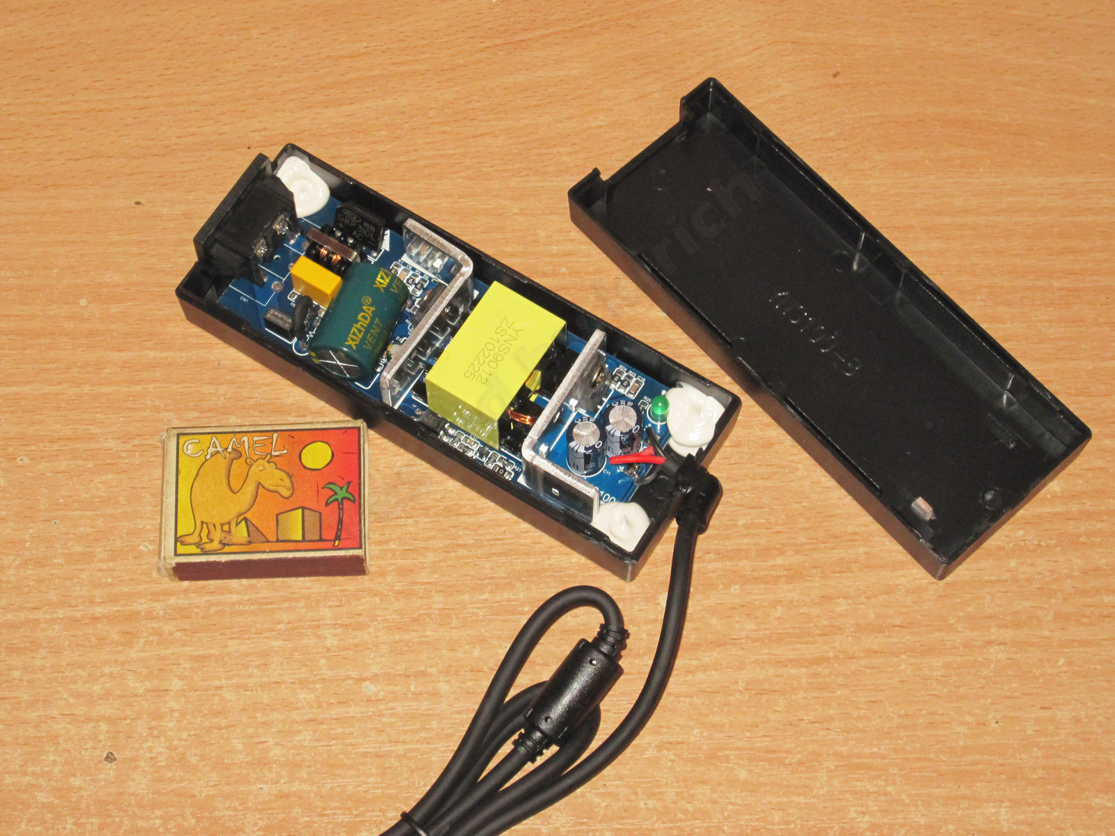
The board is neatly laid out, but I was even more surprised that they used this kind of mains connector after all. Both the case and the board could easily accommodate a standard—or, more precisely, more common—"computer" connector...
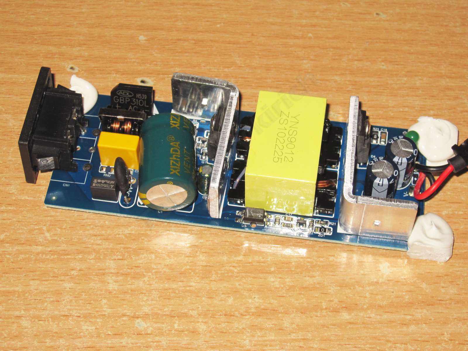
1. There is an input filter. No varistor, but that's not really critical; what's more important is that they didn't forget the thermistor.
2. The input capacitor is rated at 82 µF, which is already rather small for 120 W, even on a 230 V mains supply. I won't even get into operation at 100 V.
3. The high-voltage transistor is rated for 10 A and 650 V. That's basically fine here.
4. All the feedback circuit components are placed at the edge of the board, and you can see a protective slot under the optocoupler.
1. There is a Y capacitor, and judging by its appearance, I can say that all the power supplies in plastic cases shown in this article were made at the same factory.
2. The secondary winding consists of just a few relatively thick strands.
3. The output rectifier is a 30 A, 100 V diode assembly. Basically fine, as long as you don't let it overheat.
4. And just two 1000 µF capacitors for 10 A?
As with the previous similar power supplies, I have no complaints about the circuit board. It's a little dirty, but that happens—maybe the assembler was just taking lunch :)
The input capacitor's actual capacitance is 69 µF, which was to be expected. The output capacitance is 1750 µF, but the capacitors are a little better than those in the 72 W version.
The overcurrent protection trips above the 10 A threshold, both when cold and when hot. A follow-up test showed that it trips at 10.6 A.
At 10 A, the output voltage drops by 0.65 V; essentially, the entire drop is across the output cable.
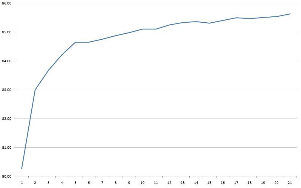
Efficiency was measured from 0.5 to 10.5 A in 0.5 A increments and came out at around 85–85.5%.
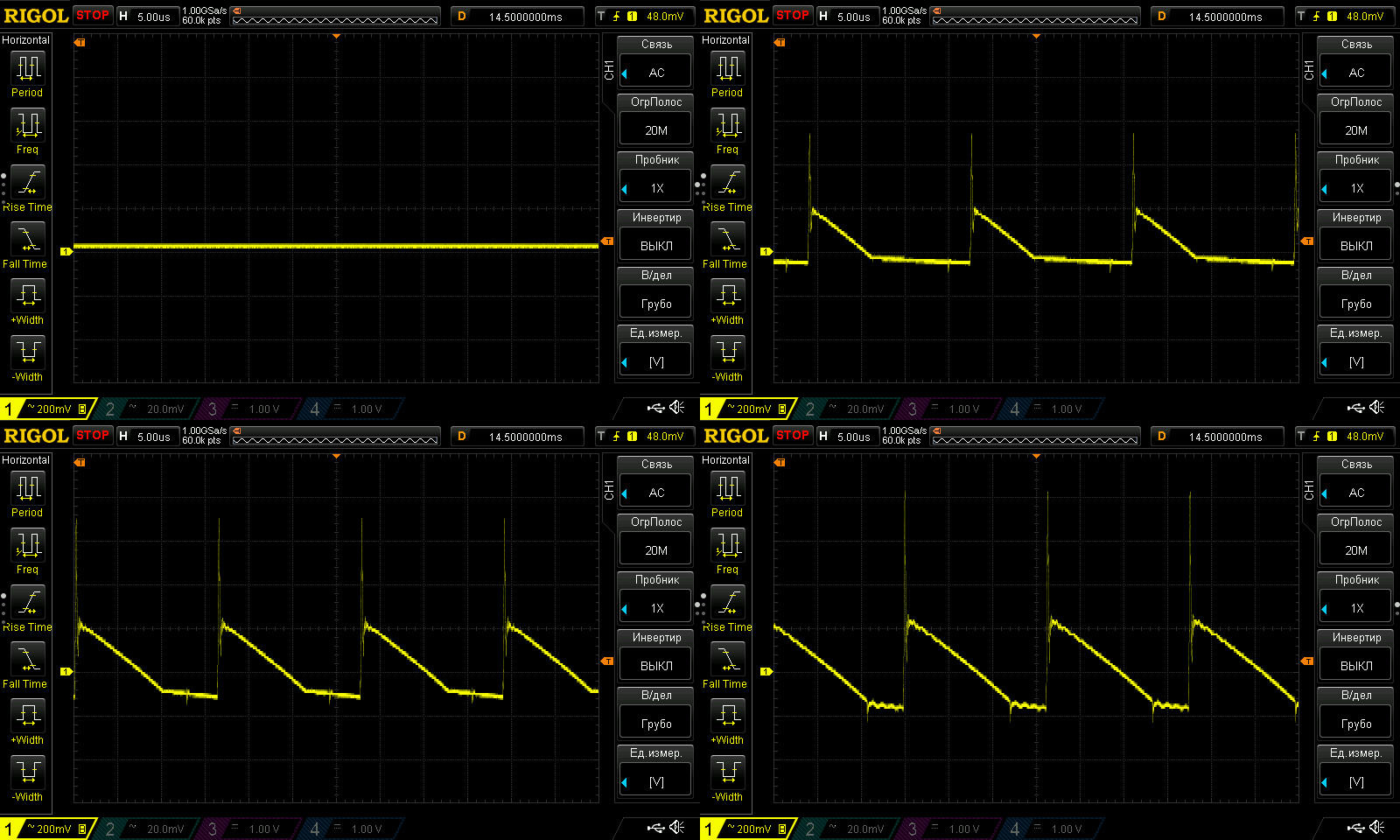
Ripple with no load and at 3, 6.5, and 10 A.
At maximum current, I measured about 400 mV of main ripple and 1 V including the "spikes". So, mediocre again—and I wouldn't say things are noticeably better at 6.5 A. The ripple is within acceptable limits, of course, but the question is whether it will start increasing over time, since the output capacitors are operating under fairly demanding conditions.
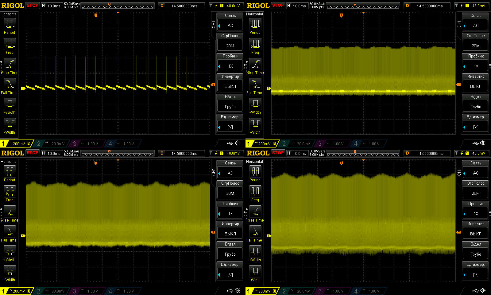
At low frequency, you can see a little 100 Hz ripple, especially at full power. The input capacitor is a bit undersized, but against the overall background, I wouldn't say the ripple is all that large.
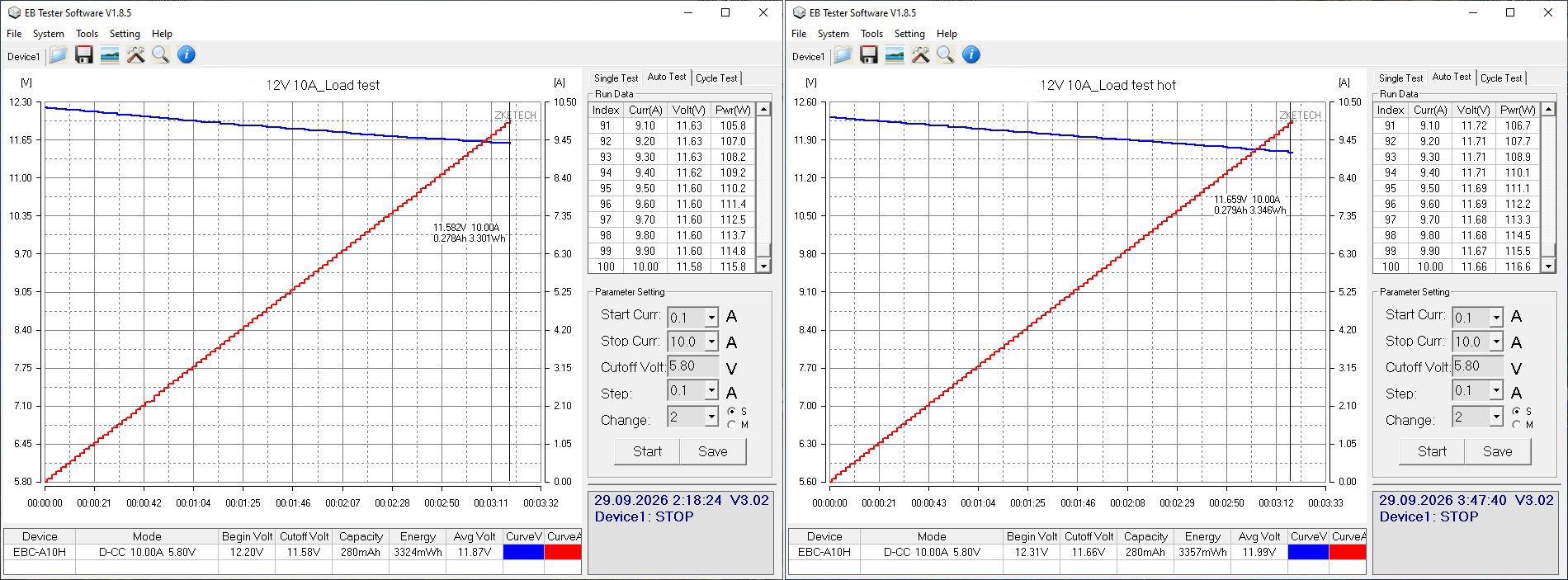
The load test was run in two modes: first at 5 A, or 50% load, and then at 6 A. I think you've already guessed why there's no test at 10 A.
The output voltage has a positive temperature coefficient of about 70 mV, which isn't critical.
And of course, here's the thermal image.
5 A — transformer at 90 degrees, transistor at 87, and diode assembly at 120.
6 A — transformer at 110 degrees, transistor at 108. The diode assembly went beyond the thermal camera's maximum range, so we're seeing 135 degrees.
There's not much to comment on here. It's clear that at 5 A the power supply is already struggling, while at 6 A it overheats—and that's at room temperature. There's obviously no thermal protection, so I see two possible outcomes if you run it at full current. First, the transformer starts to saturate and the overcurrent protection trips, at least for a while. The second possibility is less optimistic.
Conclusions.
1. 36 W, 3 A adapter. The actual maximum power is 30 W; above that, the protection trips. The actual continuous power is closer to 20–25 W. It's a fairly basic unit, apparently inexpensive. Ripple is mediocre, but it should work, especially since it uses a dedicated chip and most likely has thermal protection.
2. 36 W, 3 A desktop power supply. This one looks clearly better than the previous one. Ripple is slightly higher, and its thermal performance and power output are adequate at room temperature. However, the protection current is set about twice as high as it should be, which could have serious consequences since there is no thermal protection.
3. Sealed, 36 W, 3 A. The protection current is set correctly, and there are no issues with heating either, but output ripple is quite high, around 500 mV, and the low-frequency waveform isn't very pretty either.
4. Desktop, 72 W, 6 A. The construction is decent and neat. The protection current is 7.4 A, which would be fine if the actual maximum continuous current weren't only about 4.5 A. Ripple is around 400 mV, so the only real complaint here is that the rated power is overstated by a factor of one and a half.
5. Weatherproof, in an enclosure, 100 W, 8.3 A. I really like the build: neat, attractive, and pleasant to hold. The protection is set right on the limit, but that's actually a good thing for this unit, since it would simply overheat under a heavier load. There is one caveat regarding heat, related to the typical use case: power supplies like this often have to operate over a wider temperature range, so I wouldn't load it beyond 75–80 W. And the ripple at maximum current is around 600 mV—too much.
6. Sealed, 100 W, 8.3 A. No complaints about the build, the protection current is set correctly, and, surprisingly, ripple is within spec. Heating is also within normal limits. There's not much to criticize, really; it's a reasonably decent 100 W power supply.
7. Desktop, 120 W, 10 A. I might even have praised this one: it's neatly assembled, the protection is set to 10.6 A against a rated 10 A, and ripple is generally within the normal range for a budget unit. But the fact that its actual power is only about 60 W, despite being rated at 120 W, wipes out all its positive points.
The conclusions give a brief summary; for the details, it's best to refer to the full review.
I'd also point out what almost all the power supplies shown here have in common: ripple is mostly average or noticeably above average, and the power rating is often overstated, leading to overheating. At the same time, the assembly is fairly neat and the circuit board is well thought out, although the components are often budget-grade and the capacitors are frequently undersized.
It's worth noting, though, that if you're powering something like LED strips, ripple isn't critical. But power supplies are versatile devices, and they're often bought for more than just that. LED lighting does, however, bring its own issues to light.
The ripple situation was interesting, actually. I finished checking everything, then went through the materials and realized that the ripple was noticeably high rather often. But I'd tested other power supplies just shortly before that, and everything had been fine. My first thought was that maybe I'd accidentally tested the earlier ones with the 1:10 probe attenuation enabled. I didn't want to take any chances, so I grabbed one of the earlier units at random, hooked up the oscilloscope, confirmed everything was fine, and relaxed.
This model is included in the summary table: Comparison of power supplies: ripple, efficiency, and temperature rise
The figures from this review are in the measurement database: Power supplies
Calculate manuallyAll calculators
Discounted products
You may be interested in



Discounted products
Support the project
All the content on the site and the advice are free, but we’d be grateful for your support of the project and the channel!
Comments1
Discuss on the forumThere’s already a forum thread, but no replies yet. Be the first!
Post on the forumOnly registered readers can comment. It takes a minute to sign up, and you can log in with the same account you use on the forum.
Log inRegister
Comments are published in their original language.