
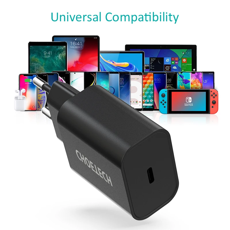
CHOETECH Q4004 power supply (charger) with 60 W PD support
$14.51
As usual, I’ll inspect it, run some tests, take it apart, and share my conclusions.
The store page also has a cheaper option than the one listed in the title, but it doesn’t include an adapter for European outlets. There’s also a more expensive option that comes with a cable.
Why was I interested in this particular power supply, and why did I order it? It’s simple: it would be handy for charging my smartphone and powering my TS100 soldering iron. Of course, 24 V would be more useful for the latter, but there aren’t any QC/PD power supplies like that, and a regular power supply is less versatile and the same size.
It comes in a cardboard box, with the unit held in a tray inside. That earns it a small bonus point: there’s less chance of damage during shipping.

Besides the charger, the package includes a manual and a small slip of paper that actually came in handy—but more on that at the very end of the review.

Both the box and the manual list the specifications, but don’t separate them by QC and PD, which could be a little confusing.

The case is made of matte plastic, which earns the manufacturer another small bonus point. Fingerprints are visible, but only faintly.
The power supply itself also lists its specifications, but it’s still hard to tell what it can do in QC mode.
The European plug is an adapter that fits over the flat prongs. The manufacturer presents this as a more convenient solution for travel. I won’t argue: it’s a decent option and reasonably reliable.
When plugged into an outlet, the power supply doesn’t block access to adjacent outlets or switches.
There’s one output connector: Type-C.

Above are the dimensions compared with a matchbox; the store page has the full measurements.

Now for the tests.
Checking support for different protocols.
1, 2. My main tester showed support for everything except QC 20 V, but my second tester disagreed and marked half the list in red.
3. Power Delivery: version 2.0 is supported, with a maximum of 20 V at 3 A.
4, 5. QC 3.0: the range here is 4–12 V. If I try to set the voltage any lower, it drops in 0.2 V steps, but immediately jumps back up. I’ve seen other controllers allow adjustment from 3.6–3.8 V.
6. Samsung AFC 9 V: sets without any problems.
7, 8. Huawei SCP: adjustable from 4.00 to 5.53 V. That’s not a very wide range; I’ve seen controllers that adjust from 2.98 V.
9. Huawei FCP 9 V is supported, though in reality the output is 8.91 V, not 9 V.

Everything looks good, except for one thing. The store page claimed support for PD 3.0, but as I showed above, I only saw version 2.0. I wouldn’t call this a major issue, but version 3.0 is more flexible: instead of being limited to fixed voltages of 6/9/12/15/20 V, it lets you adjust the voltage in 20 mV steps.
By the way, the wall outlet looks a little odd. In case you didn’t notice, the picture suggests it’s installed vertically :) Of course, you can install one that way, but it’s very rare, so your power supply will usually be plugged in as shown in the photo above—that is, horizontally.

Load tests.
I don’t have a suitable adapter for connecting a load, so I had to solder wires directly to the USB tester. It’s crude, but there was no other way—especially since I needed to connect upstream of the current-sense resistor.

First, the basic voltage used by most devices: 5 V.
With no load, it’s 5.14 V. As the load increases, the voltage rises to 5.32 V at the rated current of 3 A. The maximum was 3.5 A, after which the protection kicked in.
On the one hand, it’s all pretty good: the power supply compensates for voltage drop in the cable. On the other hand, the voltage exceeded the standard 5% tolerance by 70 mV. I wouldn’t call that a major issue, especially since that 70 mV will easily be lost to the cable’s resistance, but it is what it is.

To keep the review from getting too long, all the remaining tests are hidden under the spoiler.


Ripple was checked in four operating modes: with no load and at the maximum current of 3.3 A for each of three voltages: 5, 12, and 20 V.
1. With no load, the PWM controller switches to "green mode," meaning the frequency of the control pulses is reduced. Unfortunately, this produces a faint but distinctive buzzing sound, which disappears completely when the load exceeds 6–7 W.
2, 3, 4. Ripple amplitude is about 200 mV and is almost independent of the load. That's a bit high at 5 V, but fine in the other modes.
There are short spikes, but they aren't critical in this case, since they'll be smoothed out by the RC filter formed by the cable and the load.

Temperature.
I ran a 40-minute test with a 60 W load. The case temperature after 20 and 40 minutes is shown below. Since the case is plastic, it doesn't feel particularly hot, although 68 degrees is quite a lot. Also, the heat is concentrated in one spot.

Teardown
Of course, I had to take a look inside. There were some difficulties during disassembly, though they turned out to be a blessing in disguise.
The thing is, I first opened one cover, saw the circuit board, and decided I should have opened the other one. After removing the second cover, I found that it was just plastic—the main part of the case. So I had to remove the cover I'd started with first, too.
In the end, I completely disassembled the charger.

There's a small square of thermally conductive rubber on the transformer, transferring heat to the plastic main part of the case. That's very odd, since there's an air gap between the side cover and this part—in other words, a thermal insulator. In my opinion, the manufacturer could easily have made the inner part out of metal without compromising electrical safety, while improving cooling through better heat distribution.
It looks neat on the outside. Almost the entire board is coated with some kind of sealant, which helps distribute heat more evenly and reduce hot spots.

1. There's a proper input filter, along with a correctly rated fuse, but no protective varistor.
2. There's a thermistor, a decent bridge rectifier, and a Y capacitor. The output has three capacitors with a combined capacitance of about 2000 µF, which is also fine.
3. There are two 47 µF input capacitors.
4. The capacitance marked on the input capacitors seemed odd to me. At this size, branded capacitors are usually rated for no more than 22 µF, or perhaps 33 µF, but these are marked 47 µF. I measured 83 µF total, or 41.5 µF each. I measured them in circuit, though, so the actual value may be a little higher. That's plenty for 60 W at a 230 V input, but not enough at 115 V; I'd say it's right on the limit.

The charger is controlled by a WT6615F controller, with the synchronous rectifier transistor next to it.

I found a description of this controller online, and it turns out that it really does support Power Delivery 3.0. It's odd that the USB tester identified it as 2.0.
In addition to CV mode (voltage regulation), this controller also supports CC mode (current regulation), so it can be used to build proper battery chargers.
It also provides protection against overvoltage, undervoltage, overcurrent, and overheating.

However, implementing the protection functions listed above requires a transistor to disconnect the output from the load, and I couldn't find one here. I didn't see a temperature sensor either, though both components could be tiny and simply hidden under the sealant.

I also found details of a 90 W charger using the same controller. This leads me to conclude that the controller itself is interesting, but here it's being used in a heavily stripped-down mode.

The board color and marking style are very similar to those of the lower-power model I also took apart. It looks rather basic, but quite neat: the board is clean, and the leads are trimmed evenly before soldering, not afterward.

1, 2. Primary side. The controller is marked 362J52. I took a quick look to see what it was, but couldn't find a datasheet.
3. Synchronous rectifier controller LN5S03.
4. To inspect the transistor, I had to desolder it. I figured it might come in handy if the unit ever needs repairing.

I’ve mentioned before that for a more accurate temperature measurement, it’s better to measure the temperature of the components themselves. Heating on the outside is one thing; inside is quite another, although of course the two are related.
For this, I soldered a cable to the board, assembled the box as best I could, and started the test.

The test ran at the maximum rated power of 60 W for one hour—well, almost an hour :)

The results were 61 degrees on the case, 97 on the board, and 100 on the hottest component—the transformer.
In my opinion, the temperature is within the acceptable range, but right at the limit. The test was run at a relatively low ambient temperature of 25–26 degrees, but cooling was impaired because, when plugged into a wall outlet, it cools better than when lying on a table.

Efficiency measurement
This test is more of an extra, but I think it helps assess how much power is lost as heat in the power supply. It may also be useful for comparison with other, perhaps more advanced devices, such as those built using GaN components.
Efficiency was measured across a load current range of 0.3 to 3.3 A, or 10 to 110% of rated power.

I checked three key operating modes: 5, 12, and 20 V. Below are the wattmeter readings with no load and at the maximum load (3.3 A) in each of these three modes.

And here it is as a graph. Each division on the horizontal axis corresponds to a 10% load.
Efficiency mostly stays around 85–87%, rising to 90% at maximum load (20 V, 3.3 A) and dropping to 64% at minimum load (5 V, 0.3 A).

Finally, using a few clamps, a little glue, and the paper inserts included in the package (I mentioned them at the very beginning), we put everything back together. There are some marks, especially on the underside, but it’s perfectly safe to use, and it doesn’t look too bad either.

That’s about it for the tests, so let’s sum things up.
The power supply works reliably, delivering the rated 60 W at the output and up to 70 W at most.
There are a few questions about the protocols. For example, why does the tester show PD version 2.0 when the manufacturer specifies version 3.0 for both the device and the controller? There’s also the question of Huawei SCP, which usually works a little differently. The other protocols work correctly.
It compensates for voltage drop in the cable, but at a 5 V output the voltage can exceed the standard 5.25 V, reaching 5.32 V.
The circuit uses both a reasonably decent controller and a synchronous rectifier, but the controller’s functionality is limited—it’s actually capable of more.
Temperatures are within the acceptable range, but there’s no headroom. This is only a concern during prolonged operation at maximum power.
In short, it’s a viable device, but it’s better suited to charging than to powering devices for extended periods. That said, this only applies at maximum power. It has a few minor drawbacks, but overall everything is “within spec.”
That’s all from me. If you have any further questions, I’ll be happy to answer them.
$14.51
This page was found when searching for:
csc7131cсхема запитки, csc7131c pdf, микросхема csc7131c даташит, https://www.kirich.blog/obzory/bloki-pitaniya/844-blok-pitaniya-zaryadnoe-ustroystvo-choetech-q4004-c-podderzhkoy-pd-60w, микросхема csc7131c купить в ижевске, купить микросхему csc7131c, csc7131d, csc7131, csc7131c даташит, csc7131b, ln5s03 синхронный выпрямитель, csc7131c, wt6615f, choetech сравнение, choetech pd 40, как сделать блок питания на 3.8в, choetech зарядное кто производитель, ln5s03, тест usb кабелей pd 60 вт, choetech зарядное устройство, блок питания 60 вт tc обзор, choetech q4004, choetech 60w, http, зарядное без пульсаций
csc7131cсхема запитки, csc7131c pdf, микросхема csc7131c даташит, https://www.kirich.blog/obzory/bloki-pitaniya/844-blok-pitaniya-zaryadnoe-ustroystvo-choetech-q4004-c-podderzhkoy-pd-60w, микросхема csc7131c купить в ижевске, купить микросхему csc7131c, csc7131d, csc7131, csc7131c даташит, csc7131b, ln5s03 синхронный выпрямитель, csc7131c, wt6615f, choetech сравнение, choetech pd 40, как сделать блок питания на 3.8в, choetech зарядное кто производитель, ln5s03, тест usb кабелей pd 60 вт, choetech зарядное устройство, блок питания 60 вт tc обзор, choetech q4004, choetech 60w, http, зарядное без пульсаций
The figures from this review are in the measurement database: Chargers
Calculate manuallyAll calculators
Discounted products
You may be interested in



Discounted products
Support the project
All the content on the site and the advice are free, but we’d be grateful for your support of the project and the channel!
Discuss on the forumHave a question or some experience to share? Discuss the article with the author and readers: the forum is a convenient place to share schematics and photos.
Go to the forumOnly registered readers can comment. It takes a minute to sign up, and you can log in with the same account you use on the forum.
Log inRegister